BANYAN
-
Posts
5,958 -
Joined
-
Last visited
Content Type
Profiles
Forums
Gallery
Events
Everything posted by BANYAN
-
 Head down and a weatherly eye Ollie; good luck mate! cheers Pat
- 803 replies
-
- 2
-

-
- colonial cutter
- modellers shipyard
- (and 1 more)
-
Coming along nicely Rusty - another fine build. Look forward to seeing your progress on this one. cheers Pat
-
Rudder installation
BANYAN replied to HIPEXEC's topic in Building, Framing, Planking and plating a ships hull and deck
Rich, try dry fitting the completed parts to the hull and marking out the positions of the gudgeons and pintles etc before final assembly. I use low tack clear tape to temporarily position the rudder in place using some small offcut wood to provide maintain the even spacing between the sternpost and rudder. Then lightly mark the positions (centrelines) of the metal straps for the gudgeons and pintles on the rudder and the hull (make the marks so that the straps, when fitted, will cover them). Remove the rudder and set to work - I usually do the hull first and then do another dry fit of the rudder just in case there are slight alignment changes resulting from the first step. To assist, it is easier to make the gudgeons and pintle sets and shape them for each position, ready for assembly - I also shape an offcut of wood to duplicate the rudder leading parts on which I shape the straps to better fit the actual rudder without damaging the rudder. If you are simulating the bolts, pre drill the straps as this makes the fixing to the actual rudder much easier, and provides a template where to drill the hull to receive the bolts. On the other hand, if your question is about making the gudgeons and pintles, have a quick search through the site as there have been several very good techniques discussed. I hope this helps a little. cheers Pat -
Hooo boy Greg - frustrating, soul destroying and irksome all at the same time - a year's work down the drain (that is the hardest to take). Well the philosophical aspect is that what is done is done and you now just need to assess the damage and how to fix it with the least rework - I am assuming some parts are reusable? Good luck! Hopefully the moggy won't feature as a set of bagpipes as a result of this Pat
-
Ah, thanks Danny - that is an interesting line of thought - and a VERY practical one - this warrants a lot more thought and is possibly the answer to the riddle . cheers Pat
- 517 replies
-
- 1
-
-
- Endeavour
- Artesania Latina
- (and 1 more)
-
Very nice Danny - it seems you are a man on a mission - the updates are coming thick and fast cheers Pat
-
Hi Greg, some great progress mate - the end is in sight Those anchor stocks look really good! cheers Pat
-
Hi All and amany thanks for the feedback; I much appreciate all comment on these matters. I have only just restarted researching this one but I have had some interesting points to consider. WRT the presence or not of the boomkins; this debate has been held for some time and there is no way we will ever know for sure (unless someone invents time travel ) - I honestly do not know whom has the stronger argument for or against. Danny and Steve (please weigh in any time ), yes the replica does not have them but this is not conclusive evidence as to how the actual ship was rigged - just another interpretation - and, there is other evidence that suggests that they might have been fitted. Have a close look at an enhanced/enlarged drawing of the ship bow on by Parkinson (Endeavour's artist for the Australia voyage) and it suggests they were fitted. I have not satisfied myself completely on this matter, but based on that drawing I had previously decided to go that path and I am now committed As to working the anchor, yes I agree, the anchor cables can wrap around the bow etc - this still happens in modern warships - but you can fit a bridle to minimise/eliminate this.. When raising the anchor, the final part of the evolution is with the cable/anchor always straight up-and-down once the anchor is underfoot/aweigh. However, in getting the ship to this position may sometimes require hauling the anchor cable on an angle that may interfere with the boomkin shrouds. It is not the actual dropping/final recovery of the anchor cable lead that worries me but rather catting and preparing the anchor for dropping, and to a lesser extent how to manage the forward boomkin shroud to cater for the cable wrapping around the bow etc, and some of the working leads required in dropping/recovering the anchors. One line of thought I have seen is that the aft boomkin shroud may actually be a removable tackle worked from the deck which could be removed during anchor work (as part of preparing to drop anchor) as working the affected sails/rigging during the evolution and while at anchor is unnecessary and would not require the boomkin to be supported/stressed (shrouds could be removed?).
-
Thanks for the link Cristiano; I'll enjoy looking through your build. Greg, yep - it's a bit of a predicament and the solution you are considering (in your build log) sounds valid. I am going to look through some of my books on Seamanship and see what they have to offer - get back to you on my thoughts. cheers Pat
-
Thanks Wefalck, appreciate that great feedback. I'll place a call with one of the local artist supplies to discuss all this. cheers Pat
-
That is an incredibly well constructed wheel Danny. I was initially very impressed with the quality of the work - and then saw the 5 cent coin - wow - at that scale. I doff my hat Sir! cheers Pat
-
Hi Cristiano and thanks for looking in and your 'head's up' on the boomkin rigging. I have already done mine (haven't posted a photo yet, so I will need to have another look at this. Had not considered that as I am nowhere near rigging the anchors yet - many thanks for that and your positive comments on the build, they are much appreciated. That's a very nice build of yours also; I'll go back and have a good look through your log and see if I can't identify any other future pitfalls I might run into regards Pat
- 517 replies
-
- 1
-
-
- Endeavour
- Artesania Latina
- (and 1 more)
-
Great news Mark - so this should be a 'masterpiece' then Good to see your application towards 'only the best' and not the 'that'll do' - this should then make up into a wonderful model. cheers Pat
-
Thanks again Jud
-
Thanks Jud, between fixative and/or hairspray then should fix the print - now to sort the pasting and sealing Thanks Mark - appreciated - I will do a Google search. cheers Pat
-
Nah Ollie that a big shish-kabab - your shout for the marsh mellows Seriously though mate, your 'little' cutter is progressing very nicely - looks great with all the deck furniture and fitting in place. cheers Pat
- 803 replies
-
- 2
-
-
- colonial cutter
- modellers shipyard
- (and 1 more)
-
Hi folks, I would welcome any advice on sealing or fixing photocopied print on paper (black toner), gluing to timber and then sealing it all. My hope is to glue a copy of a nautical chart to some wood as a backdrop but need some way of first 'fixing' the photocopy of the chart so the toner and/or the paper does not leach, mark or distort when glued and then sealed - last thing I need is a smudgy paper that is all lumpy due to the glue/gluing technique . One idea I have been given is to 'seal' the printed paper with a PVA/Water mixture but I am worried this will make the paper look 'mushy/lumpy' similar to when paper has been exposed to water and then dried. I have also read somewhere/or been told (probably by Chuck) that hairspray can act as a fixing agent for the print - if this works which type is best? Not by brand but rather whether an aerosol, water based etc etc? I hope to seal the lot with a coat of semi-gloss or matt varnish. Would a water based varnish work here? It would have to be a clear that does not yellow with age if possible. Thanks in advance for any suggestions. regards Pat
-
Thanks all for looking in and the encouragement; I hope to have an update of the new jig in the not so distant future
-
Some very nice details there Danny, they really enhance the excellent quality of your build! cheers Pat
-
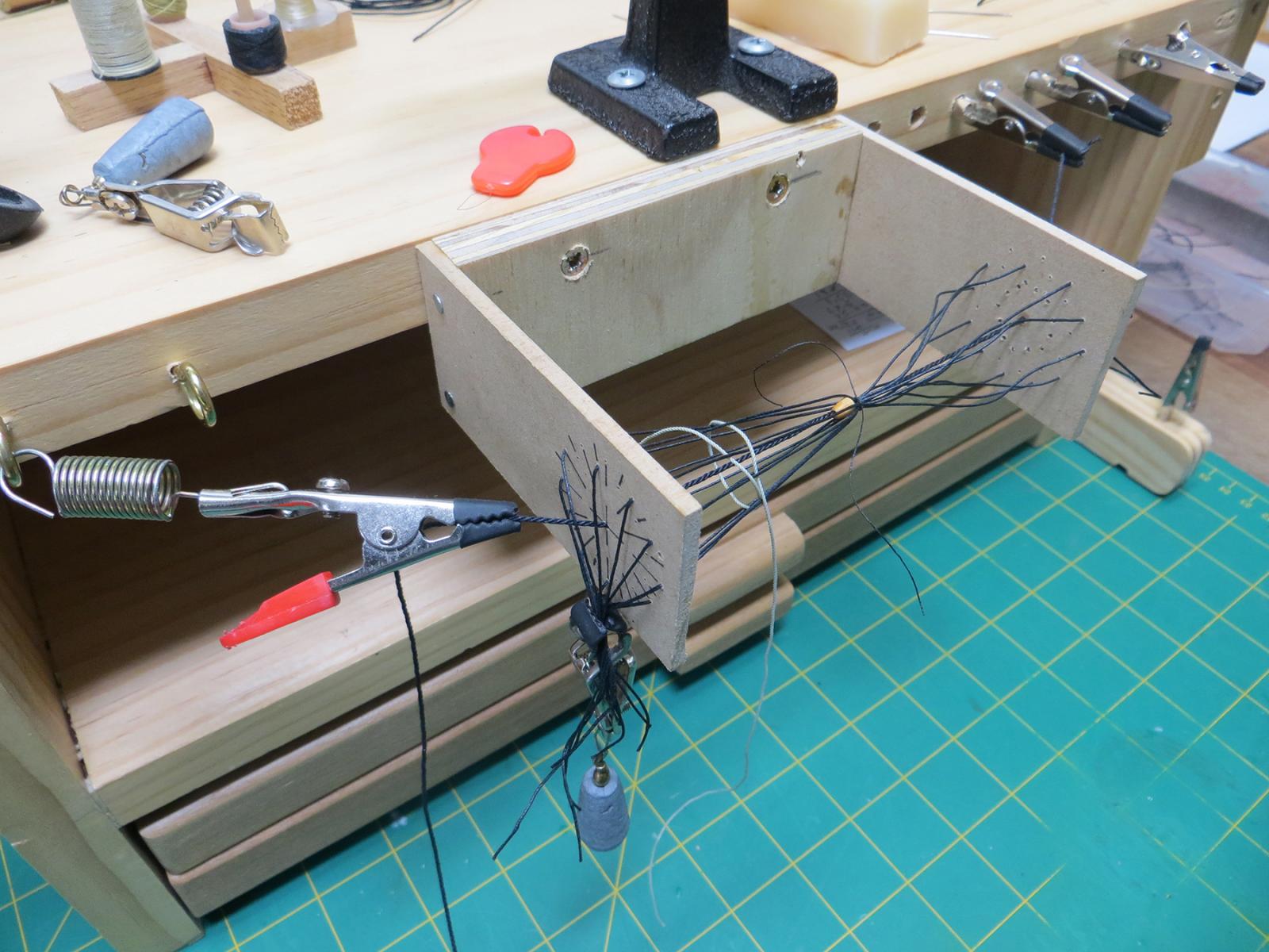
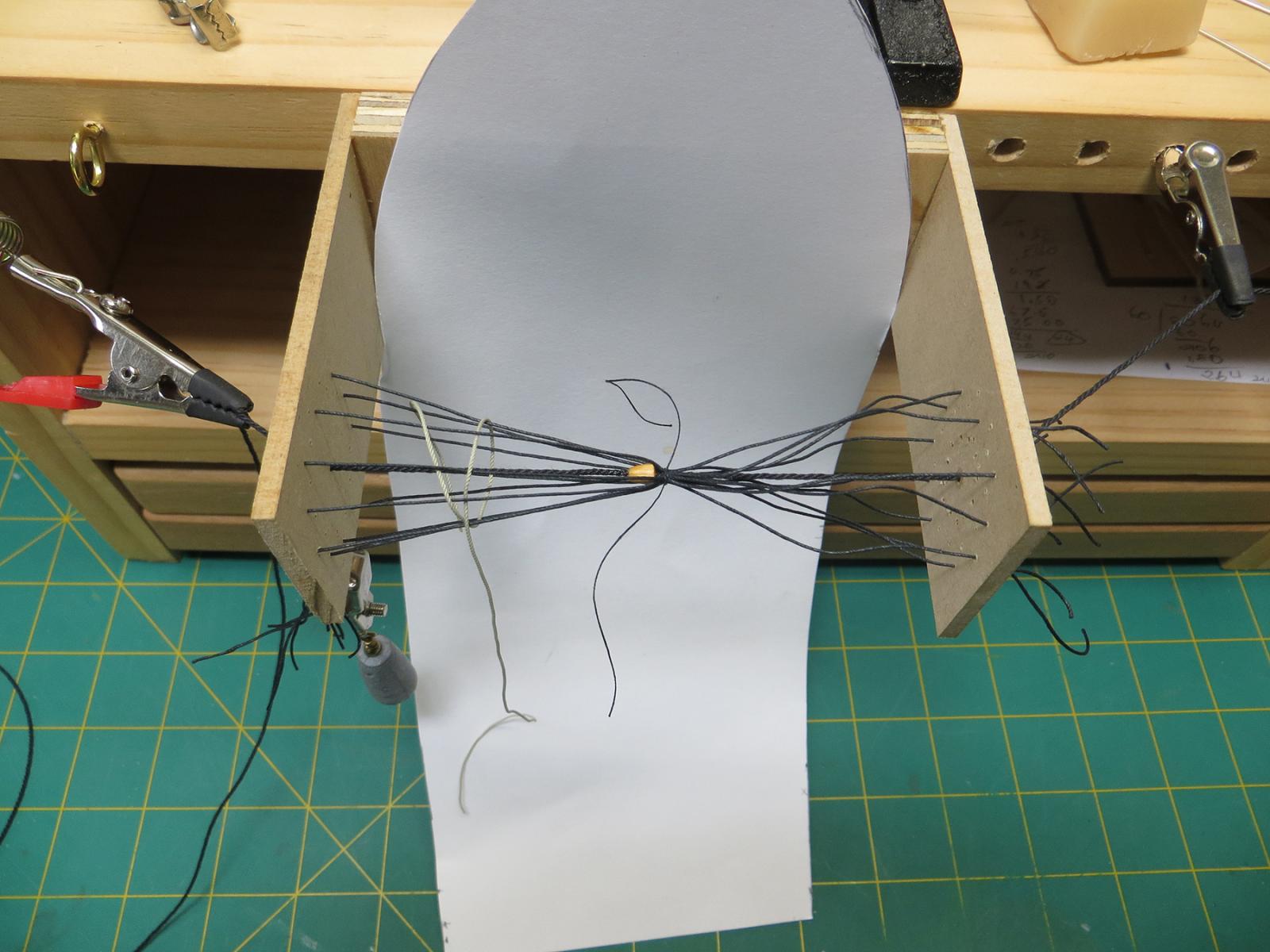
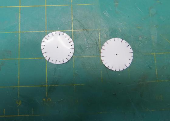
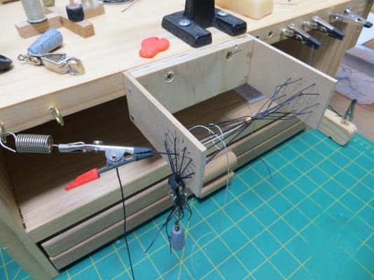
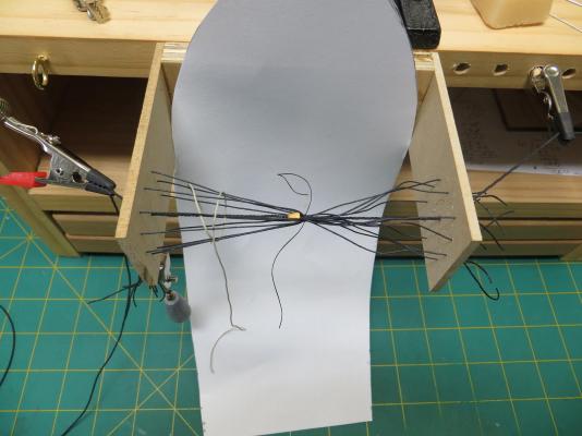
I have been experimenting with jigs for weaving the sock on the mouse for the stays and preventers and have almost got to a final solution. The first of the photos below shows an early attempt using plastic discs with slots cut (alternate slots to a deeper depth) - proved too flimsy and difficult to control. The second jig is working out OK but I made the mistake of setting up an even number of strands to weave around. The temporary fix is to skip one of the strands at the top, but this tends to leave a slightly more open weave along this axis. I have to re make this jig with a spacing that will permit an odd count. I have drilled an inner and an outer set of holes to facilitate weaving under/over but I have found at my scale (1:60) that this is too many strands; but, the additional holes will be useful for 1:48 builds. I hope the photos are self-evident. One of the photos shows a finished Mizzen stay, but I will probably redo this, as close examination shows the uneven weave along one axis (although partially hidden by the loop). These jig ideas are not original and I have borrowed ideas from several members build logs - thanks to all. Please note that the larger thread/strands shown are only to enhance the photo, and the alternate colour is to enhance the weave pattern in the photo - I am using a much smaller thread for the actual mouse at this scale of 1:60.
- 517 replies
-
- 9
-
-
- Endeavour
- Artesania Latina
- (and 1 more)
-
Cat Head dimensions
BANYAN replied to BANYAN's topic in Building, Framing, Planking and plating a ships hull and deck
Hi John, I believe that to be one of the whiskers? And just to show we are making some progress The shiny coat is purely protective (shellac) which will be rubbed back as required to apply the copper plates and then paint the hull black. I am about to make a start on the deck planking.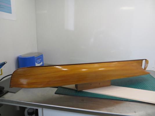
-
Hi, a lot of modellers also use nail clippers for this job as the curved and bevelled cutting edges allow a close 'nip'. If you prefer scissors, then a trip to a nearby sewing supplier might be helpful as they could demo a few pair to you to ensure you get what you need? I also use a pair of shears (about 2.5 to 3 inches long I got from a sewing machine shop (also should be available from any sewing supplier) which are essentially a mini-version of shears. these fit the hand well, have a very sharp edge and a very point tip which allows me to get in close. cheers Pat
-
ancre LE BONHOMME RICHARD by Jeronimo - FINISHED
BANYAN replied to Jeronimo's topic in - Build logs for subjects built 1751 - 1800
Beautiful work Karl, a great display of a master craftsman's work. cheers Pat- 662 replies
-
- 2
-
-
- bonhomme richard
- frigate
- (and 1 more)
-
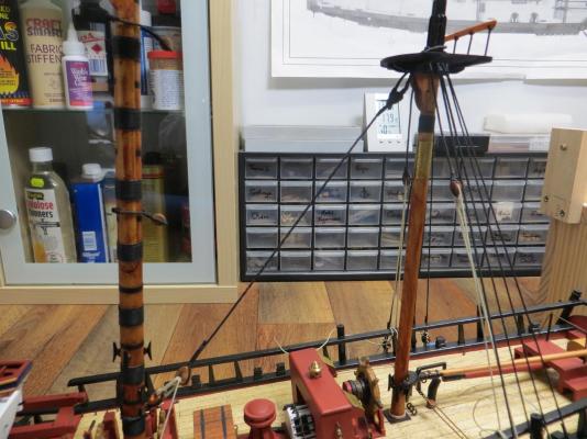
Hi Ollie, looks great mate! WRT the masts; all my furniture at home is Tassie oak with a clear finish. Over about 5 years this has yellowed to a honey colour but does show the grain. I am not sure what degree of grain you will show and whether this would be similar to the masts of the real vessel in appearance. If you are happy with the wood there might be another finish you could consider. I use Huon pine for my masts and have fond a stain made here in Australian (an outback recipe I t believe) called Bushman's stain. When applied to the Huon pine and finished with a dull cote finish (Testors) I think the colour is very similar to that of the masts of the Endeavour replica. I hope this is useful info for you? cheers Pat
- 803 replies
-
- 2
-
-
- colonial cutter
- modellers shipyard
- (and 1 more)