BANYAN
-
Posts
5,534 -
Joined
-
Last visited
Content Type
Profiles
Forums
Gallery
Events
Everything posted by BANYAN
-

HMCSS Victoria 1855 by BANYAN - 1:72
BANYAN replied to BANYAN's topic in - Build logs for subjects built 1851 - 1900
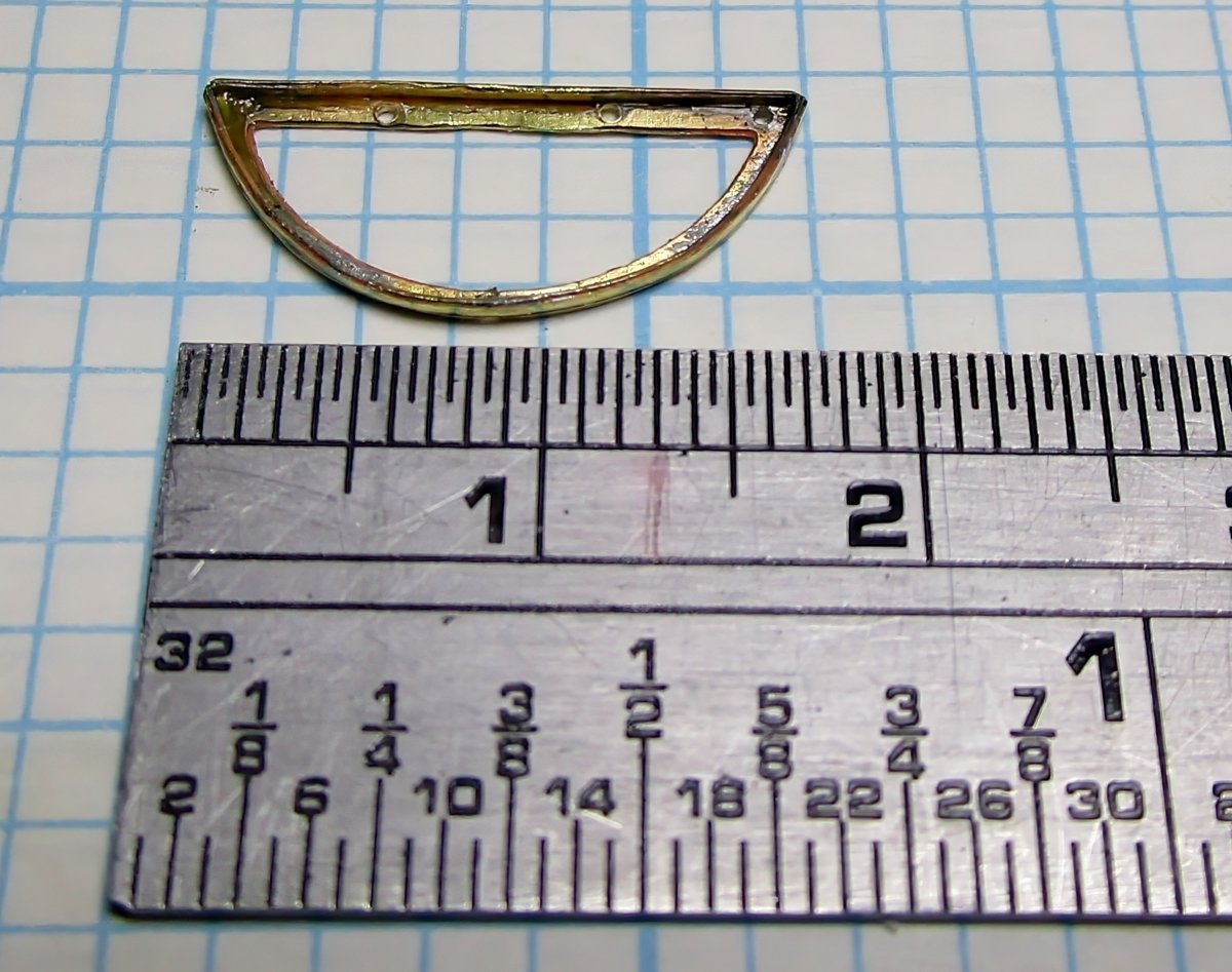
Thanks for the kind comments Keith. Hi Eberhard, actually the piece is dimpled (etched) but I think the guy who etched it left the item in too long and the holes do not serve as a guide as they are a little too large. The drill bit then wonders to one side or other of the dimple recess - that's why they are not aligned on the test piece. I mentioned it to him asking for a redo, but he said that at this size a part and with the thickness of brass stock, to etch completely through the required parts, he cannot control the dimple size. He said he deliberately made the unmasked hole in the template as small as possible but it still resulted in the larger than needed dimples. I do not do enough of this stuff to warrant learning how to, nor warrant buying the etchant chemicals, which would probably lose their shelf life before I used them again - so I will just have to adjust my technique. I have one of those PE folding devices but the fingers are all too small for the longer edge of the rim to be effective. I wish I had one that could be flipped around (long straight edge one side and a series of small fingers on the other). Thanks for the suggestions, you have pointed me to one other possibility. cheers Pat- 973 replies
-
- 4
-

-
- gun dispatch vessel
- victoria
- (and 2 more)
-
HMCSS Victoria 1855 by BANYAN - 1:72
BANYAN replied to BANYAN's topic in - Build logs for subjects built 1851 - 1900
Thanks Eberhard. Still a bit of improvement required though. As you can see the 0.6mm holes nearly slice the metal strip so I need to find a better way to drill these AND keep them aligned. One saving grace is that once the eyes are soldered in, they will be ground flat so the holes will sort of disappear, especially after blackening or painting (not sure which yet). That is why I haven't filed/ground the hole edges yet - will be done later. The issue I am grappling with is to find a way to work (bend) the metal to avoid all that crushing/marring you can see. The folded part is only 1mm and the metal fairly soft which is why it marks so easily. I have to use the flat long nose needle nose pliers to bed as rubber/nylon jaws will not grip properly or allow a bend under pressure. The other way I have tried is using a jeweler's bending block, but that required partial folding at a time rather than bending the whole edge at a time -results in a wavy bend. I'll keep experimenting to see if there is a better way to get a non-marring fold. I am hoping to find a way to use the jeweler's bending block but then use a form of some sort to bend the edge as a single effort. cheers Pat- 973 replies
-
- 3
-
-
- gun dispatch vessel
- victoria
- (and 2 more)
-
HMCSS Victoria 1855 by BANYAN - 1:72
BANYAN replied to BANYAN's topic in - Build logs for subjects built 1851 - 1900
Thanks Keith, with the 'shakes' getting slowly worse I am not sure I can keep doing this real small stuff. cheers Pat- 973 replies
-
- 3
-
-

-
- gun dispatch vessel
- victoria
- (and 2 more)
-
Great to see an update Matrim; frames are always time consuming. cheers Pat
-
The other way to overcome the 'leakage' issue (if it is a concern to you) is to use overpressure. That is a mask with a powered inflow that creates an overpressure which keeps any of the nasties getting in if the seal is not tight. I have a battery powered one (the battery container clips to your belt (or the like) and causes very little drain on the batteries. I got this pretty cheap (same price as paying for a good quality unpowered mask) a few years ago. cheers Pat
-
HMCSS Victoria 1855 by BANYAN - 1:72
BANYAN replied to BANYAN's topic in - Build logs for subjects built 1851 - 1900
Thanks Mark, not too bad for a test run, but hopefully I can do better yet. Keith, I drew up the parts in CAD to scale (including a test legend) and a railroad modeller who lives in the eastern parts of Melbourne etched them for me. I can pass on his details if you need them? cheers Pat- 973 replies
-
- 4
-
-
- gun dispatch vessel
- victoria
- (and 2 more)
-
HMCSS Victoria 1855 by BANYAN - 1:72
BANYAN replied to BANYAN's topic in - Build logs for subjects built 1851 - 1900
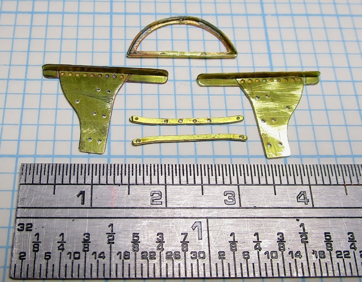
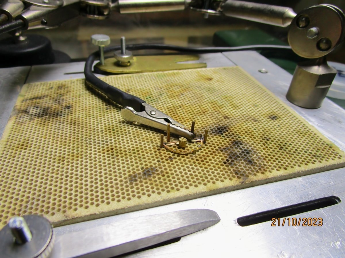
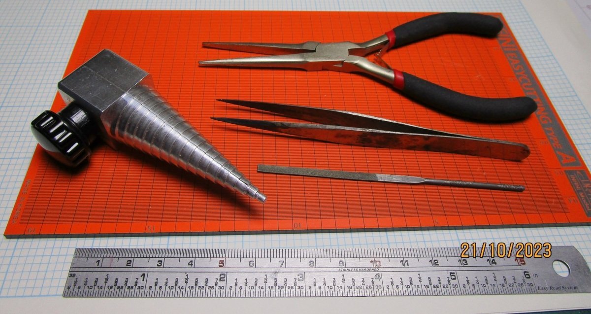
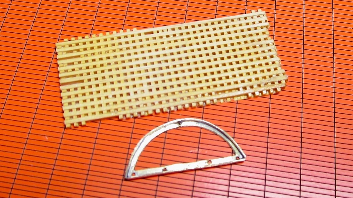
Hi again folks. Some small progress made; well, more experimentation and trials/tests than progress. The Victoria was fitted with skeletal iron tops which when reduced to 1:72 make for some very small and thin parts. My real concern (for the future) apart from blowing them apart when soldering, is that the arms of the cross-trees will bend. I have yet to attach the iron (brass) rod futtock staves which will give them some support (I hope). I drew up the parts and had them photoetched from 0.2mm brass as you can see from the photo. These tests are to see if I can actually solder them. The parts were first folded along fold lines/creases I had etched which sort of worked OK - you have to look closely to see the slights waves/rolls in the parts. I drilled the holes (0.6mm) where needed for the eyes which I will solder into place later. I then had to solder on the curved rim which I formed on the 'wrangler' which you can see in the tools photo - this part is only 1mm high by 0.2mm thick. I put it on my soldering station and held in place with some brass pins and an eccentric cam (thanks Eberhard for the idea and guidance) and soldered with y resistance soldering unit on its lowest setting - and it worked In one photo the part looks very distorted due to the aspect the photo is taken, but in others you can see it is reasonably formed. Next will come the true test, see if the heat sink/paste will work as I solder in the eyes. I'll show the results (hit or miss) in a future post. A club member (Al - AlPays avatar) made the grating for me. They are formed from about 0.6mm combs and staves - how he managed to make it still amazes me. I have yet to form the shape which has me a little bedeviled at the moment as I think shaping by any form of power tool will simply blow these apart. The next task, to solder in the eyes and the other parts together, is to make a wood jig that will hold the elements the right distances apart. cheers Pat PE Parts Parts pre-formed Soldering the rim in place The soldered part (before cleaning up) Tools used The grating (the rim/part looks distorted but is not in reality)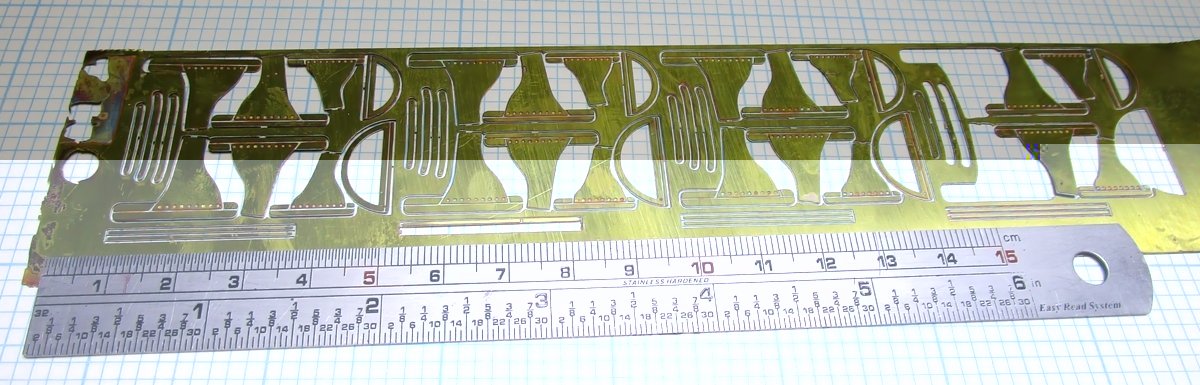
- 973 replies
-
- 12
-
-

-
- gun dispatch vessel
- victoria
- (and 2 more)
-
A great idea, and execution, for the lettering, I'll stow that in my kitbag of ideas. cheers Pat
-
Well for someone ho doesn't like planking you're doing a pretty decent job of it Steven cheers Pat
-
A very nice little model Allan, as you say 1:96 can present some challenges. cheers Pat
-
Your build of Speedwell is looking very good Chuck, I continue to be amazed (and jealous) with your skills in doing such clean joinery. I hope you don't me commenting with an unsolicited suggestion. I have had success with, and like, your 'paper' friezes that you have provided me in the past and they looked good when applied. If you are experimenting, have you thought about trying to find someone that prints 'embossed' card/paper? If the costs are acceptable, that may be an option for you that offers some 'relief' to the printed friezes. I have never had the need to have this done, but I have thought about using a business card printing service who offers embossed/raised lettering services. I considered this technique for the basic 'gingerbread' on the bows of the Victoria. However, as the detail was minimal, we ended up using cotton threads pasted to the headboards. Offered for your thoughts/comments only as it may also prove unpractical, and you may already have completed your experimenting. cheers Pat
-
That came out a treat Allan, nice work. cheers Pat
-
Hi Allan, I hadn't noticed this build of yours; very nice work. on that plug. I'll be interested to see how you progress with this one. cheers Pat
-
Hi Mike, sorry I missed your build here. That section model looks great- very nicely done., cheers Pat
- 47 replies
-
- 1
-
-
- Fubbs
- Weasel Works
- (and 1 more)
-
Great to see you back at this build Keith; sorry I missed your return. The build is coming on very nicely. cheers Pat
-
HMCSS Victoria 1855 by BANYAN - 1:72
BANYAN replied to BANYAN's topic in - Build logs for subjects built 1851 - 1900
Okay, okay I get the hint - I'll see what I can do. Eberhard, I may end up having to do the really small spars such as studding sail booms, and maybe even the gaffs from metal as you have suggested, but painting them to match the wood will be a real challenge. cheers Pat- 973 replies
-
- 4
-
-
- gun dispatch vessel
- victoria
- (and 2 more)
-
HMCSS Victoria 1855 by BANYAN - 1:72
BANYAN replied to BANYAN's topic in - Build logs for subjects built 1851 - 1900
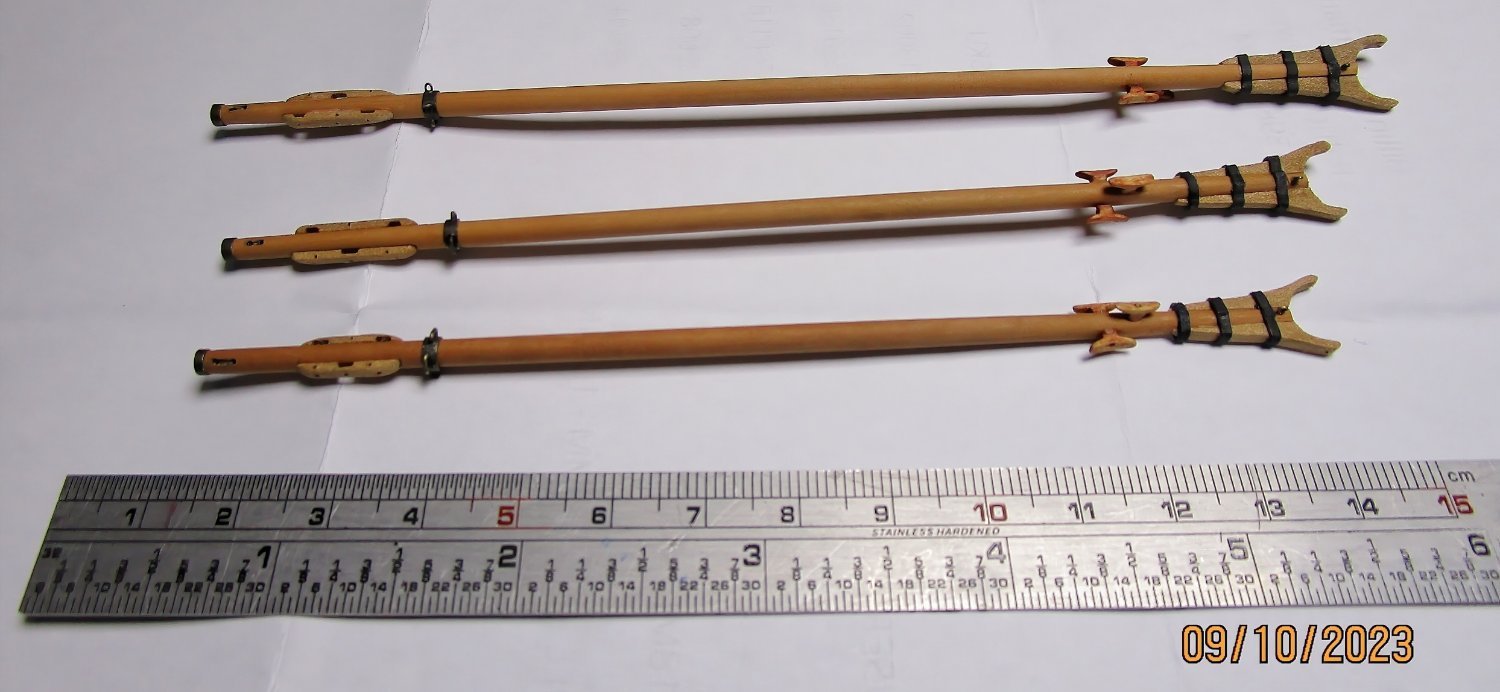
Hi again all. I have been slowly working on the booms since my last update as you can see in the attached photo. I have still to add the parrel ropes and a couple of blocks for the guys, as well as leather the inside of the jaws. The spiderbands and end band are made from thin wall brass with the eyes and ears soldered in, then blackened (as shown in an earlier post). The Jaw bands are black paper card as I need them to conform with the ovoid shape of the jaws and indentations - the thin brass I intended using just would not hold shape properly and gluing them was getting messy. About 3 remakes later.... see the result (acceptable I think). it took a few tries to find a wood that matched the wood I used for the spar proper. The spar is Kaurie, and the furniture Ballarat Pear - the Kaurie kept splitting when trying to use it for the finer detail. I am also still not that happy with the cleats but they are so fiddly to make, and I do not want to use small plastic ones as they will be difficult to paint (to match). I have not put pulleys in the slots of the reefing combs yet; still thinking on how I will do that (to keep them looking realistic). for some reason (camera perspective I think) the jaws look shorter and wider than they actually are. I am now trying to figure out how to make the mast partner wedges/collar. This will be done on the lathe and textured to look like canvas (the individual wedges do not need to be scribed as they will be covered). The problem I am now trying to solve is how to keep the collar horizontal (to fit closely to the deck), with the mast holes at rakes of 5, 10 and 15 degrees for the fore, main and mizen masts respectively. My current plan, which I hope will work, is use some oversize stock (in diameter), drill out the core to the mast diameter, then turn the outer dimension to size. My plan is then to put this in a jig of some sort (still being thought on) to allow me to cut/slice it off at the mast rake angle. Hopefully this will result in a collar that is close fitting at the deck, accepts the mast at the correct angle and will retain a uniform size all around the mast. cheers Pat
- 973 replies
-
- 13
-
-
- gun dispatch vessel
- victoria
- (and 2 more)
-
Welcome back Eberhard, have been missing your updates (as if I have been posting ) Those extra details really add to this wonderful model. cheers Pat
-
Hi Allan, to me 'A' looks a bit like the pedestal for a swivel gun (fitted much like they were in HMB Endeavour). The shape looks octagonal, which is right, and the bulk is fitted behind the bulwark which explains the red. But my concerns for this suggestion are that it appears a little deep (long) but then again could be the support/strength they needed; and, I cannot fully reconcile the item at its head, which is similar to that of 'B', - but perhaps these are intended to represent iron rings/hoops driven on to strengthen the top ends? Just a though and bracing for incoming fire cheers pat
-
Keep at it Gunga Din, you'll get there. I have the same issue with the booms, so many small parts to add but I am almost there cheers Pat
-
Nice find, and thanks for the info; another tid-bit to file away. cheers Pat
-
Thanks for your response Ian; your response highlights that I may not have been as clear as I should in my wording. I think your answer was definitive, but just in case, what I tried to say, was that while two oars are fitted, only one was typically used at time? From your response though I gather that both oars were either united or manned? Just interested cheers Pat
- 502 replies
-
- 2
-
-
- Quadrireme
- radio
- (and 1 more)
-
Coming along well despite the set-backs Ian. An interesting video. One small point, while I am unfamiliar with this period of history, many oar steered vessels only used a single oar at a time. Were these vessels using two? Perhaps a trial with a single oar may offer different effect? cheers Pat
- 502 replies
-
- 3
-
-
- Quadrireme
- radio
- (and 1 more)
-
Well Glen, there is always the 'dancing (Bundy) bears' cheers Pat
- 290 replies
-
- 5
-

-
- Quinquereme
- Finished
- (and 1 more)
-
This is an extraordinary bit of modelling Glen; very nicely executed and presented - and added entertainment in the build log to boot . The sea surface turned out really well, you have a gift for making water look realistic. cheers Pat
- 290 replies
-
- 4
-
-

-
- Quinquereme
- Finished
- (and 1 more)