HOLIDAY DONATION DRIVE - SUPPORT MSW - DO YOUR PART TO KEEP THIS GREAT FORUM GOING! (Only 72 donations so far out of 49,000 members - Can we at least get 100? C'mon guys!)
×


BANYAN
-
Posts
5,946 -
Joined
-
Last visited
Content Type
Profiles
Forums
Gallery
Events
Everything posted by BANYAN
-
 Nice result Eberhard. I am enjoying following your foray into the unknown with these materials. cheers Pat
 -
Agree with Trevor. The contract for Victoria called for mats as well as baggywrinkles. The best I have been able to determine so far,. is that the mats were usually laid across yards whereas the baggywrinkles were applied to lines (both at any point of contact or potential contact with sails). cheers Pat
- 15 replies
-
- 1
-

-
- baggy winkle
- service
- (and 2 more)
-
That looks so good Ilhan. I now have to go back and possibly adjust the funnel on my Victoria as I didn't even think on hand rungs to climb the funnel. Great seeing more of your quality work. cheers Pat
-
That a great achievement Bob, and you didn't even go cross-eyed. cheers Pat
-
Be over in a jiffy mate - just have to save my pennies for a while. Seriously though, your rigging is looking great, clean and proportionate in scale - well worth celebrating. cheers Pat
- 301 replies
-
- 5
-

-
-
- Constitution
- Bluejacket Shipcrafters
- (and 1 more)
-
Hi Richard, I actually do all my spars on my Sherline (long bed) lathe. I first cut the required square and hex shapes slightly oversize, the (very roughly) shape them to a hex taper using a plane and then set it up in the lathe and use small machinist jacks and a follower rest to shape the final profiles. I use a combo of rasps, files and sandpaper for that process constantly checking the profile with calipers etc. For shorter sections I sometimes use the duplicator, especially about the hounds and masthead doubling. I then refine the squared and flat surface manually using a file rest and fine needle files to get them to the final dimensions. You can see some of my earlier dings (collision scars) between the Y cross-slide and the chucks before I made a stop for it Well, one has to learn some lessons the hard way; I put it down to the experience of learning. PS: Sorry, I should mention that I mainly work at 1:72 so, at your scale you might have some difficulty setting up spars etc. cheers Pat
-
A great diorama Greg, looks good and nicely detailed. I wonder though how they drink those beers on the Quarterdeck table with all that protective gear on I have enjoyed following this build. cheers Pat
-
Sorry to hear the news of the delayed recovery mate; best wishes for a better progress. cheers Pat
- 714 replies
-
- 1
-
-
- lady nelson
- victory models
- (and 1 more)
-
Good to hear you are on the recovery path Mark, I hope all continues to go well for you. Look forward to seeing the up[dates... and, I know whay you mean by the scales for older ewyes. 1:72 is straqting to do my head in also cheers Pat
- 11 replies
-
- 3
-
-
- half hull
- half hull planking project
- (and 1 more)
-
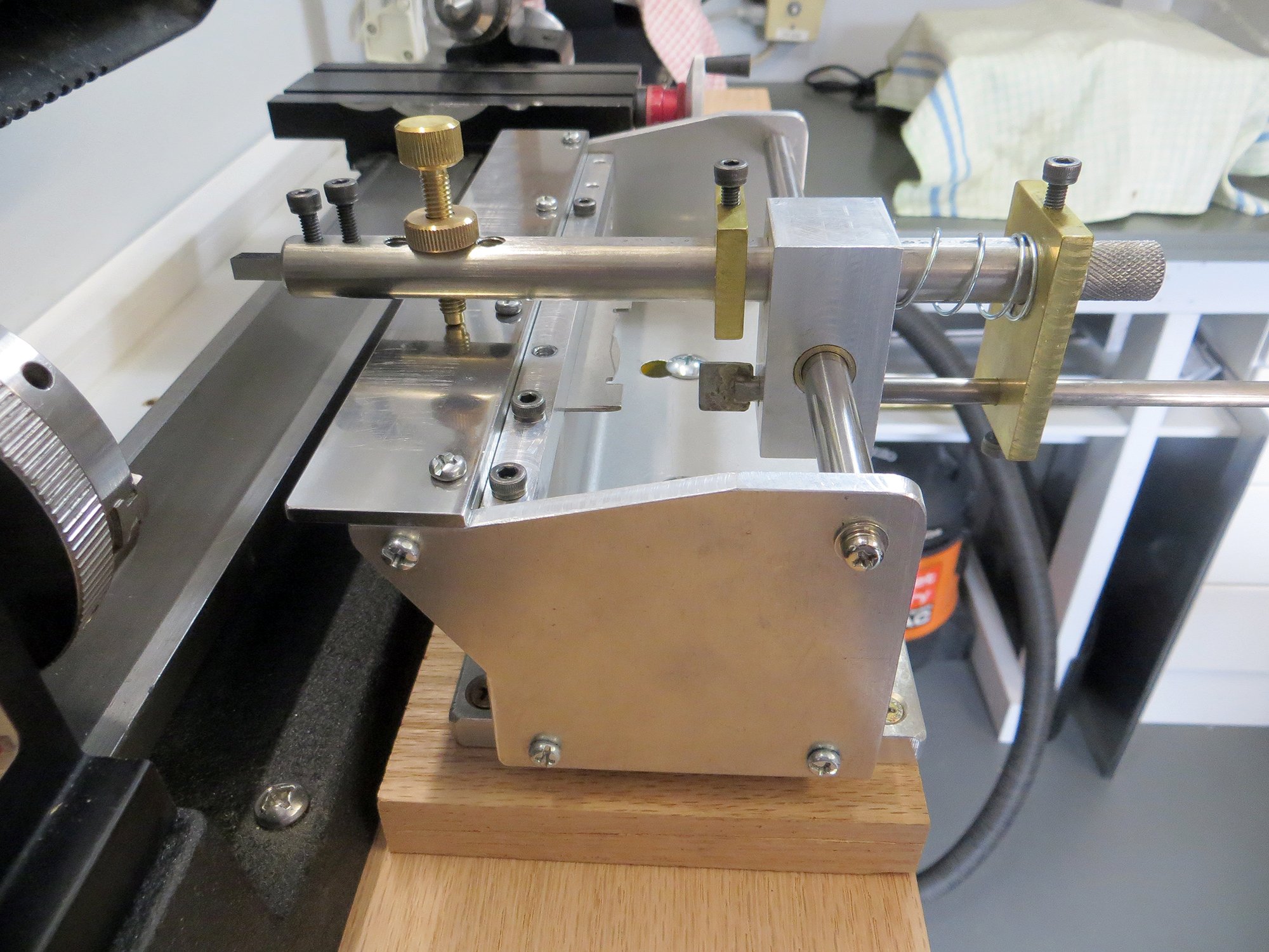
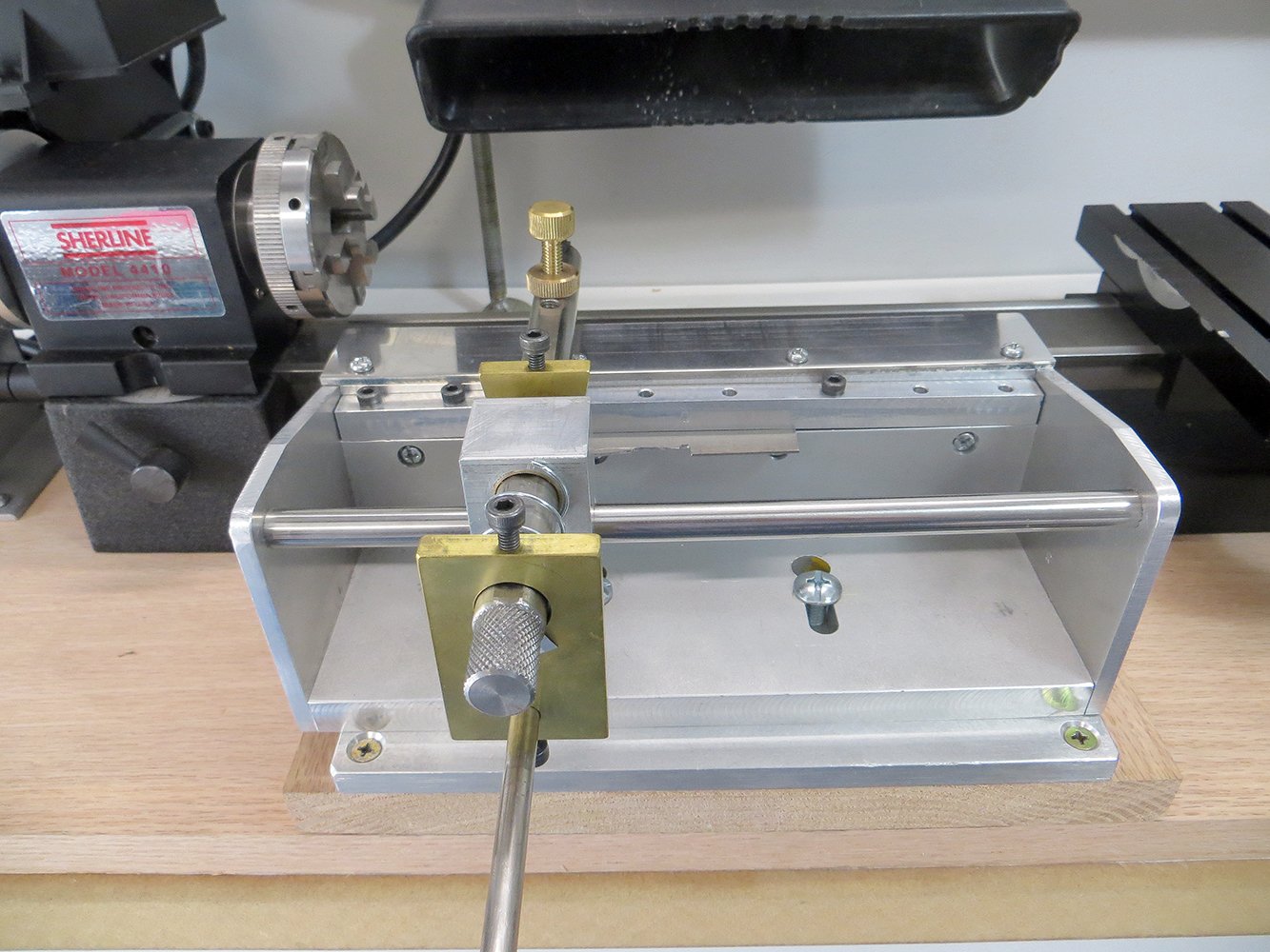
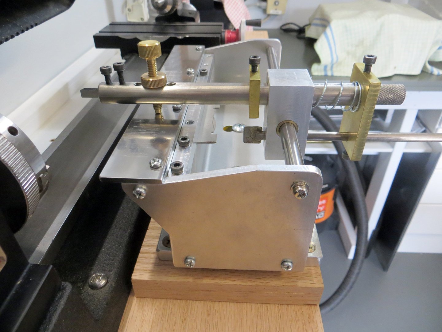
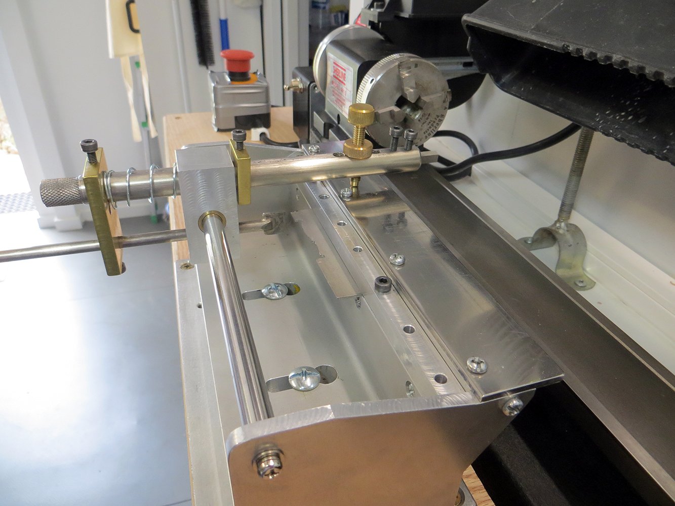
Hi Richard. This is one (home-made) that I use with my Sherline. The idea is to cut a profile (template) in metal that is used as the master profile for as many duplicates as you need - works best with more complicated shapes but will work with a simple flat/tapered profile also. However, I usually use a compound slide to cut tapers on the Sherline, but that only works well over shorter distances. Hopefully the photos are self explanatory, but essentially, the cutter (top) will only cut as deep as the profile follower (bottom bar) and the template will allow. cheers Pat
-
Well here's raising a cup of very strong tea (only slightly laced with ...) to your success with the gingerbread Keith; that is some very nice work. We are becoming accustomed to your very fine work but you continue to impress us. cheers Pat
-
You are being too kind to the crew Keith - a good flogging to drive them up steeper ladders/stairs should be the order of the day Seriously though, Lula is coming along nicely, great work. cheers Pat
- 732 replies
-
- 8
-
-

-
-
- Lula
- sternwheeler
- (and 1 more)
-
Interesting but very effective approach to cutting the tapers Richard. Appears this approach may be easier than setting up a shape follower (duplicator) arrangement. cheers Pat
-
Hi Bob, sorry I am late to this log; somehow missed it. Great job you are doing here in completing the model - she is looking very 'shmick' - Jim seems to approve. cheers Pat
-
OK, I'll continue the thread - fourth! Seriously, nice work Glen, looks really good, especially the proportions. cheers Pat
- 301 replies
-
- 4
-
-
-
- Constitution
- Bluejacket Shipcrafters
- (and 1 more)
-
John I would ignore the lot of them! You are the one doing the work and you govern the pace; not like you are under a Contract. So if you want to take your time you should; but, as you have indicated your intention to complete ASAP, that is your call and they should respect that. It is really a bit cheeky of them pushing you if you are doing this on a voluntary basis; they should be grateful and encouraging. She is looking great BTW, very nice work. cheers Pat
-
Agree with Eberhard. Great job on the masking Keith, those lines look good. So, has the heart rate stabilised? cheers Pat
-
Just like sox in the wash - never [know] where they disappear to Nice work Eberhard. It is just too easy to forget the scale you are working at here sometimes. cheers Pat
-
Tom, probably by voice pipe and possibly also bells. cheers Pat
- 732 replies
-
- 4
-
-
- Lula
- sternwheeler
- (and 1 more)
-
Welcome back, great to see the build progressing. cheers Pat
- 1,215 replies
-
- 1
-
-
- sloop
- kingfisher
- (and 1 more)
-
It takes a brave man to admit defeat, but you gave it a really good effort mate. Look forward to seeing that addition. cheers Pat
- 732 replies
-
- 5
-
-
-
- Lula
- sternwheeler
- (and 1 more)
-
This is building into an exceptional diorama Greg. The figurine painting skills you show are top-notch. cheers Pat
-
Great milestone Glen, one which I thinks not only deserves that drink BUT also an extra Rum Issue (break out the Bundy). All looks great, nice job! cheers Pat
- 301 replies
-
- 4
-
-
-
- Constitution
- Bluejacket Shipcrafters
- (and 1 more)