


BANYAN
-
Posts
5,540 -
Joined
-
Last visited
Content Type
Profiles
Forums
Gallery
Events
Posts posted by BANYAN
-
-
As Keith has hinted, I think you made an editing error Glen - the penguin text was crossed out
") " Oh no, not the penguins, not the penguins!"
" Oh no, not the penguins, not the penguins!" ")
Seriously though, that wall is coming along really nicely, are you going to do any weather and/or scum line etc?
cheers
Pat
- GrandpaPhil, mtaylor, Keith Black and 3 others
-
 5
5
-
 1
1
-
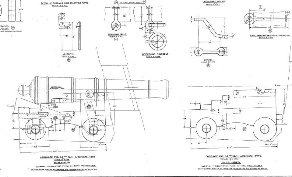
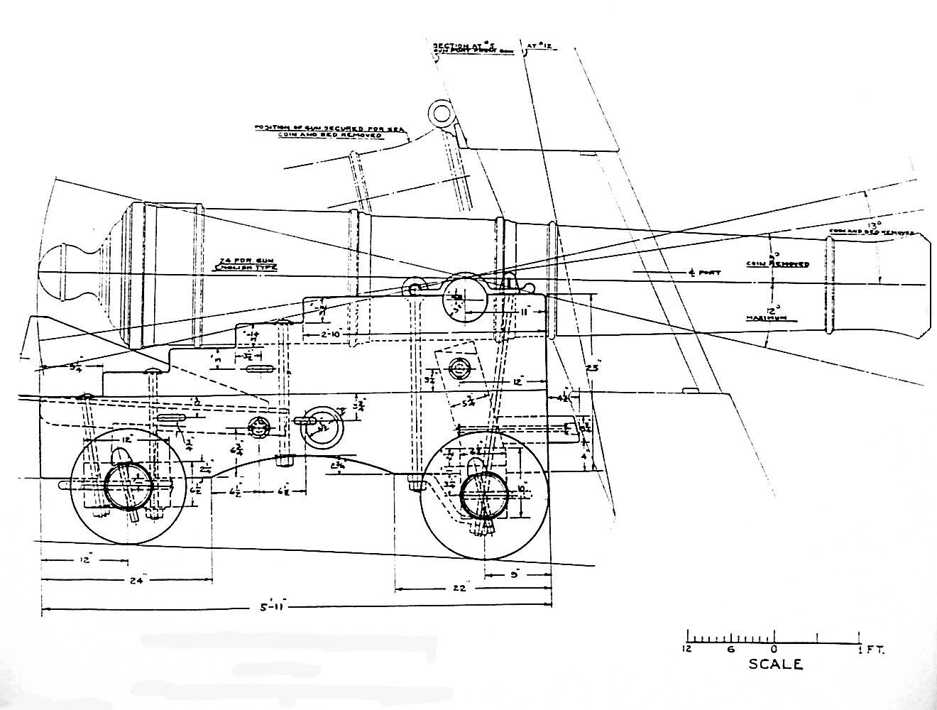
Unfortunately, they are the best resolution I have Allan. I can send the files I have, just in case MSW's file formatting changed the res, but I don't think they do that? Let me know if you still want them?
In the meantime, I will make a crop of similar size as yours and try some of the image software I have to see if I can improve it. (Sorry Allan, I tried that, but the original is of very low resolution, and I cannot improve it enough to read the dimensions). Perhaps contacting them may allow you to get the dimensions or a better resolution copy? Another option may be to import the improved image of the gun (second image) that has a scale, into CAD, scale to get the image to proper dimensions, and then measure them?
cheers
Pat
- mtaylor, thibaultron and Keith Black
-
3
-
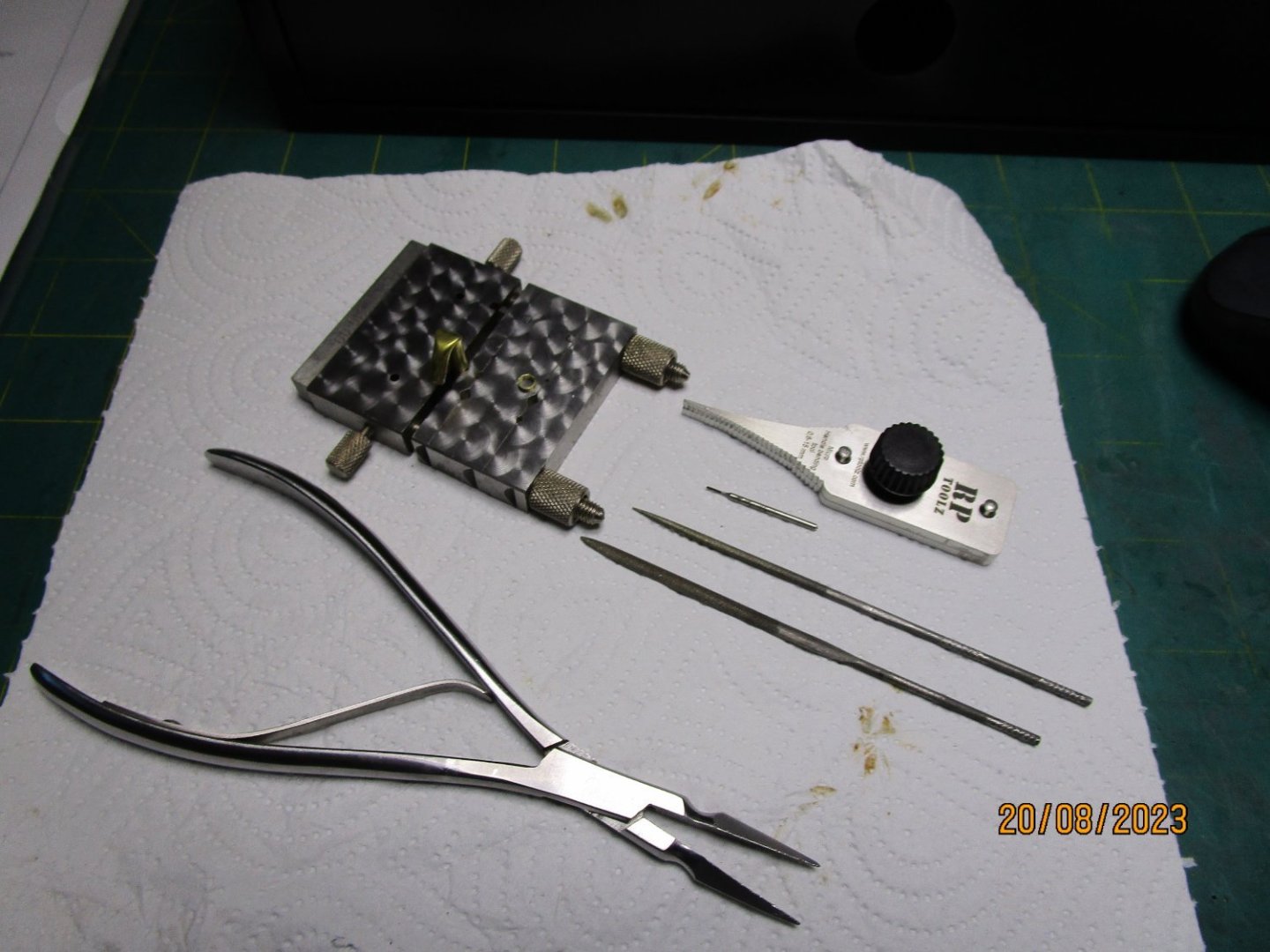
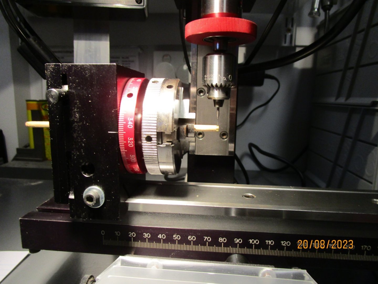
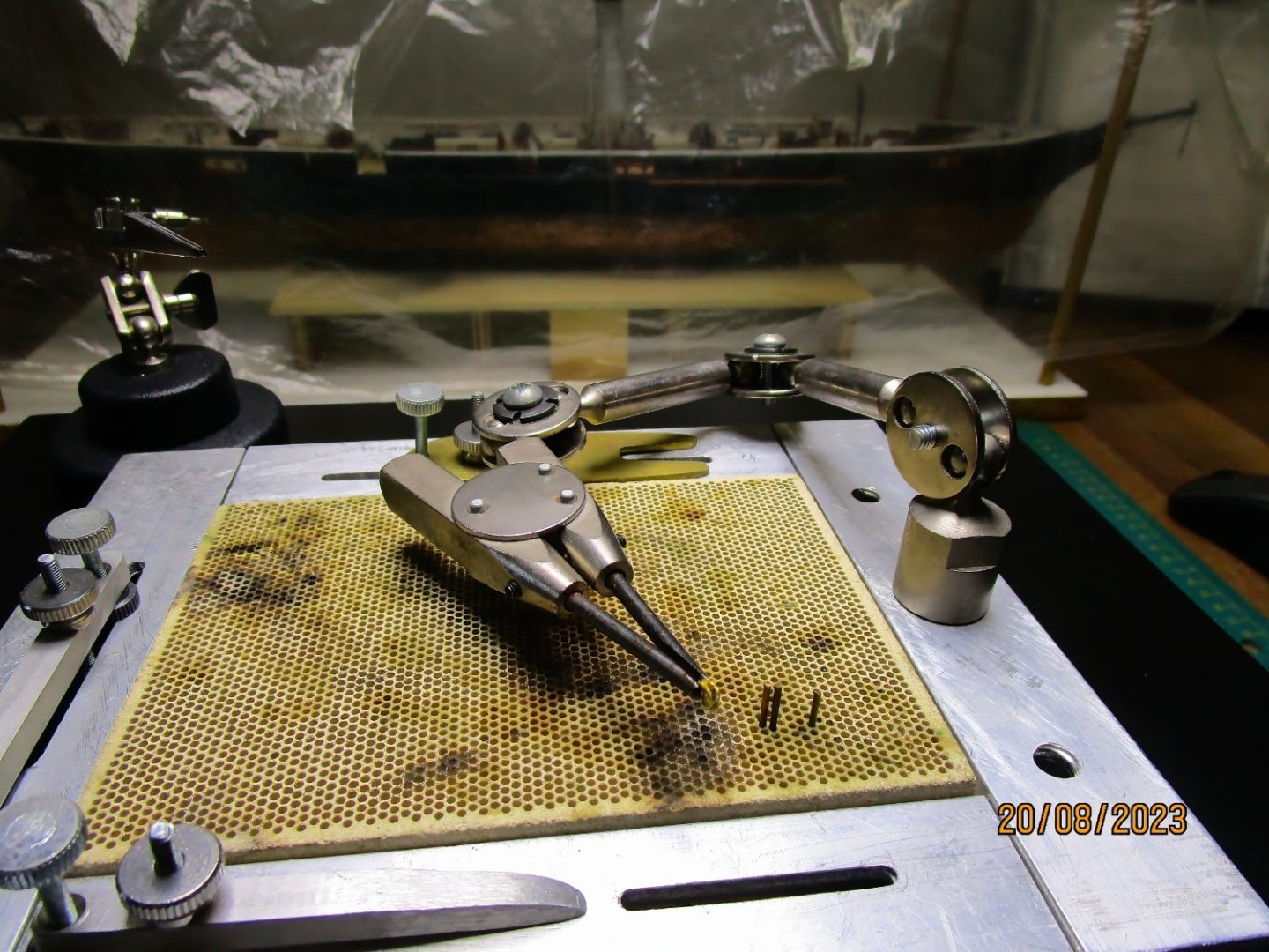
I thought I should add some photos to also help explain how I go about the process.
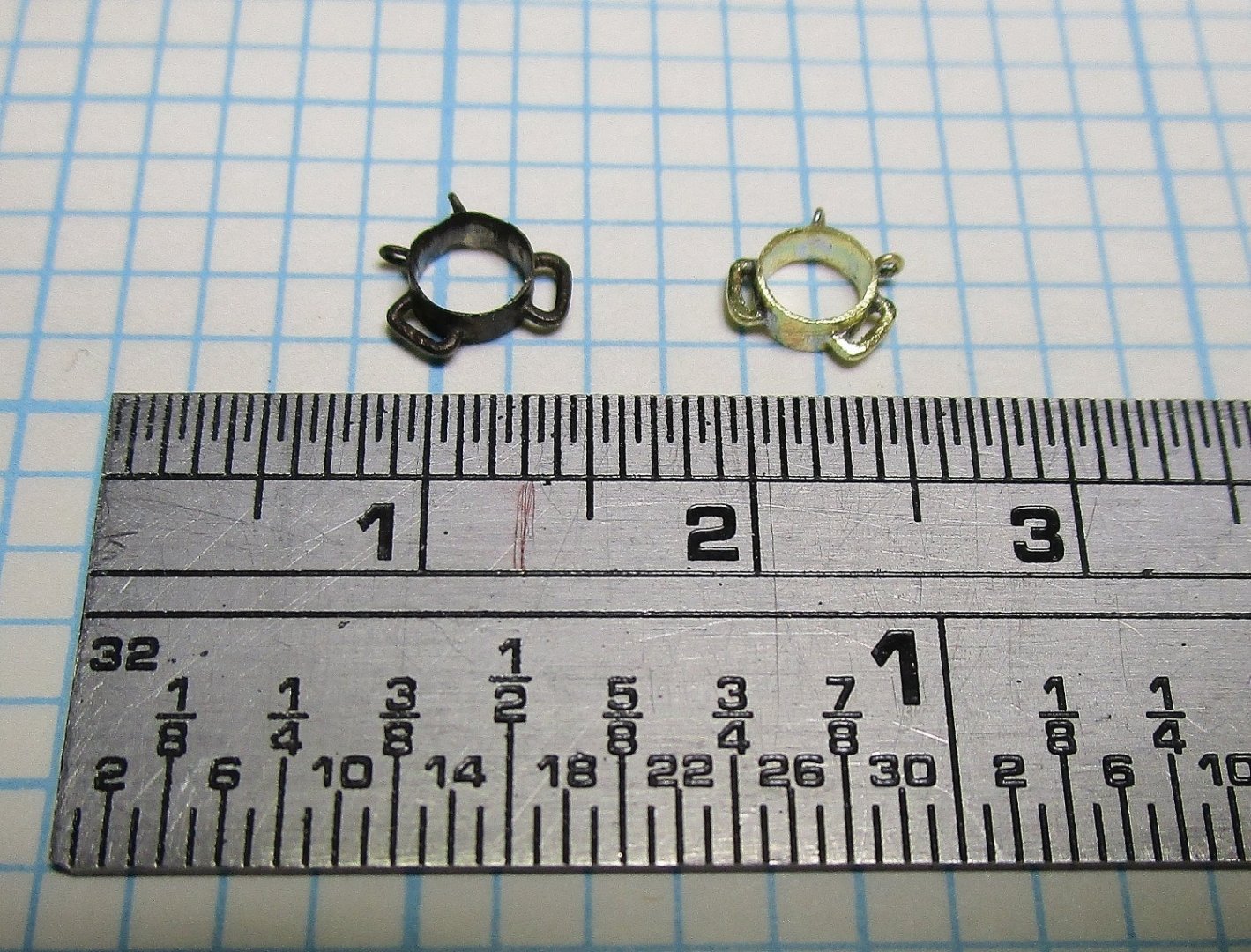
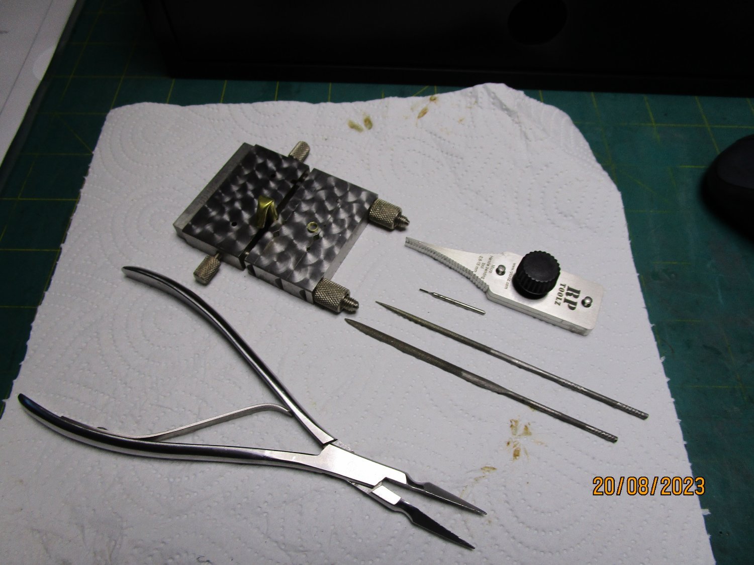
The first shows the tools I use for the metal forming part, which include a pair of pliers with serrated grip jaws, a couple of needle files, a small 0.5mm spade bit used in my mill (next photo), a jewellers type metal block (can't remember the name) but it allows me to hold tubes of various shapes at 90, 45 and 30 degrees and cut off small pieces to width, and the JB Tools grab handle making tool.
The second shows the set-up with the band on the wood mandrel in the rotary indexing attachment for the Sherline mill.
The last shows the band, which has now been drilled to indexed angles at 020, 100, 160, 200, 260 and 330 degrees, being held in my alligator jaws in a soldering station I have cobbled together (still being improved).
cheers
Pat
-
Allan, I will have to search through my reference material again, but if I recall correctly the straps, or more correctly stays, are two metal brackets that were used to secure/support the axle which was morticed into the brackets. The strap (stay) replaced the lower washers for the brackets bolts that also served to secure the cap square on the upper side of the brackets. Note the bottom part was straight not curved and aligned with the squared part of the axle.
(Edit) I found this which sort of explains the 'stay' a little better - I cannot recall at the moment where I found this but may be connected with the "USS Constitution". It is possibly from the Naval Historical Foundation.
cheers
Pat
- Keith Black, thibaultron and mtaylor
-
2
-
 1
1
-
Agree with you about the securing - I did not note that the after pin did not penetrate the deck. However, I thought the bolt you drew looked OK based on the end of a forelocked bolt protruding from the inboard end? The artist may only have shown one as the other might have been obscured being in line? That way, two bolts passed from outboard through the bulwarks and forelocked with pins inboard would secure the head. Gary's model from the NMM does not show these, but the rest of the model fits the idea? I think that is the only way the fighting head could be secured? Other models of gun models I have seen also omit some details so I think another drawing would be useful to prove/disprove these bolts?
cheers
Pat
- allanyed, thibaultron, Keith Black and 1 other
-
4
-
Thanks Rob, appreciate the kind comment. I don't blame you for avoiding the soldering. (see following comment)
Thanks Grant, appreciated. To be clear on the soldering, I use solder that has silver content rather than the full-on silver solder. These come in various melting points which allow me to place items close to each other without disturbing the earlier higher melting point joints where I do that (not in this case). The other big advantage, and relevant to Rob's comment, is that some time ago I invested in a resistance soldering unit (American Beauty) which allows much better control of where and how much heat you place. If it wasn't for this unit, I also think I would not attempt anything this small (especially with the shakes in my hands these days
 ). I am also starting to experiment with heat gel to protect some joints (heat sinks) but at this size a little difficult to place it properly. I find that dialling down the current of the solder unit to minimum, I can solder wire down to 0.2mm or so.
cheers
Pat
-
Allan, looking at that side view is it possible the bottom timber is a fighting head (I think that is the timber at the front of a carriage is called) which is locked in place with the shorter pin. The head would be hard up against the waterway/spirketting and then becomes the timber on which the slide proper would pivot using the longer pin? That way the whole assembly could be removed when required. In this configuration both pins could be on the same axis also? Just a thought.
cheers
Pat
- thibaultron, Keith Black and mtaylor
-
3
-
Good question Rob, and a good pick-up - thanks for keeping me honest
. I should have been a little clearer in my descriptions.
The fore and mainsail booms were about 3.5mm to 3.8mm ID; the Driver boom is only 2.8mm (in my haste I left the decimal out) - BUT it is frustrating and very fiddly trying to get those fitting on. That particular band is testing my patience at the moment
. The eyes and ears are made from 0.3mm brass wire for the Driver band, and 0.5mm wire for the former ones - BTW the ear's ID is only 1.5mm long with less than 1mm gap. My description was intended more for the Driver boom spiderband, as I need to make that one the same way for them all to look alike. I was simply trying to point out the risks in 'fixing/making' the bands using the drilling method. I learned this through some major frustration in having to remake the jibboom a few times as I tried that at 3.25mm and it kept breaking - hence my reluctance. Sorry for any confusion folks.
The way I make them is:- I find the nearest size (ID) thin-wall brass tube under the circumference of the boom at the fitting point then stretch it to size to thin the wall further. I thin fit it to a wood dowel mandrel to hold it while I put it in my mill holding the mandrel in the chuck of my horizontal indexing tool. I then drill the holes using a 0.5mm micro spade type drill bit (which I found in England) at the appropriate spacing. I bend the ears using a JB Tools tool (used for making grab handles etc in trains and tanks etc) at the appropriate size to form 'U' shaped ears that I then manipulate (to get the appropriate leg angles) and with a LOT of frustration eventually get them to sit in their holes (that's why there are pliers grip marks on them). The eyes are twisted using very thin diameter brass wire and placed in their holes. I then apply the flux and solder chips and solder all in one go. The inner dag ends are then cut away and/or filed to smooth and clean the inside of the band. Hopefully this clarifies the situation a little?
cheers
Pat
-
Thanks for looking in Glen and Keith, I very much appreciate your supportive comments.
It's actually good to be getting back into it Keith. One benefit of the slow down though is that I have been able to refine some of the research. Whereas I initially believed the spiderbands to be located at the Given Diameter (GD), or hance, of the boom, it eventually proved to be located much further out. If I had rushed in and glued them in situ at the GD, I would have had to remake the booms (for a third time
)
cheers
Pat
- mtaylor, Keith Black and Glen McGuire
-
3
-
11 hours ago, rwiederrich said:
I probably would have drilled all the holes tightly fit in all the eyebolts and large slide rings into their holes...then simply soldered everything and then ground out the excess from within the band....all in two steps. Or, (My typical method), I would have taken the sloppy, lazy road and drilled the holes and after the band was placed on the spar, then redrill into the wood spar and insert the eyebolts and slide rings in place and glued them in
Thanks for looking in and suggestions Rob, much appreciated. I did the former.
After placing the eyes and the 'ears', I soldered everything in one go, then cleaned out the excess by grinding and filing. I had to be careful there as in my test piece I was little excessive and filed some corrugations into the band by thinning the edges too much. I couldn't use the second method you suggested as the boom is less than 2mm at this point and drilling four holes will probably have broken the boom at that point.
cheers
Pat
- Keith Black, Glen McGuire and mtaylor
-
3
-
Welcome back Vlad! That is a fair bit of progress on the rigging which looks very neat and nicely done.
cheers
Pat
-
10 hours ago, Glen McGuire said:
The only thing left is to add some texture to the water along with a few whitecaps. Then it's time to put on my Archimedes hat and start building the claw!
Glen, don't forget you still have the penguins to do also
Seriously though, that is quite the achievement, she looks great in her glass home, and is a tribute to your patience.
cheers
Pat
-
Thanks Tony, very fiddly little things indeed.
cheers
Pat
- mtaylor, druxey, Keith Black and 2 others
-
5
-
Okay, I finally committed to attempting some of these fittings. Attached is a trial piece (blackened) which was sized for the mainsail boom, and the actual spider band for the topping lifts and sheet blocks of the foresail boom. With the test/trial band you might notice the ear loops are different sizes where I experimented with what looked best/more correct - I also got a little too aggressive with the filing (removal of the solder etc). I still have some clean-up to do on the loops of the actual piece to try ad polish out some of the 'jaw marks' as I had to forcefully manipulate the ends into their receiver holes before soldering them.
The booms have been made and the jaws fitted to them, but I am still determining the best material to use, and the easiest way to form the reefing combs before finalising the booms. Still ahead are the boom hoops for the jaws, and the hoop at the very end of the boom.
Slow progress but getting there.
cheers
Pat
- Louie da fly, mtaylor, Keith Black and 9 others
-
8
-
 4
4
-
Looking really good Steven, those mock-ups are a good way to bowl-out any issues before fitting the actual.
cheers
Pat
- mtaylor, Louie da fly, Glen McGuire and 2 others
-
4
-
1
-
Wow Glen what an effort, and the result is well worth the prolonged 'fight' you endured - it looks great in its new home. I admire your persistence and 'never give up' attitude. 👋
I also liked your boxing match analogy, very appropriate in this instance. Now Rocky Balboa, slap some ice on those bruises and have a good rest
cheers
Pat
- Canute, Knocklouder, Glen McGuire and 2 others
-
3
-
2
-
-
Great to see you complete her, she looks great - congratulations! You should be proud of your efforts as you have come a long way in your build techniques etc.
cheer
Pat
- Knocklouder, mtaylor and Keith Black
-
2
-
1
-
I couldn't agree more Eberhardt and Steven. My plan was to simply put in some notches (about 0.75mm long) and the holes at 0.5mm, hoping the squared longer holes/slots would look the part - well that is the plan at the moment. I am just about to experiment with the same wood (Ballarat Pear) I have used for the boom and jaws hoping it will hold the defined squared slot shape.
Thanks for the wishes Steven. I have been doing some work in the background experimenting with the spiderbands, boom saddles etc and think I have resolved my way ahead with those fittings.
cheers
Pat
- Keith Black, druxey, mtaylor and 3 others
-
6
-
The 'skeleton' framing is coming on very nicely Steven. Looks great.
cheers
Pat
- Louie da fly, mtaylor and Glen McGuire
-
2
-
1
-
Wow! that looks great Glen. The level of detail at this scale is amazing - you continue to impress (even though you ignore our calls for seagull poo etc says I quietly - sorry don't want the penguins to hear)
cheers
Pat
- Thukydides, GrandpaPhil, mtaylor and 4 others
-
4
-
3
-
Hi folks, sorry I have gone a little quiet again in this log but I have been doing a little further research to allow me to complete the booms. I had to determine what the odd conformal shapes were on the booms near the outer end. This also led me to determining I had positioned the spiderbands at the wrong point. I had believed they were positioned at the GD (given diameter) when in fact they were further out in Victoria - this has led to me having to remake the spiderbands
I have still to do the new ones, but practice makes perfect they say.
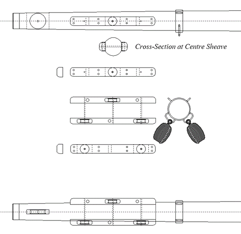
I am also trying to determine how to make the reefing combs (those conformal fittings I referred to earlier) - see the attached. At 1:72 these are only 1.5mm deep so a little fiddly to make - still thinking on the 'how' for now. These were used to rig the reefing pendants. One end was led through the hole opposite it associated sheave and stoppered with a knot, the pendant was then rove through it associated reefing cringle and down through the sheave. The tail was then worked with a reefing tackle as required when reefing the fore-and-aft sail.
The attached is my CAD drawing of the outer end of the main boom. It shows the combs and the spiderband, and the outer sheave. There is also an iron band on the very end/tip of the boom.
cheers
Pat
-
Hi Allan, I think this is probably Microsoft trying to fix/patch some of their security issues by restricting some macro operations. I remember some time back I had to load and keep using flash or the like to keep older macros active., but MS doesn't like that either. I know I am having issues trying to use macros I created for use in MS Word. I just opened a version of the spreadsheet using Excell (using the latest version of Excel in MS 360) that I had downloaded years ago and there was no issue. I haven't tried opening from the Database yet.
cheers
Pat
-
On 8/7/2023 at 11:35 AM, Jaager said:
I think that Desmond describes a different species of wooden ships. The 1850s were the end of a long era of guild style shipwrights. It seems like there is a wall not too much later. The main stream changed to composite and then iron and steel. The generation to generation chain of passing of knowledge about wooden ship building was probably broken - except for minor and independent yards. The old lofting methods replaced with a translation of iron and steel lofting over to wood. The lofting of every frame was a new practice - taken from metal methods - metal is not open to variation on the fly.
The all bends with intervening spaces equal to the bends in width was new. I would not trust Desmond to be relevant to any ship built before 1900 or so.
That is a very interesting point you make. I will need to reconsider this, but I may be missing a point you are making here. When designing this ship, Oliver Lang did not conform with the old/traditional methods of building a ship; he was of the new generation (not the Guild I believe - his father certainly was). For example, for the Victoria he used diagonal planking (to his plan which was based on a system he developed from a Devonport boat builder), he also used an Aberdeen style (clipper) bow, and a non-lifting screw design (first fit of this 'differential screw' design by Maudslay, fitted in any warship). The hull skeleton, especially aft, I think may have been quite different to the traditional more squared and spaced framing.
Desmond, and also ESTEP (1918), describe the building of "Wooden Ships" and, if I recall correctly, do sometimes refer back (within their text) to pre-turn-of-the-century techniques, and their descriptions do not appear to refer to the use of iron and timber in composite form for the stern timbers (that I have found so far at least). I have not read them extensively yet, but I have not seen any reference to composite, rather than wooden building technique?
All that said, I only raise these points to gain a better understanding, and you are probably right. I just need to get a better understanding of the points you make to establish whether to use these authors or not. Certainly, Oliver Lang in designing this one-of-a-kind vessel, used it as an opportunity to show the Admiralty some alternative building principles. Victoria was certainly unique for her time, and while she looked, and was armed, similar to contemporary Gun Despatch vessels (Arrow and Vigilance Class) she was framed/built on an entirely different principle that made extensive use of iron knees, hangers, etc, but she was not a composite build. She was also equipped with many different equipment designs such that I am at a loss to try and even make an educated guess of how her stern timbers were arranged and fixed. From the imagery, and the Builder's Certificate, she certainly had an elliptical stern and the knuckle line also appears more rounded than the traditionally framed sterns.
cheers
Pat


HMCSS Victoria 1855 by BANYAN - 1:72
in - Build logs for subjects built 1851 - 1900
Posted
Hi Grant, sorry I missed your question. If you are OK with it, I'll get back to you once I am happy with one as I don't want to lead people astray if it doesn't work.
cheers
Pat