


BANYAN
-
Posts
5,537 -
Joined
-
Last visited
Content Type
Profiles
Forums
Gallery
Events
Posts posted by BANYAN
-
-
I love this model Steven, especially in her quasi-diorama - a very nicely displayed model. Hopefully you won't accidently catch one of those protruding corners in her new home?
cheers
Pat
- tarbrush, mtaylor and Keith Black
-
 3
3
-
Those gripes/sea lashings look so good Eberhard, very nicely done. Now I have something to try and emulate for the Victoria's boats
") Can I be so bold as to ask for a link to that material for making them?
Can I be so bold as to ask for a link to that material for making them?
cheers
Pat
- Keith Black, FriedClams, mtaylor and 1 other
-
4
-
Hi Ron, I have a Sherline mill also. That chuck usually comes with a draw bar (threaded on one end and a bolt type head) that you put in from the top of the spindle assembly. I partially engage the thread of the draw bar into the chuck bore, give it a tap or two with a small rubber mallet (small hammer will work also) which usually disengages the tapered (morse) chuck head. If you don't have the draw bar, putting a metal rod of suitable OD down into the spindle bore and tapping that should also work, BUT put a rag or something under the chuck so that if it dislodges completely, it will fall onto a padded surface and not damage the cross-table or the chuck etc. The rod could be one of the many different bars/rods provided by Sherline, but should be a smaller OD than the bore, but bigger than the internally threaded bore in the top of the chuck (so that you don't drive the bar into this and damage the thread).
I hope that resolves the issue for you.
cheers
Pat
- rlb, thibaultron, Canute and 2 others
-
5
-
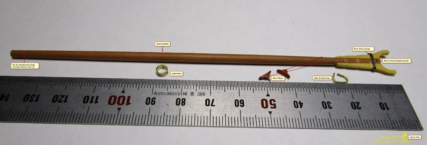
Hi Clovehitch. I had to do these for my build at 1:72 recently. I found I had to use very dense grained wood for any success. My method was to first file flats on either side of the boom inner end. To make the jaws I printed scaled copies of each jaw set as templates l(that is, the jaws as a full integrated piece).
I thicknessed the wood to the appropriate thickness, and pasted the paper template onto it; and double sided taped (low tack) a sacrificial thin piece of wood under it to keep a clean cut. I then cut these to the required shape following the outer lines. Once cut, I sliced these in half to get the individual jaw pieces and sanded the centre cut back to the required line (to allow for boom neck thickness and taper.
I removed the template but before separating the sacrificial piece away, I drilled holes at the required places to simulate the through bolts (leaving the sacrificial wood in place helps with protecting these thin pieces. I then removed the sacrificial piece and edge glued (two part epoxy for strength) to the flats on the neck being sure to keep them aligned.
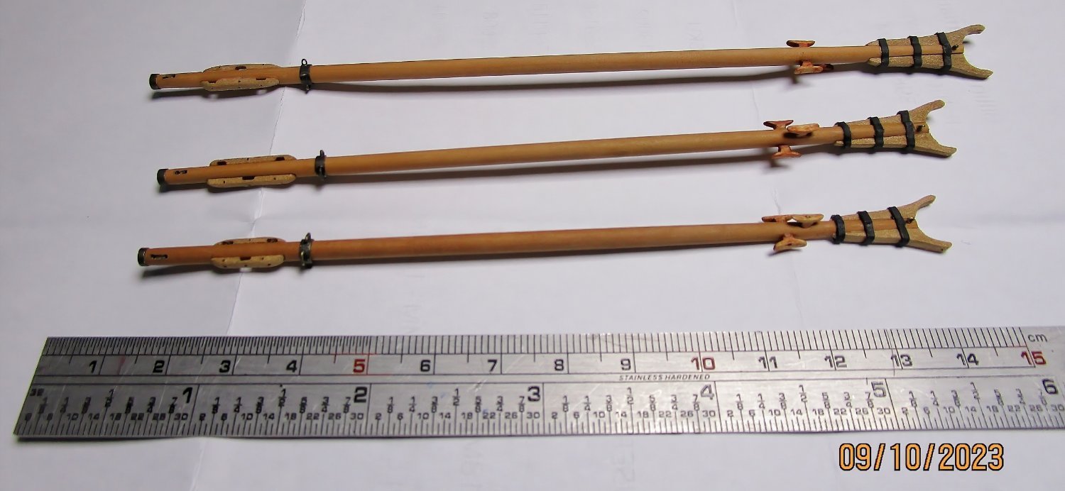
The following shows my test boom to prove the method and the final results. I hope this helps? The outer reefing combs look slightly large, but at this scale they are quite small and look better scaled to the naked eye.
cheers
Pat
Pat

-
21 hours ago, TBlack said:
That doesn't mean that we get to be like Keith, but it does mean we get to act like Keith.
Of so true Tom, a hard act to follow.
cheers
Pat
-
Your build is coming along very nicely Harry; looking good. WRT deck furniture, basically followed the dimensions given by Marquardt in his drawing (at scale) in his "Capt. Cook's Endeavour" Revised Edition. The exceptions being that I waited until I had placed the steering wheel and other deck equipment before making the skylight to fit.
cheers
Pat
-
-
Wow, .... simply WOW! I stand gob-smacked Chuck that looks so very realistic (and thanks for sharing your technique).
cheers
Pat
- mtaylor, FrankWouts and Ryland Craze
-
3
-
-
Doing a lot better than I ever could Steven; coming on very nicely.
cheers
Pat
- Louie da fly, Glen McGuire and mtaylor
-
2
-
 1
1
-
Might be slow progress John, but the result is great; looks very good mate.
cheers
Pat
- mtaylor and FriedClams
-
2
-
Looking good Keith; a few pointers (about the 'inside work' as you call it) that I can take away also - thanks.
cheers
Pat
- mtaylor, FriedClams, Keith Black and 3 others
-
5
-
1
-
Hi Richard. This is really nice work. I have been following along in the background (Stalking
), so I thought I had better post. This a very well constructed model and a very interesting subject for a model.
cheers
Pat
-
I like it Glen. Wouldn't the slight opaque finish simulate running (not agitated) water in the stream and mist anyway?
cheers
Pat
- mtaylor, Keith Black and Canute
-
3
-
Great progress Steven, a real little gem emerging.
cheers
Pat
- Louie da fly, Glen McGuire, Cathead and 1 other
-
3
-
1
-
-
Hi Ian, overall your build is looking great. One small point that may/may not bear further consideration is the motion/force of the bow wave on the verdigris seen on the ram. Would the leading edges of the ram be more 'clean'? I would not say polished as these would never have achieved sufficient speed to polish the edges. However would a gradient leading back from the leading edges be more realistic. That said, if the vessel had been alongside for a while this gradient would be gone but more salt/barnacles seen. Only offering this as you asked
and may be a little OTT.
cheers
Pat
-
I can only reiterate earlier comments that hopefully your run of bad luck is well and truly behind you. It is a testament to your attitude to life that all of this has not brought you down and that you maintain a positive outlook. Good luck with the article.
cheers
Pat
-
-
Great to see the use of modern technologies in improving our hobby Ian. Looking very good.
cheers
Pat
- Glen McGuire and Ian_Grant
-
1
-
1
-
Very nice work Steven, that very much looks like salt water bleached wood.
cheers
Pat
- mtaylor and Glen McGuire
-
2
-
Ditto Keith; those simulated chain stays look great.
cheers
Pat
- FriedClams, mtaylor and Keith Black
-
3
-
-
Ditto Ferrus Manus
cheers
Pat
- mtaylor, Glen McGuire, Bryan Woods and 2 others
-
3
-
2

Mary Rose by Baker - scale 1/50 - "Your Noblest Shippe"
in - Build logs for subjects built 1501 - 1750
Posted
Oh so true!
cheers
Pat