


FlyingFish
-
Posts
470 -
Joined
-
Last visited
Content Type
Profiles
Forums
Gallery
Events
Posts posted by FlyingFish
-
-
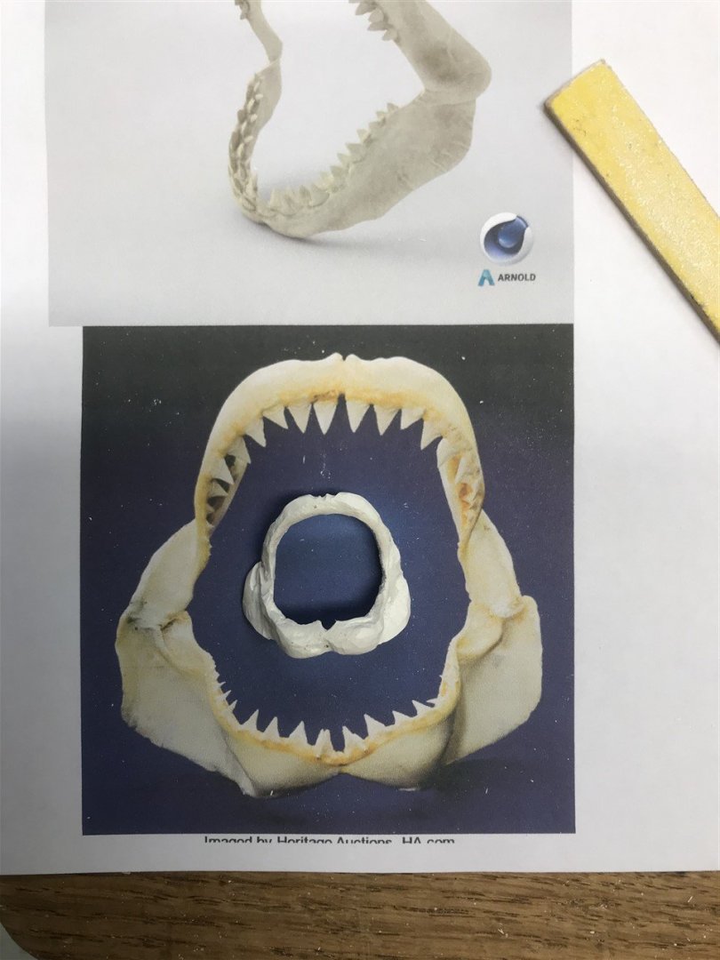
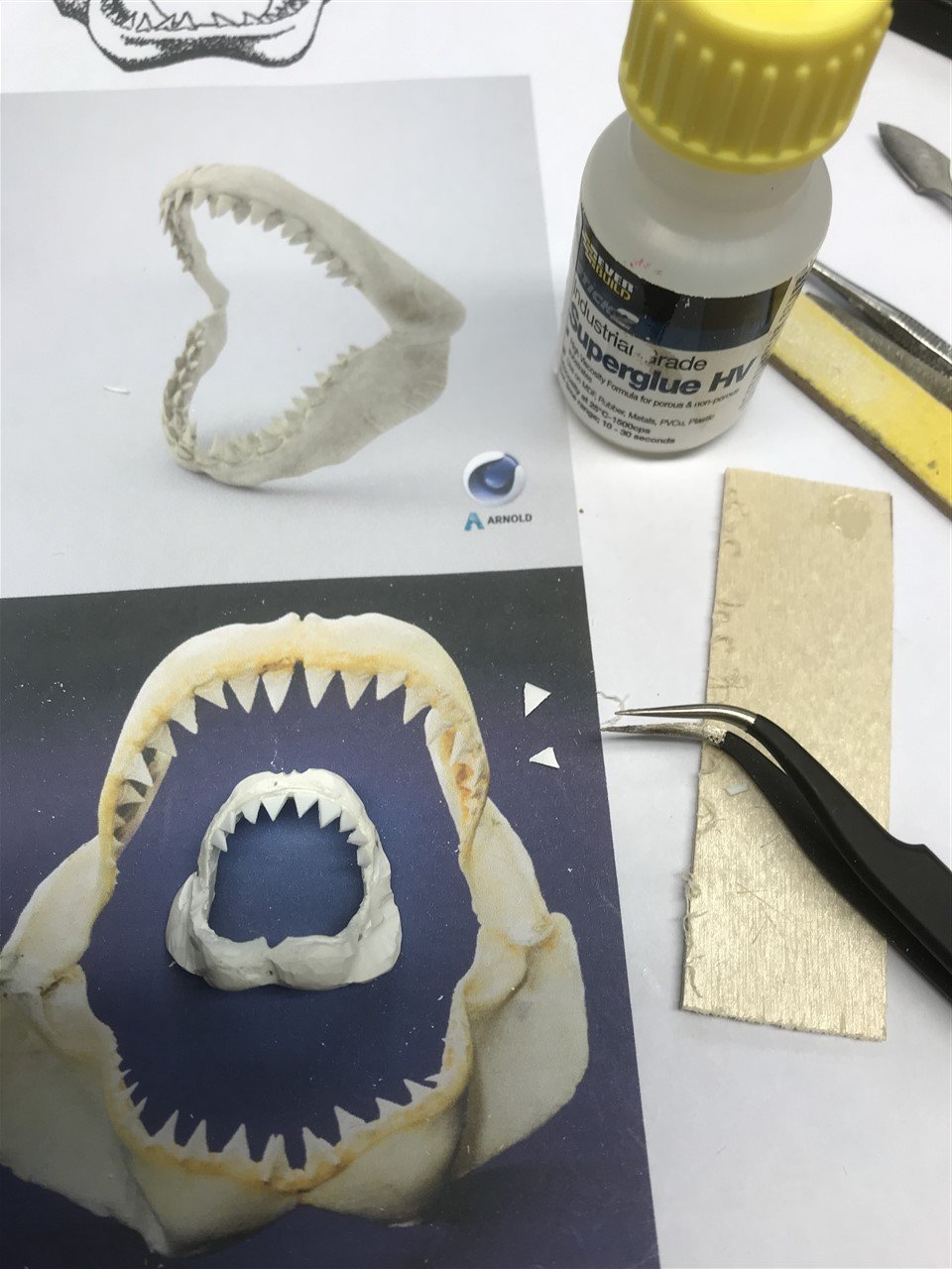
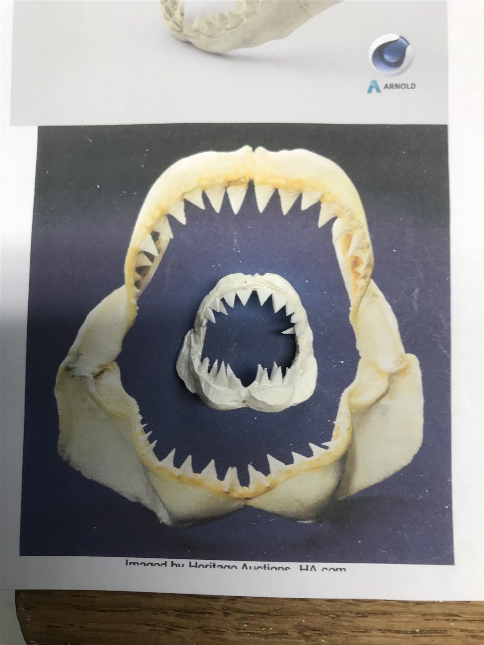
A small diversion...
Need some jaws....

So this is a scratch build right?
Milliput to the rescue. Soft copper rod soldered to shape and a rough daub of epoxy.

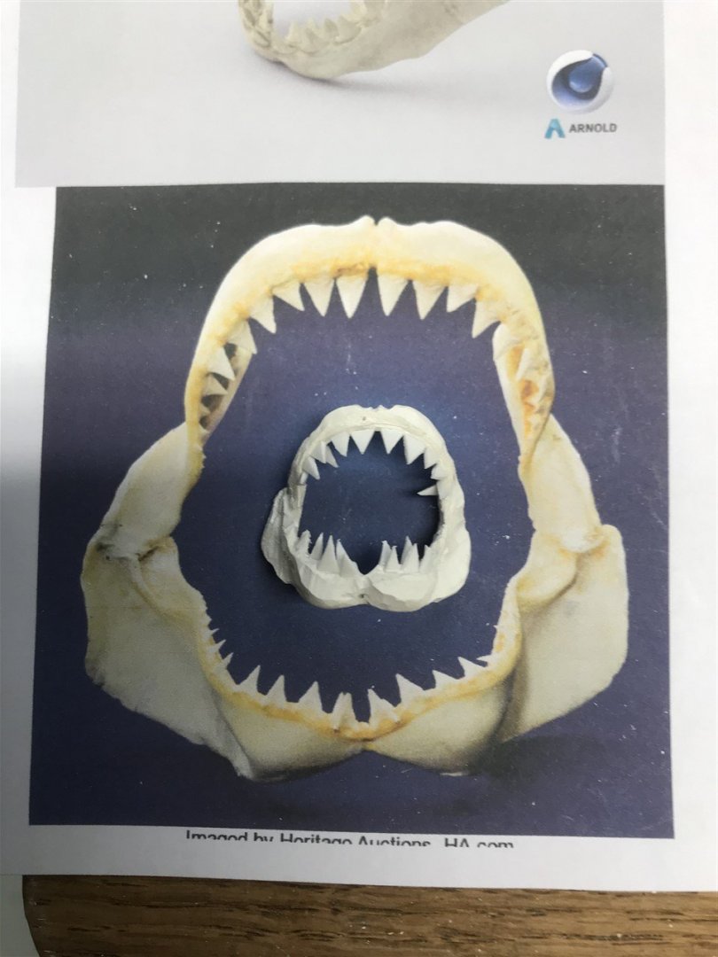
Bit o' sanding...
Trip to the dentist...

Cosmetics..
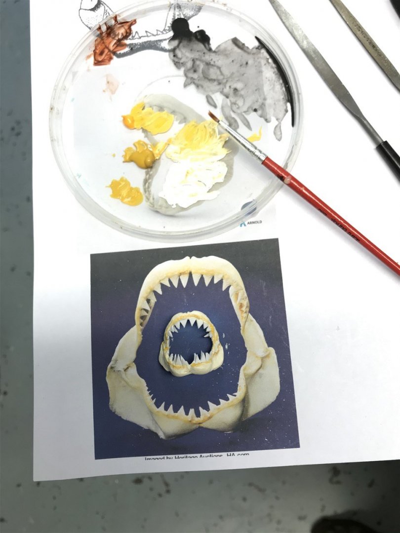
A little root canal work and tidying up...
Well it's a start... think I can go from here to something like the original later on.
- Rik Thistle, mtaylor, GrandpaPhil and 2 others
-
 4
4
-
 1
1
-
I have to sit down to read your log. Humbled.
- Keith Black and Bitao
-
1
-
1
-
Gobsmackingly, nay pearl-clutchingly good work. Must get a mill, but then I'd have no excuse.
- druxey, KeithAug, Keith Black and 1 other
-
4
-
Thanks to all for the thumbs up - welcome onboard GrandpaPhil!
-
Short Beams 'n Carlins.

Time to start framing out the superstructure and bulkheads.
Lower trunk cabin:

Side decks dry fitted, and Pilot House frame started:


-
-
Very shapely; good job Vaddoc!
- vaddoc, FriedClams and bruce d
-
3
-
-
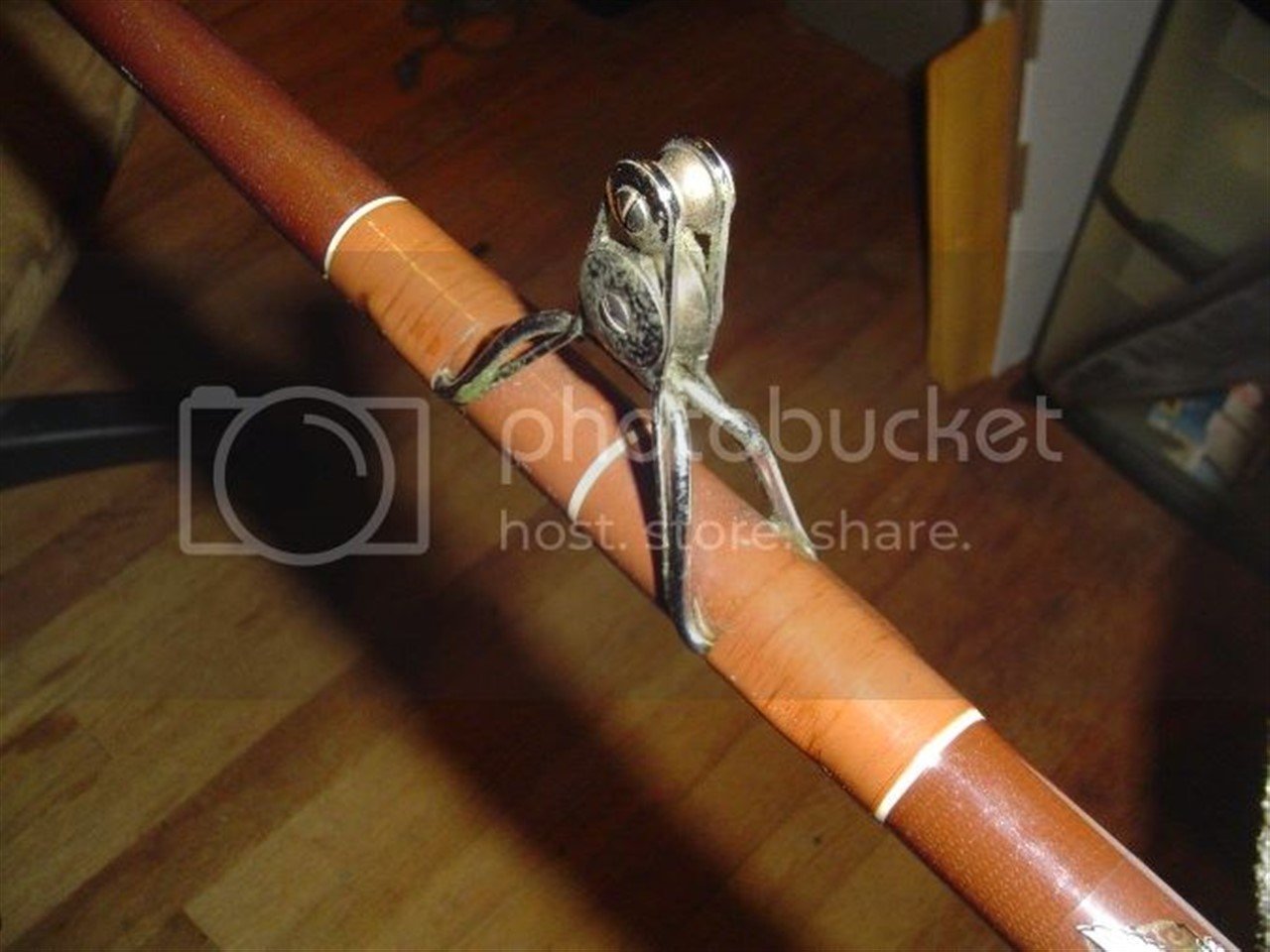
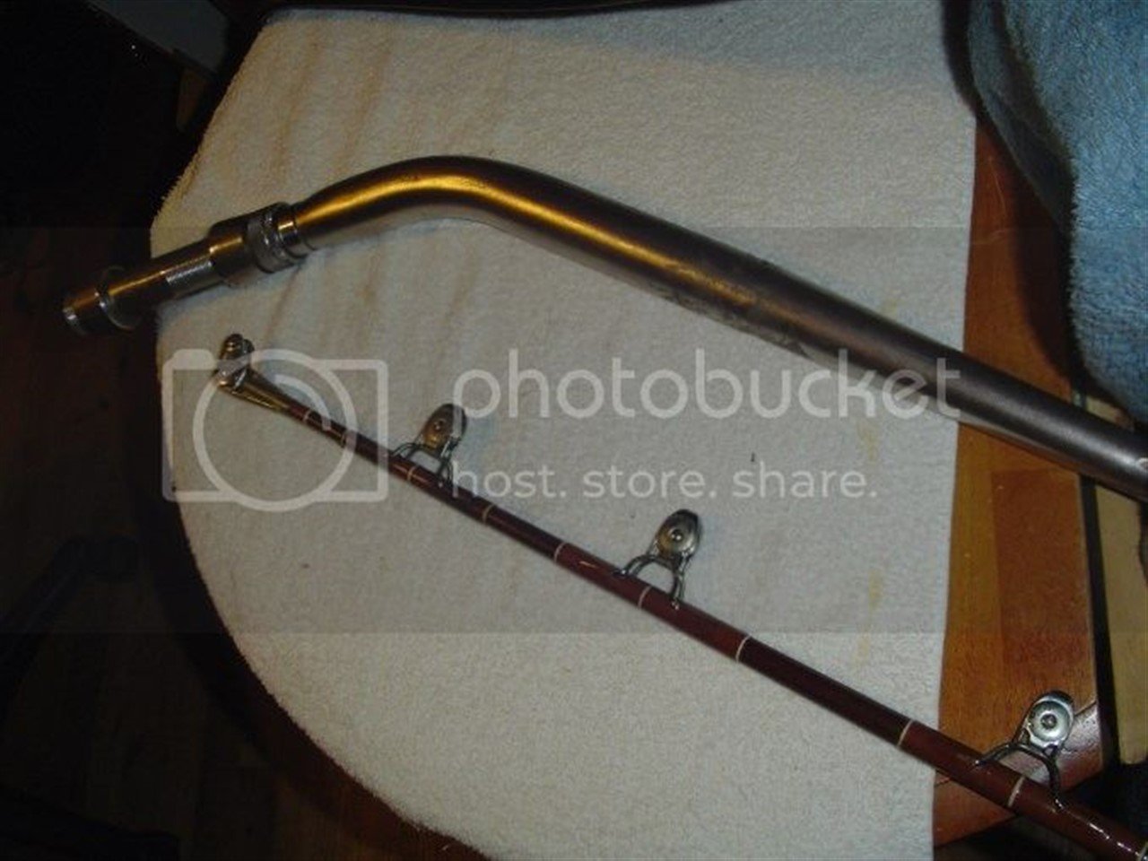
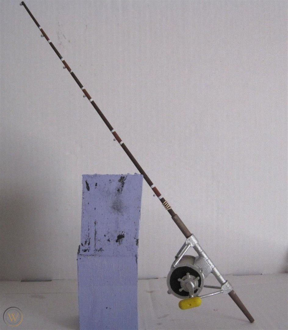
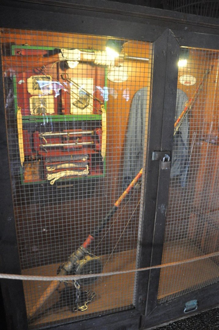
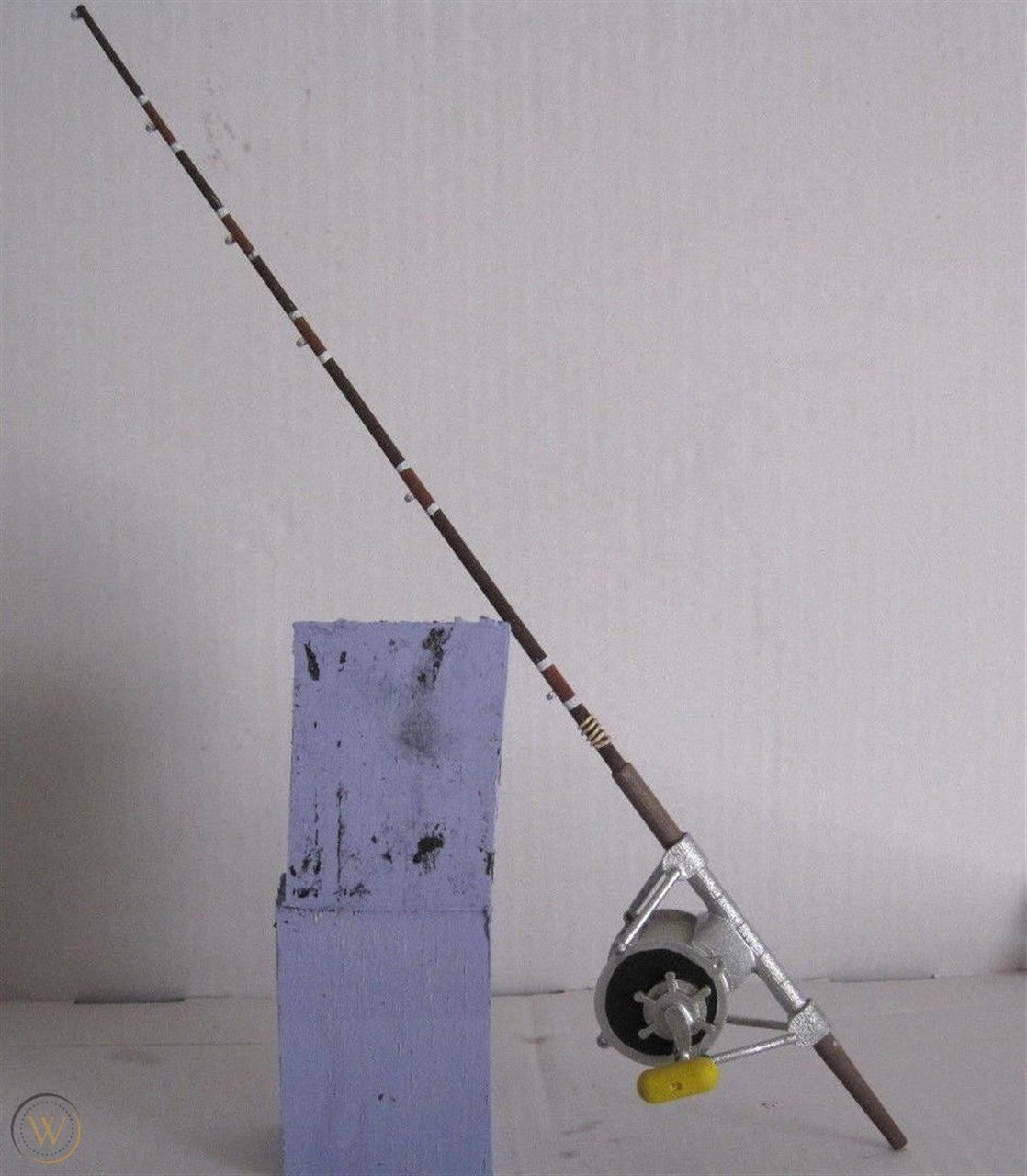
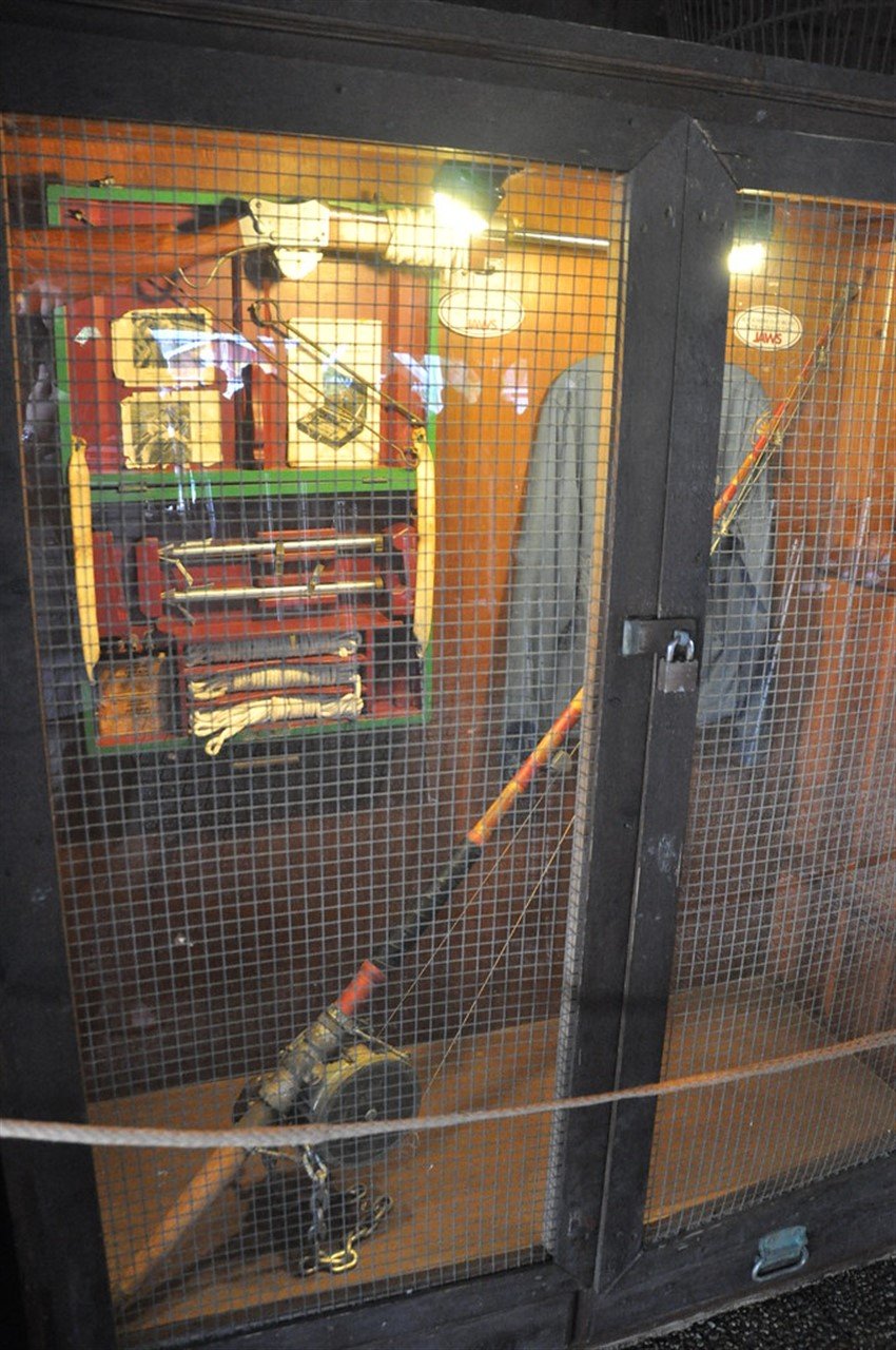
It was a fenwick 130 big game rod with a wooden butt, and varmac reel seat with a 16/0 Senator reel, . The one shown at universal studios in a glass cabinet (pics on internet) is not accurate.
See attached, and also this link has plenty of images of the correct rod.
Have fun!
-
I have some info and pics of the rod if it's any use?
-
-
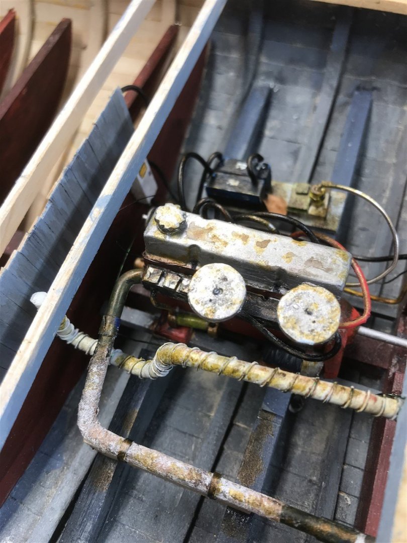
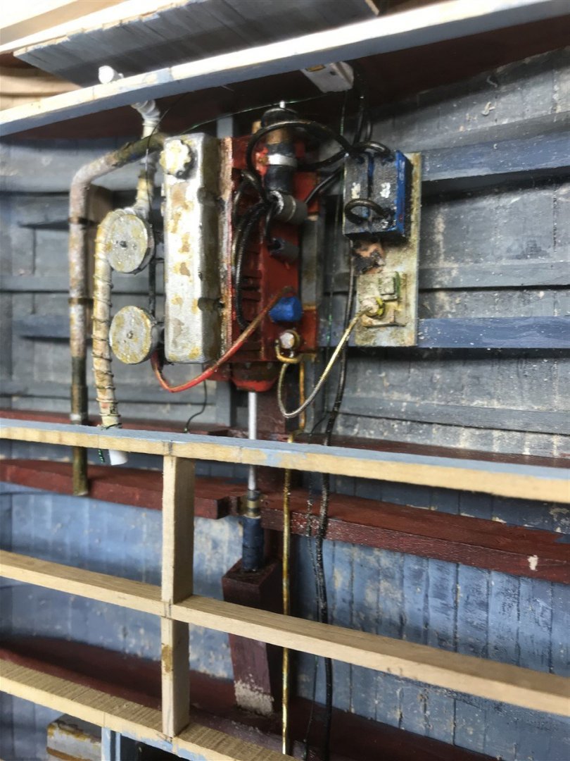
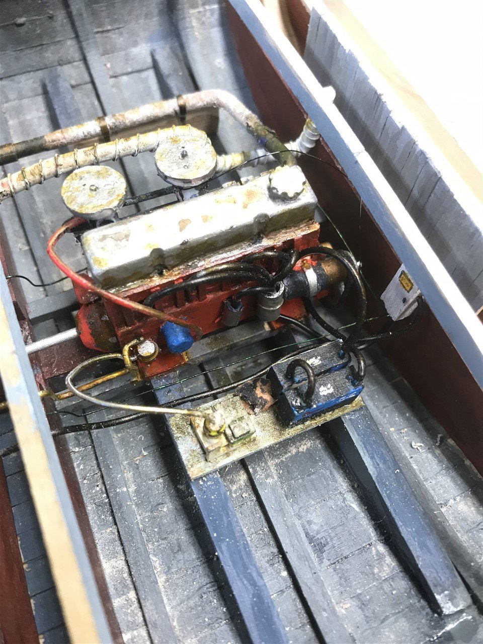
Few extra pics of the engine and rudder controls before I cover them up...

-
Rudder and prop
I have this reference of Orca' prop and rudder thanks to jlt13th...
Three bladed left-handed prop, and a welded rudder on a shaft, where the bottom bearing is through a plate bolted to the keel and extending beyond the rear of the keel itself. It looks a bit fragile to me.
The figure gives a sense of scale, and proportion.
I was going to make the prop, but I don’t have a lathe or mill, and making it out of plastic would probably be hard to get right. So until I can face shelling out £20 for the right one, I have a four blade prop in place for the moment.
The rudder was probably made in house like this one..
...and fitted like this:
I am a very poor metalworker, but managed to cobble one together:
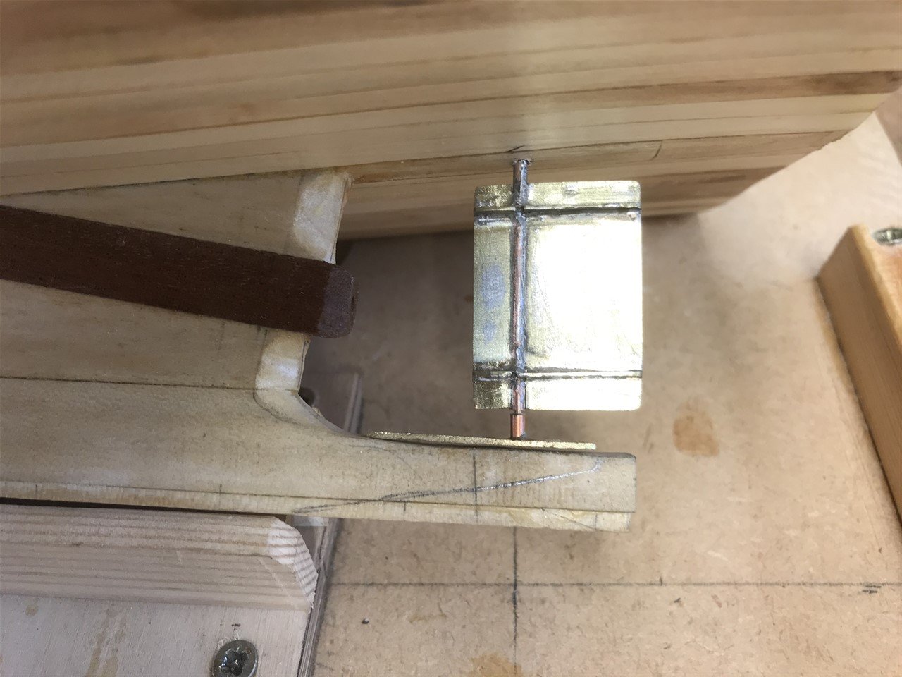
Rudder needs a sacrificial anode; the keel needs shortening, the keelson shaped, and things tidied up a little yet, but the proportions are getting there.
- KeithAug, Rik Thistle, GrandpaPhil and 1 other
-
4
-
Lots of good fiddly bits there! It's looking very authentic. You look as if you are almost done - love the lager cans! Fighting chair?
- Rik Thistle and neilm
-
2
-
Me too - an interesting project!
- Wintergreen and raysven
-
2
-
-
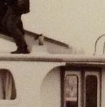
Looking again, I think they removed the overhang of the roof back to the cabin wall, so the pipe had to be moved.
-
No sign of the original exhaust here (ladder not yet moved in this pic) - they must have rebuilt the pilot house roof or blanked it off.
-
Well spotted hawkeye! Yes I see it now in this pic too.
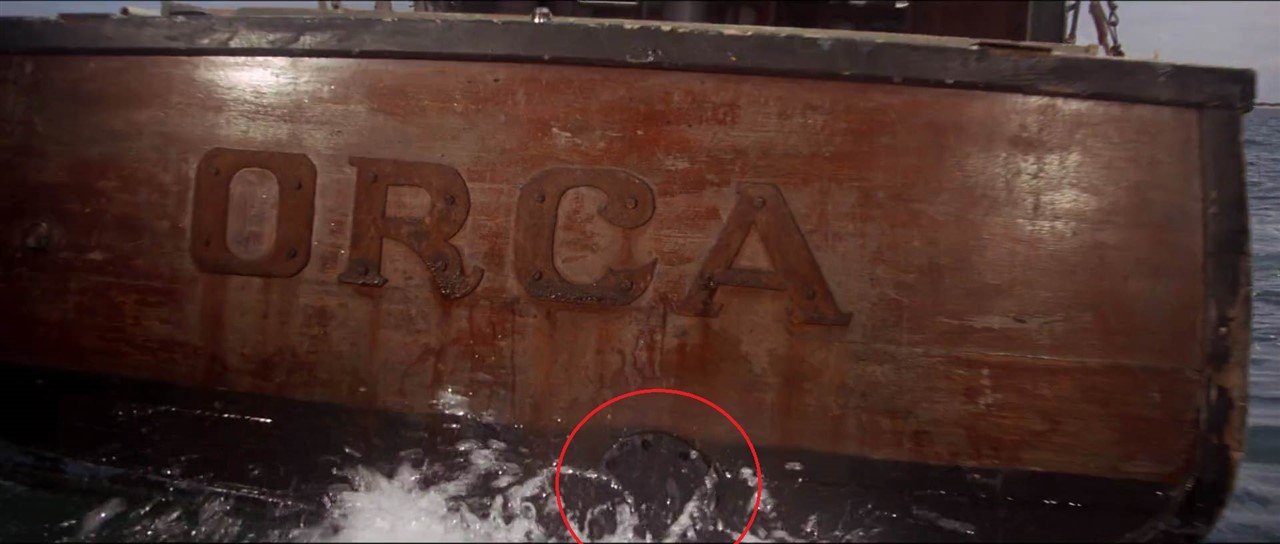
So the blank on the transom is a mystery.
-
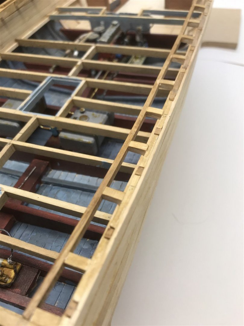
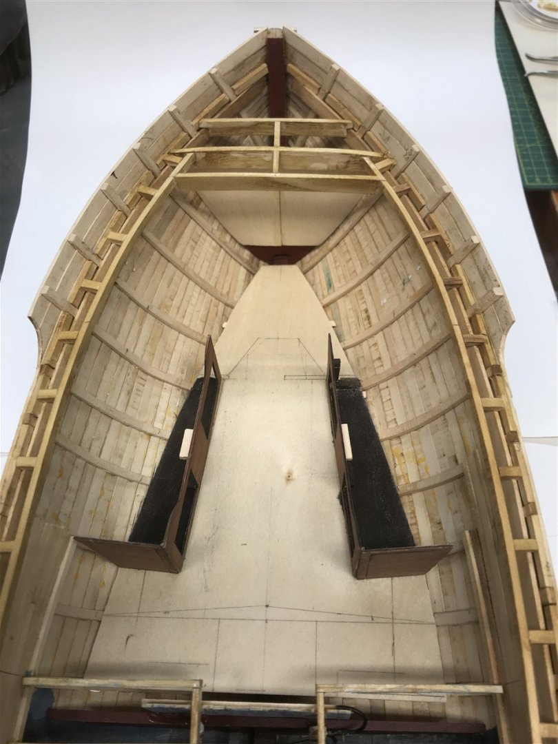
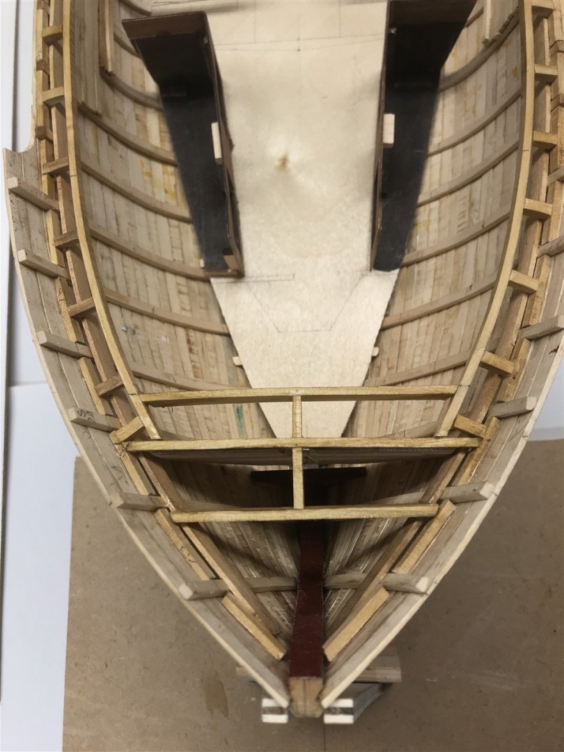
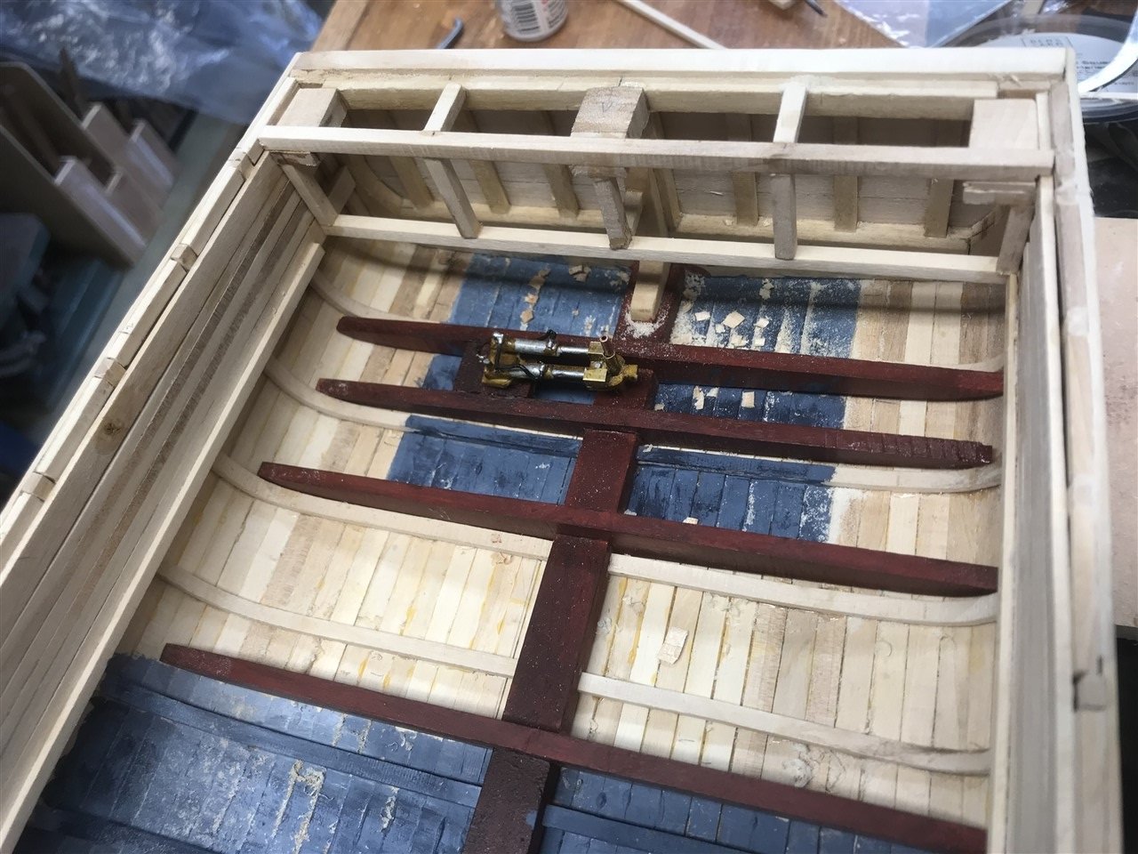
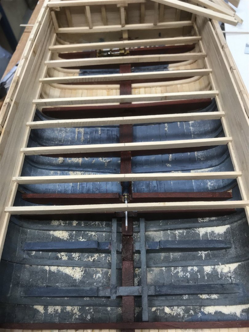
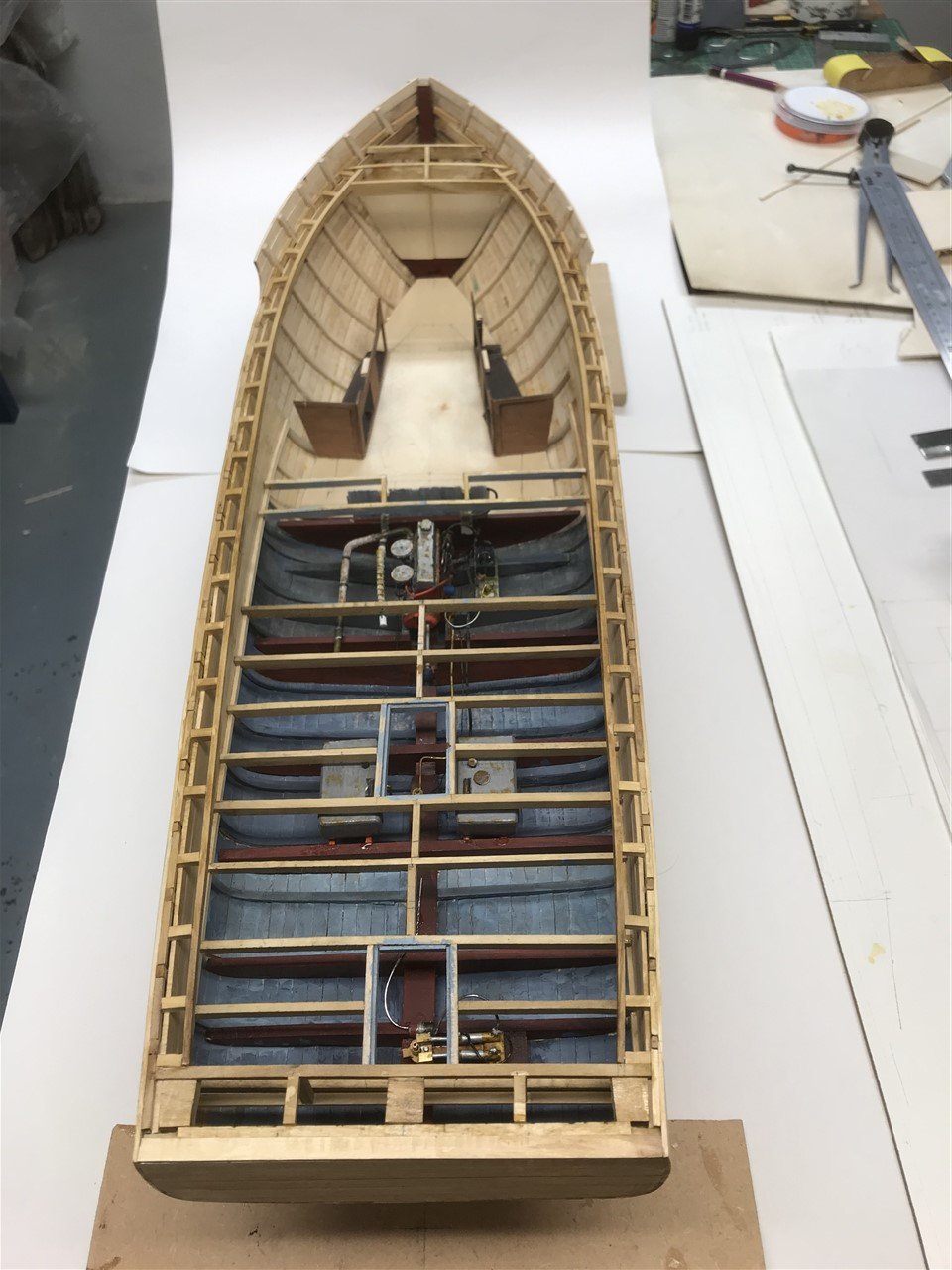
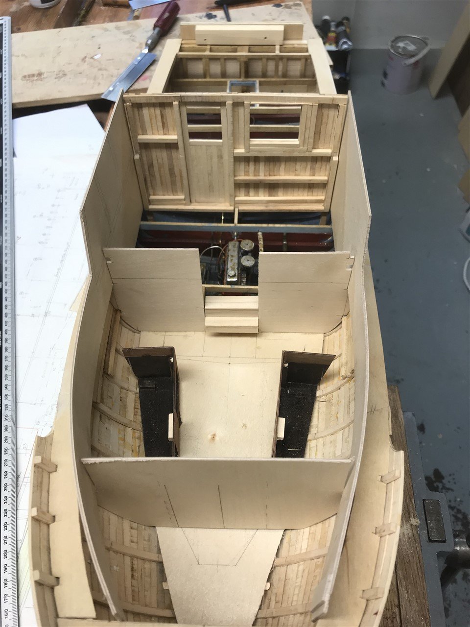
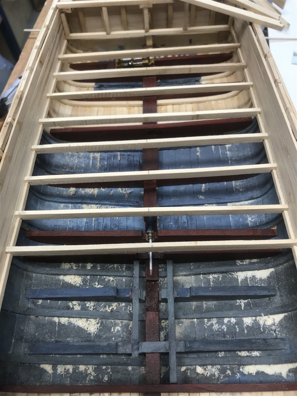
Floors; Stringers; Sheer clamps; short beams and carlins….
If you are interested in the design detail read on, or if not, skip to the build pictures!
The next step is to complete all the below-decks structures, before the side and main deck planking and superstructure.
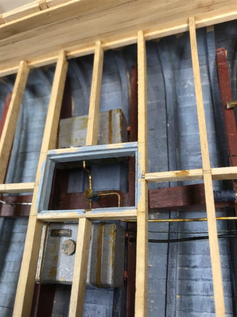
Working up from the keel, the floors below the pilot house form the bearing for the engine; and further aft the fuel tank; exhaust pipes (more of which later); rudder control and hydraulics.
These details will be added where they show through open hatches in the deck, otherwise omitted.
It’s likely that some bronze floor strengthened the hull as well.
A stringer supports the deck beams. The beams are visible when the engine & stuffing box hatches are open.
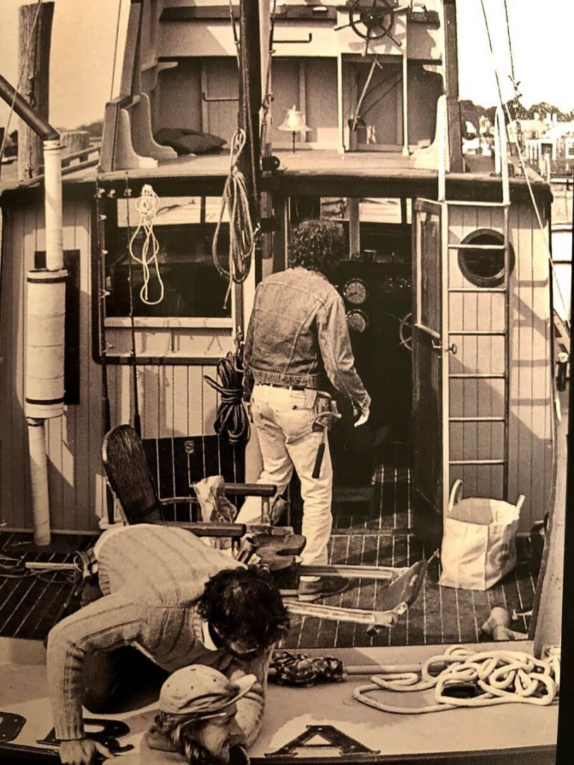
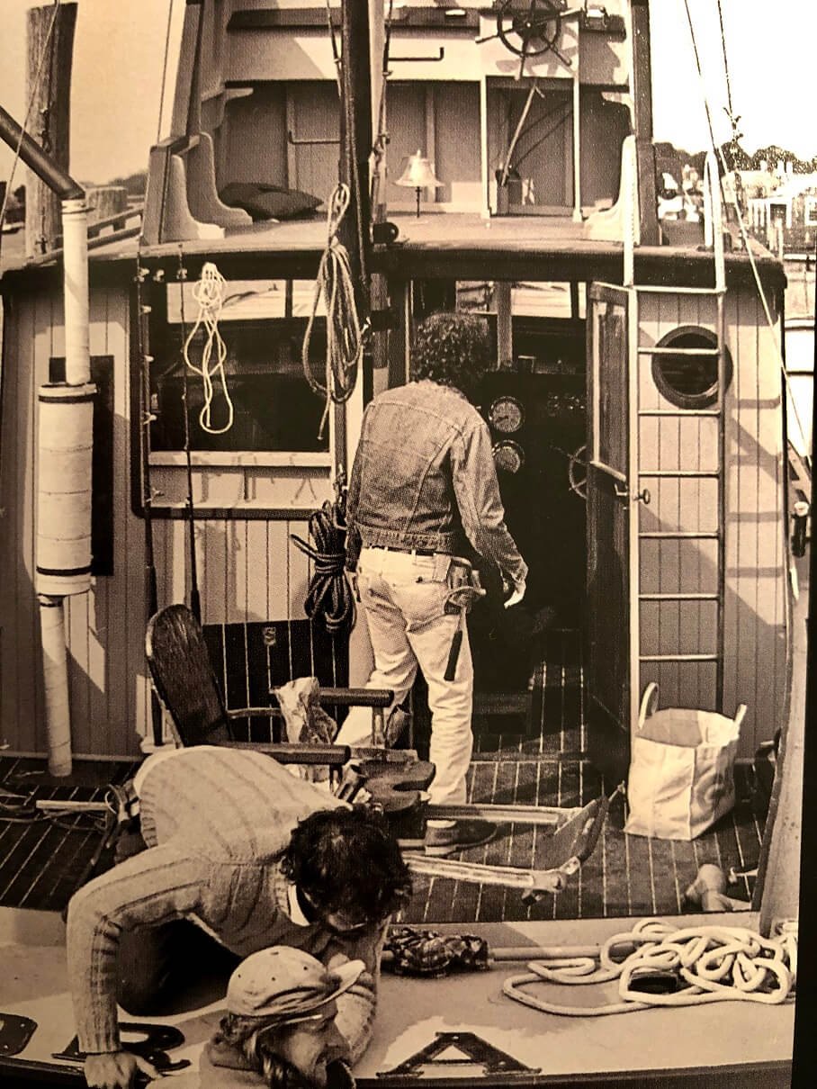
The floor height is not easy to measure, with confusing images from the film. As there is no pilot house step the engine sits entirely below decks, so there must be room enough to get the engine between the keel and the beams.
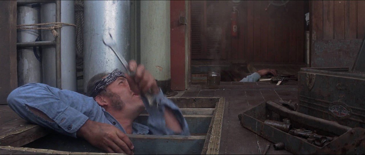
The movie still shown suggests Quint and hooper have room to stand – hardly likely as it must have been a tight squeeze.
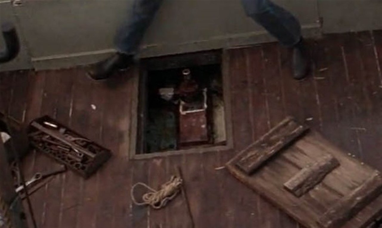
The image of the rudder hatch open shows no space below the deck, the hook/keel and rudder shaft being just below the deck… hmmm.
Direct measuring of stills suggests the decking is 28 -30” below the sheer line at the transom, with the coaming adding another 4”. The coaming rises forward. This gives just enough room for a very small engine below the pilot house deck.
It was at this point that I realised I had made two errors by overestimating the space below decks when making the engine, compounded by over scaling the engine which has now been replaced with a smaller one. Less haste; more speed!
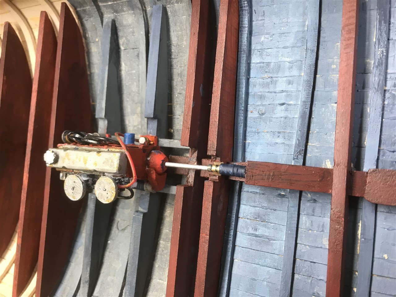
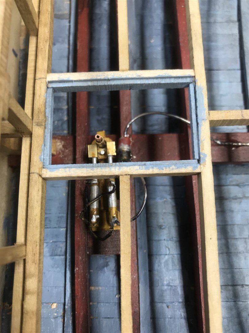
Below decks were painted a dirty duck egg blue, darker for the deck beams.
This is the rudder control as modelled.
As an aside, the original ‘Warlock’ had a wet exhaust system exiting just above the transom waterline. However, ‘Orca’ was changed for filming to a dry exhaust and stack on the port side of the aft deck. Maybe because the cloud of steam/fumes at the transom would get in the way of filming, and it looks more in keeping with Quint’s character. I assume this was functional, although it may have been a prop connected to a smoke generator; who knows?
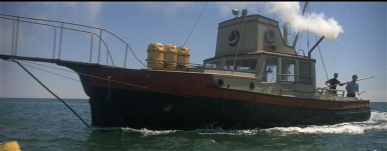
The old wet exhaust has a plate screwed over it, as shown on the left. Therefore, the old gooseneck inside the transom trunking, muffler, and pipes back to the engine are not modelled.
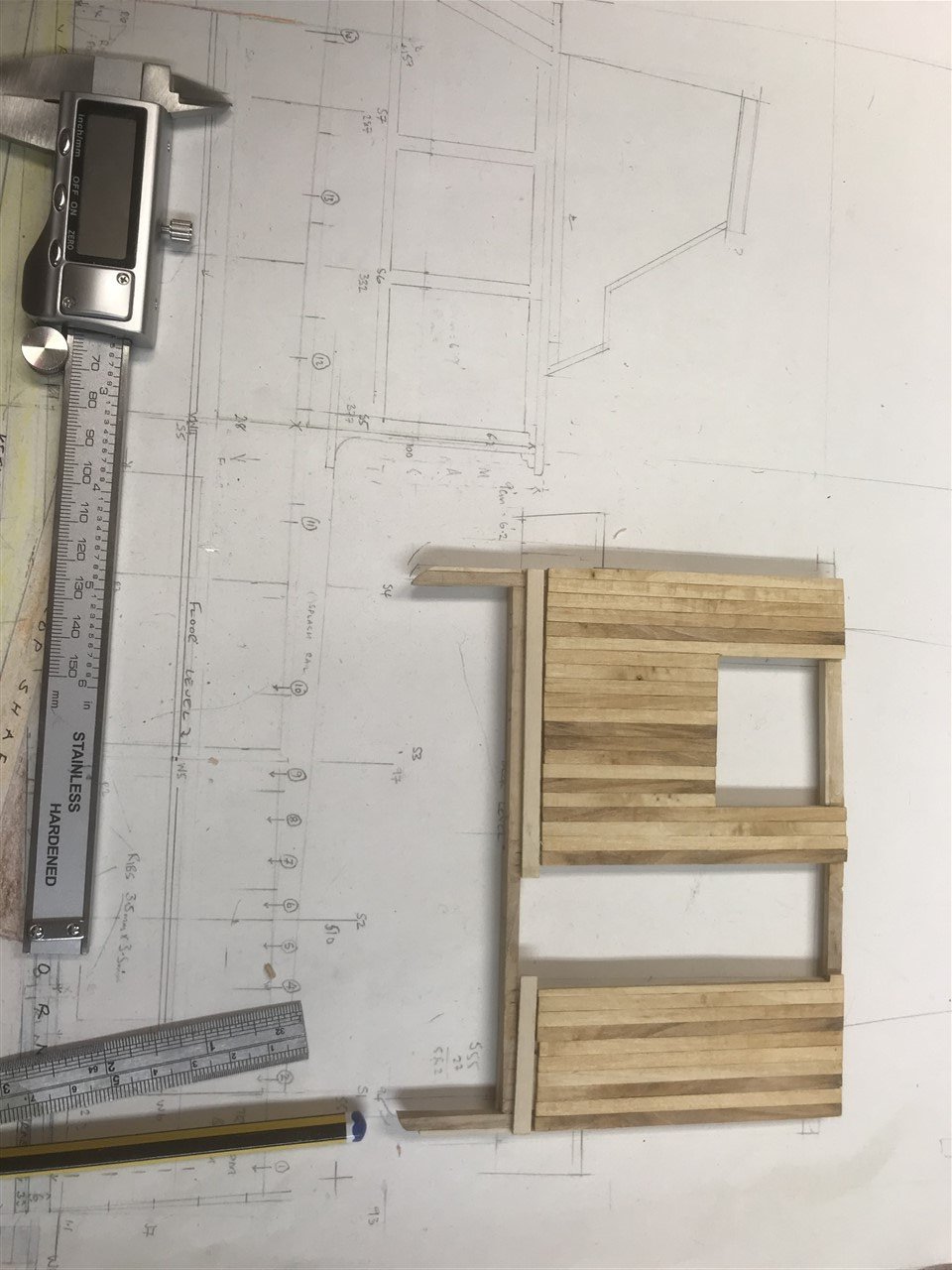
The lower trunk cabin is the least known part of the boat – the few stills that exist are confusing. There are some pencil sketches online, but these may well be best guesses at the layout.
It serves as a place for Hooper to stow his various bits of kit, radio tags, scuba kit and shark lance and poison. We see Quint retrieving the machete and harpoon gun, and later lifejackets.
Rather than get bogged down with this, I’ll build what is known, and the rest will be as you might expect to find in a lobster boat of this size. I’m sure if I make mistakes someone will eventually correct me. In any event if can only be glimpsed through the access hatch and the portholes.
Once this is all in place, then the main outside decking and pilot house decking can go ahead.
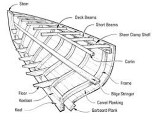
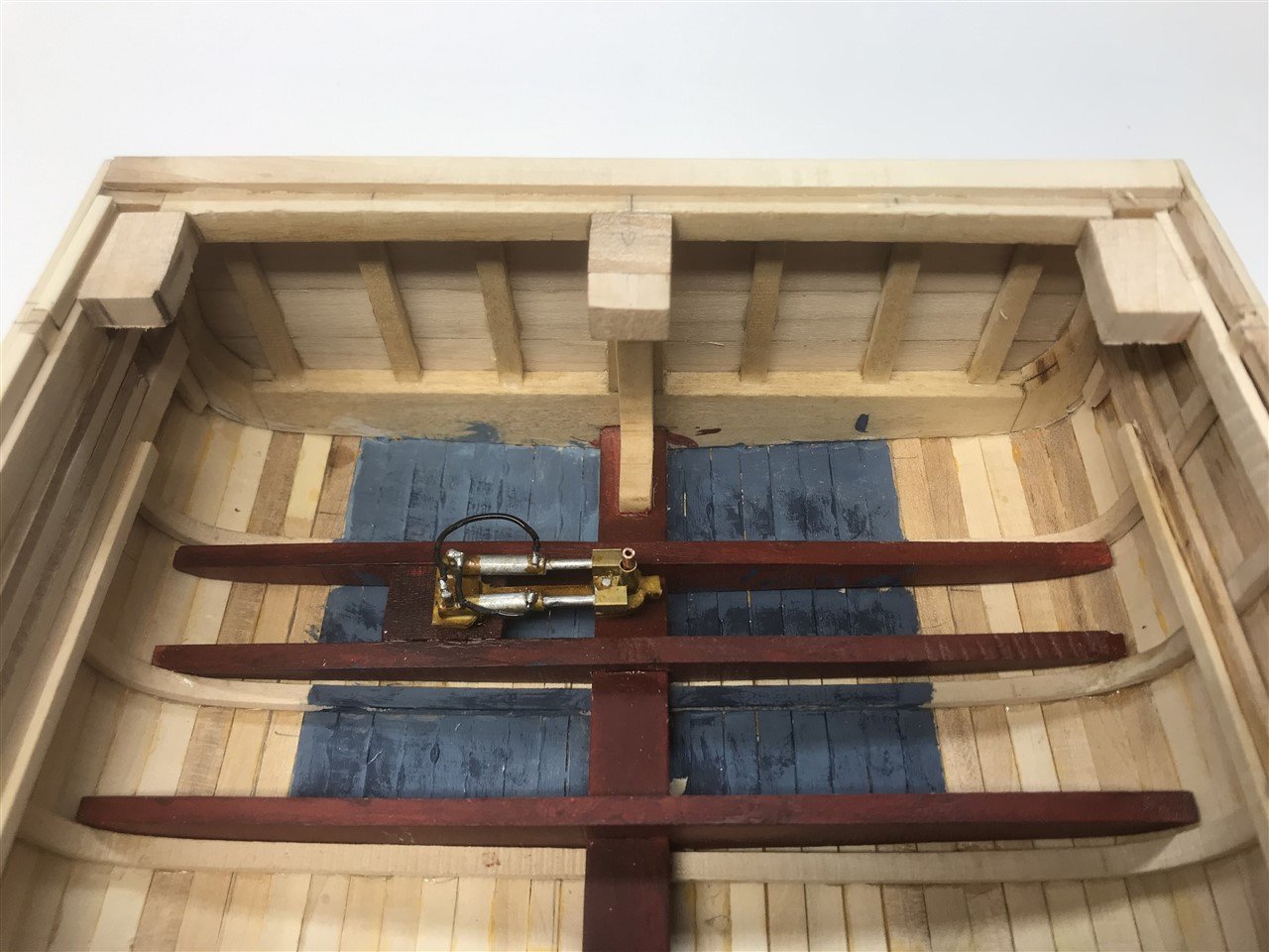
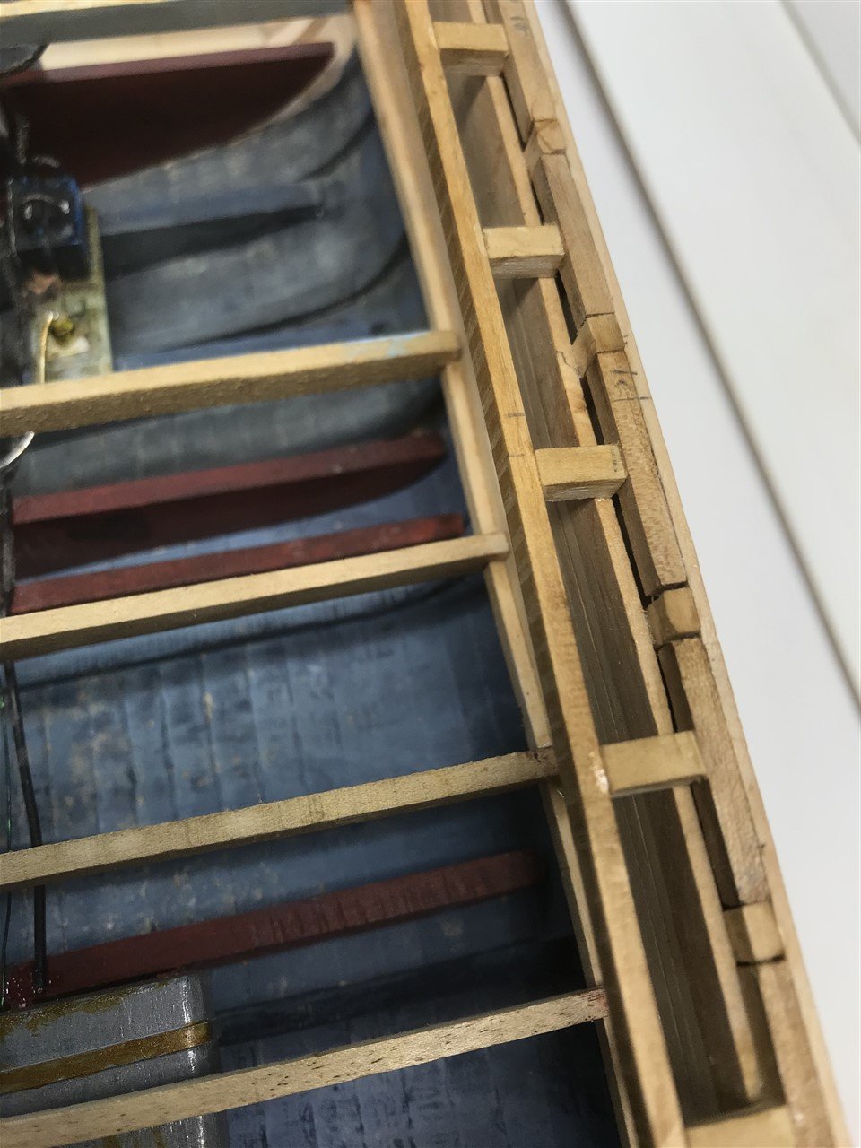
The construction of the short beams looks like this example:
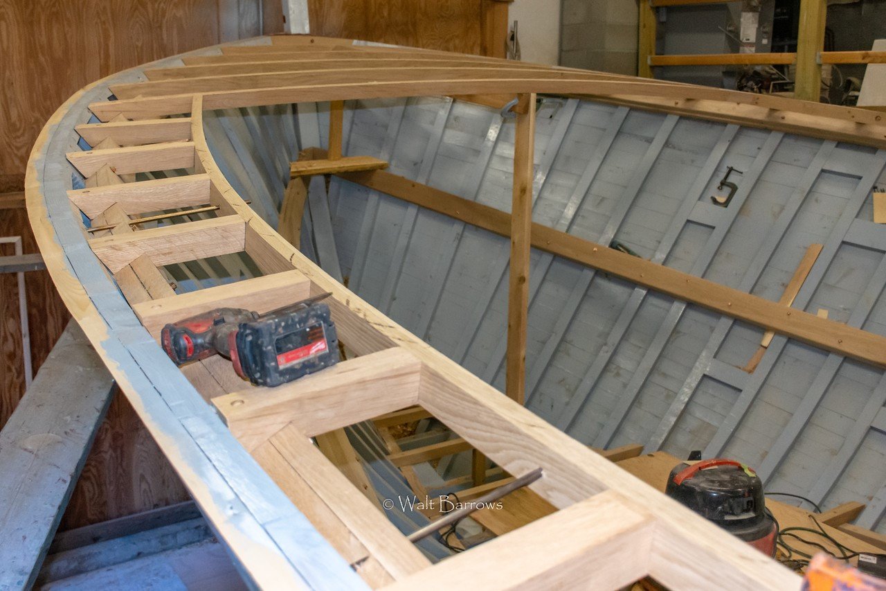
This requires a sheer clamp shelf, and short beams to a carlin, all planked below and above. Side decks are probably ply, or ply over planking at the transom. This will be faithfully copied.
Enough of the talking, the shipyard hooter just sounded. I'm off to joint the chippies in the bar.
- KeithAug and GrandpaPhil
-
2
-
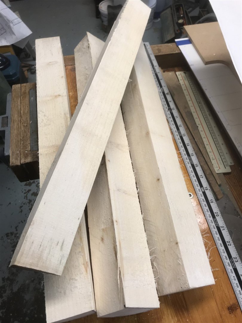
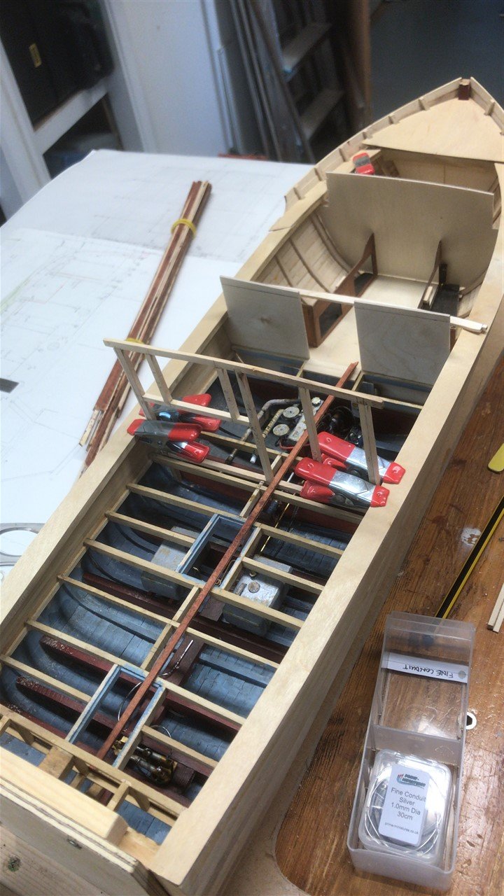
Yes, as I thought. The carpenters have been in and made a right old mess.
Left wood all over the place then gone off for a beer. Typical chippies.
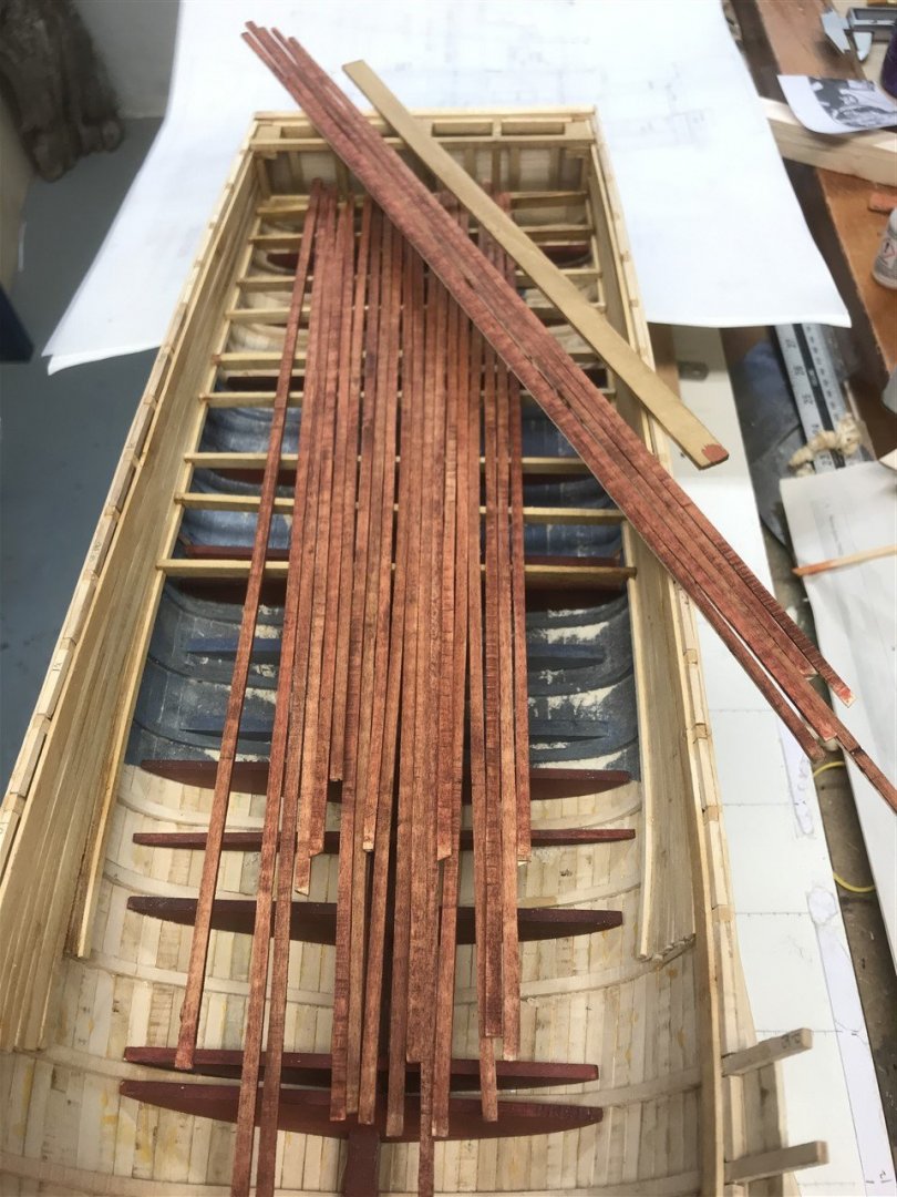
Must mean a bit more planking shortly.
")
- KeithAug and GrandpaPhil
-
2
-
Seems like a fresh batch of timber is on it's way...
-
On 4/7/2021 at 12:52 PM, neilm said:
Keep posting please.
Suggest you start a build log DCN - we can help each other then!
-


Orca by FlyingFish – FINISHED - Scale 1:20 - from the movie Jaws.
in - Build logs for subjects built 1901 - Present Day
Posted · Edited by FlyingFish
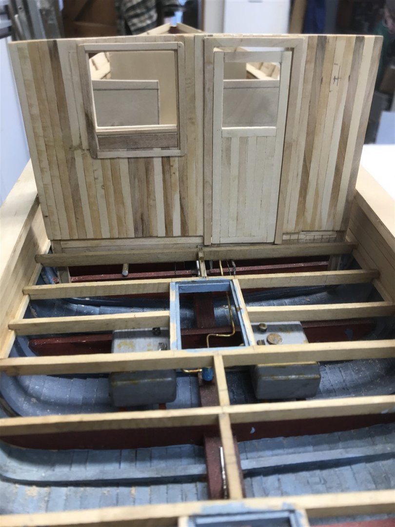
Superstructure progress...
Lower trunk cabin making progress - needs dressing up, but getting there.