


DocBlake
-
Posts
1,811 -
Joined
-
Last visited
Content Type
Profiles
Forums
Gallery
Events
Posts posted by DocBlake
-
-
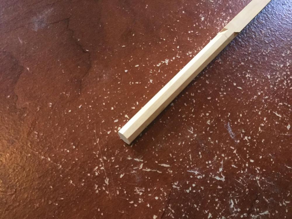
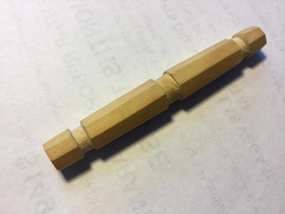
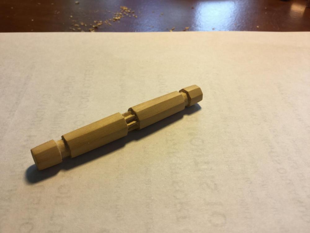
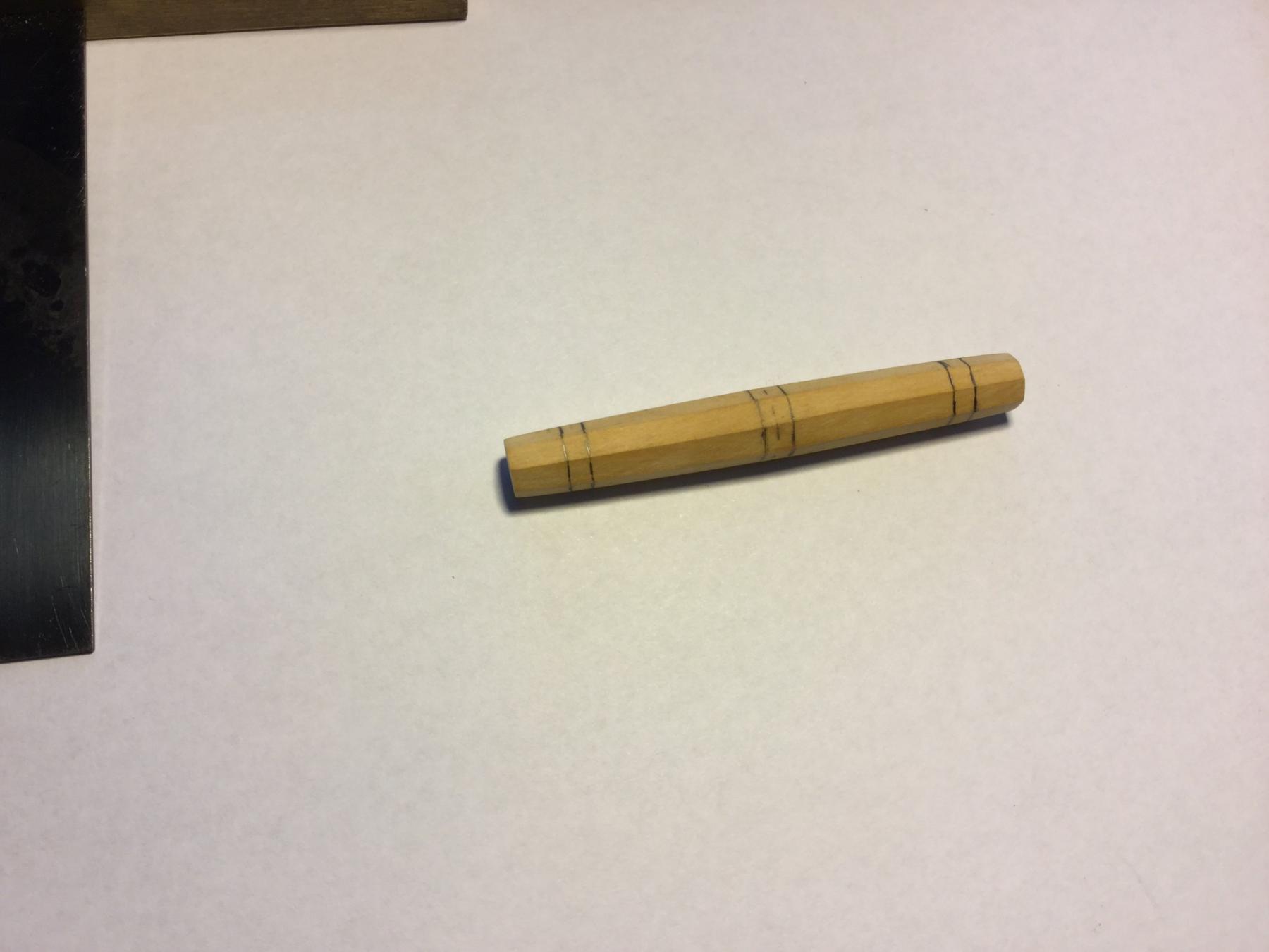
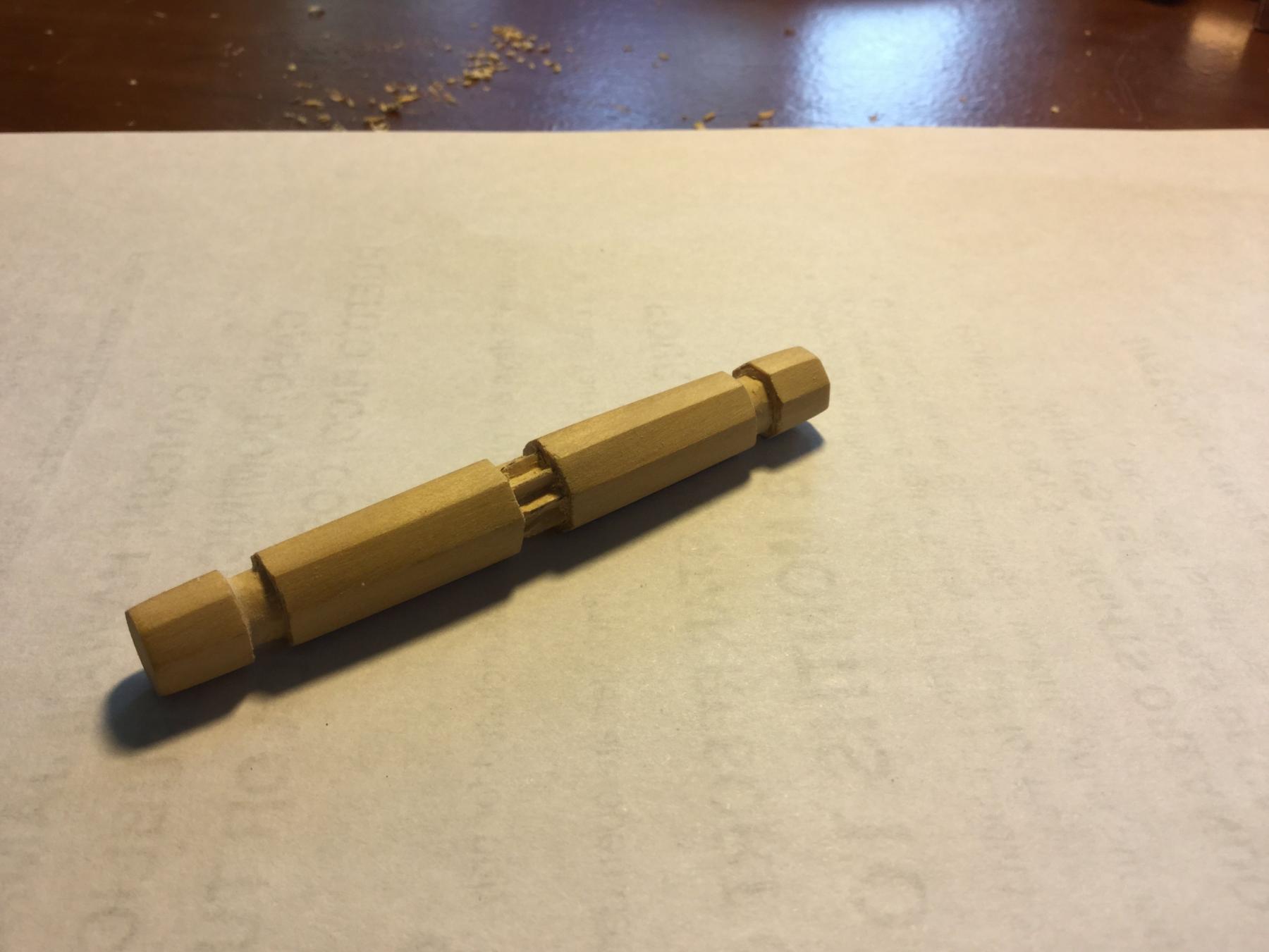
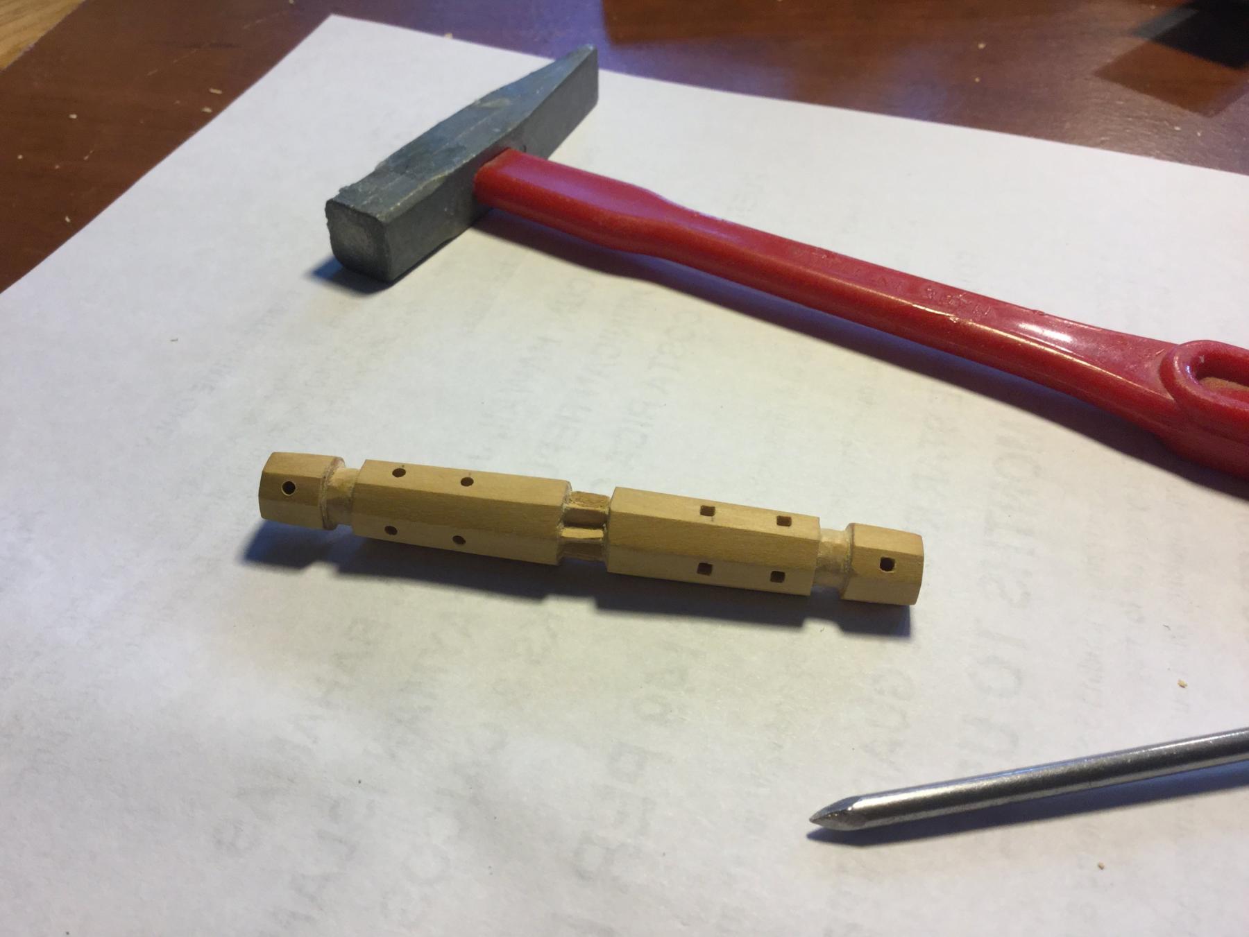
Here is a series of photos showing how I approached building the windlass. I took a piece of boxwood 3/8" square and cut it into an octagon on my table saw. The piece was cut to 3" in length (about 9'8" in scale). I measured in about an 1-1/8" from each end, and tapered the boxwood by sanding, maintaining the octagon profile. I measure and marked the rabbets for the supports and the center gear. They are all about 1/16' deep. Next, I cut the gear in the center to shape, using a #10 X-Acto blade. Last, I laid out where the holes for the lever rods would go and drilled 1/16" pilot holes at each location. I then took a nail that I had previously filed to a square point and tapped it into each hole, converting the round drill holes into square holes. In the photo, the holes on the left side of the windlass are still round, Tomorrow the supports!


-
-
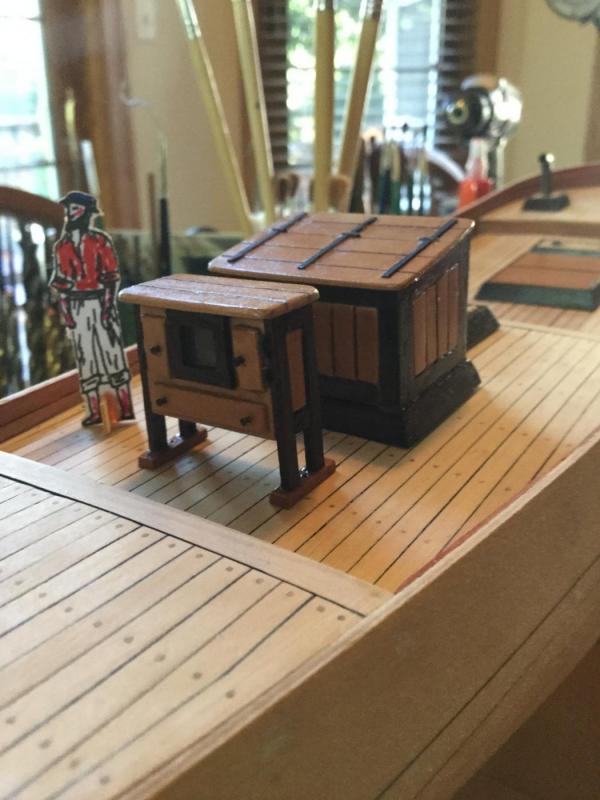
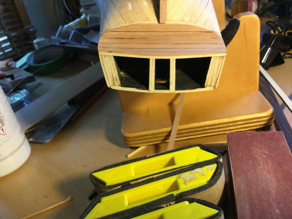
The binnacle, with my 5/16" = 1' scale sailor standing next to it.
- Elijah, KenW, zoly99sask and 8 others
-
 11
11
-
-
-
-
-
-
-
Nice job. With filler and sanding, a nice solid base for the second layer.
- Elijah, captgino and zoly99sask
-
3
-
I'm already impressed. I resawed my lumber to about 1/16"-3/32" on my bandsaw . A pass or two with the coarse paper, and a pass or two with the fine and I was good to go. I am also blown away by the accuracy of the ramp adjustment wheel. It's dead-on. A great tool!
- WackoWolf, zoly99sask, Elijah and 3 others
-
6
-
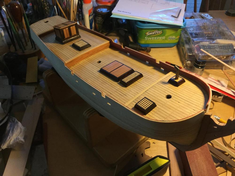
While waiting for my Byrnes thickness sander (which I used to mill the hull planking) I started on some of the deck furniture. I finished the hatches, and added one to lead the anchor lines below. I enlarged the companionway from the plan specs. I need to add iron ring pulls for the doors. The most important change was to fabricate a galley stack from brass. The plans actually call for a "smoke stack" made of walnut! Tha ship would have caught fire after serving the crew their first dinner aboard!
I still need to complete the binnacle, windlass, bits and ladders etc. The woods used are rosewood, boxwood and swiss pear.
-
-
Here's a link to my AVS log. I scratch-built a stove for the model. You can use whatever you like: text and/or photos.
- Canute, mtaylor and zoly99sask
-
3
-
-
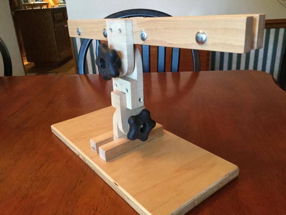
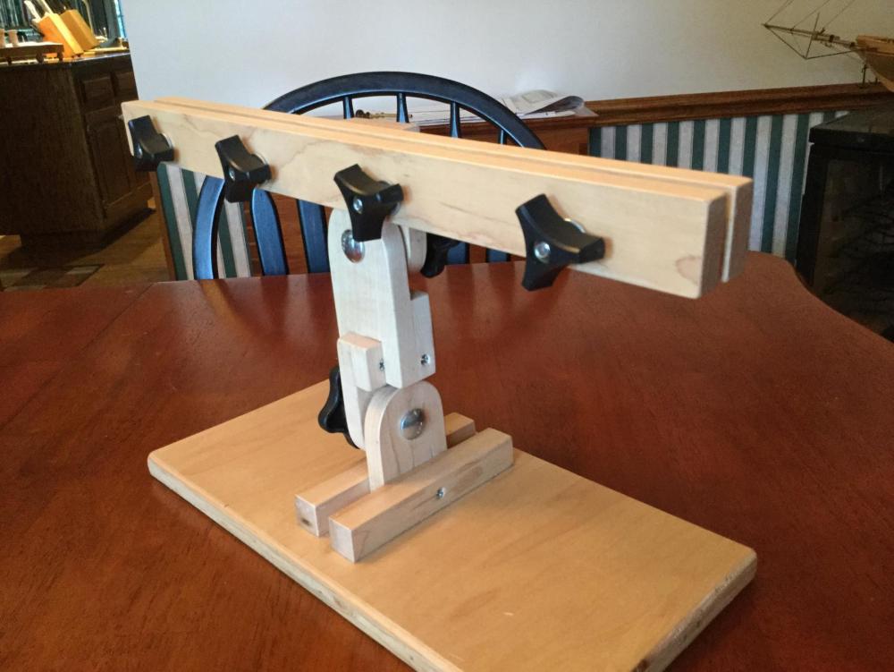
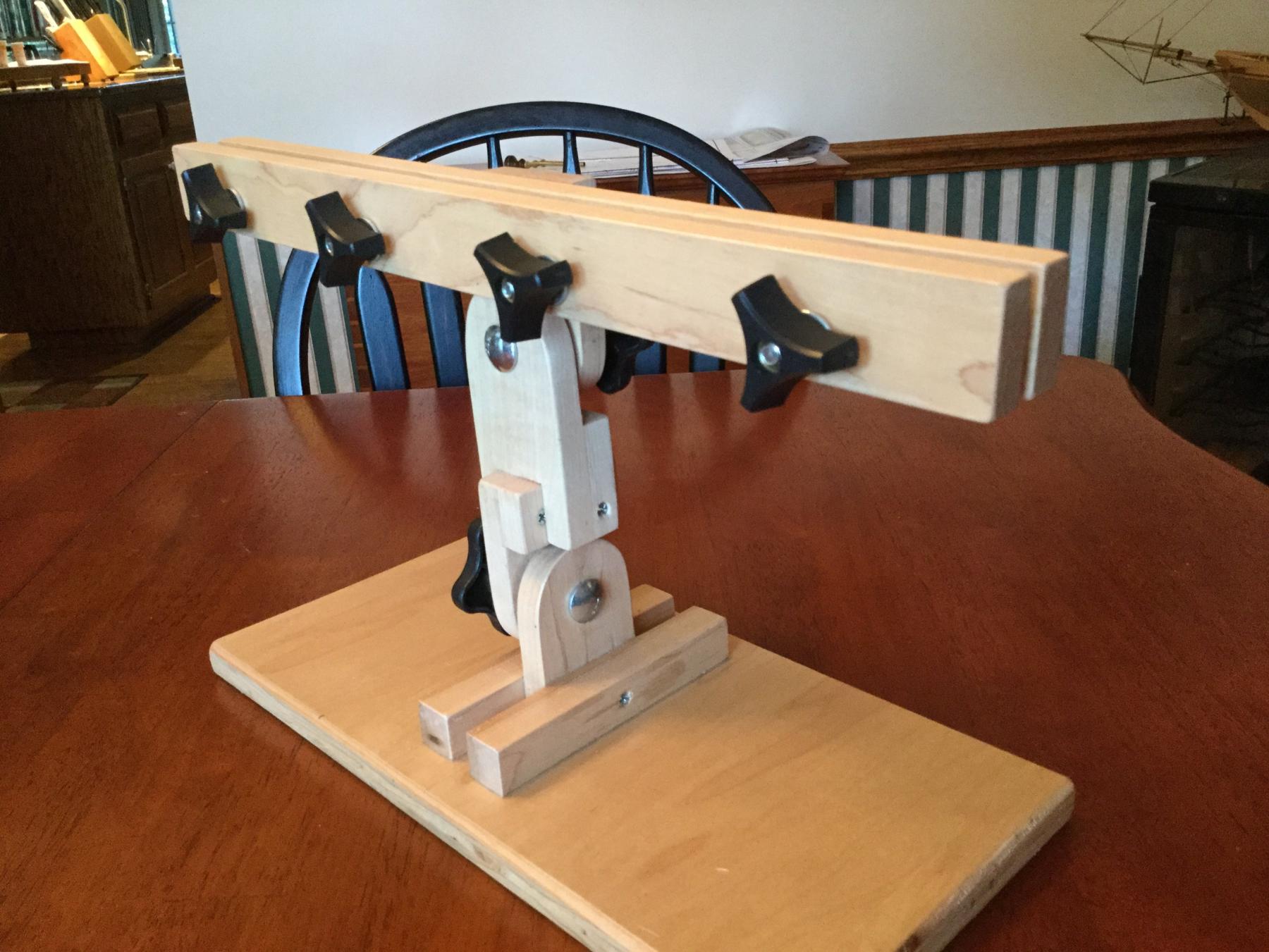
I assembled my keel clamp. The first task was to drill the holes for the carriage bolts which form the pivot points. They are 5/16", except for the keel clamp itself which has four 1/4" carriage bolts. The two knuckles that form the 2 axes of rotation were glued and screwed together, and the lower axis piece was glued and screwed to the base. All the parts were given 3 coats of water-based polyurethane. There are washers between adjacent wooden parts and where the through star nuts tighten down. I had most of the hardware on hand, but if you went to purchase it, it would be about $20 as I've built it. If you substitute plain old metal thumb screws, the hardware should be under $5!
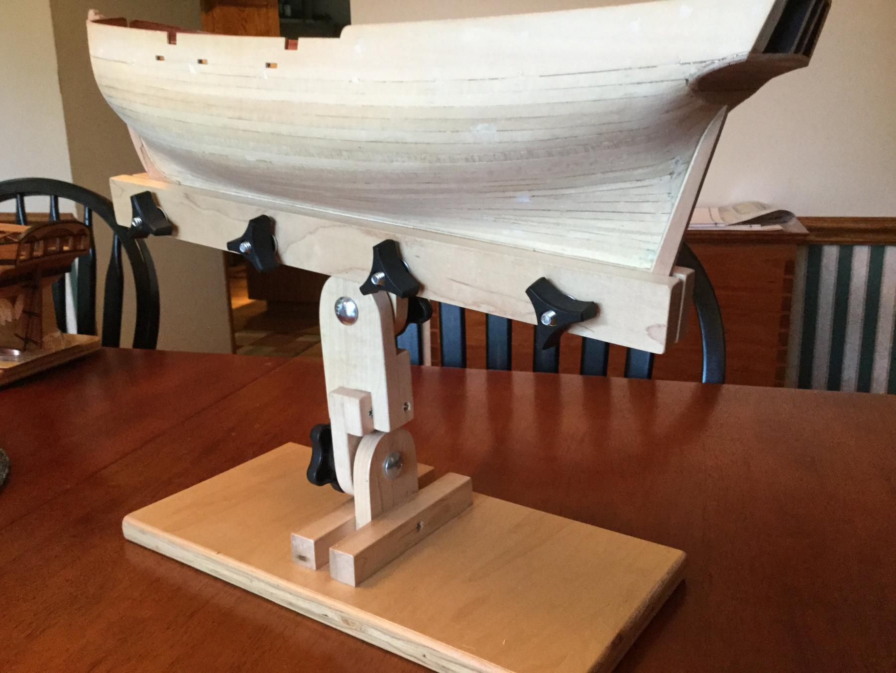
The clamp is very stable, even with a model in place due to the large base, but one might consider clamping it to the table top for safety. It is a little top-heavy!

-
Don: Beautiful job on the planking! I love the color of the hull. The variation in plank color only adds to the model. Well done!
- Seventynet, Eddie, Canute and 1 other
-
4
-
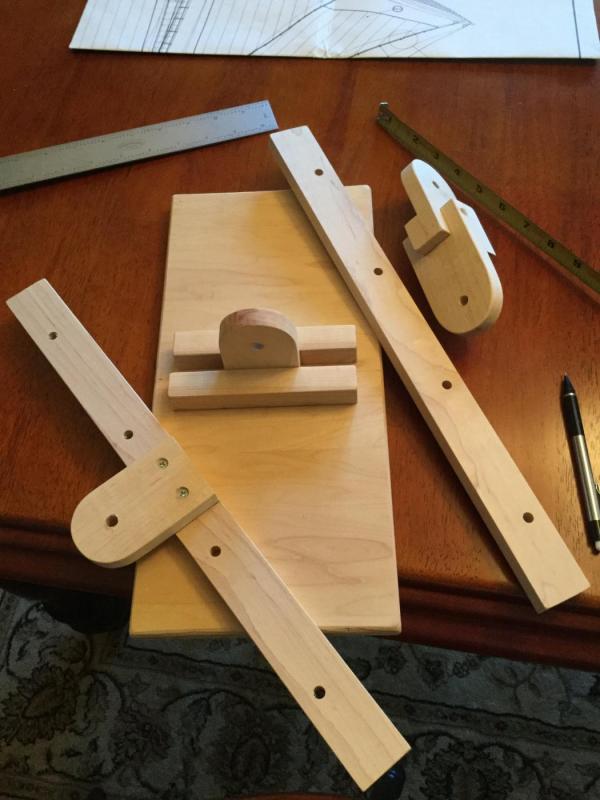
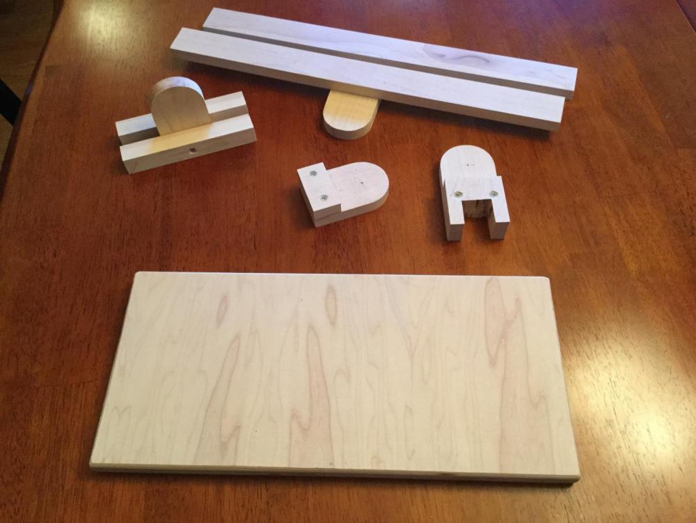
I'm getting ready to plank the hull. I need to establish the wales first, but before that I needed to plank the counter. I used 1/32" thick swiss pear, 7/32" wide. Because I need to establish a waterline for my "two-tone" planking of the hull, I decided I needed a keel clamp. Rather than buy one, I spent the afternoon today cutting out the parts out of some 1/2" hard maple I had on hand. I'll assemble it tomorrow. I have most of the hardware on hand, but you can build this for less than $5 if you have some 1/2' hardwood around. I'll post photos of the finished keel clamp tomorrow.
- zoly99sask, GuntherMT, mtaylor and 6 others
-
9
-
-
The planking is looking good so far!
- Elijah, captgino and zoly99sask
-
3
-
-
-
-


Making Fire buckets
in Metal Work, Soldering and Metal Fittings
Posted
Awesome job!