


Snug Harbor Johnny
-
Posts
1,501 -
Joined
-
Last visited
Content Type
Profiles
Forums
Gallery
Events
Everything posted by Snug Harbor Johnny
-
 Everything's looking ship shape! Well done !
 -
... SO many Springtime activities and other 'life gets in the way' stuff that I'm not getting much done in the shipyard right now. I thought I'd write a letter to my teenage self - not that he'll ever get to see it, but what the heck. Dear Young Johnny, You can do anything you sets your sights on if you believe in yourself ... except Calculus or advanced Physics - well, other really hard stuff that takes a near genius mind that can recall lots of facts/data easily. And forget excelling at things that require an athlete's body like gymnastics, high diving, ice skating or any professional sport - you'll hurt your body. You can practice piano many hours a day, but you're going to 'hit a wall' where you just won't get any better - so play keyboard to amuse yourself when no one can hear. Steer clear of trying to run your own business, running for public office or trying to 'change the world' - there is no Field Marshall's baton in your foot soldier's pack because you're an 'expendable', like all the other grunts. Focus on achievable things like safe driving, tending house plants, cooking pasta in the right amount, caring for your family ... stuff like that. Don't despair, for with time and some luck you will achieve competence in a limited number of ordinary, unremarkable things that you can do almost every day with repeatable results. You'll always be the 'star' of your own sitcom, but avoid speaking to the imaginary TV audience ... people will think you're strange. You can write that novel, but do it for your own satisfaction since no one will line up to read it. Save some money along the way - you're going to need it later. Yours truly, Old Johnny
-
sagging standing rigging
Snug Harbor Johnny replied to Dziadeczek's topic in Masting, rigging and sails
I'm betting that polyester thread is a good bet for making scale rope - don't forget that 'stretching-out' the rope is an important part of the process, just as it is for making full-size rope (which I've done for demos at historic sites). Cotton and silk can be subject to deterioration over time, as I've seen with a model ship my father made 70 years ago and now needs re-gigging (he used cotton). Flax is approved in the 'rules' for museum quality models, but flax thread fine enough is hard to find and costly. Although high quality polyester (Mettler or Guterman) has not passed the 'test of time' yet, I'm betting it will. -
Steven, I've been looking into the history of the HGaD (my acronym, to avoid confusing it with the Great Henry built by his father Henry the 7th in 1488 or the earlier Henry Grace), and the sources available have high concurrence that the re-build in 1536 lowered the stern castle (and possibly the fore castle) enough to lessen her tendency to heel (a bit top heavy?), thus reducing her tonnage burthen to around 1,000 ... AND added top gallants. So perhaps her former tonnage was something like 1,200. Now Henry the 8th may have built the HGaD (launched 1514, finished 1515) to counter the Scottish Great Michael, who's stats vary considerably depending on which source one looks at, and many estimate the tonnage at around 1,000, possibly more - a 'Carrack on steroids' and the largest built at the time. With an ego like Henry's (perhaps a megalomaniac), he had to outdo the Scots. The painting of the embarkation of Henry the 8th (for the Field of Cloth of Gold, an event that occurred in 1520 - although the painting had to have been done after the fact) is truly remarkable and in quality is comparable to the painting of the 1521 voyage of the marriage party depicting similar ships. Both commemorative paintings most likely were painted within a couple years of the events portrayed, given the importance of the events and the PR value of painting them. Neither work shows any top gallant sails, nor do any other depictions I've seen dated before or no later than the 1520s. So if one were to attempt a model of the tipsy HGaD "pre 1536", might that have (apart from an extra deck on the castles) only yards for main sails and top sails (plus lateens on the 2 masts astern)? I note that in both of the above-mentioned paintings, there are shields around the tops of the castles. This would be a practical feature to protect archers or hand gunners on the top decks from anti-personnel fire of various types from opposing ships. Any thoughts on this? Johnny
- 740 replies
-
- 4
-

-
- Tudor
- restoration
- (and 4 more)
-
What look like 'gun ports' on clipper ships function as 'water doors'. Clippers navigating rough seas (like around the Horn) had big waves crash over the gunwale and onto the desk. Scuppers alone would not drain such huge quantities fast enough, but the weight of the water would push open the water doors and drain out. The weight of the doors (after drainage) would shut them again, and any wave hitting the side of the ship would only push the door against it's recess - thus keeping water out ... it was a 'one-way' system. This is a detail that can either be left out, or perhaps simulated by gluing thin veneer squares at the places where the doors were, then painting over black.
- 47 replies
-
- 3
-
-
- Cutty Sark
- Artesania Latina
- (and 1 more)
-
You chose a great scale for the CS ... not as "small" as in 1:96 (but even so the 1:96 is a decent size for a ship model of CS - what, something like 34" stem to stern?), but not as large as 1:70 or 1:75 kit ( about 46"?). 1:84 should be 'in between' at about 40", and a little easier to deal with some of the small details. Using blocks and such slightly larger than 'strict' scale will still look OK.
- 47 replies
-
- 3
-
-
- Cutty Sark
- Artesania Latina
- (and 1 more)
-
A couple things I've observed on the Revell CS - the larger spars have (imitation) sheave openings at the ends where you can pass sheet chain through. Some have replaced wood yard for plastic and made tiny metal sheave units mounted to the front side of the yard end - which is fine, but at 1:96 I'm thinking of using at least the thicker molded yards as provided and still use the 'in the yard' sheaves, as such a method was not uncommon. (Since the Thermie was sunk, no one knows the rigging details of her - so when I get around to building there is more leeway to use various documented rigging options.) At the foot of the masts of the Cutty, there is a 'crown-like' collar of eyes that blocks for hauling sheets hook onto - and making them seems challenging at 1:96 (don't know how one would attempt it for 1:168 per Hackney). I'm of a mind to just install deck eyes around the masts for the same purpose, and pre-install blocks as mentioned in my previous post. Another MSW member suggest installing standing rigging from the mizzen mast forward (instead of front to back), and there is always Rob's technique (and others have also done so) of having mast sockets in a piece of wood so that test fitting and dry assembly of the masts can be done off the model - then placed (whether glued or not) into the sockets on the model. Hmmmm, come to think about it - perhaps one could consider not 'gluing' the masts at deck level (since they appear to be 'positively located' as molded). Once the standing rigging for the first level is in place, the masts won't be able to come out ... yet there still is the practicality of being able to remove them for repair, rework or modification. (You never know.) Having 'reversibility' can be a real advantage in a pinch. And once the plastic is "welded" by glue, going back becomes a virtual impossibility.
- 248 replies
-
- 1
-
-
- Cutty Sark
- Revell
- (and 2 more)
-
The assembly order of certain details take some thought beforehand. For instance, having perused (and I'll have to do a lot more of it) the Hackney book - there are some halyards that end in a double block going to one side or another near belaying pins for the associated mast. There is a corresponding double block below, whose becket is held by a deck eye below the pin rack. A line from the becket on the lower end of the halyard block is sheaved through the deck block, back to the halyard block - then down and back for a second sheave before going to the assigned belaying pin. I occurs to me that said deck block would be best installed on the deck even before the deck is cemented in place, as getting one's fingers or tools into tight spaces can be a pain. The blocks on the original are 'internally stropped', which is why some have used the plastic ones in the kit (even though out of scale). The fully scale blocks form HIS seem a little 'too small' for my skills, so I'll probably compromise with something 'in between' out of wood and strop them with line. The deck block could be tied to the intended deck eye, and I'll use a commercially available one (one source is the parts department of Model Expo ... their new catalog has NO Black Pearl or pirated kits that I can see), or just make what I need and put the end of the deck eye clear through a small hole drilled in the deck so the end can be bent and epoxied underneath. The halyard block can be laced to the deck block (again, before deck installation - and this goes for several such block arrangements extant on the CS) with extra line temporarily wrapped around the lines running between the two blocks. Much later, when the masting and sparring are being assembled as they would when building an actual ship, the end of the respective halyard can be put (stropped) around said halyard block - the method I use is to tie a small 'hangman's noose, then pull tight, cement and trim. The final adjustment would them be made on the sheaving line already between the two blocks - which is then belayed, with a 'fake' coil places over the respective pin. 'Seems like a lot of thought to go into this particular detail, but it will make the rigging process less frustrating in the long run - having pre-thought out every move ahead of time instead of just 'winging it' as I go along. I note that there are also blocks mounted on the pin rail itself in places. Every line has a purpose, so I have to learn them all. This is why (after much pondering) I'm eschewing sails altogether ... they 'hide' a lot of the model anyway. Without sails, bunt lines can either be 'stopped' by a stop knot at the bunt blocks - or omitted entirely. Underhill shows how a luff line can be combined with the outer bunt line (bunt bent to leech p.169, fig.151 ... IF one wants to include sails) and two bunt lines can be rigged so that they are controlled by a SINGLE resultant line whether sails are included or not (p.163, fig.150) that goes down to a belaying pin at deck level ... a compromise that will reduce the 'spaghetti' effect of all separate lines while maintaining authenticity. Yup, more advance study and planning.
- 248 replies
-
- 1
-
-
- Cutty Sark
- Revell
- (and 2 more)
-
Masts are sections of tree trunk, of course - so the growth rings (harder than the early season wood in between) encircle throughout. Take a look at the 'end view' (or a stump) of a newly felled tree and you'll see what I'm talking about. a living tree has an awful lot of water content, and much of this is lost once cut as it dries ... but there is always a water content (unless left in the desert, and even then there is a little). Wood shrinks width-wise as it dries, so the further out in circumference the greater chance of a serious crack developing - which will run up and down. Oiling dried wood helps lessen the travel of moisture in or out of wood in the short term - furniture makers know all about this. Strong forces can bend and snap a mast, and if you simulate this by snapping a branch often large 'shivers' connected to one piece or another can be produced. Wrapping rope around in bands will significantly reinforce the mast section against snapping. Perhaps you've seen period cannon with iron or steel 'bands' around the barrel ... they also do reinforcing.
-
'Seems for once I'm 'first in line' ... so contact me by e-mail per the info in my private message. Fair sailing, Johnny
-
I've just re-read your entire log, and find it to be highly instructive ... I'm still mulling over how to deal with the Revell 1:96 Thermie kit - that is with modifications to make the deck layout closer to the original (once I've finished my present project). Everything about building the hull, painting, etc. is food for thought. I recommend leaving the log on MSW as a benefit to those with an eye on building these kits. Hull building is one phase ... and the rigging of a ship appears to be a whole different trip - perhaps more demanding than building the hull in phase one. I'm half dreading and half anticipating the challenge when I get to phase 2 of my build. Edison said, "Invention is 1 percent inspiration and 99 percent perspiration". Yogi Berra said, "Baseball is 90 percent mental ... the other half is physical". I suppose both may apply to ship modeling.
- 248 replies
-
- 1
-
-
- Cutty Sark
- Revell
- (and 2 more)
-
I find myself constantly repairing one snafu or another. Patience and persistence can go a long way in this hobby ... as well as imagination. Then there was a time (as a teen) when my all-wood Cutty Sark (can't remember if it was from Sterling or a Scientific kit)that happened not to be in a case received a direct hit from my kid cousin's shoe that he'd thrown across the room with great force (trying to hit my sibling). The damage done by the shoe was further increased by the model's 6 foot fall to the floor. Of course I was stunned and dismayed, but did I recon the ship a total loss? ... well ... yes, regrettably - and the teenage 'me' just didn't have the heart to try and rebuild all the masting and rigging (the adult 'me' would have). Incidentally, that cousin did so much damage around the house - such as ruining my father's 'war trophies' of an Orisaka rifle and a Japanese Naval Officer's sword (with a samurai blade) ... as well as attempting to burn our house down, that his parents were told in no uncertain terms that the bad boy would never again be allowed to visit (perhaps at least until he'd 'grow up' quite a bit). Hmmmm, parents tend to defend their offspring 'no matter what' they've done - so none of them ever visited again. I plan to make cases with acrylic panels (glass is heavy and can break) for things I'm working on these days that won't fit into a hutch with glass framed doors.
- 218 replies
-
- 1
-
-
- Victory
- Caldercraft
- (and 1 more)
-
BTW mate, try to salvage stuff for use elsewhere ... like those nice 3D brass stanchions !
- 248 replies
-
- 1
-
-
- Cutty Sark
- Revell
- (and 2 more)
-
I don't think anyone's suggested "Dust Off" ... compressed air in a can. Some have plastic tubes (like WD 40) to direct small shots of air into crevices. Have a couple cans handy, because as one is used the can gets COLD and the pressure drops ... something to do with thermodynamics. BTW, outside is best to do this on a mild day - or perhaps in an open garage. Suggestion #2 would be to use an air brush w/o paint ... just the air. Or #3 the nozzle from any air compressor. Getting the 'lion's share' of dust and debris off before using brush or Q-tip may assist in the process.
-
"Much of the satisfying work of life begins as an experiment, and no experiment is ever quite a failure." Alice Walker 1944 -
- 248 replies
-
- 1
-
-
- Cutty Sark
- Revell
- (and 2 more)
-
'Super job, mate ! I love the old 'battleship grey' ... for a while now it's been Hayes Grey underway. The figures bring the ship 'to life' and add a lot to the impression. 'Don't know if I could have managed the fine PE as well as you have.
-
I made a 'fairing tool' by taking a hacksaw blade, grinding off the kerf of the teeth (and dulling the teeth as well), then using contact adhesive to glue sandpaper to both sides of the blade. The blade can be gently 'flexed' to get it to deform into a curve, and then can be rubbed against bulkheads, planking (whatever) to get a nice even and gradual curved shaping.
- 50 replies
-
- 4
-
-
- vasa
- deagostini
- (and 1 more)
-
Are these lifts correct?
Snug Harbor Johnny replied to Louie da fly's topic in Masting, rigging and sails
Steven, 'Looks to me like the 'block' at the yard ends are similar to a 'violin' block. There is a single lower sheave and a single upper sheave. As the yard is raised, the angle of the lift changes - so the lower sheave permits a single rope with both ends fastened to the yard to automatically re-adjust so the tension remains even. A line starts at the top end of the block shown (method of attachment not detailed, but could be a becket), goes up to the first sheave of a double block below the top (out of the picture), comes down and passes through the single upper sheave of the yardarm 'violin', back up to the second sheave of the double block under the top, then down to a rail (or other attachment point) at deck level. -
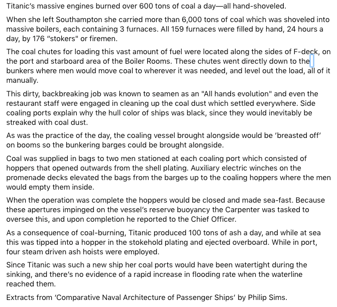
Ahoy! 'Came across this item of interest on how the Titanic (and other contemporary vessels) were fueled (coaled). In spite of significant technological developments, this old-school, grimy and laborious job of hand loading thousands of tons of coal still had to be done. Once fed down the exterior chutes, the coal had to be distributed, then hand stoked 24 hours a day into the massive furnaces ... and the constantly produced ash had to be disposed of. 'Must have been a hot and grueling job down below, and their grog at shifts end was well earned.
-
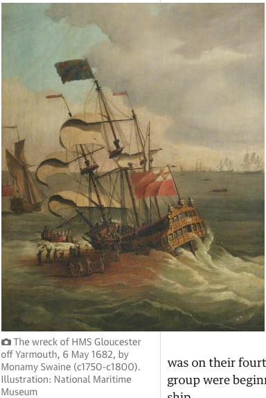
I was perusing 17th century warships and came across the wreck of the HMS Glouster (built 1652, wrecked 1682) recently located and now a protected site. A painting shows the same course plus topsail configuration I was talking about.
- 2,699 replies
-
- 5
-
-
- heller
- soleil royal
- (and 9 more)
-
The 'original' (1960s) Billings Vasa (their label - Wasa) had one bulkhead a bit too "fat", and I didn't appreciate the need for fairing it 'presuming' that it was that way on purpose. Rule 1 - Never 'assume' anything about a kits contents or instructions. Adding material to a bulkhead that doesn't come out far enough should be done as early as practical. I know about thin bulkhead pieces braking off at deck level, mostly because there is often just a central ply with a veneer on each face. This makes the grain of the core the predominant grain subject to whatever weak direction it has. There are hobby plywood made up of multiple layers that are better, as well as making up one's own 'plywood' of whatever species veneer available - then transferring the outlines using the stop bulkheads as patterns. Strategy #2 is to cut out those spindly projections (leaving a notch in the side of the main part of the bulkhead), and gluing a solid piece of wood with favorable grain as a replacement. The more advance precautions made early, the fewer problems later on.
- 50 replies
-
- 1
-
-
- vasa
- deagostini
- (and 1 more)
-
'Love that 1692 RL drawing showing just main and topsails on the fore and main masts. The flagstaffs above the topsails are short and spindly enough that they could (if they ever were so fitted) only handle the puniest of top gallants (which I doubt). I saw a representation of the 1628 Vasa (aka Wasa) similarly rigged, which gives me a reason to try and finish the one I'm working on in that manner. Given that Vasa was krank from the outset (perhaps the reason that a forecastle deck was not installed due the weight it would have added with ordinance), the 1692 RL configuration seems more likely.
- 2,699 replies
-
- 2
-
-
- heller
- soleil royal
- (and 9 more)
-
Your progress is impressive ... This is bound to come out well.
-
Over time, ordinary batteries can leak and make a mess ... unless there is easy access and they are changed annually. CR2032 round lithium batteries may be a better option.
