
HOLIDAY DONATION DRIVE - SUPPORT MSW - DO YOUR PART TO KEEP THIS GREAT FORUM GOING! (Only 13 donations so far - C'mon guys!)
×


Snug Harbor Johnny
-
Posts
1,456 -
Joined
-
Last visited
Content Type
Profiles
Forums
Gallery
Events
Everything posted by Snug Harbor Johnny
-
 Your post has a fascinating 'quick-build' video of AL's San Francisco. There is a similar AL kit named San Juan, and the video would be just as helpful for that. Either could be built into a Golden Hind (ex Pelican) with a few modifications: omitting the lower gun deck and the vertical wood strips on the sides; possibly razing (as in race-built) or reducing the highest stern deck; omitting the 'Captain's walk' (neither contemporary drawing of Drake's Caribbean fleet show any exterior 'walks', nor the 3-D miniature GH atop the 'Drake cup' presented to him by the Queen); and mounting 2 guns somewhere forward - either on the forecastle deck or perhaps at 45 degrees on the weather deck under the forecastle where the planking curves significantly. Portuguese navigator da Silva had a lot to say about the GH (and Drake as well) as he had the run of the ship (likely advising Drake, the first English captain to venture into South American waters) until Drake 'dumped' da Silva on the west coast of Mexico (likely being thought of no further use and therefore a liability). Translations of daSilva's deposition to both the Spanish authorities (who may have hoped to find any weakness or inconsistency in his story, so he could be accused of collaboration) AND the Spanish Inquisition ... so his soul might have been in as much trouble as his body had he not held up under close questioning with accurate and consistent testimony. Good reading there.
- 1 reply
-
- 1
-

-
- San Francisco
- Artesania Latina
- (and 1 more)
-
Well done, Simon. The copy I bought off Amazon is from 1969. The dust jacket is taped (no big deal since I'm not a book collector - and the content is where the value for a modeler is), and the exterior cloth of the book is green.
-
If there are photos of details/techniques that I want to save for future reference, I'll just use a partial screen capture option (differs by computer type and system) to 'grab' the area of interest and it appears on my desktop as a 'screen shot' - which is dragged into the applicable sub folder in my photo file.
-
Looking for correctly scaled lines and rope
Snug Harbor Johnny replied to Michael Smith's topic in Masting, rigging and sails
Chuck also sells the "Rope Rocket" in easy-to-build kit form. That plus an electric drill, and you can make just about any type, scale and color rope you need ... for this and any future project. EDIT: oops, 'didn't figure the small scale of the present concern - so 'spun' rope that will be the correct size may not be available or able to be made on a rope making jig. Fine silk thread may work for the smallest. Specialty sewing stores or quilt shops sometimes have the finest size commercially available, and the weights go up from there. -
'Sounds like they have some slow-moving inventory of a kit that they want to sell at cost BEFORE the end of the year for tax purposes. If they made a buy of new stock (from, um, 'various' sources as mentioned elsewhere on the Forum) - or if sales are less than anticipated recently - their inventory value may have increased. An increase in the value of year-end inventory when compared to the previous year will have a negative effect tax-wise. The increase in inventory value will have to be subtracted from business expenses - ergo subject to taxation - per IRS and State regulations, since those finished goods have not yet been sold. That is to prevent a business from piling-up a bunch of inventory so they can deduct the cost of it from taxable sales (to artificially lower the tax bill).
-
You're right about clippers having armament for insurance purposes ... but that requirement was dropped at some point due to the speed of clippers and increasing safety in the vicinity of Hong Kong. 'Don't know when that was BUT, the Thermopylae built in 1868 had 2 cannon (and other weapons) - a the definitive model built by Cyril Homes (1900 - 1984). This second model he built of the Thermie was started in 1935 and finished in 1979, and bought by the Museum of Applied Arts & Sciences (MAAS), Sydney, Australia in 1980 and is on display and images are available on the internet. Humes was able to interview crewmen who had served aboard Thermopylae to gain the best information on her configuration. The coastline south of Hong Kong was often the location of pirate attacks from junks. Cyril said that "Thermopylae" was well prepared with two small guns lashed to the main deck and various other weapons including 20 Tower Hill muskets, 20 cutlasses, 20 boarding pikes, 20 round shot and 20 grape shot located around the mizzenmast below deck. Since the Staghound was lost PRIOR to the launching of Thermopylae, the requirement for cannon would have applied. EDIT: The other model is in the Melbourne Museum - images also available - and BOTH models are done very well. Some of the images available on line in 'out of the case' and some are inside a display case. Another model is in the Greenwich Museum ('guess in England). The wreck you mentioned might just be the Staghound ... and there might be means of determining the identity - short of finding the figurehead.
-
I've been thinking about a clipper for a long time, but first wanted to try and educate myself about nautical terms and all the building practices that can be found on MSW if one looks around a bit and watches the builds in progress. Now complex rigging seem a bit daunting - not just learning about the ropes, what they do and the blocks involved, but the care and skill needed to accomplish (and difficulty is influenced by the scale chosen) with eyes and eye-hand coordination that is not as good as it used to be. And it seems that rigging a model is easily half the work of the entire project. From a learning standpoint, I love the Forum for the wealth of information available (if one looks) and indeed have made some progress useful in multiple time periods. Given that ships had to address practical aspects of sea navigation and ever changing weather conditions, there is a logic and purpose to everything as the art evolved. Halyards, lifts, braces, bunt and leech lines, reef tackle out-haul, in-haul, etc. all start to make sense when one imagines actually working the ropes on a real ship. I have also acquired some useful books mentioned here and there on the Forum. My decision on the Vasa (Wasa on the suspended log) is to get it to a point representing construction where the first mast sections are in place with shrouds/ratlines, and try to get the decorations acceptable (even with short cuts & simplifications) however I'm able to do it. The original ship in Stockholm has only the first mast sections. The first edition (ca. 1970) Billings kit got a lot wrong, and many corrections have been cobbled to date on my project. All the decoration at 1:100 must be scratch - another challenge. Its been an on&off thing for a long time. The clipper I've thought about is the Thermopylae, and I was able to come by a complete Revell kit for $60 (an early version from the crispness of the parts and the age of the crumbling box) ... yet we all know the shortcomings due to cloning the CS kit by the manufacturer - as well as fragility/springyness of the masts, spars, whiskers and martingale. Soooo, there would have to be some bashing to get close enough to what is seen on the Hume model of the big T. That will negate some of the advantage in not having to build a hull from scratch via commonly used means - yet I won't have to worry about manually applying metal plates or copper tape. Studying the CS build by Bruma, ands also several builds by Rob R. (not just the Glory of the Seas) show a lot of useful improvements that can be done, including using wood for sturdier masting/sparring. Popeye the Saillor's build of the Sergal Thermie showed the challenges of working in too small a scale - as well as challenges with that particular kit. One must also deal with sheer model size if a large ship is done at 1:72. At present I have a final big winter task of installing hardwood flooring in our family room (the LR & DR already done before Christmas). After that what I'll probably do is work on BOTH the Wasa and the Thermopylae concurrently - each on a different build table in what the Admiral considers my 'man cave', that is partitioned off on one side of the basement (since a pal will occasionally visit, its more like a bud hole). Whatever I want to work on (time permitting as there are always seasonal chores and per-diem work at a hospital as a Pharmacy Tech), whether in wood or plastic with wood enhancements, I'll just hack-away with. I have the H.I.S. Model Thermie laser-imprinted decking (to cover the annoying deck joins of the plastic parts that will become a false-deck - as well as not having to imitate wood with paint ... a PITA), a set of wooden blocks/deadeyes plus resources from parts-kits that will never be built - so maybe I can do a fair job of it as a first go. Rob's technique of having furled sails atop the yards will eliminate the need to bother with jackstays - although doing a few for yards w/o a furled sail may be a sleight-of-hand that suggests the same details are on the covered yards. Whatever works. Fair sailing ! Johny
- 602 replies
-
- 1
-
-
- Flying Fish
- Model Shipways
- (and 2 more)
-
Once again, these are extremely helpful photos.
-
Ahoy, George ... a VERY nice build you have there. I'm noting all kinds of details to learn about before starting a clipper build, and the mizzen forward advice seems practical.
-
USS Texas (BB-35) - in drydock
Snug Harbor Johnny replied to Kevin's topic in Nautical/Naval History
Funny thing about photos ... it seems there's no shortage of people who like to slap a "copyright" on anything they can get their hands on - whether or not others have done so for the same old photo ! The idea is, their own copy (or print) - say, of an old postcard from early in the 20th century - has 'unique identifiers' such as postmarks, notes, folds, tears, spots, foxing ... whatever. And they want to claim exclusive 'rights' to the image that happens to be in their possession. Once an item is in the public domain, its there permanently. Old books containing illustrations (we're talking over 76 years) have become public domain under laws then in effect. Now the revised laws effectively allow stuff published or in print since the revision to get (effectively) permanent protection from commercial use due to the intricacies of the legislation - designed to permanently protect, say, Disney material - which are also registered trademarks. But the old postcards mentioned above weren't issued with copyrights at all, since they were sold as ephemera (often printed abroad) - ergo became public domain from the time they were sold. Of course, these days someone can take any old picture and apply "filters" and effects to make whatever changes they want and then copyright it as new. Its all very confusing. However, anything one can see on screen over the internet can be 'captured' (various operating systems have various names for duplicating the pixels within a 'box' you drag over the screen - such as 'grab it') for personal use under 'fair use'. And a forum such as ours can equally fall under the fair-use allowance, since we're not charging, branding or making claims other than 'hey, I saw this on the internet'. Speaking of something I saw on the internet, I'm posting a juxtaposition of photos below. Using screen shots is better than relying on 'links' that can later go haywire.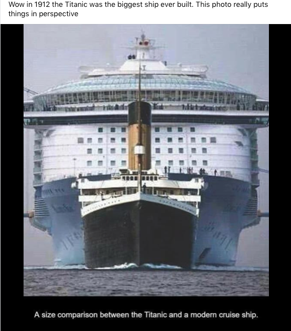
-
Cleaning needle files
Snug Harbor Johnny replied to MarcM's topic in Modeling tools and Workshop Equipment
If all else fails, buy some more mini-files. I think it was Gertrude Stein who said, "The easiest way to change a typewriter ribbon is to buy a new typewriter." -
USS Texas (BB-35) - in drydock
Snug Harbor Johnny replied to Kevin's topic in Nautical/Naval History
How about this 'build' (incomplete, as many of ours are ...)
-
National Geographic's "History" magazine just came out, and includes an interesting article on Greek triremes.
-
USS Texas (BB-35) - in drydock
Snug Harbor Johnny replied to Kevin's topic in Nautical/Naval History
'Guess "links" sometimes go off into Neverland. A safe way to post an image is to take a 'screen shot' of it (a form of WISIWIG that merely duplicates pixels), then drag the image onto a post. -
A popular degreaser until about 20 years ago was 1,1,1 trichloroethylene (aka 'Tri-chlor'), and there were open bins of it all around one factory I used to work for. You could buy it in cans at the local hardware store as well. Due to various toxicities (as well as VOC concerns), it has been replaced with something else. (For how long?) Also, I remember lead (or tin-lead) tinsel for Christmas Trees. We'd all play with the stuff, but never ate any.
-
'Brings to mind an old yarn ... There once was a man from Nantucket, Who kept all of his cash in a bucket, But his daughter, named Nan, Ran away with a man, And as for the bucket, Nan tuck it. Then he followed the pair to Pawtucket, The guy and the girl with the bucket, And he said to the man, He was welcome to Nan, But as for the bucket, Paw tuck it. "Nantucket" - It rhymes in our head, With something that shouldn't be said, Around mothers and Vicars, And those with weak tickers, (Unless you've invaded their bed !) 😉 What arrrrrrr ya doing?
-
'Just saw a post of a Norske Love build that has the 'transitional' tuck we've been pondering. Picture below:
-
USS Texas (BB-35) - in drydock
Snug Harbor Johnny replied to Kevin's topic in Nautical/Naval History
The pictures in the previous posts seem to have 'vanished', but i just found something of interest to throw in ... By early 1942, it was determined that Oklahoma could be salvaged and that she was a navigational hazard, having rolled into the harbor's navigational channel. Preparations for righting the overturned hull took under eight months to complete. Air was pumped into interior chambers and improvised airlocks built into the ship, forcing 20,000 tonnes (19,684 long tons; 22,046 short tons) of water out of the ship through the torpedo holes. Twenty-one derricks were attached to the upturned hull; each carried high-tensile steel cables that were connected to hydraulic winching machines ashore. On 28 December, Oklahoma was towed into drydock No. 2, at the Pearl Harbor Naval Shipyard. Once in the dock, her main guns, machinery, remaining ammunition, and stores were removed. The severest structural damage on the hull was also repaired to make the ship watertight. US Navy deemed her too old and too heavily damaged to be returned to service. Disaster struck on 17 May, when the ships entered a storm more than 500 miles (800 km) from Hawaii. The tug Hercules put her searchlight on the former battleship, revealing that she had begun listing heavily. had begun to sink straight down, causing water to swamp the sterns of both tugs. As the battleship sank rapidly, the line from Monarch quickly played out, releasing the tug. However, Hercules' cables did not release until the last possible moment, leaving her tossing and pitching above the grave of the sunken Oklahoma. The battleship's exact location is unknown.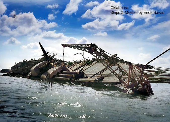
-
True enough, Steven ... I forgot how SHORT some of those doublets got ... plenty of ventilation for the (uh) 'bits', and the historic precedence for the micro-skirt. Now your model of Henry VIII's flagship fits right into the 'padded codpiece' era - and Henry liked to boast of his prowess.
-
Thats German for 'excellent' .
-
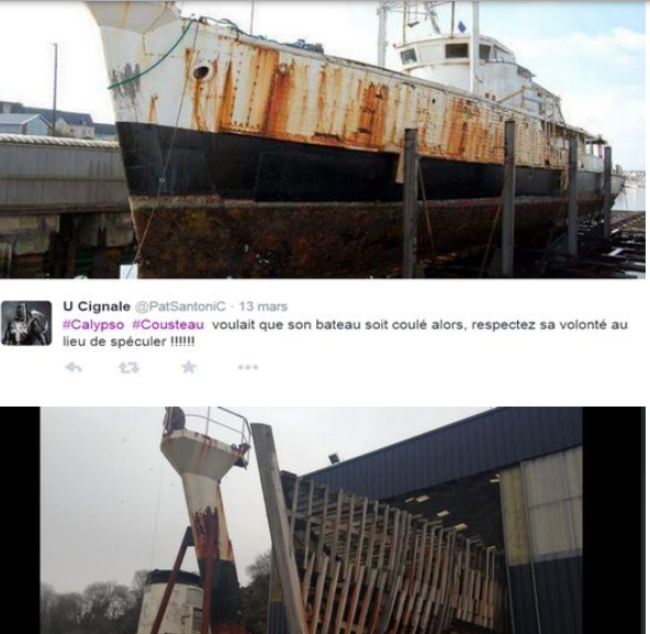
After poking around I found two images (one above the other) that appear to show that wooden framing was 'skinned' in steel (by the looks of the rusting patterns) ... perhaps this is why the Billings kit has a plastic hull - after all, the metal was painted and there would be no plank or grain marks. There seem to be slight bumps where fasteners of some type attach the metal skin to the internal ribs. Check out the available build on MSW, and builders seem to use the material provided (with all sorts of enhancements for equipment on deck, etc.).
-
Ausgescheishnett
-
Don't for get the codpiece ! 😉
-
There was a brand with red tinted glass called 'Red Head' extinguishers - and one old factory I worked for had a few upstairs.


