Snug Harbor Johnny
-
Posts
1,500 -
Joined
-
Last visited
Content Type
Profiles
Forums
Gallery
Events
Everything posted by Snug Harbor Johnny
-
 Wintergreen is right about the 'early days' once the Vasa was raised. I read with interest the National Geographic article (when it came out ... 'showing my age') and the pictures of the hull again in daylight showed that the entire stern had been ripped apart from early 'salvage' efforts - mostly to get the cannon back then, as well as the bow and the decking was gone. So until a 10 year program of stabilization could be complete - and also finding all the broken bits on the sea bottom and preserving them as well - it was anyone's guess as to what the missing portions might have looked like ... perhaps a little like guessing what the Golden Hind looked like, but there was a lot more to go on with the Vasa, and even the Mary Rose. Hmmm, I still think that with modern techniques the British might yet be able to unearth the hull remnants of the GH - thereby at least getting the length, beam, tonnage and lines below the waterline. I'm amazed at how the Swedes have put all the pieces of the 'giant jigsaw puzzle' back together. If I ever win a Nobel Prize (which includes a free trip to Stockholm), a trip to the Vasa museum will definitely be in order ... also with a decent smorgasbord and sauna. Therefore, I do not fault Billings much - and can highly recommend their current Vasa kit. Yes, the carvings are molded plastic, but the detailing is excellent - and plastic can be heated carefully to form as needed before mounting. The Corel kit has metal figures, and I don't think they have near the detail of the ones Billings provides. I compare two other Billings kits - the old Vikingskibbe (1:20), based on Skudelev 5 and the relatively recent Roar Ede (1:25) of the same boat. The old kit was inherited and by examining the materials provided (and a MSW build of the same), the old version is a real challenge. All the parts have to be cut out, the veneers are somewhat fragile and prone to splitting - yet the construction of the bow and stern are done as the original was - built up in successive layers. The new kit, which I have in stash has been adjusted in scale to go with their Oseberg kit (also 1:25 - a kit that has been improved in later releases and also in my stash), is laser cut thin plywood (a real time saver there and the strakes can either be stained OR bonded (before building) with walnut or mahogany veneer (as I intend to do). The new kit does not have the built-up bow and stern, but I saved the parts sheets from the old kit, perhaps to reduce the outlines to 1:25 and attempt to "meld" with the new kit built from contiguous planks. In another post somewhere I compared/contrasted the Scientific Robert E. Lee steamboat wooden kit with the plastic Lindbergh/Pyro kit that turns out to be the SAME scale. Obviously starting with a nice basswood hull is much preferable to a hollow plastic one, and the mahogany stand in the Scientific kit is a nice touch. Still, there are components in the plastic kit that can save time and add detail, such as the boiler and also to have full paddlewheels that spin on an axle (instead of cast metal partial wheel segments). The solid wood stacks are preferable, but the stack top trim (and much other trim) in the plastic kit will be the ones I'll use. Now in the case of the Endurance kit (under $200), just upgrading to brass stanchions and railings would add $60 to the kit price, as more ship-specific fittings would do. Costs associated with greater development time would also have to amortized into the kit price, as would better sails, rope and belaying pins. And OcCre has to consider the kit cost spread offered by their competitors. 'Hard to second guess this, so I can see the logic in selling an adequate kit that can be built 'out of the box' at one skill/experience level - yet still be enhanced by a builder at a higher level willing to make or buy any needed items. Whether I will get to all of the 12 kits accumulated thus far (and I've heard of stashes in the many dozens) before I head out to sea doesn't bother me. If I don't build 'em, someone else will get a chance.
 -
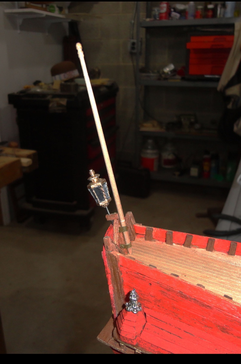
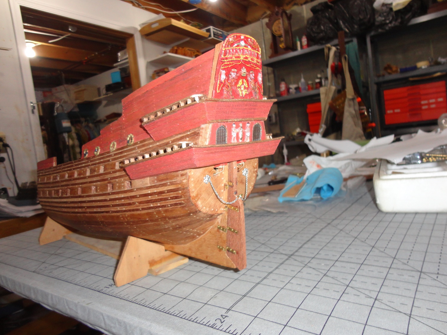
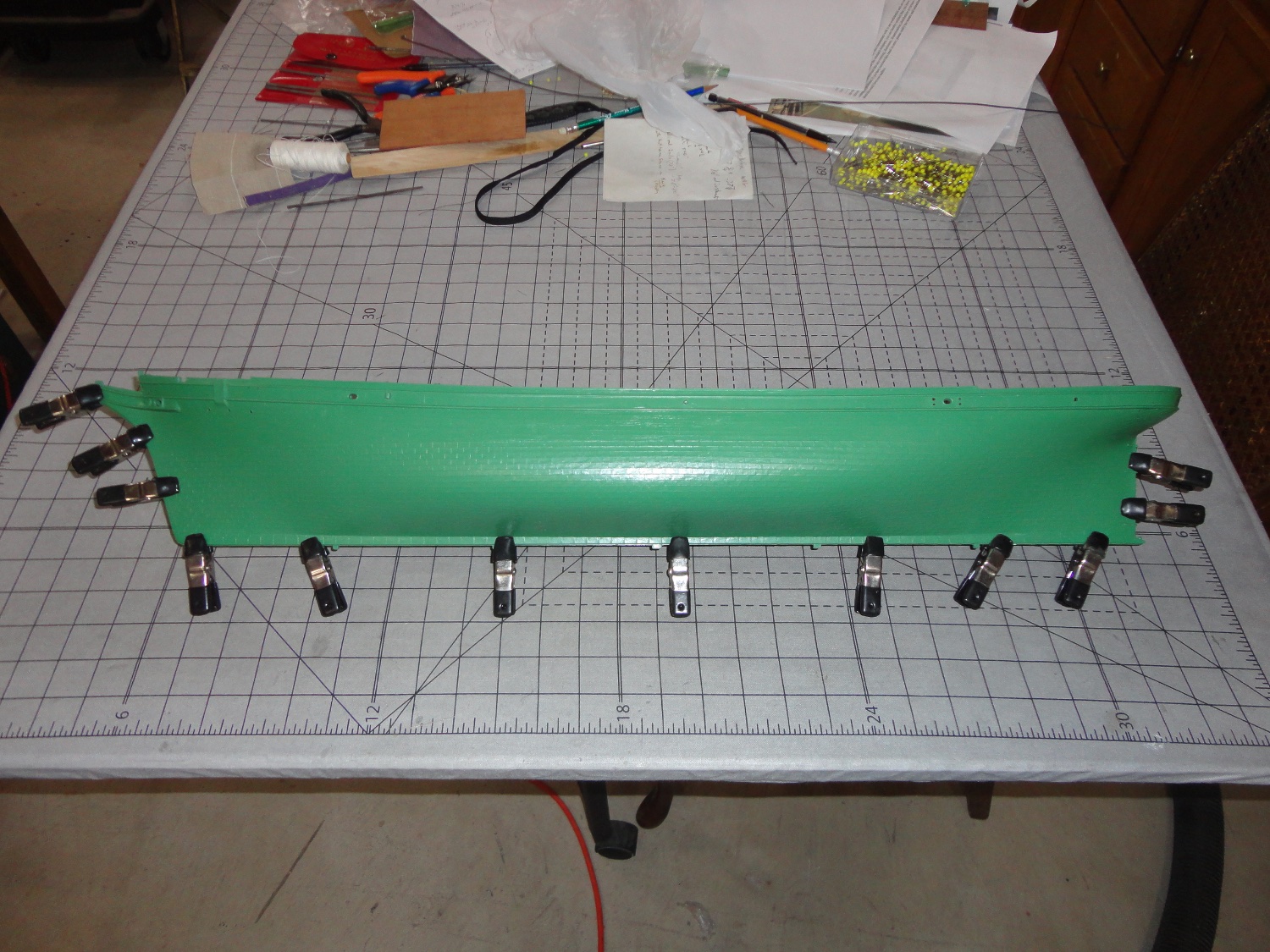
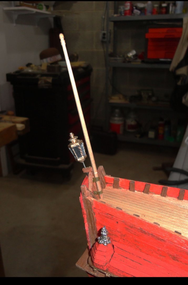
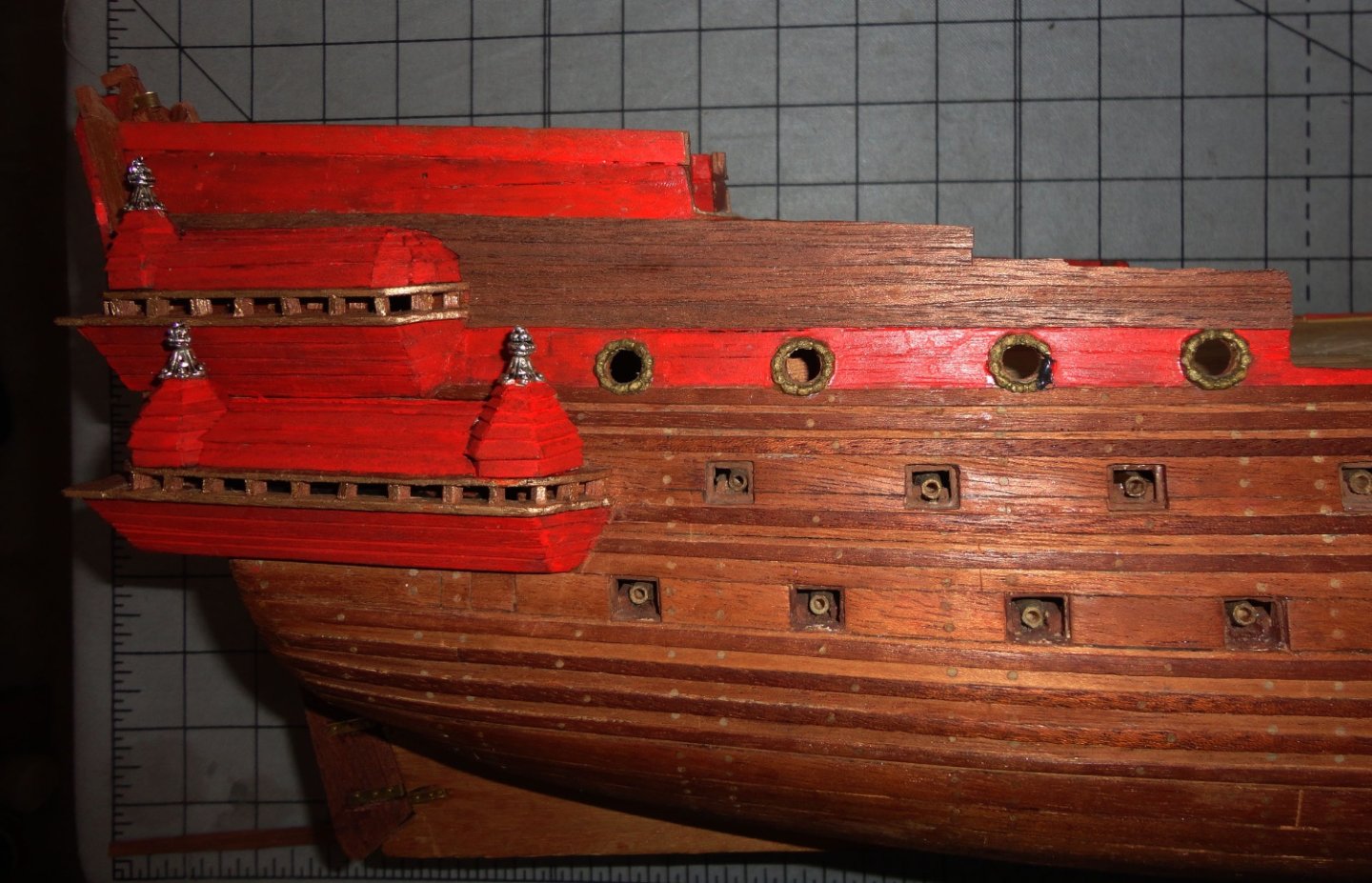
Here's a picture of the lantern and flagstaff temporarily mounted. The end of the staff was tapered and grooved for the flag pulleys - the contrast is off with the Admiral's old camera. 'Seems the upper stern of the Vasa has lapstrake clapboards, so I decided to lay on strips of walnut veneer to do this. Again, the overlapping boards don't show well in the image below - but when done and painted they will better conform to the original. The hull is going to be the salient feature of the model when done, so things that will add visual interest and detail may be a plus. The sternmost gun port on the lower gun deck had to be closed off due to where I had to place the lower gallery. But I see that there was a 'communication' port (a little smaller and a bit lower down on the original) for orders, mail and such on the original. So I could place a couple hinges on that cover for effect. After adding clapboard to both sides, I'll put in all those mini brads as previously discussed.
-
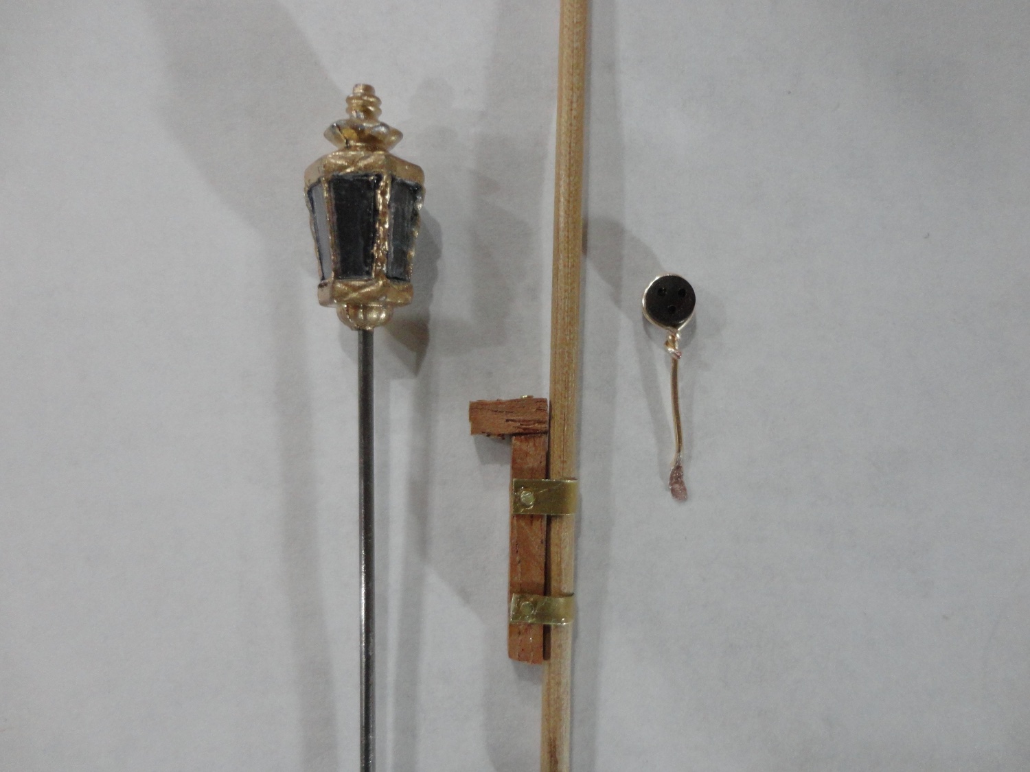
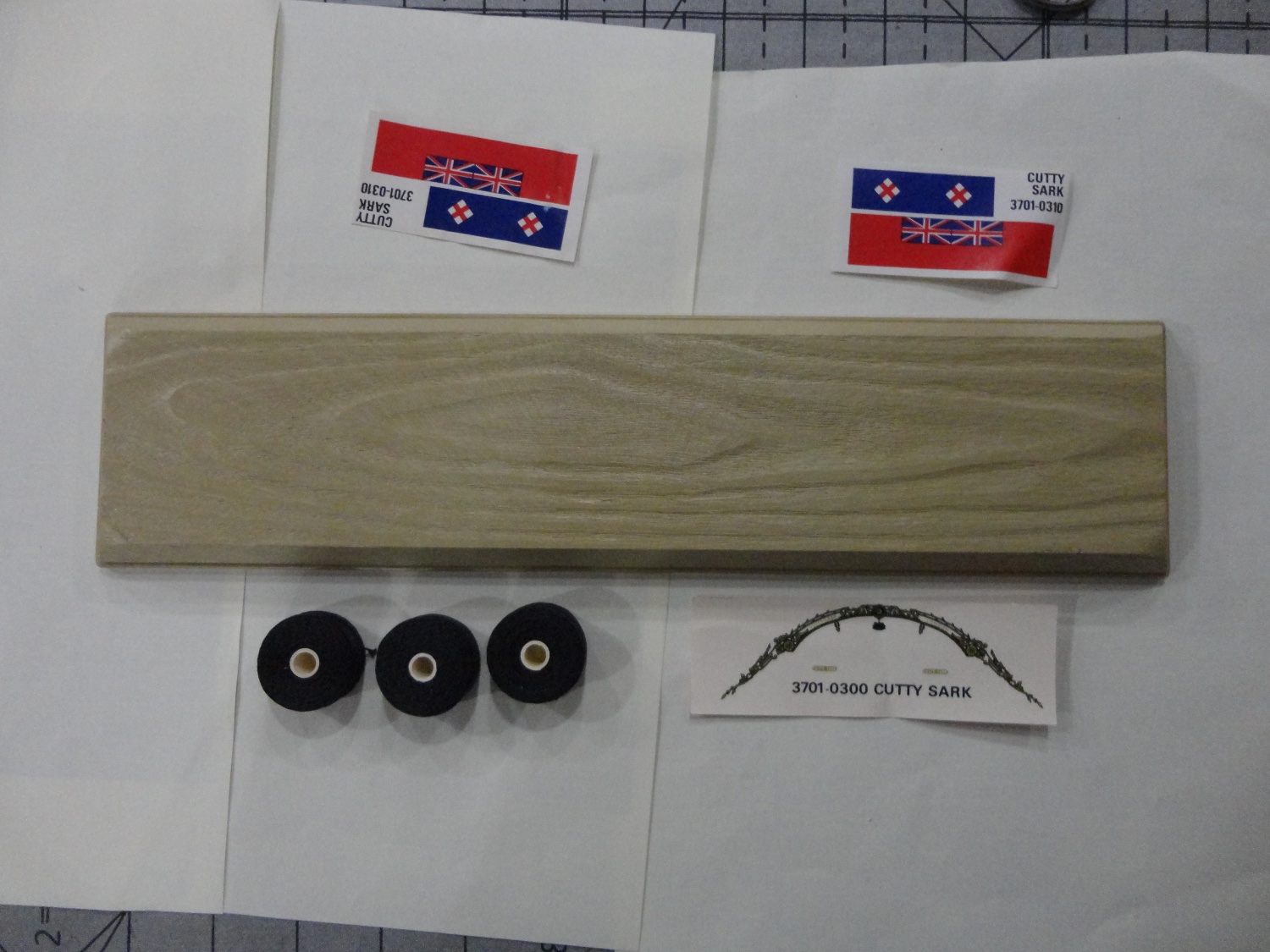
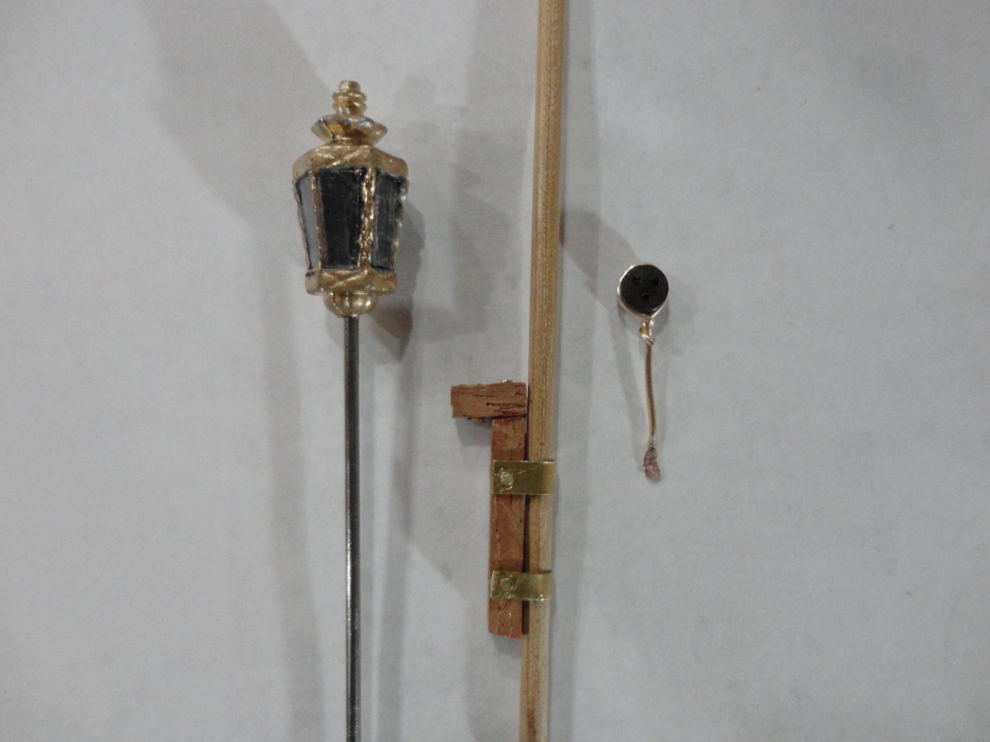
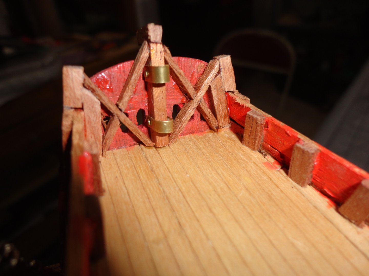
'Still shifting focus from place to place on this build - sort of like the eye of Sauron gazing from place to place in Mordor ... I don't want to 'paint myself into a corner' or make subsequent work more difficult by doing the wrong thing first. It also take time to think of the steps to do each small bit - but then once I have a good idea of what it should look like (or thereabouts), it is often a matter of jumping in and improvising as there work progresses - nip and tuck here, correct a couple things there. Apart from previously mentioned shortcomings of the ca. 1970 Billing Wasa (I'll often use Wasa and Vasa interchangeably), if someone obtained an old kit somewhere for a low price (I'm thinking of $100 or so ... a little more if it hasn't been messed with), there is a lot than can be done with forehand knowledge to improve it. Modifying some bulkheads (and redoing a few) plus adding more to conform to the ship's actual lines would be done at the outset. Make partial lower gun decks for low-detail gun carriages drilled to mount half-barrels (the portion that will show from the outside) later - and this can be done on the 1:72 kits available today ... that will look a lot better than the 'false' recesses supplied. Going to double planking will can permit inner gun ports to be cut, then the second (nice wood) planking with width closer to scale will come up just a little shy of these first openings, which is what closed gun port lids would bear against. The biggest challenge is dealing with all the figures and carving at 1:100 scale. This is where the more recent kits excel, and there is also much less to correct. I've ordered a few Kevels, a capstan and some odds and ends from Crafty Sailor. The first picture shows three items. On the left is a reasonably sized stern lantern scrounged form an A.L. parts kit - drilled to accept a steel rod I had on hand, painted, then panels of clear plastic (the sort encasing all sorts of things sold these days - rigid enough but not too thick) were cut with scissors and CA'd as glazing. In the middle is the center support for the flagstaff (shown slipped into the retaining bands) that I will taper on a lathe and turn a little ball on the end. 'Good to have this removable so it won't be subject to breakage as more work is done on the ship. The lantern will go into the small projection at the top of the flagstaff support - an will also be removable (can be glued later). On the right is a test deadeye where I just wrapped soft 24 gauge jewelry wire around, then formed the free end to widen it with a mini ball-peen hammer (planishing face opposite the ball) and drilled for a brad fastener. I note that the deadeyes on the original Vasa are not all that 'triangular', but they are nearly round ... just slightly oblong in the vicinity of the third hole. I wouldn't even call it 'almond' shape. So at 1:100 it might be be OK using round ones - 3mm would be near to scale, but the one shown is 5mm that I have a bunch of. If I were doing a 1:72 version, it would be closer to the original Vasa to abrade a little off each deadeye side to get that slightly oblong look. (I might even do this on mine.) But I would not use the 'obviously triangular' deadeyes that can be purchased (or made). These approximately equilateral triangle deadeyes are suitable for many other early ships, but in the case of the Vasa - not so much ... just saying. The shot below shows the framework in place on the inside of the stern. A close shot shows all the recent filing burrs and slops I've yet to clean up ... all the tiny warts that are hard to see when simply looking at the model on a stand. For these bits it was a matter of cutting small pieces of stock, trial fitting then CAing in place. A daub of accelerator does a nice job of instantly 'locking' the assembly done in a piecemeal fashion.
-
There is a lot of potential for enhancing this OcCre kit, as Clearway has shown on his build log. Many are always looking for more tips and opportunities on any given ship, so more logs can provide this very thing. Best of results, mate ! Johnny
- 206 replies
-
- 1
-

-
- Endurance
- Shackleton
- (and 2 more)
-
Silver soldering
Snug Harbor Johnny replied to Dziadeczek's topic in Metal Work, Soldering and Metal Fittings
Silver soldering is tricky business. I did a few samples in shop class years ago, and the workpieces have to be very clean at the start and well fluxed. We got the heat needed by using oxy/acetylene torches. -
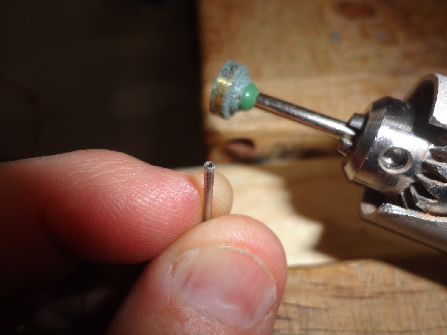
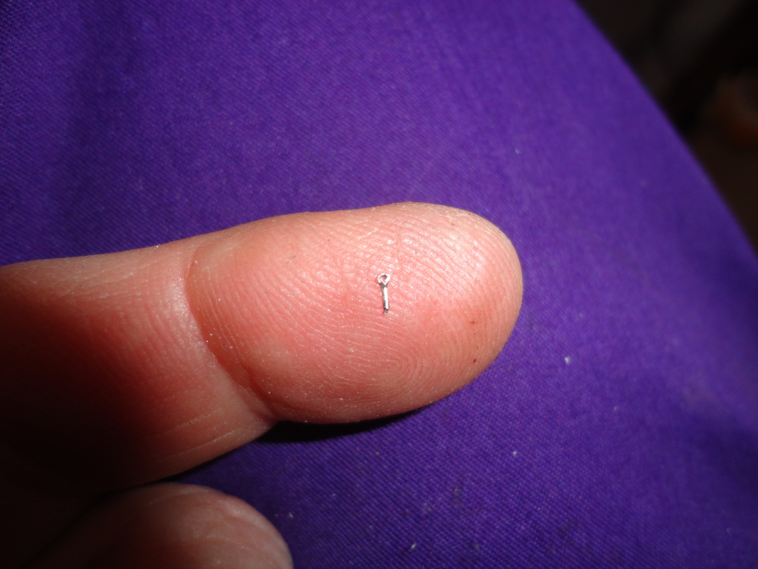
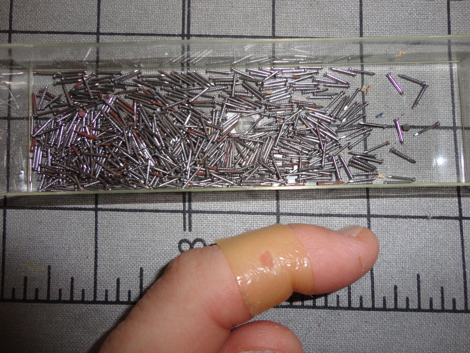
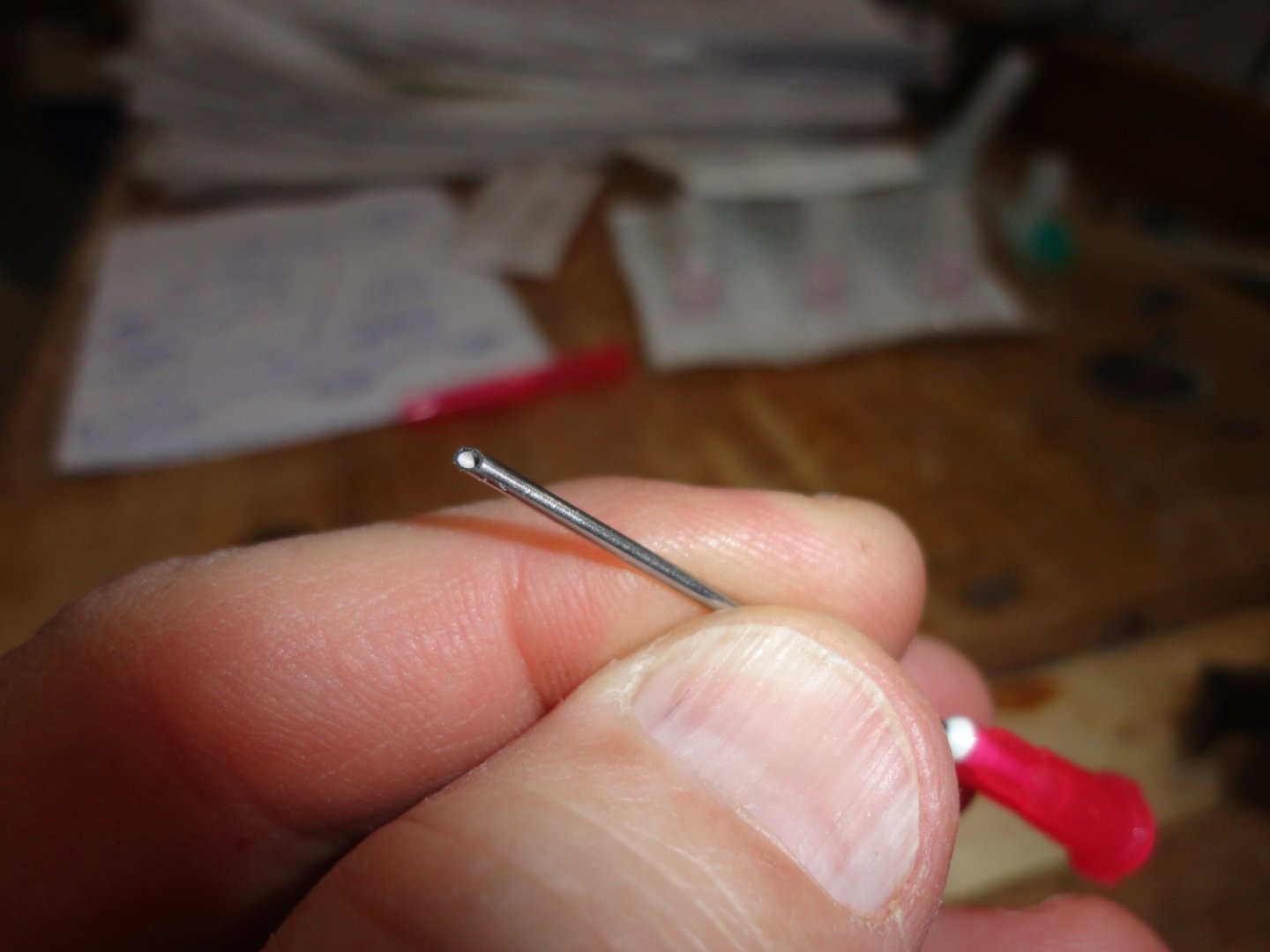
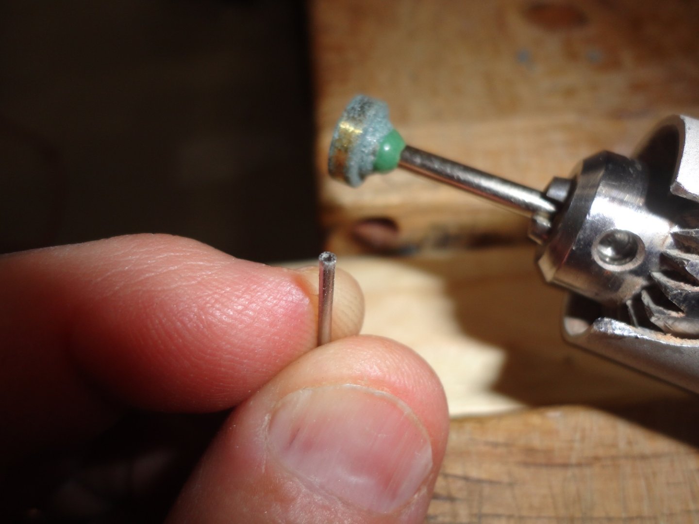
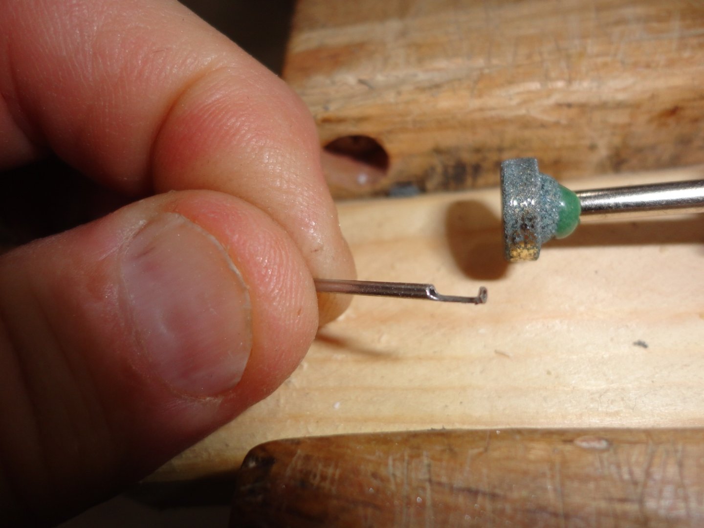
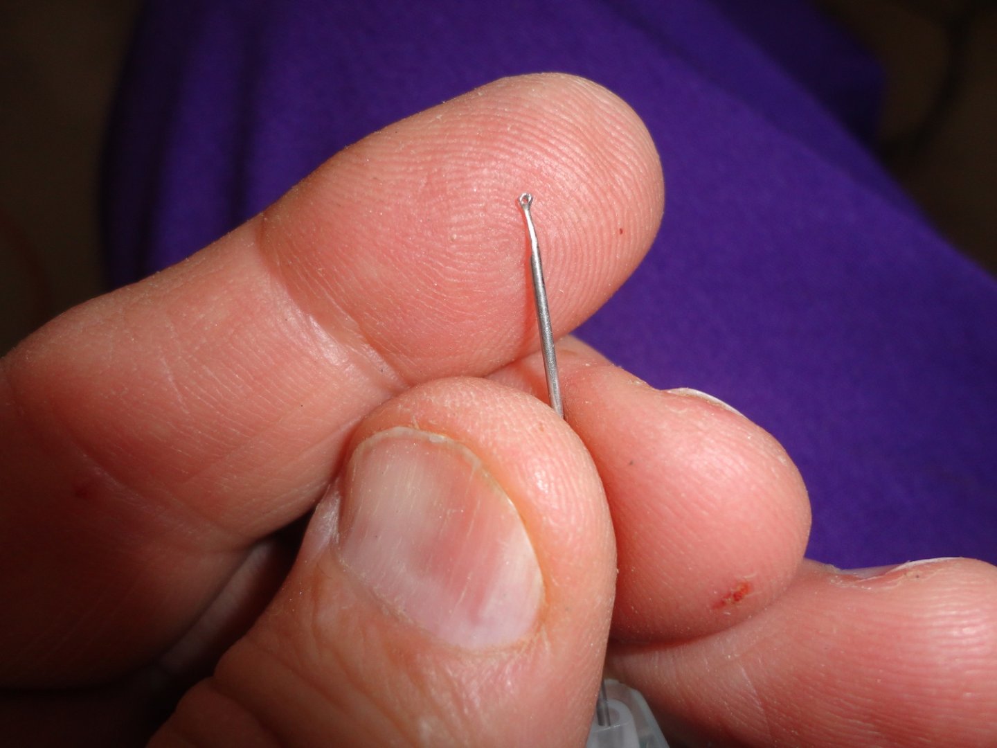
'Just messing around the man cave (aka shop) and thought I'd try an idea I had for making tiny eye bolts from hypodermic syringe needles. I thought they could be useful with the end ground flat to use as tiny gun barrels for the small guns on a Metal Earth U.S.S. Missouri in my stash. But then I was thinking (the Admiral thought she smelled wood burning !) ... what if some material was ground away behind the flattened end, then the 'eye' of the needle lumen of an 18 gauge 'blunt fill' could be bent over to form an eye bolt. A 22 gauge needle fits inside the blunt fill to help keep the eye round when bending. I've got to be careful as I've 'cored' a finger a few times before when working in an I.V. hood doing admixtures - an occupational hazard of a Hospital Pharmacy Technician. The first picture shows the 18 ga. needle. Step 2 is to grind the end flat ... nice for a secondary gun barrel on a warship. Step 3 is to grind behind the end as shown. BTW, the brass 'gall' on the stone wheel is from trimming other stuff. Bending with fine needle nose tended to distort the eye, so the insertion of a smaller needle proved helpful. Clip with flush cutters to separate. This is very tedious and the results are not perfect eyes. There are PE eyes available that will save lots of time and trouble. Also, the needle was not the biggest risk, as iImanaged to grind a bit on one finger. A great thing to put over an open wound is Dura Bond - sort of an artificial epidermis. Dura Bond is waterproof, stays on for days and allows the skin to heal in by 'secondary intention'. Below is a picture with the covered boo-boo. After a while the wound site may appear to 'bubble up' below the Dura Bond - but this is normal and allows healing. Oh, the plastic box lid contains a bunch of really tiny steel mini brads that came with the 1:100 Billing kit. They were supposed to be used for the single planking (yeah, how much did I know about fairing or adding extra bulkheads years ago), but I didn't want to used them. Now I see that the original ship had a lot of iron nails (spikes) used in construction and visible on the outside. Maybe Billings had the right idea with these brads ... but they would be best applied AFTER planking (pre-bending & shaping with glue as the bonding agent like I did it). The 'instructions' could have been a lot better, but what better instruction than to study builds on MSW? OK, so I counted them and found 556 ... plus a few extra that slipped by the tweezers I used to count them all - so the number is more like 560+. So the plan is now to allocate about 250 per side to apply and get an appearance similar to the ship on display in Stockholm (they are replacing the old iron with stainless steel to better preserver the ship). Holes will be drilled so the brads will not split the thin single planked mahogany. My smallest drill (.030) is the same size as the brad shanks, so testing proves that a slightly smaller hole is needed to provide a little interference to retain the brads. A set of 'wire drills' was ordered on Amazon using a gift card left over from Christmas - Fair dinkum ! Johnny


-
I did a VERY small scale U.S.S. Arizona from Metal Earth (completed build on MSW), so working with small, delicate (and losable) bits of metal is appreciated. On the basis of your fascinating build (I'm a Civil War buff), I got this kit to do some time between other projects. (The larger metal Missouri is in my stash as well). Great tip on using CA as required. I found that kneadable JB weld epoxy putty can be mixed in small amounts to stabilize certain parts of a metal build.
-
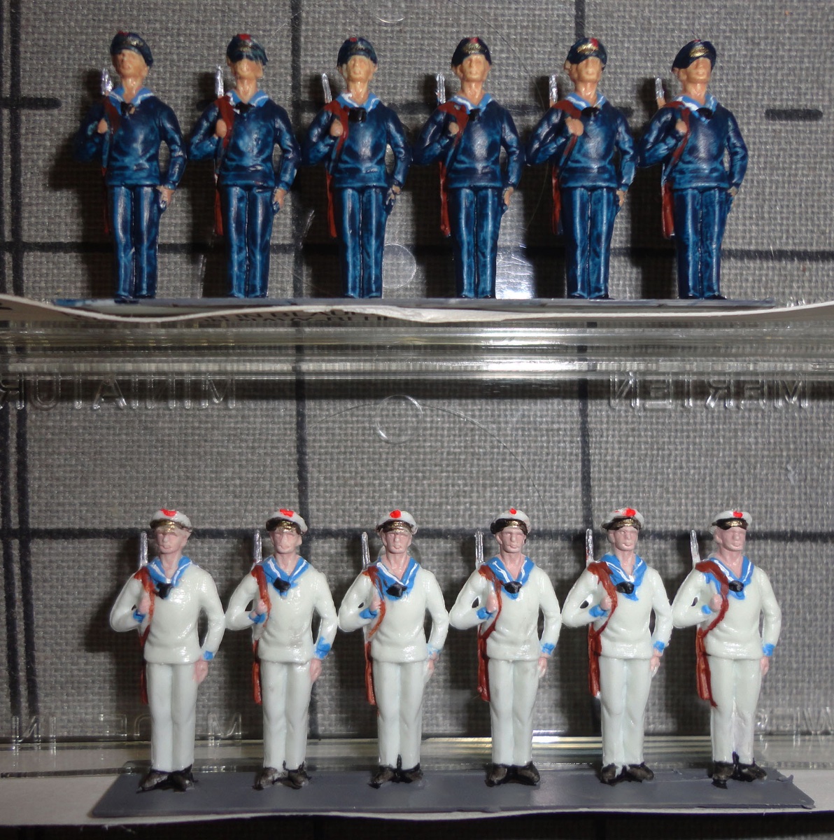
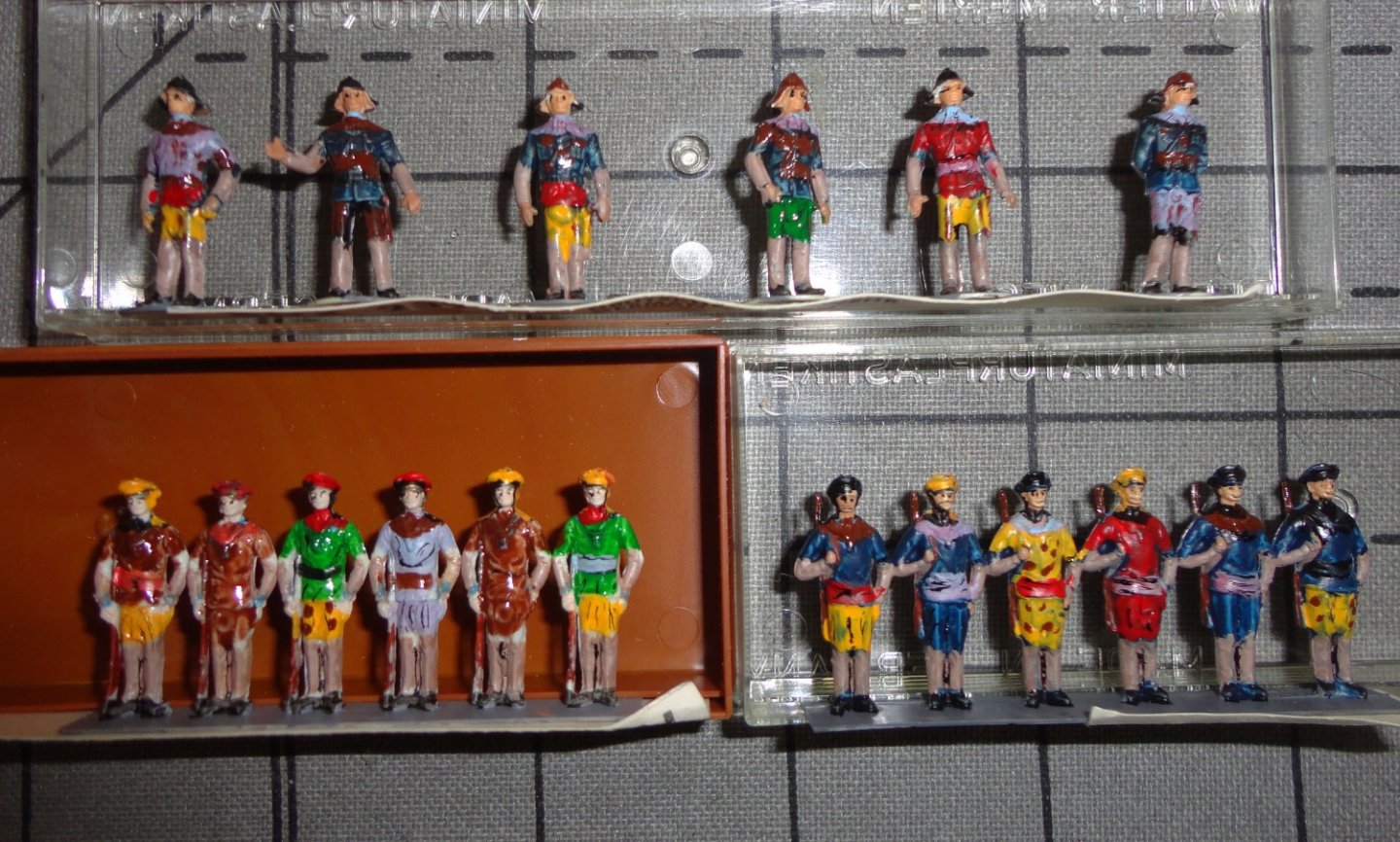
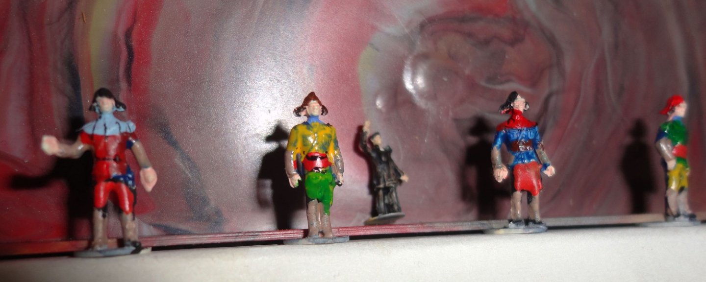
So I got out those boxed figures to see how I could re-paint them to be approximately OK for my build. On 'old school' hobby shop is still in business in a nearby town - mostly because the son of the owner decided to keep it going as a business ... they have a LOT of 'old stock' as well a new stuff aligned to fantasy gaming. Quite a mixed bag, and these stores are disappearing one by one as Hobby Lobby and other chains become dominant. Still, there are lots of things available on the internet - old stuff as well as new. The picture below shows two groups of HO scale military at attention - all manufactured and painted in Germany - and another group not shown are firemen. 3 figures of this size should stand on either side of the cherubs (or are they putti ?) beside the wheat sheave on the stern. BTW, the babies are naked on the original but I decided to give them loin cloths (diapers ?) for modesty's sake - and didn't want to model little privates for them ... not at 1:100 scale. You know, Steve from down under (aka Louie da Fly) is working on Henry Grace a Dieu where the original was nearly the size of the Vasa ... but in 1:200 scale !!! Size does matter, mate. Now the figures on the Vasa represent Emperors, classical Heroes, fighting men and such ... most with bare arms and legs beyond tunic arms or skirt. So I mixed some flesh color (not too light, since they'd likely have sun tanning) to paint on the figures arms and legs. On the ones with legs close together or relatively close, some gel CA was dolloped to fill the gap and treated with a touch of accelerator to lock in place. Then tunics (hauberks, kilts, whatever) were painted in polychrome - from looking at other builds, a lot of different colors are used - so I let my imagination run wild. Some of the figures stand together on a base, and others have little bases of their own - both fit into a little gap in one half of the box, so it served to hold a group of figures together nicely. I held onto the plastic box half with one hand and painted enamels with the other. The finished HO figures are pictured below, and they may be good enough to pass on the model. Then I had to paint the N scale (N-gauge RR) figures that go in various places around the stern. That was finicky, but then there are some Z scale figures that go at the bow - one of them (as yet unaltered) can be seen in the shot of the N scale figures below. I won't mount any of them just yet because there are a lot of things to do that require manipulation of the hull. Have to think of the 'order of assembly' - which things to do first to make later progress easier. So we'll see how long it will take me to 'putter through' all that.


-
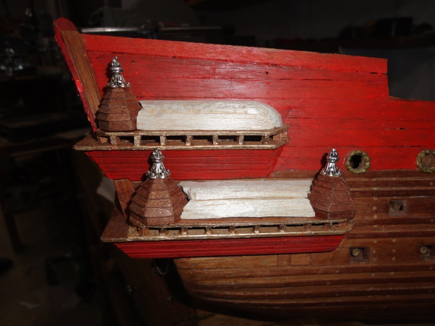
Hello again, The cupolas were glued in place (titebond) and I cut some balsa 'filler' to serve as a support for the roof clapboards that need to go on. Another approach might have been to make small frames, then plank them - but the balsa was handy and won't show. The planking with mahogany veneer was a little fiddly in places - as it was doing the cupolas. I started using aliphatic resin, a 'go to' glue for wood-to-wood applications - but it takes a few minutes to 'grab' and I found myself using 'finger clamps'. Still, the smaller pieces for the end of the upper gallery would tend to move, and before installing the next row in any case - I had to let the glue cure at least an hour because some trimming and cleanup was needed before moving on. OK, so I thought I'd try using gel CA which bonds much quicker. (Note that even dry wood has some moisture content that aids in CA bonding.) Once positioned, a dauber was used to transfer a very little 'accelerator' to the edges of the last clapboard glued ... and there was an almost instantaneous solidification of the CA. I could do trimming, filing sanding right away. I know of recent CA discussions on the site, but there are some times when it comes in handy, as there are times I used 2-part '5 minute' epoxy and even kneadable epoxy (JB) as a filler. 'Guess its a matter of whatever works for the builder. Anyway, the roofs are done and I applied some flat acrylic paint ... and things are looking ever more 'Vasa like'. I glued in the turned brass half-cannons astern for the picture this time. It occurred to me that the somewhat larger (and improved) Vasa kits sold these days have all the small figures of various sizes needed to decorate the places on the ship where ornate carvings were used. What I've done so far was hand-sculpted and tedious, and the process of making the many dozens of various kinds of figures, etc. is daunting. The approach will be to use some HO and N scale molded military (among other) figures re-painted to look more like Emperors or whatever, then bond them around the stern roughly where they appear on the original. This leaves something to be desired (as often happens), but at 1:100 they should be adequate - and certainly better than nothing.
-
I read about how Charles Goodyear 'changed the world' in a big way with Vulcanization of natural rubber. Yet he never prospered from all his work, since once an innovation is made public there are many who capitalize on it for their own benefit. Suffering the adverse effects of years of exposure to dangerous chemicals, Goodyear collapsed at a hotel in New York City on July 1, 1860, dying later that day. At the time of his death, he was 59 years old, penniless, and deeply in debt. The Goodyear Tire and Rubber Company, founded in Akron, Ohio by Frank Seiberling nearly 40 years later, was named in honor of Charles Goodyear. Neither Charles Goodyear nor anyone in his family was connected with the company. Reflecting on Goodyear’s achievements, the historian Samuel Eliot Morrison wrote, “The story of Goodyear and his discovery of vulcanization is one of the most interesting and instructive in the history of science and industry.” But, as he added, “It is also an epic of human suffering and triumph, for Goodyear's life was one of almost continuous struggle against poverty and ill health.” Goodyear himself was philosophical about his failure to achieve financial success, writing that he was not disposed to complain that he had planted and others had gathered the fruit. “The advantages of a career in life should not be estimated exclusively by the standard of dollars and cents, as is too often done. Man has just cause for regret when he sows and no one reaps.”
-
You are very resourceful, imaginative and skilled. Kudos !
- 59 replies
-
- 4
-
-
- Revell
- Constitution
- (and 1 more)
-
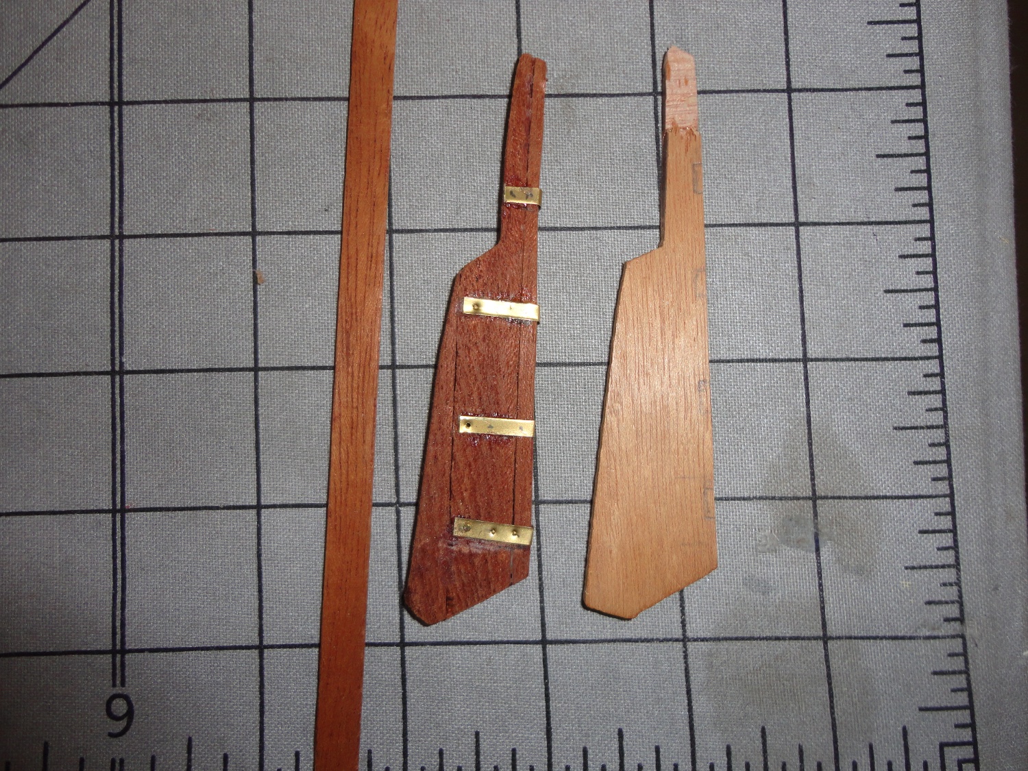
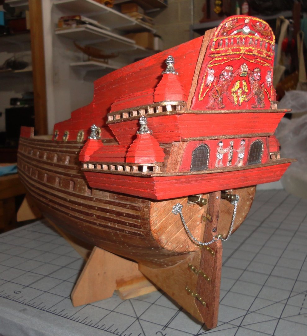
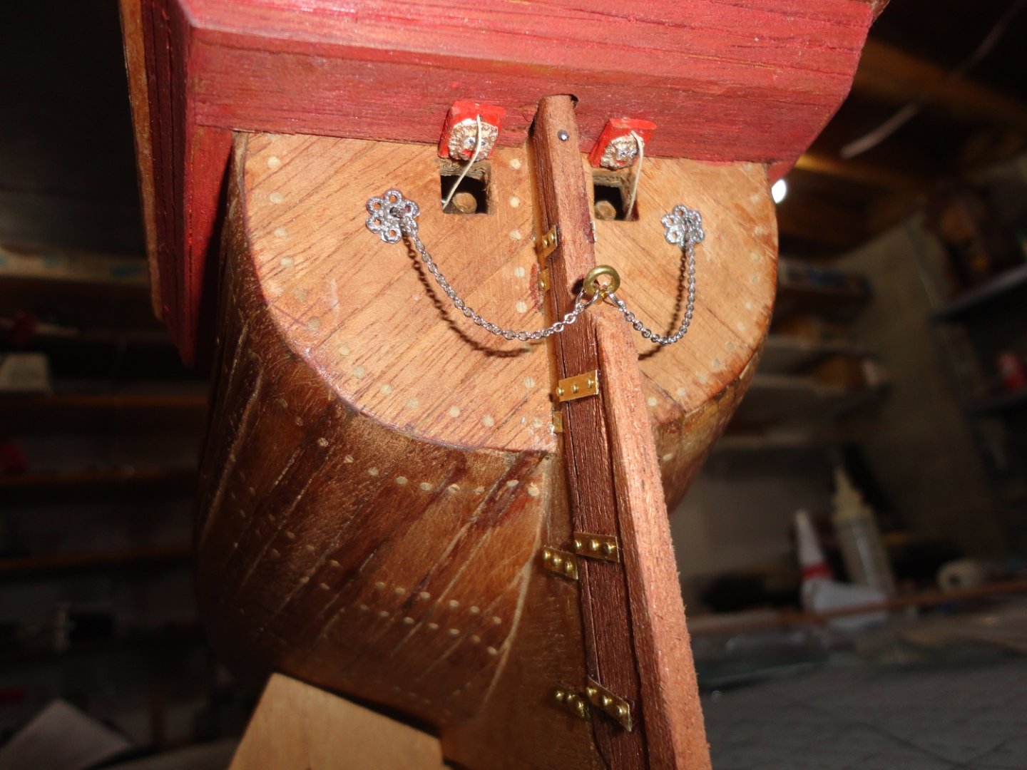
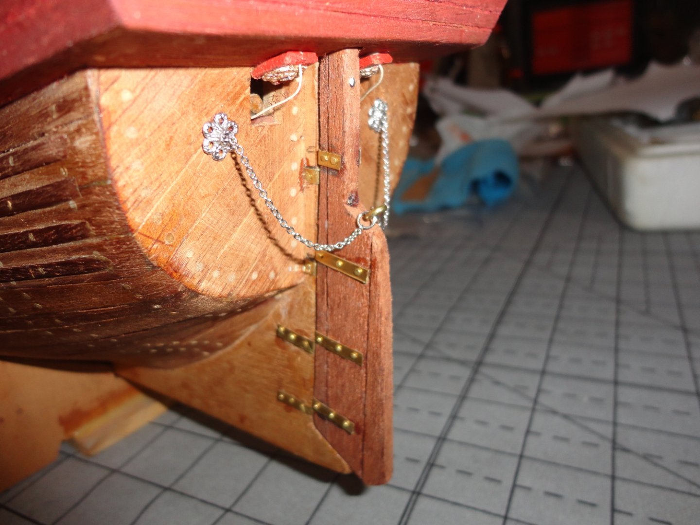
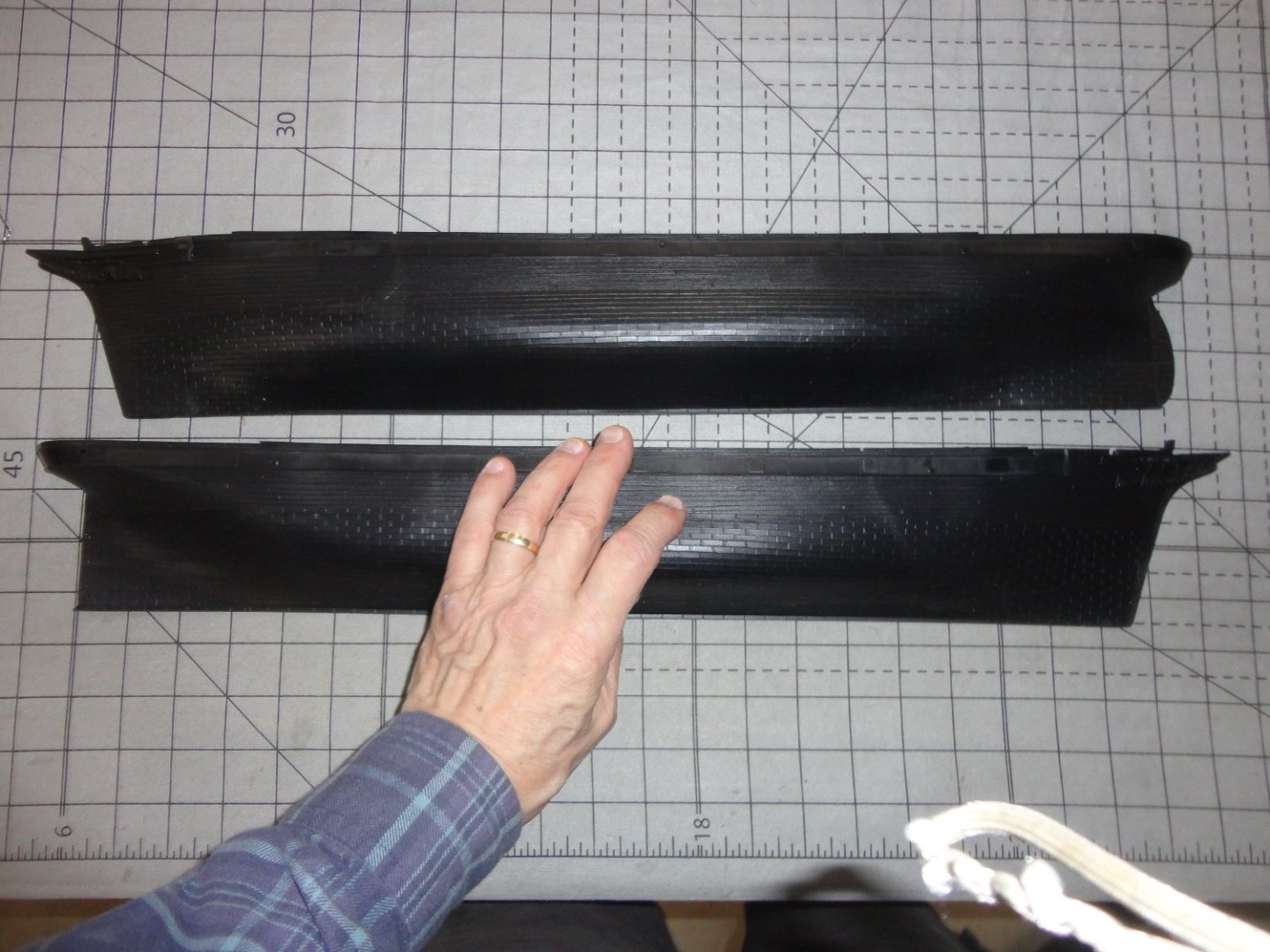
I see that my last post on this 'build' was March, 2022 ... and its been nearly a year. 'Lots of learning and intervening tasks have happened - and participating in MSW has been a fascinating diversion. I have some plans on projects to come, and I've resolved to finish this present one first before moving on - which will give me 3 out of 3 completed MSW builds. As stated elsewhere on other threads, there are some major gaffs in this earliest version of the Billings Wasa (the Swedes prefer Vasa - take your pick) - and rather than try and make the masting and rigging kosher when the inaccuracies from the deck down are not correctable for the most part, the idea is to represent it still 'under construction' in dry dock. That means having the first sections of masts plus fore stays, shrouds and ratlines (not unlike what is seen on the restored original) on a substantially complete (but not fully fitted out) hull. BTW, the Vasa kits offered these days in a slightly larger scale are much better than the ca. 1970 version I'm puttering around with. Theres nothing like renewed interest and a sense of direction. So I decided to continue working on the stern area and work forward. The kit rudder was mere plywood and broke while trial fitting, so I made a new one by laminating left over planking mahogany and cutting it out with a small scroll saw - a Dremel scroll I got from my dad, which is noisy but works well enough for occasional cut outs. I'm not opposed to taking a few shortcuts (I'd rate myself as a permanently 'intermediate' modeler, so 'good enough' and 'standoff scale' work for me) - and I decided to shear some strips of thin brass shim on a paper cutter to bend around the rudder and matching keel area (offset, of course). The picture below shows the original part, the re-made part and a strip of the stock used to do that in three layers. (I love mahogany for a wide variety of things - but certainly not for decking.) The brass strips were CA'd in place temporarily, marked with pencil, 'linked' lightly with a prick punch and just drilled through with a wire drill for putting tiny brass plated brads into. The new ridder shows some of these steps. As noted in another thread on glues, smooth metal does not offer much 'grip' for Duco or CA ... maybe Epoxy might have done better - but it occurred to me (too late) that lightly sanding the underside surface of the metal before bending would have given it some 'tooth' for the cement to adhere to, as the process of even light punching caused glue failure in places. (A little de-burring is also a good idea - note to self for later.) So I had to nail (with the aforementioned brads) from the outer edge on both sides and work my way in. Also said elsewhere is that I don't want to go through a whole bunch of new pages to wrap up this build, in part because the techniques are familiar to most. The stern geometry I'm stuck with left little room for the two rear gunport lids, but it gave me practice on how I might do all the ones needed for the sides. I took a piece of planking stock the width of the ports (which were made exactly one plank wide some years ago ... yeah, out of scale) and drilled a tiny hole with a wire drill on either end (as I wanted to make 2 lids and holding the plank was a convenient way to work) for the pull rope. No need to make the opening rope since there would be no way to see it. Before passing a line through and knotting the end to prevent pull-through, the periphery was painted with scarlet acrylic. I recently got some modeling flat paints in acrylic, as Testors enamels seem to be all gloss and take longer to dry. I glued a small lions head previously molded in dental plaster (similar to Durham's water putty) in a latex mold I made of a master sculpture in plasticine clay, and painted the lion's head in metallic gold - with white eyes (and a dot of black for the pupils) plus a little red in the mouth. When dry, I simply cut the port lid off the end of the stick with a fine saw (Atlas track cutter for O-gaige model railroad track). The lids were glued in place (BTW, I used CA for all the gluing - gel type), and the pull lines stuffed into the opening and glued to one side. There are half-cannon barrels that fit into the 'dummy' gun carriages with dowel receivers. The dummies are visible through the ports, but I have not yet glued in the brass barrel halves that will protrude through the gun ports. The rudder was pinned in place with 3 thin iron nails - drilled first - (yup, why fuss with pintles (or are they gudgeons) when (at this scale - 1:100) they'll look well enough. BTW, the brass plated brads were harvested from an AL kit used for parts and stock. I found a threaded brass eye (from a Steingraeber parts kit) to mount on the edge of the rudder to accept the rudder chains - which were found in the jewelry section of a JoAnn's fabric/craft store. Two holes were drilled to either side of the rear cannon ports (where fittings are on the original ship), jewelry fittings were slid over the chain before stuffing the chain ends into the drilled holes and CA glued (accelerator provides REAL quick setting !). Then the fittings were slid unto cover that and glued. The picture below shows the result of a good day's work in my shop. It seems that around 27.5 degrees (or thereabouts) is the maximum that a rudder should turn to either side before it become both an inefficient brake and an inefficient rudder. Rudder chains are suppose to limit travel to either side. The second function is - in case rough seas cause a rudder to become unseated and come off - to retain the rudder and keep it from being carried away ion said rough seas. 'Funny the stuff one can learn in the process of modeling. I won't go into the list of boo-boos, but rather think there is a certain 'charm' to it, at least in my eyes. Two more pictures of this area appear below. Fair sailing ! Johnny


-
Cordless Micro Drills
Snug Harbor Johnny replied to CLovehitch's topic in Modeling tools and Workshop Equipment
The 'Chicago ' variable speed flex-shaft drill (sold at Harbor Freight) I've enjoyed BOTH power and lower speeds (modulated by a foot control - like my 'old school' sewing machine). I do have to use an Enco mini pin chuck (has three small collet sizes) to use 'wire drills' for the best results. Yeah, there is that flex shaft attached to the motor that hangs from a provided wall hook. 'Same would be true for a old-style dental drill ... my brother got that from my dad's estate 'cause he was there first. -
Per the History Channel, late in the 19th century they tried using nitrocellulose as a substitute for ivory billiard balls. There were pool games that had explosive results when the impact from the cue ball was too great !
-
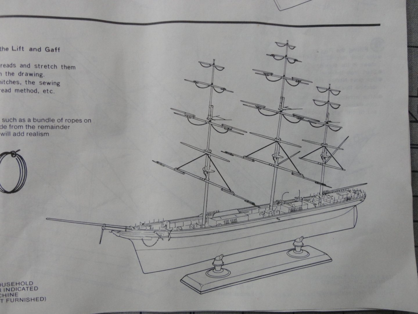
The 1:96 Revell CS has masts that one 'builds up', so I wonder why choose a given position and then bond (glue) the yards permanently in place? I've seen a couple builds where the yards were modified so that can pivot - thus be adjusted as one re-thinks exactly what angle is to be depicted. The rigging might even be made to function as to allow adjustments. I have a suspended build to finish before I do anything new, but continue to read, study and look at other builds with great interest - which certainly helps to "learn the ropes".
- 248 replies
-
- 3
-
-
- Cutty Sark
- Revell
- (and 2 more)
-
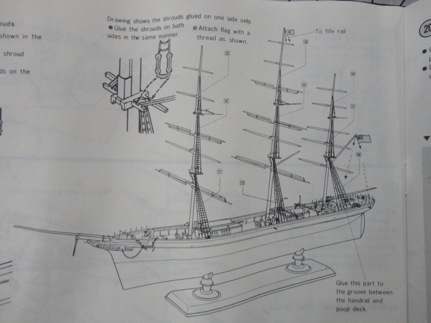
Cutty sark mantua sergal 1.78 Rigging
Snug Harbor Johnny replied to Milo's topic in Masting, rigging and sails
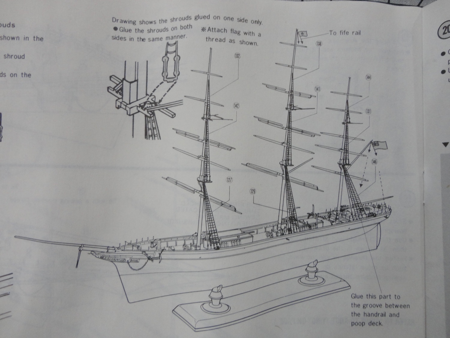
Reference Noel C.L. Hackney's book Cutty Sark - Classic Ships and How to Model Them (#3) in the series - which was originally meant for the 1:168 Airfix plastic model to be substantially enhanced to conform to the extant CS ... but takes a very skilled miniaturist to accomplish at such a small scale. However, the same book can be used for larger scales successfully. I'm studying it on and off and can relate the following for the mizzen yard lifts - rigged the same as the fore and main yard lifts (for the course - or main sail). The masts all have a mast band accessible from the deck with belaying pins all around, and these correspond to attachment points on a ring of mast foot eyes almost at deck level beneath the mast band with belaying pins. Finding a picture of these items aids in understanding. Belaying pins on the mast band of all masts for the port and starboard yard lifts are the ones located directly port and starboard. A line for the yard lift on each side of the yard is attached near the end of the yard, then routed up to a 10" (at full scale) block attached to an eye on the lower mast cap, then down through the the top (mizzen top in this case) and attach the end of the line to a 9" double block roughly halfway down the mizzen mast. Then, from the becket of a 9" double block hooked (or otherwise attached) to the proper mast foot eyebolt (port or starboard as applicable), make a double purchase between the two blocks (that is, from the top eye of the lower block up to the hanging double block, then back down to the lower block - 'first purchase' - back up to the upper block and down again to the lower block - second purchase). End by taking the fall (free end of the line) from the lower block directly to the mast band pin and belay. 'Hope this helps. -
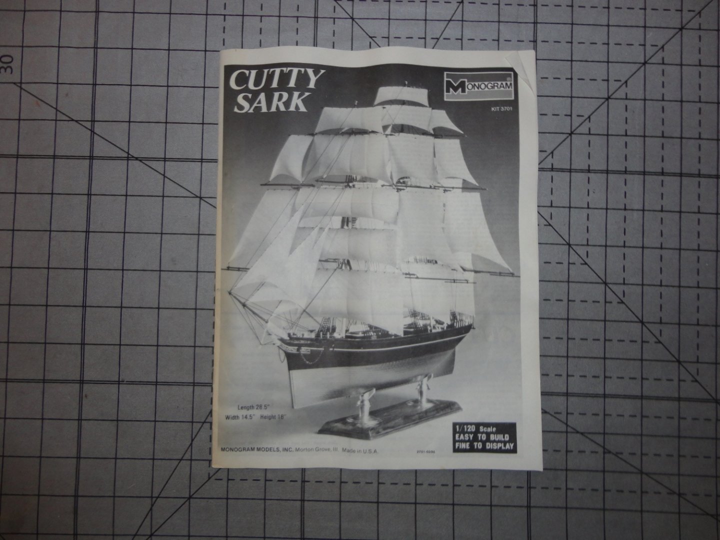
Ahoy Michael ! The kit review has been posted for the 1:120 CS Monogram version in the kit review section (plastic). 'Hope it servers for now. Johnny
-
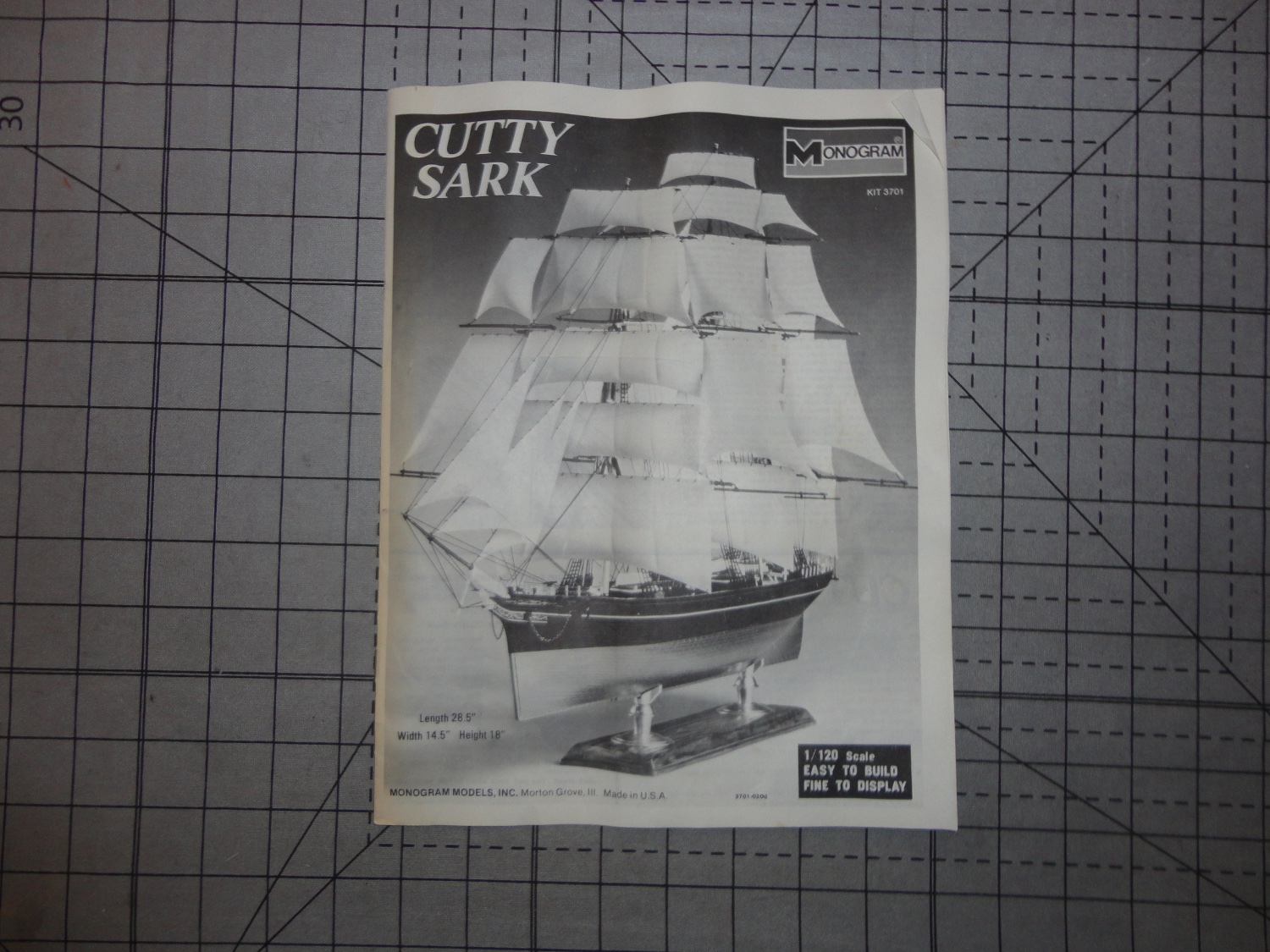
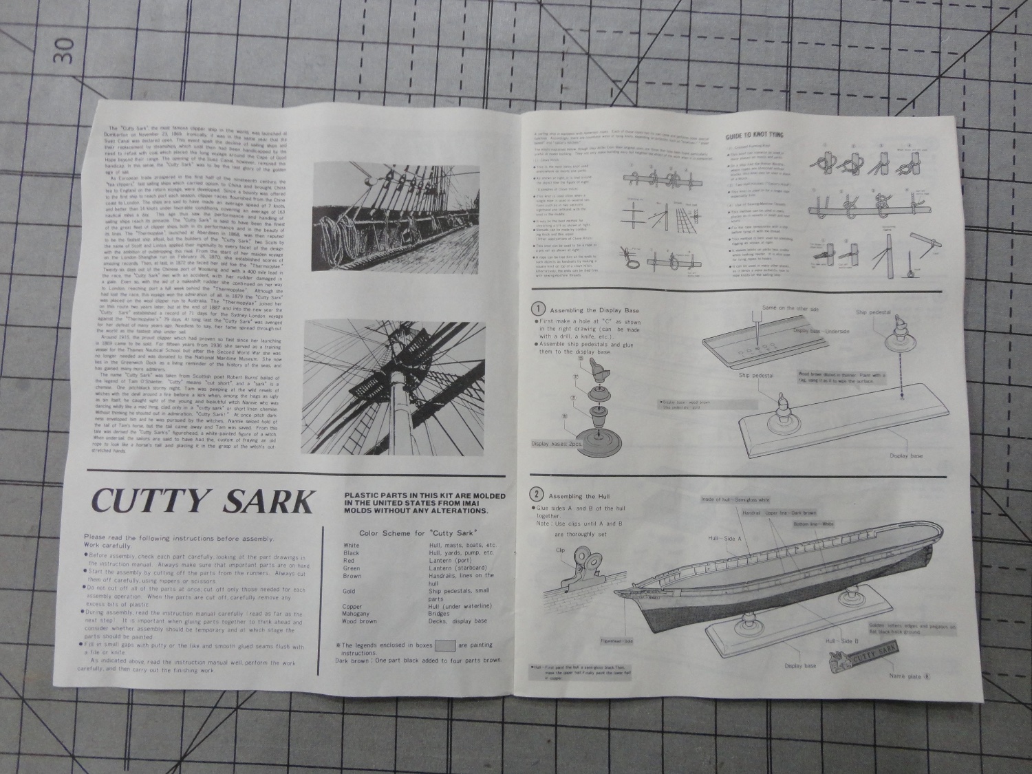
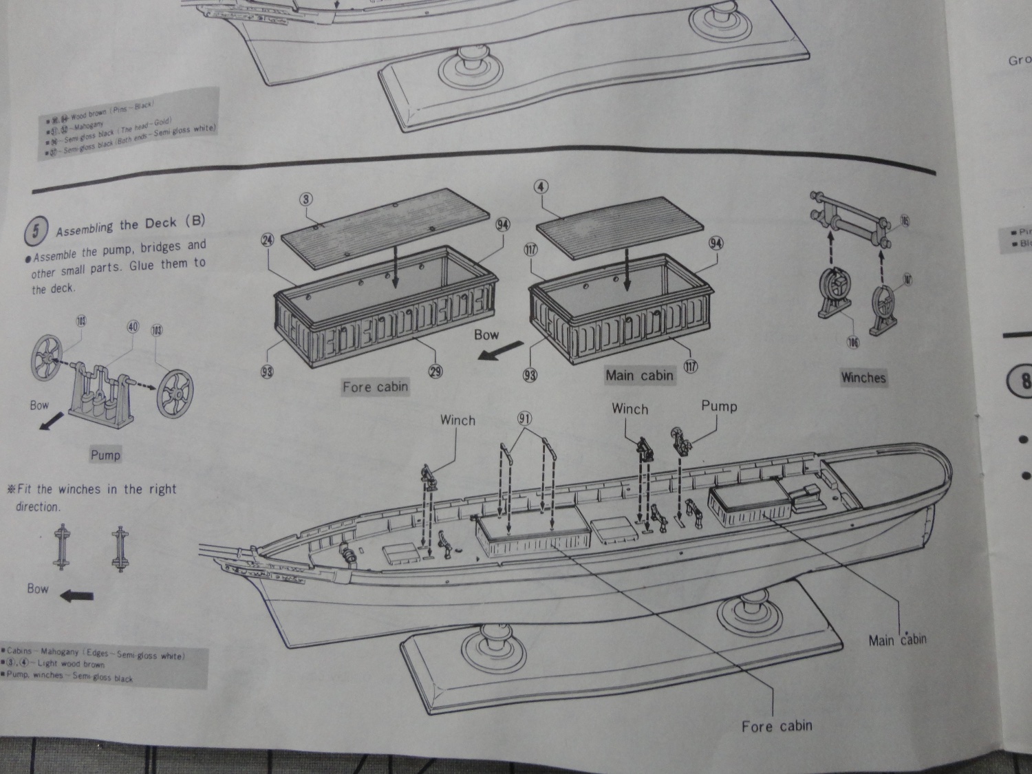
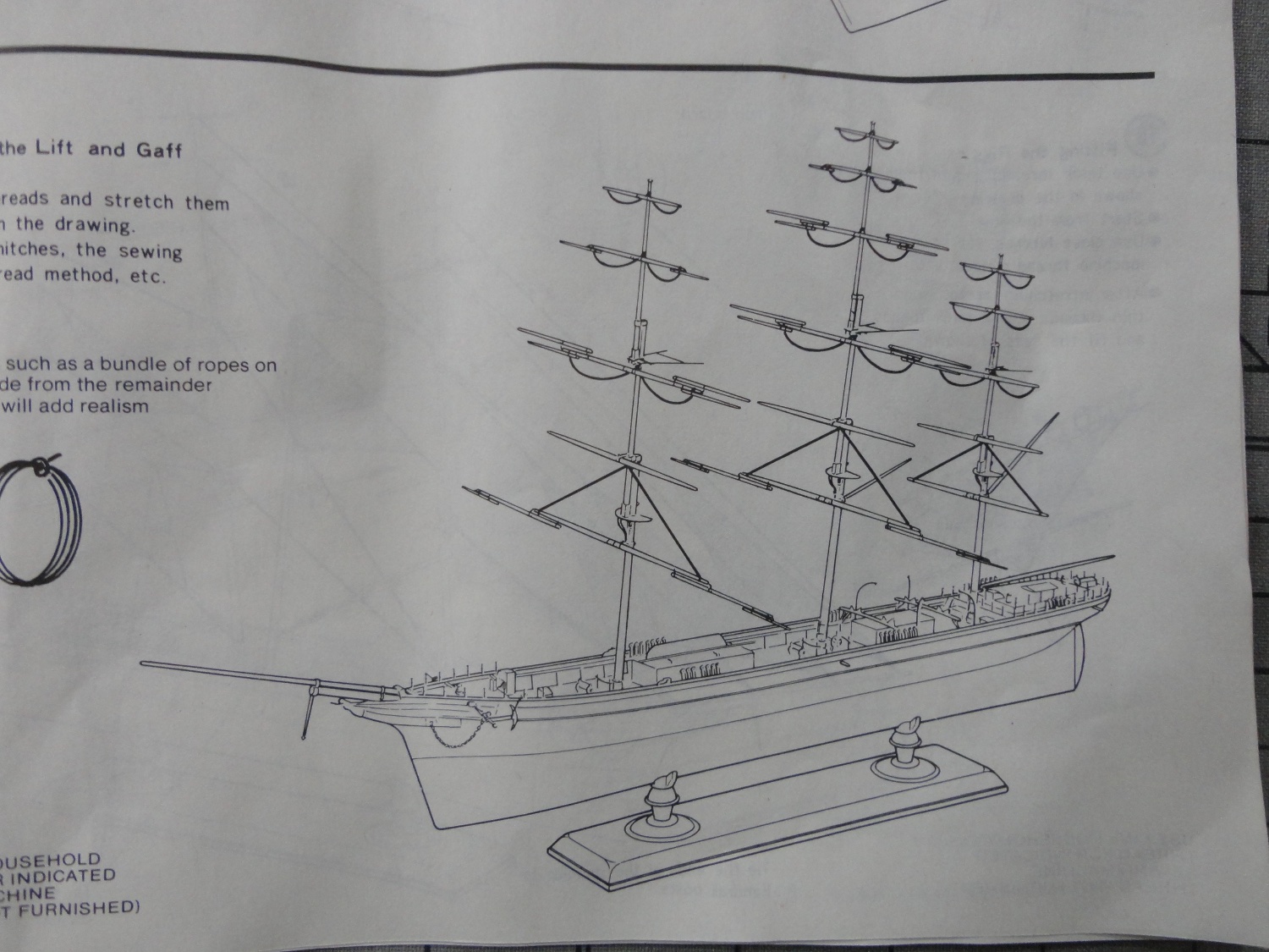
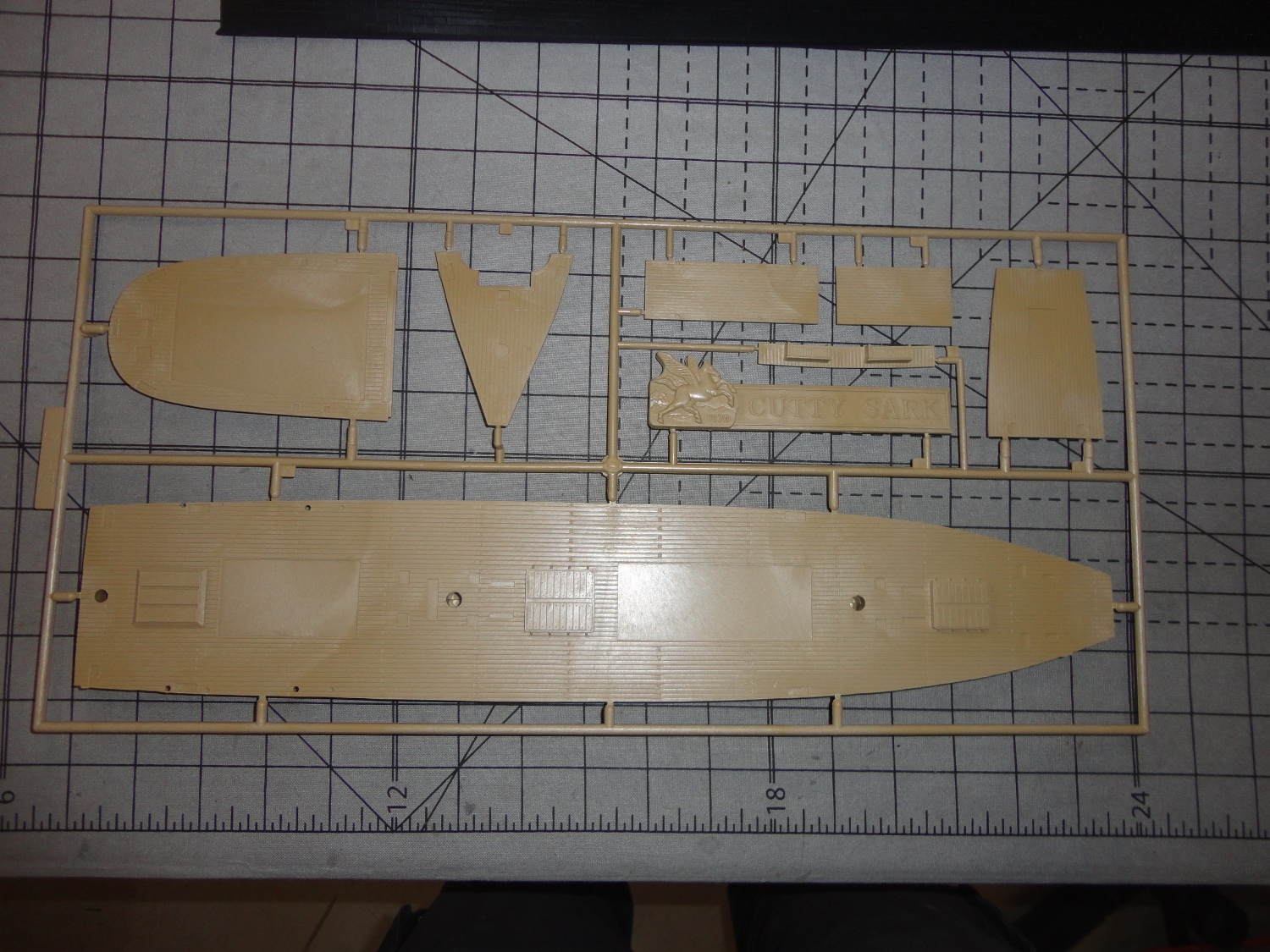
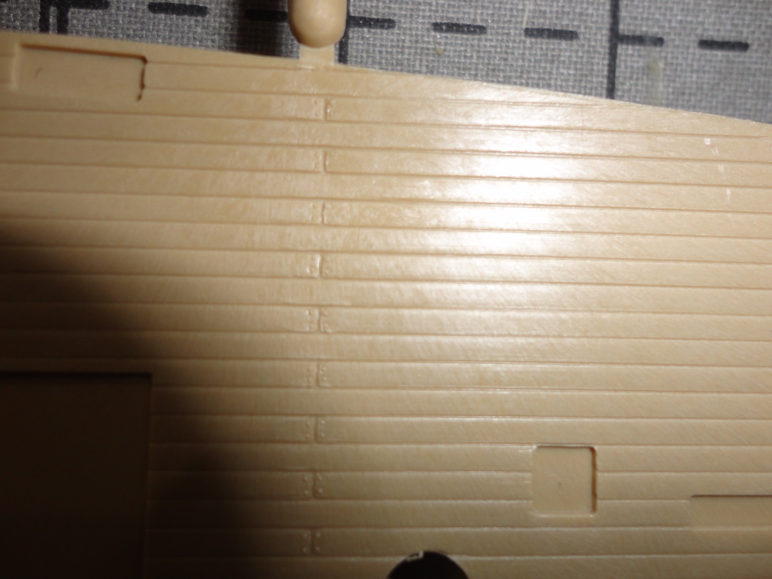
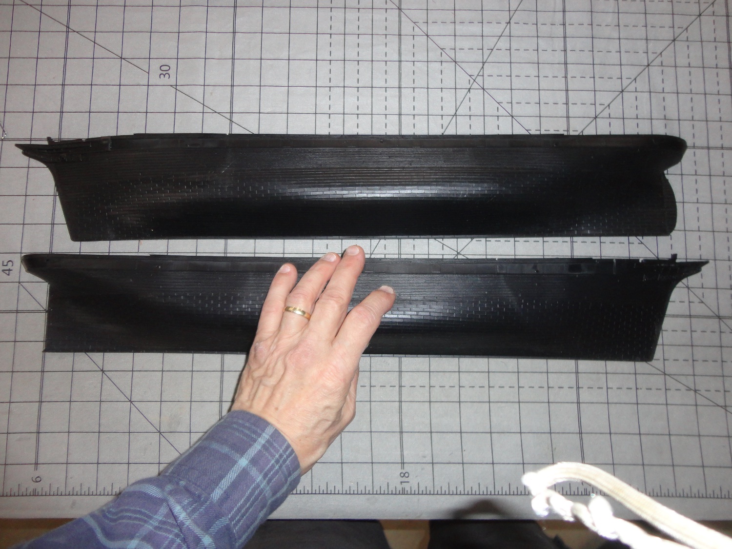
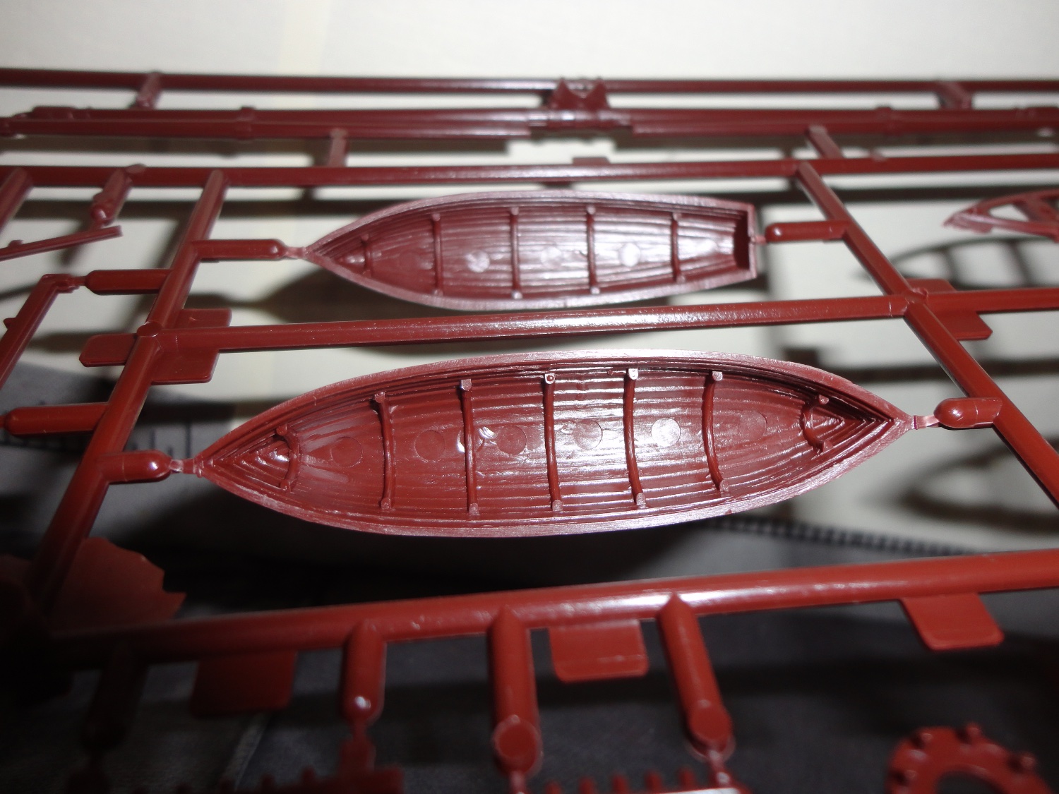
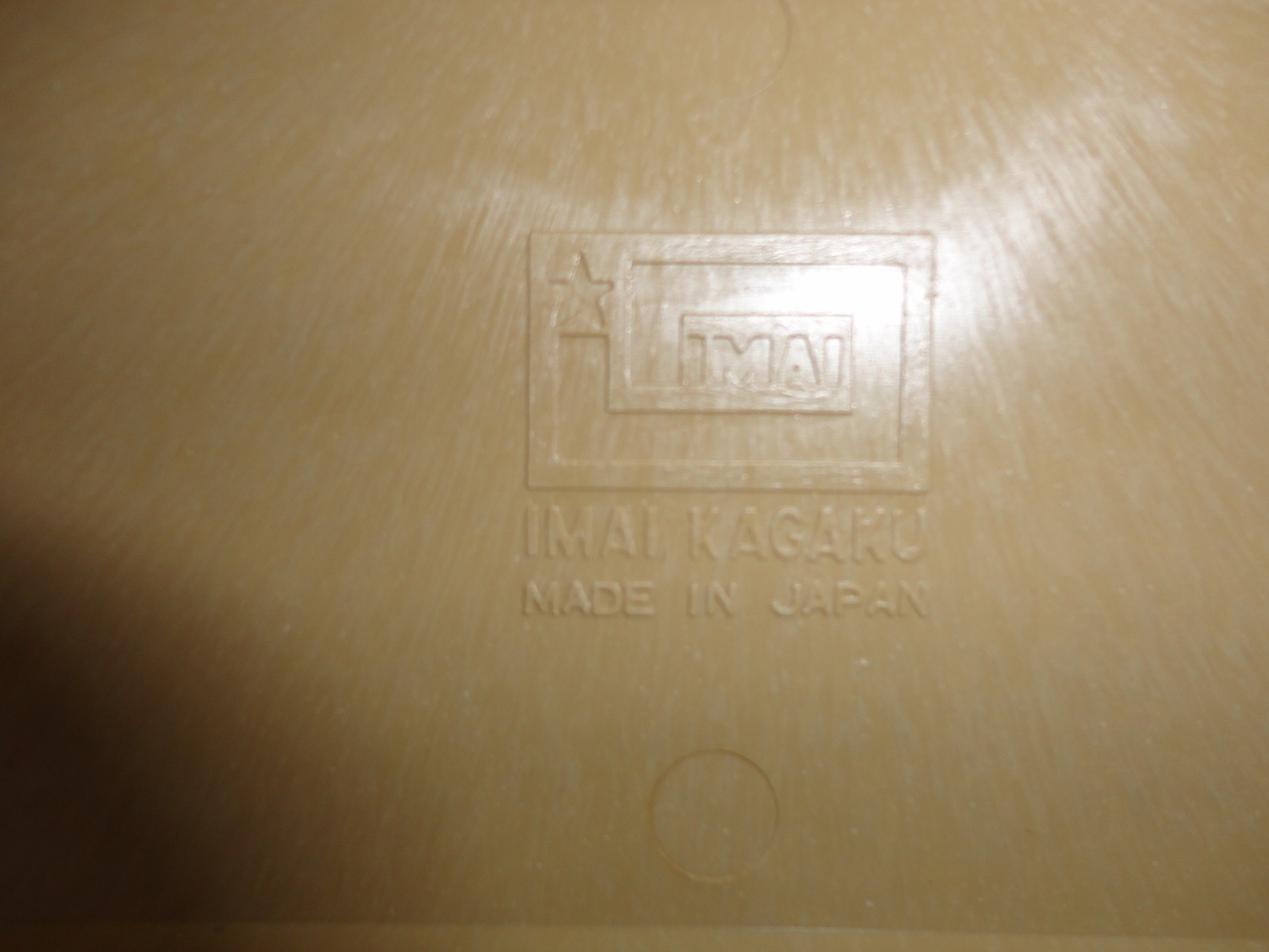
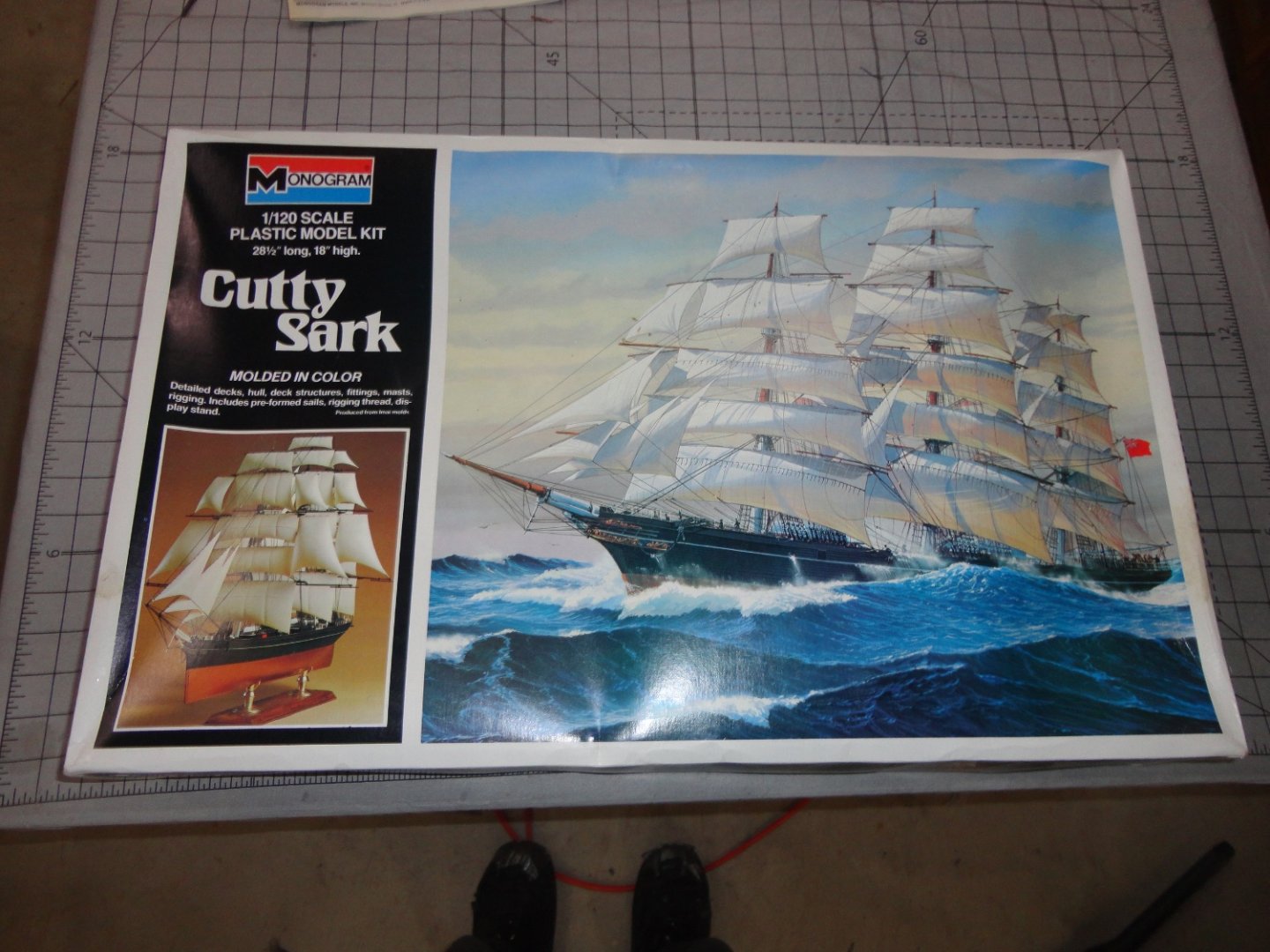
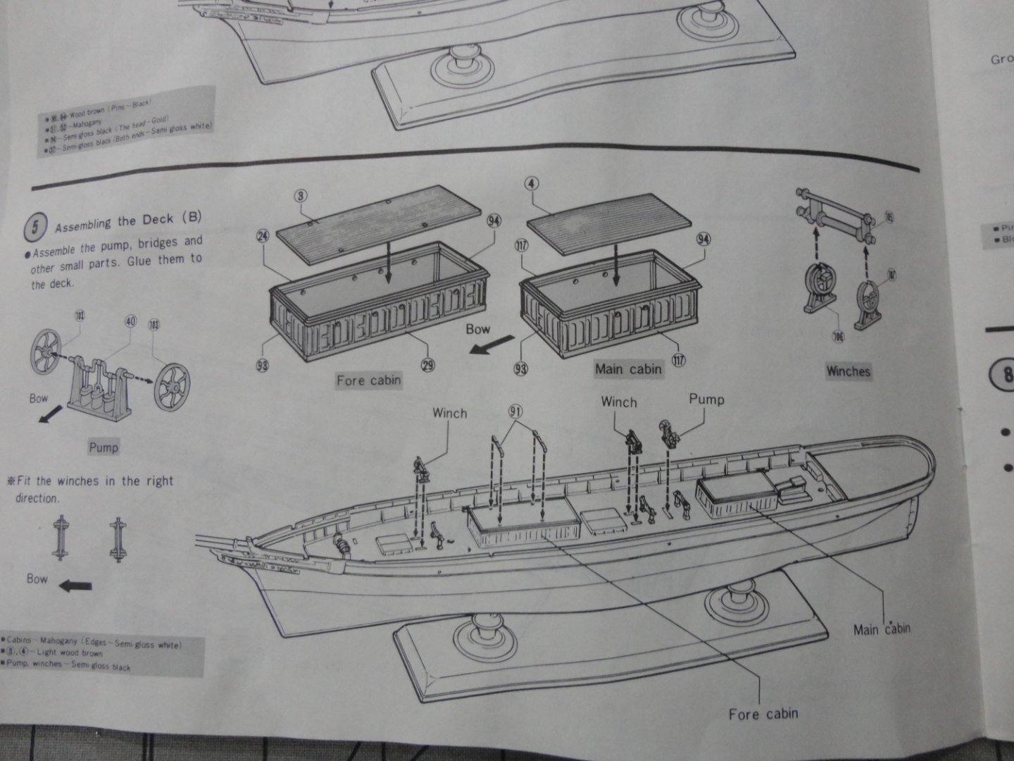
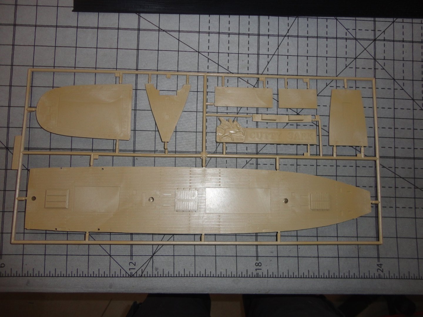
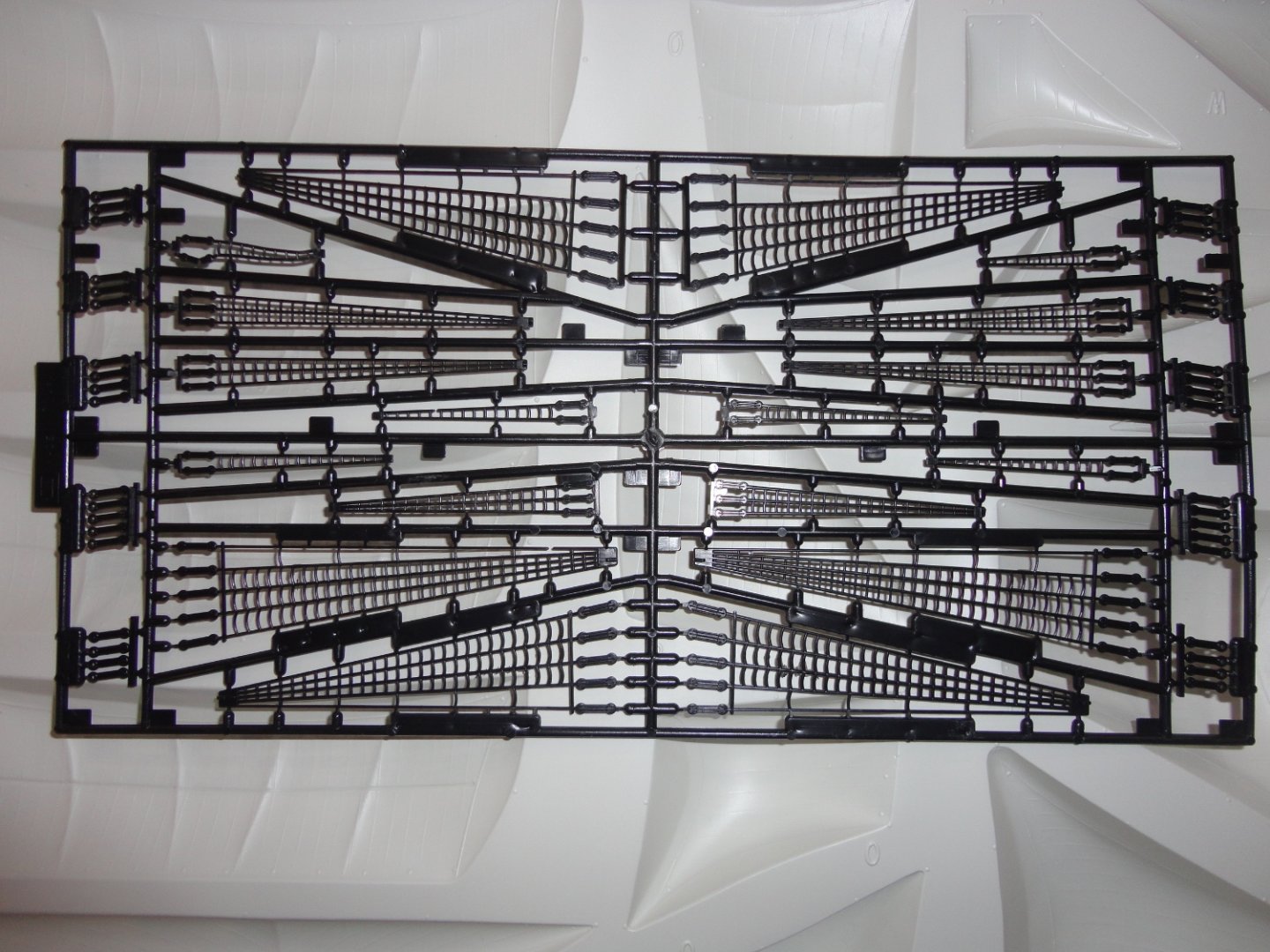
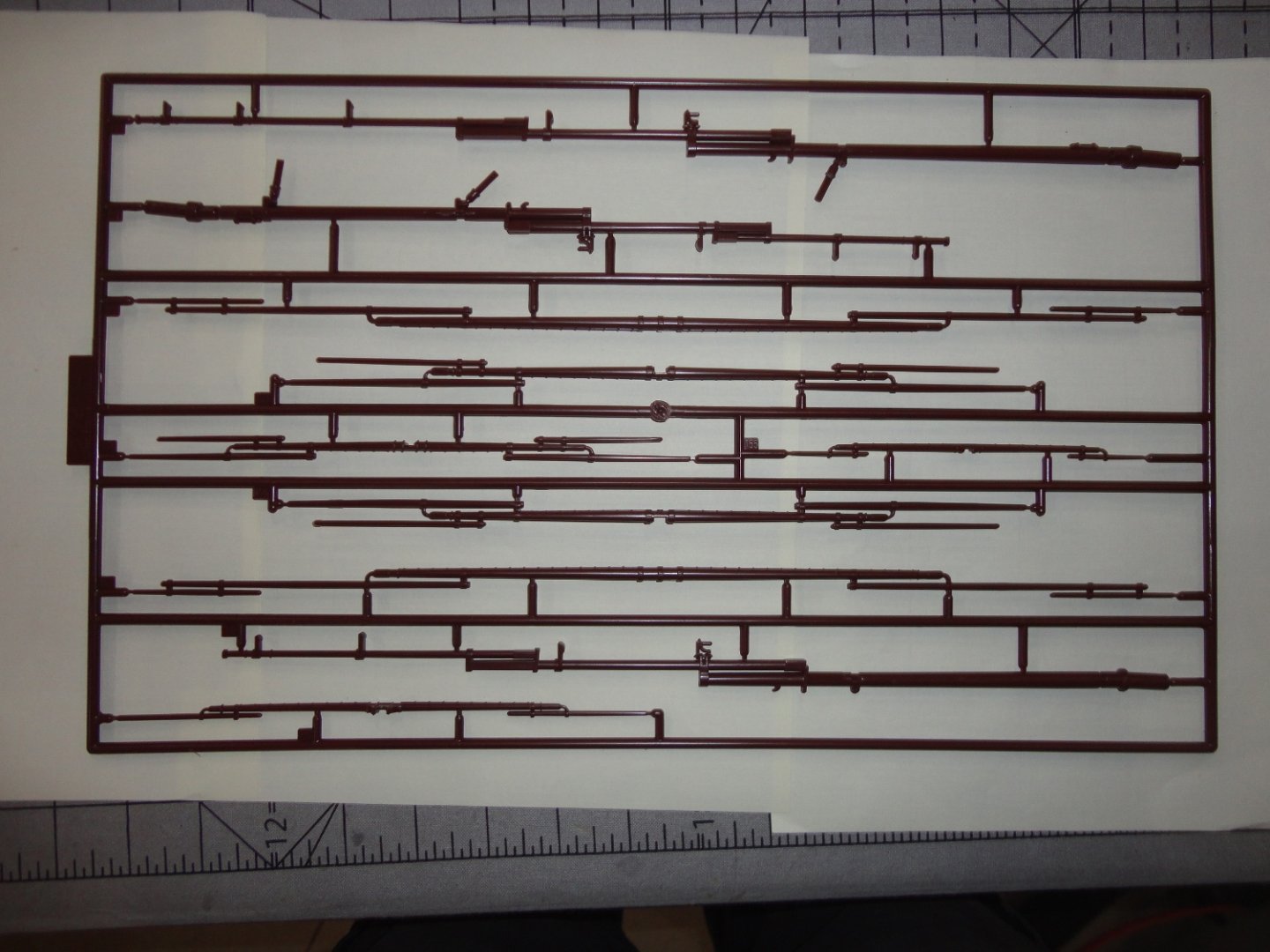
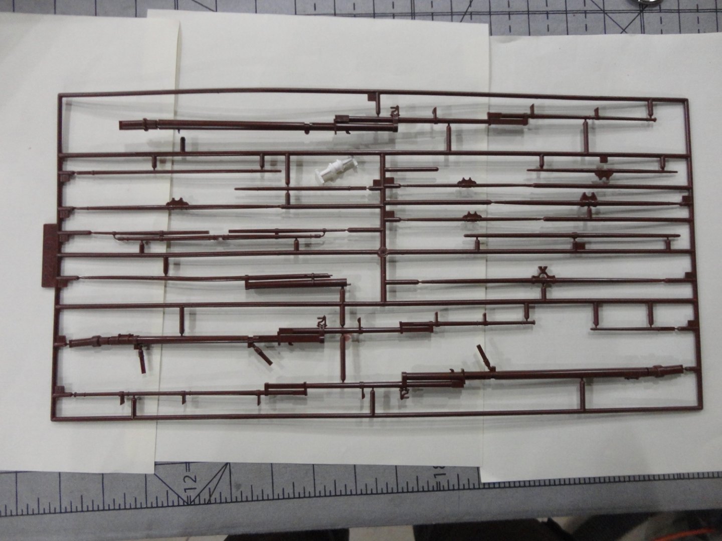
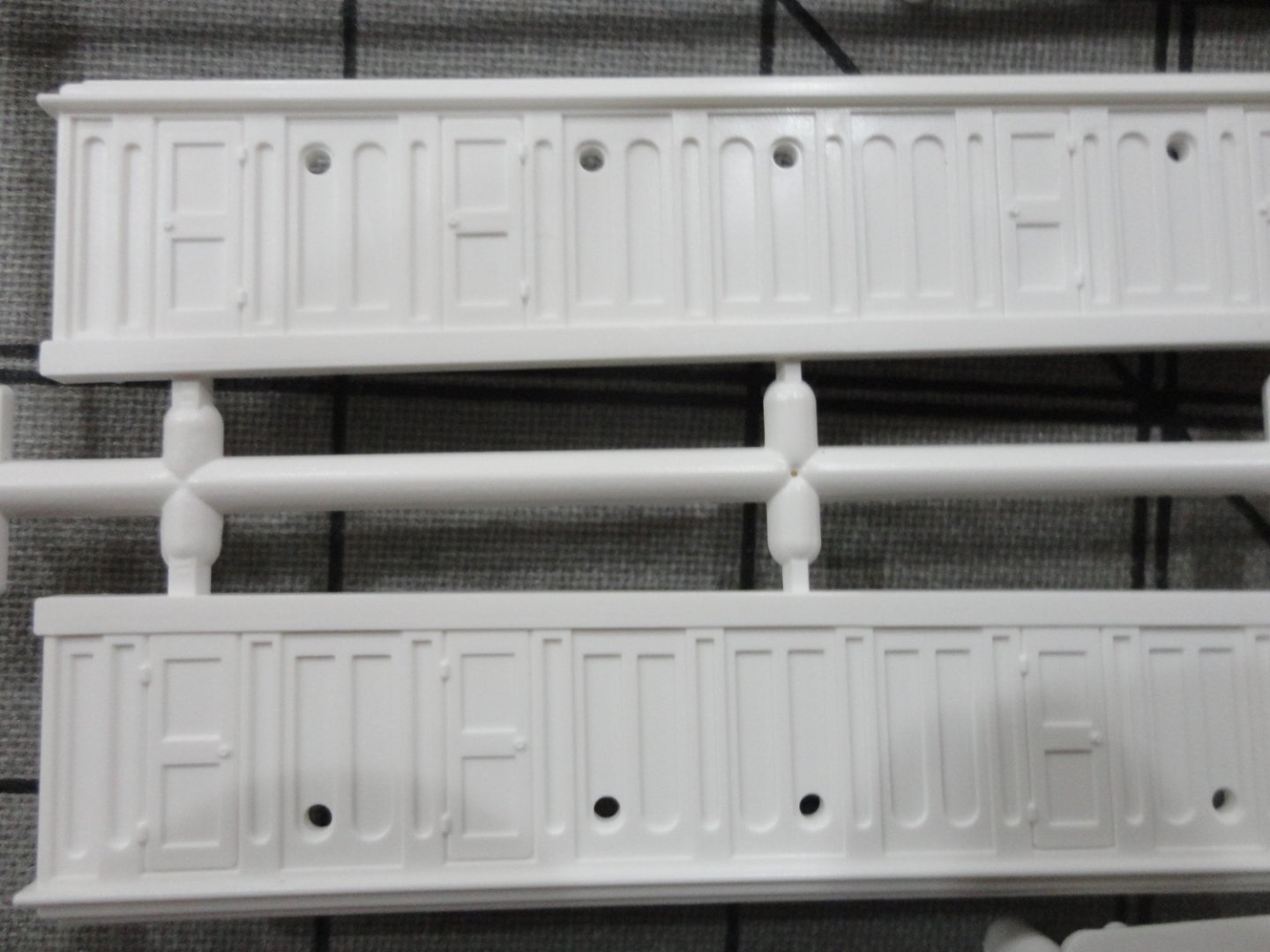
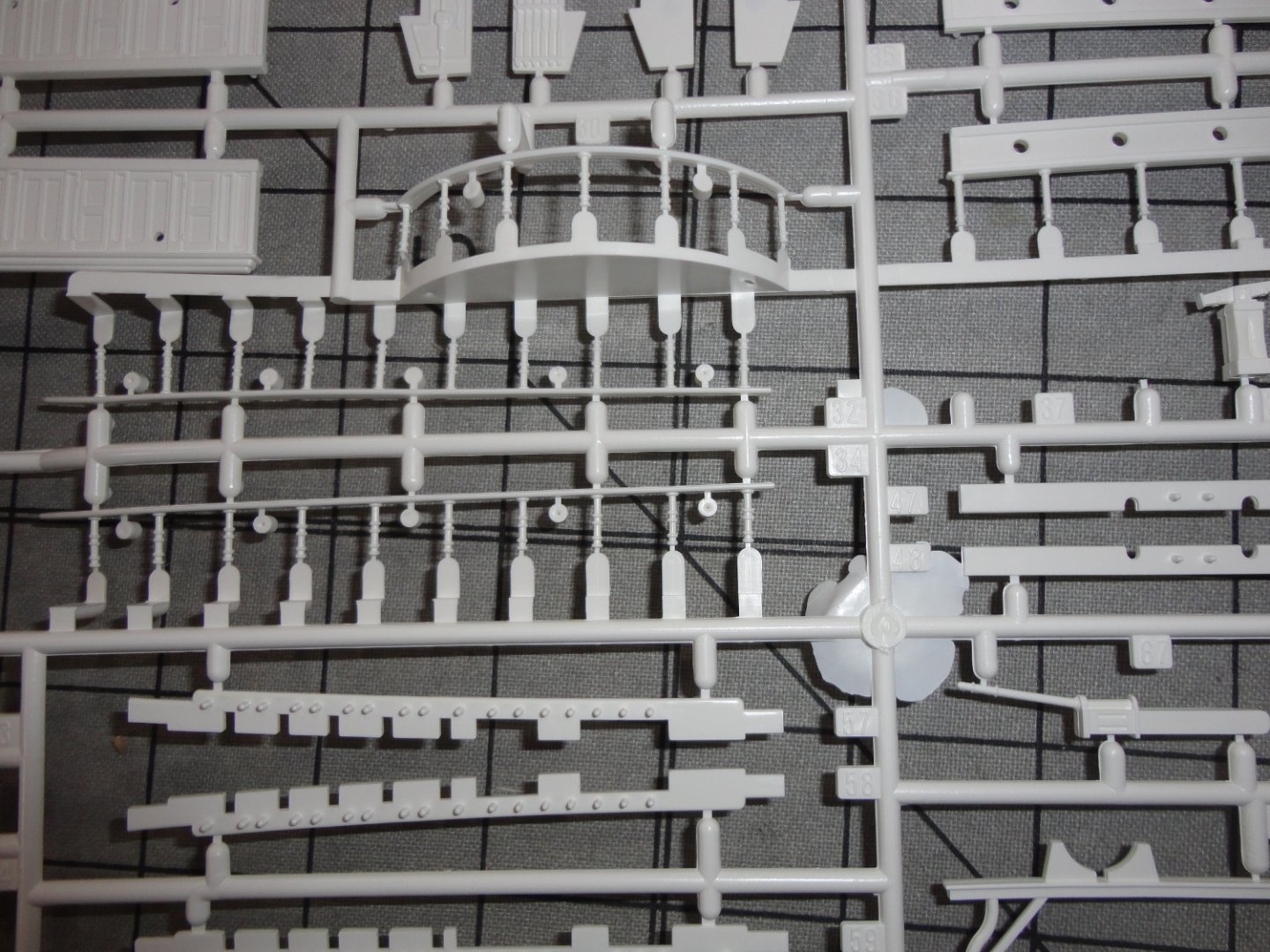
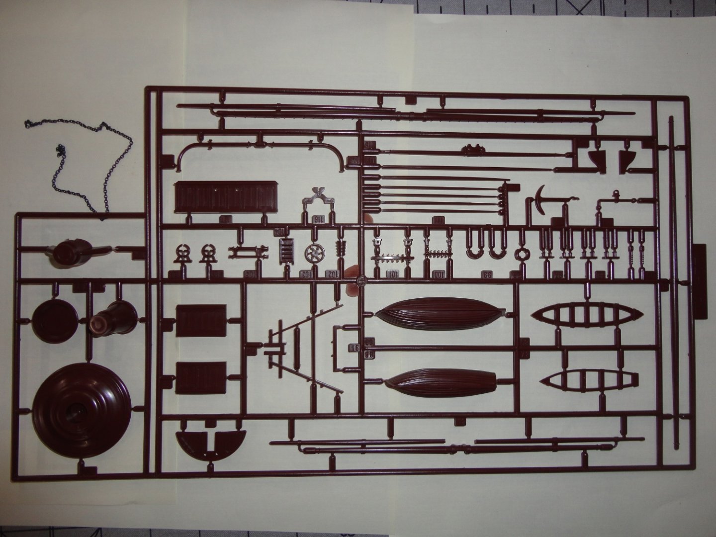
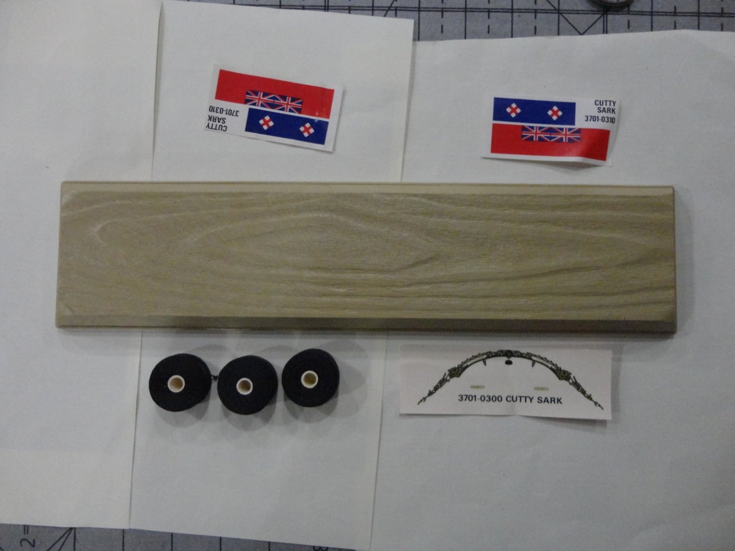
As indicated elsewhere, I sprang for a Monogram release (early 80s?) on 4 color plastic sprues at a true scale of 1:120. I gave up trying to fiddle with a 'so-called' (per the box) 1:130 CS Airfix "Vintage Classics" release (only a few years old) that turns out to 1:168 by Noel Hackney's book on the original kit - having a 15.7" hull and VERY small parts & quite thin yards (among other pieces) made nearly 'rubbery' due to the soft nearly blonde plastic used. There have been comments on softer plastic used in 'later releases' of many kits (originally well-regarded) where aging molds have less definition and more flashing. First and second releases of the Airfix molded in better black plastic come up on Ebay now and then for around $50 (USD) or so, and may be doable for someone with the skill and inclination to accomplish miniature work. Note: other than on the cabin, no stanchions for railings are in the Airfix kit. A 1:150 Academy CS I examined for a while (said to be a 'shrunk down' version of the original IMAI 1:120 CS) was molded in 4 colors and, apart from only having fully extended studding sail booms on the yards (some have cut these and re-glued in a retracted position), it is in my opinion a much better kit (but not large - having about a 16" hull) suitable to encourage a young builder to try the hobby. And thus I gifted that kit to 6th grader who expressed an interest in models. I binned the 1:168 Airfix. Below is the boxtop of the Monogram kit. But I've digressed ... the short history is that Imai of Japan produced a fine 1:120 Cutty Sark plastic model having a 22" hull (compared to the nearly 28" hull of the 1:96 Revell CS or Thermopylae). That makes it halfway in terms of length between the Revell and the Airfix versions. Monogram acquired the molds a some point (others will be more familiar with the history of this kit, as well as the convoluted history that follows ownership of the Airfix molds). Aoshima produced the kit next, followed by a hiatus and then a re-manufacturing period early in the present century. They were considered 'pricy' for a plastic model (and still are, since production was limited compared to other sorts of kits and even the later Aoshima kits are now 'out of stock' according to retailers ... that leaves Ebay - and a few other sites, or the odd model kit collectors' show - as the most likely source for it. I paid $125 plus $15 shipping from New Jersey (UPS truck) to my small town well West of Philadelphia. Having examined the contents I'm pleased with it as a means to get a hull ready without having to stick-build, so I can practice rigging it as well-explained in Hackney's book - which can serve as a decent set of instructions to make up for the cursory sort that came with the kit, mostly valuable for the line drawings of assembly. I figured the Monogram booklet would be in English - which it is, as the Japanese versions are only in ... Japanese. Having built a Woody Joe kit, I got Google translate on a phone - and it did indeed translate (more-or-less) what would otherwise be unintelligible lines of unfamiliar characters. But I think the Hackney book, 'Cutty Sark' ... just one book in the 'Classic Ships - Their History and How to Make Them' series sponsored by Airfix goes well with the 1:120 kit, as most of the modifications and all of the rigging information is applicable. In 1:120 scale, this project is far more practical for a builder not wanting the rigor of a nearly 4 foot long 1:70 wooden kit - nor wanting something nearly as large size of the plastic 1:96 kits (nearly 3 feet from stem to stern). I believe I've found a very good compromise. So let's look at what's in the box. First, some of the instruction booklet. I found 'Made in Japan' on at least one sprue, and the IMAI mark on the underside of the display stand. But one can see able that Monogram identifies the parts as made in the US from unaltered Imai molds. BTW, there are several locations marked on the underside of the stand for the builder to choose where to drill through for the stanchions the hull will sit on. I plan to fashion a wooden base of colored hardwood and turn metal stanchions. The page shown below hints at excellent detail on the cabin sides (and I found this to be true), but also to the most obvious mis-calculation on the design of the hatchway on the weather deck just in front of the poop deck. Others who have modeled this kit advise correcting the goof using sheet styrene - not too hard to do. Also, both winches each have one cable lifter (another mis-interpretation of the Campbell drawings), thus one rom the rear wench must be cut off and applied so that the front winch will have have lifters on both side for the anchor chain. Some reasonably fine chain was included in the kit, but perhaps a longer length would have been better. The next shot depicts fully extended studding sail booms - which I expected would be provided in the kit. But the presence of SIX masts (each molded as a single piece ... might have been nice to 'build them up' like in the Revell kit) had me confused, 2 Foremasts, 2 main masts and 2 mizzens ! Only by looking all the sprue over did I discover that the 7 yards having booms ALSO have them molded with the booms in the retracted position ! This is cool, so the builder can choose which to use. All the other yards are common to either way of building. Below is a picture with the booms in-board ... the sensible way to make the build, since if the booms are fully extended one HAS to put sails on them or the model will look odd. Thin plastic sails are included (quite typical), and I'd only use them as forms to mold lighter material pretreated with watered-down PVA or other stiffener. The decking is molded in tan, and has negative caulk lines between planks. There is no joggling, and the jointing may appear to regular for some - as a more staggered pattern might have been better. But the weather deck is all one piece ... no sectional joints to deal with like in the 1:96 kits. A closer look. I'm pleased with the detail on most of the parts - yet plan on using veneer for decking rather than paint, just one more way to go. A closer look is below. Now the hulls look well formed, but my attempts to get close shots with the lousy camera used didn't turn out. The detail at the bow means no decals are needed there. A decal is included for the stern decoration. Whether is can still be used is uncertain, but I could carefully cut it out and apply to tie a low profile 3D appearance. 'Don't think there is any PE for this kit. The fretwork at the bow is not pierced, but this might still be done. The rudder is molded on. The ratlines are molded (often typical), versus having to weave them one's self as with the Airfix. But the 1:120 scale is large enough to do actual deadeyes (as well as blocks) - even if they go a little out-of-scale. I did not a slight deformity to one upper molded ratline molding - still fixable. There was a slight bending to some of the sprue, but the individual parts look OK. The bowsprit has a slight bend to it - again correctable with care, but I plan on replacing it with a turned piece of wood - since I want to drill through for fore stays. Below is the sprue with the yards having extended studding sail booms - very wide ! Note also the three masts. Some have carped that the top gallant mast sections are a little thicker than they should be. I really don't notice it, and as molded there shouldn't be deflection is the rigging is not overly tight. I note that all the yards (as molded) will be in the raised position, and I intend to have the lower able yards in the lower position (Hackney's "harbor rig"). So the mounting pads for those yards will have to be re-positioned. There were two sub-bags each having two sprues - the parts shown thus far were not in plastic bags. Below is the sprue with the yards having booms NOT extended. Note the loose white piece - a few parts had come off but were in the bag, due to handling over about 40 years. I note that one thin railing stanchion had broken off (but was present), and two others were not fully molded. This is fixable with sprue or styrene - but I might also turn my own railings since I have a Unimat miniature lathe with a universal 3-jaw chuck (it came in handy in the Khufu Barge build). A closer picture of the cabin detaining. Various parts on the white sprue. The boats seemed OK. The tops were not pierced, than can be done with care. To rig more authentically, a builder will have to make lubber holes, but any notion of individual fair leads may be impractical - so those lines can pass through where the slats will be pierced linearly. Below is a closer shot of the boat interior - nicely done, and a little dressing is all thats needed. A closeup of a top. The molded deadeyes/ratlines would glue in the depressions - but for rigging with actual deadeyes or beads, the voids must be filled in, the slats pierced and holes drilled for the deadeye fastenings as needed - all optional, of course. A plastic base is included with some 'average' rigging rope (I won't use), a decal and paper flags. Below is the Imai mark molded on the underside of the base. For hull comparison (to the Imai hulls show much further up in this post), I show the Revell 1:96 Thermopylae - another 'keeper' of mine that I really want to do 'justice' to by 'busting' where needed to get closer to the ship its supposed to be. Its a pretty big model as plastic models go, so starting with the 1:120 CS version (as I said - mainly to try out rigging ... also to become reacquainted with plastic modeling and painting) may be a good experience without loosing my eyesight (or patience) with anything smaller. My opinion is that the Imai/Mongram/Aoshima kits are reasonably well thought out (with only a couple of corrections needed), well molded with good detail, and can be made into a much better model than simply building 'out of the box'. Some scoff at the price examples have gone for ($125 - $165), but the supply is limited and shrinking all the time. You can't 'take it with you', mate. So if this floats your boat, go for it ! Fair weather ! Johnny


-
Thanks, Shipman ! More news - today the Monogram issue of the 1:120 CS (first made by Imai) arrived. A few Imai and Aoshima issues were also seen on Ebay, but I went for the Monogram because I figured there would be English instructions - versus the Japanese only one the other issues ... and my hunch proved correct ! Also it was the lowest price - about $125 plus $15 UPS from New Jersey to my small town well West of Philadelphia (by no means a suburb, as farms are nearby ... but 'civilization' is slowly creeping as we are on the road to Reading PA). 'Seems a little steep for a plastic kit, (as much or more than one can come by a Revell 1:96 CS or Thermie) but ... my opinion (as expanded below) is that it it worthwhile. With anticipation I examined the box with the original cellophane wrapping almost completely intact - the seller did picture a small slit on one side of the plastic, but it did not go to the corners - so the contents were as manufactured and sold. The cellophane was removed and the box opened, and I had to do a few double takes at the contents - some sprues were in their own thin but sealed plastic bags, and some not. At last I figured it out by both counting masts and yards PLUS looking through the instruction booklet. BTW - the instructions are mostly line drawings with cursory text, and there is almost no advice on rigging. So if someone gets a version with Japanese text, they are not missing much - its easy to see whats going on from the pictures and the Japanese use arabic numerals anyway. The woody Joe Khufu barge kit I built had a LOT more text and other stuff, so I got a Google translate Ap for my 'somewhat smart' Tracphone used only occasionally - and I could translate almost all of the Japanese into English. In light of the above, Noel Hackney's book on building the Airfix CS will be VERY useful for building this (or any reasonably sized CS kit). Noel did a fantastic job explaining certain details on modifying the kit before diving into construction, and this 1:120 kits can use many of them. Of course, one has to do a bit of cross referencing to get through the book - but in the process I've learned a great deal. I note that in terms of hull length, this 1:120 kit is halfway between the 1:168 Airfix and the 1:96 Revell. The Monogram kit has about a 22" hull not counting all of the keel projecting forward of the hull. The quality of the tooling and molding is excellent. I note that the deck has negative space between the planks instead of positive caulking as some other kits have (no joggling, though). The masts and spars have some springiness to them - but not too much. That means that they are not too rigid either, so should not be subject to stress breakage. Counting SIX masts threw me at first ... yes - 2 fore, 2 main and 2 mizzen masts (the three mast sections of each are molded together as a unit). Some of the yards had studding sail booms extended, and some did not. Then I saw the model built EITHER way in the instruction booklet - one version with extended booms and one where they are retracted. So I counted ALL the yards and realized that one sprue has the three masts PLUS seven yards with extended booms - and this sprue was not in a plastic bag. Other bagged sprues have the masts and all the spars with retracted booms (plus the yards with no booms that are common to both versions) ! The kit is molded in 4 colors (like the 1:150 Academy CS ... but THAT kit only has extended booms - which forces one to either have it in full sail with studding sails, or having to cut-off and remount the booms inboard on the yards). 'Haven't looked on all sprues, but one said "Made in Japan". Yet the booklet stares in BOLD type, "Plastic parts in this kit are molded in the United States from IMAI molds without any modifications". The deadeyes/ratlines are molded, but doing them properly with actual deadeyes and thread seems doable at 1:120 scale. The beads proposed for a possible build at 1:168 (oversized for the small scale, and I've given up on it anyway) are pretty close at 1:120. Thin molded plastic sails are in the kit (typical for several kits) - I'd never use them, but they could be forms for much thinner material treated with thinned water-based glue. For 'harbor rig', they aren't needed at all. A couple parts were off their sprue from whatever handling occurred in at least 40 years of existence - and this is not uncommon for plastic kits in general. A couple railing stanchions were not fully 'filled out', and one was broken off but in the box. One of the topgallant mast molded ratlines is a bit deformed, but bendable and likely re-formable ... that is, if one wanted to use the provided molded ratlines. No blocks were ever molded, but I saw one report of an early Imai kit that had some blocks bagged inside the kit. My guess is that they may have thrown some plastic blocks in the first release, but economized soon thereafter ... and they were probably out-of-scale. What I'll have to do is take pictures and put a "kit review" together in the kit review section of the forum. It would likely apply to any version of this kit, since the same molds were used by all. I note that there are reports that late-issue Aoshima kits have more flexible yards due to softer plastic ... just saying. Fair sailing ! Johnny
-
You've cracked the case. Per Occam's Razor, most often the simplest explanation is the right one.
-
Ahoy Shipman and 72Nova ... The text from a much larger history of Airfix was 'quoted' as a 'review' (I didn't write any of it myself, and wanted to respect the originator by only reproducing a small portion in our forum in the spirit of 'fair use' - for informational purposes only), and a specific sub-list of 'large' Airfix ships (per our scope of interest) was also pasted 'as is' - warts and all. This info was found by repeated 'googling' (e.g. Airfix collectors, Airfix model shows, etc.) until stumbled upon - in that there seem to be Airfix collectors, and an EXTENSIVE list of every model ever produced by that manufacturer can be thus viewed by the public. You are quite right (my oversight) that Hackney specifies the issue scale of the CS as 1:168, and certainly the original effort at details such as 'pierced' fretwork at the bow, sub-miniature molding of CS scroll work at the bow (and a 3-piece sections inserted in the stern with 3D scrollwork, so no decals were needed), deadeye groups for the pin rail that have chainplate going through the rail and down at an angle to the water way - as well as separate mast segments, tops, caps & cross trees for assembly (permitting shroud loops at the option of the builder as the masts and yards are built in the order that a real ship was built per Hackney's book) was a masterful work of mold-making 'back in the day'. The state of my eyes and less-than-nimble fingers made dealing with the shortcomings of the 'Vintage Classics' version overly daunting. I imagined that bonding spring wire to the tops of the yards (after replacing the top and topgallant mast sections with relatively firm wood) would limit selection of the yards - and would be completely disguised by having a little folded material grommeted on top of the yard to represent furled sails. Once I've learned more (and other obtain an original issue kit or get a good buy on a PAIR of latter-day kits - to assure the likelihood of 'one good kit' in terms of non-deformed, fully-molded components) I might be tempted to try it someday ... I've no idea what the codes on the right hand side represent, and presumed them to be meaningful only to diehard kit collectors. As a former train collector (Marx 3/16 'scale' freight cars that ride on O-gauge track), I realize just how far 'into the weeds' as collector of anything can go. If it exists, there seem to be collectors of it. I sold-off my train stuff a while back - as well as a bunch of astronomy gear and also U.S. Civil War small arms used for live-fire in the N-SSA (North-South Skirmish Association) ... can't hang onto everything. Airfix seems to have dabbled in a bunch of different "actual" scales (moldmakers' whims ?), as opposed to doing them all in, say, 1:144. I see the 'ladder' now with how English (and American) scales bear a relationship - twice 1:24 and you have 1:48. Twice that and you have 1:96. Add 24 more and you have 1:120. 24 more and you have 1:144. So 1:120 would (sizewise, as volume is a different calculation) would be right between a 1:96 CS and a 1:144 version (if that existed). Well, for the hell of of it, I found a 1:120 Monogram CS on Ebay (U.S. 'branding', so maybe there will be English instructions versus the Japanese found with Imai or Aoshima releases of the same components). The flat black beads for blocks will be just about right in that scale. We'll see ... Fair sailing, mates ! Johnny
-
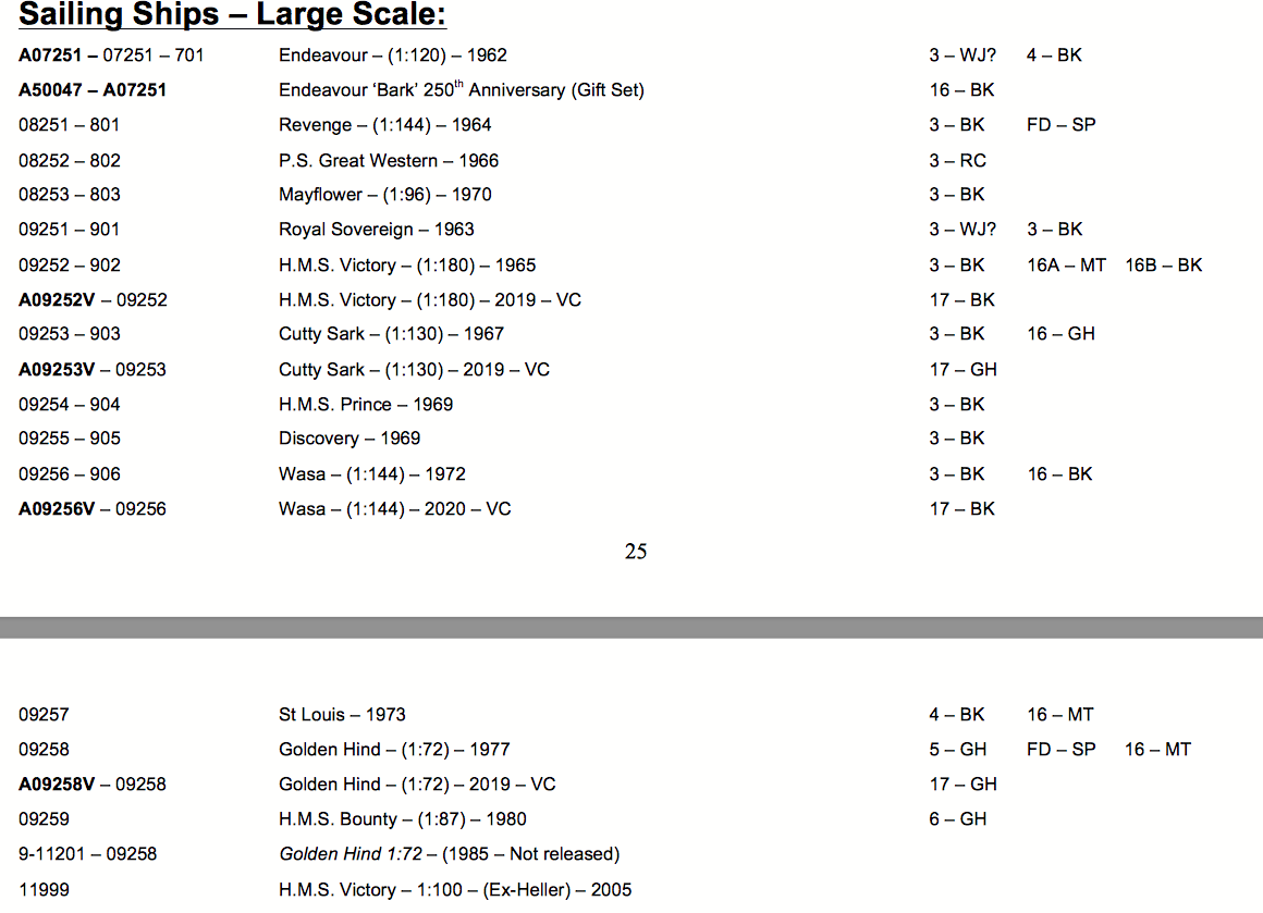
'Did some digging into Airfix history, and there are collectors of kits. Yup, just the unbuilt kits - and they go by the box numbers of the release. That goes for all sorts of kits - but we're interested in ships on this forum. An excerpt from a history indicates that many molds had to be remade at a certain point in the many sales of the Airfoil name: By 1981, Airfix had released over 800 models ranging from aircraft to dinosaurs and claimed to have, “The Largest Range of Construction Kits in the World”! In January 1981, however, the Airfix Company called in the Receiver largely caused by problems at its Meccano subsidiary and most of the toy divisions were closed for good. The kit division along with Airfix Model Railways (GMR) and, ironically, Meccano and Dinky were purchased by General Mills a U.S. company, and placed under its U.K. subsidiary, Palitoy. Production of Airfix products was transferred to General Mills’ Miro-Meccano factory in Calais. It was owned by General Mills under the Palitoy label until 1985 when General Mills closed its U.K. operation when it withdrew from the European toy market and was put up for sale again. It was then purchased by Humbrol, the model paint manufacturer in 1986. Humbrol was based at Marfleet in Hull but production was transferred to the Heller factory in Trun, France, because Humbrol had recently purchased Heller. In 2006, Humbrol got into difficulties, when the Heller subsidiary, which had been bought out by its management, closed and Humbrol was unable to access its Airfix moulds. Humbrol and Airfix were purchased by the present owner, Hornby Hobbies Ltd, based then in Margate, Kent. Since then there has been a renaissance at Airfix with new tools being produced at a rate not seen since the 1950s-1970s with kits like the magnificent 1:24 Mosquito being modelled, and in 2014 we had an incredibly detailed 1:24 kit of the Hawker Typhoon being moulded. Many ‘tired’ old kits, like the Defiant, have recently been replaced by new ‘state of the art’ models and many new subjects added to the range, such as the Whitley and Shackleton. Recently, Hornby sold the Margate site and moved to a new Headquarters at Sandwich, Kent, with stock being held at Hersden near Canterbury. Most production is carried out in India, but some models, including the Quick Build range are moulded in the U.K. Financial difficulties experienced by Hornby following the move resulted in a culling of the kit range. However, in May 2018, Airfix announced it is to bring back many of the older pre-Hornby models in a new range entitled “Vintage Classics”. The models will appear in the new Type 17 box top and will bear their old box illustrations with the year of original release being shown on the box, ensuring that modellers realise that it a ‘legacy’ kit. The company moved back into its old Margate site in early 2019, alongside the Hornby Visitor Centre which had remained there. The original CS nominal (1:130) of 1967 had a box number 09253-903, and the Wasa of 1972 (1:144 - likely the actual scale of their CS as well) was kit# 09256-906 per the pasted section of the relevant kit list of Airfix sailing ships characterized as "large". If one wishes to hunt down any of the 'good' original issues, perhaps finding out where there might by a collectors' show of Airfix or similar items might be of some uses. Lots of luck.
-
You are Soooo right on the poor plastic (pale tan) used on the so-called Airfix "Vintage Classic" 1:145-150 (claimed to be 1:130 on the box) Cutty Sark. The thin upper mast sections and the yards ben almost like rubber ! 'Can't see how they an be rigged without deformation. And I suspect that not all the molds are the original ones as well. Hackney's modification of the tops to make lubber holes and fairleads do not agree with the pieces in the example I acquired to 'see for myself' just 'what's in the box' being sold today. The spindly top and topgallant masts are WAY smaller than the holes in the caps, making assembly problematic unless one fabricates time replacement caps - as well as make wood or metal upper mast sections to both fit properly AND avoid the deflection problem. The yards have to be re-made as well due to the bendy nature. And a fair number of parts are deformed or not fully molded, with flash present as well in many areas - so the mold was run 'hot' and some of the sprues were therefore soft upon ejection and subject to deformation. Also, photos of the model in the Hackney book show the fore and aft guardrails - that are not in the latter-day reissue. If one can find a genuine 'original issue' kit in much better black plastic, I suppose it might be worth building, but I simply 'binned' the above described re-issue as not being worth the time and effort to correct all the deficiencies.
-
'Just gave up on the "Vintage Classic" edition of the Airfix Cutty Sark 'nominally' 1:130 BUT the true scale is about 1:150 ... somewhere between 1:145 and 1:150 depending on how one figures it. First off - the plastic used is lousy and bends terribly. Just trying to get the foremast components together proved that the parts are just not made right. The topmast and topgallant mast sections are way smaller than the holes in the caps, trestle and top - just no way to get any semblance of fit without remaking all the parts above the first mast section from scratch. In frustration, it went out with the trash. Many parts had flash, or were not filled and also misshapen by poor handling after molding OR the mold rate was too fast so the parts were too hot coming out. Way too many problems, so it makes me wonder if the latter day production was even made from the same molds ... In short, I consider it unbuildable without investing WAY too much time for a difficult scale to do with finesse - and not even suitable for a young builder. 'Makes me wonder how half the stuff in the Hackney book could even have been done on an 'original' Airfix English-made example. Yet I note that the same book can be a GREAT learning tool for the Revell 1:96 models (or many other clippers) as far as rigging goes. This makes the second kit I've binned at 1:150 scale - the first being the Academy CS, supposedly a 'shrunk down' version of the Imai/Monogram/ Aoshima (all versions from the same molds) 1:120 CS, which is well-regarded by those who parted with the $130 - $160 (US) for what is considered to be a 'rare' kit (which it is). The Academy 1:150 is molded in 4 colors and is at least buildable, and might be suitable for a youngster wanting to give ship modeling a try. I note that all the studding sail booms were molded fully extended (just as with the 1:120 version), a very limiting choice on the part of the designers - and most builders cut them for moving to the retracted position (or discard for depicting her in the 'wool trade' years when the studding booms would have been stored below. 'Don't know how you've managed, mate, with the Great Harry at 1:200. My hat's off on what you've done ... perhaps enough to attain Jedi mastery of the miniature !
- 740 replies
-
- 5
-
-

-
- Tudor
- restoration
- (and 4 more)
-
Since its too late to have a filler block in that 'deadly' gap between the fist frame and the keel (you have too many first planks in place to go back), there is another approach you might try. It involves pushing so-called wood putty down into the void and pack it in good with a dowel so that the putty completely fills the void and even 'bloops' or oozes out of the gaps in the planking. You can also use a common product found in hardware stores known as 'plastic wood'. To help limit the amount of oozing, you cam apply blue 'painters tape' to the exterior to hold back the product bing packed inside. Then allow plenty of time for a hard cure. Removing the painters tape part way during the cure (the outside hardens first) will allow you to scrape away some excess on the outside. Since there is some gapping in the planks between the first and second bulkhead, you might fill that void too. Once cured, you can continue planking. Then when sanding down to fair the hull prior to the second planking - done with thinner wood that will conform more easily to the hull shape - even if you sand completely through one or more planks in places, there will be a substrate in place and not a void. Just a thought.