Snug Harbor Johnny
-
Posts
1,501 -
Joined
-
Last visited
Content Type
Profiles
Forums
Gallery
Events
Everything posted by Snug Harbor Johnny
-
I have a an old Unimat miniature lathe. Since its powered by a Dremel type motor, it is underpowered for metal turning, but with light cuts it does OK on brass or aluminum stock (relatively small in diameter). Steel is tough on it, but wood cuts 'like butter'. For our purposes, the most useful accessory is a 3-jaw 'Universal' chuck ... that is, one that operates with all three jaws closing simultaneously so that round stock is automatically 'centered'. One can then 'spot drill' the end on center (after facing-off the end), followed by drilling (sometimes in steps, depending on stock size). Since the Unimat is so small, the largest dowel stock that can pass through the head is around 1/4" - suitable for most yards and a good many mast sections - but not all, depending on scale. You can see how I used my lathe in the Khufu build (see at the bottom of my post) doing a whole bunch of palm-head supports for the canopy. A somewhat larger and more powerful lathe (that can also take thicker rods) would be preferable ... but only up to a point - we're doing modeling, not machine shop jobbing. The second accessory to get is a 'live center' with drill chuck for the tail stock. This will permit support on the end of round stock so you can have a greater length extended from the head stock. This is limited by the diameter of the material (and the type of material), and the depth of cut - so that deflection is limited. What I've had to do is work on short extensions of stock (due to deflection and the lack of a live center), then advance the stock to work further down on the piece. Drilling with the tail stock is done with an ordinary drill bit chuck that screws on the threaded portion of the tail stock - and is not 'live' (so the drill bit will not rotate). Some time ago, a four-jaw 'independent' chuck was obtained for square and odd sized workpieces - and I was able to do round work by centering a piece of round stock 'reasonable well' (as large as 2" in diameter) within the steps of the jaws (when reversed), THEN truing-up the diameter by cutting the periphery after face-off. Boring was done with a small bar after drilling. A "T" groove table mounted to the cross bar permitted a tool mount to be more easily manipulated and angled than an ordinary tool holder. These ideas should get you off to a good start.
-
 Some say that Domenico Scarlatti was the most prolific composer for the harpsichord, having written over 500 sonatas. Others say that he was the most PERSISTENT composer, having written a harpsichord sonata over 500 times. This may also apply to doing ratlines ...
- 740 replies
-
- 4
-

-
- Tudor
- restoration
- (and 4 more)
-
OUTSTANDING method, mate ... and VERY well shown pictorially ! It is step-by-step and easy to understand what you did. This will definitely influence me on a future build, so I'll be sure to watch further developments on your build. This is effectively 'caul bending' (or veneering), in which several thin pieces are formed around a bending caul (I may have the spelling wrong) after some glue is put between the elements to be formed. I did exactly this when building a bent-side Spinet Harpsichord (a large project). The side of the instrument's 'bent side' meant that I only needed a curved piece to bend against, and used a number of wood blocks held by clamps to keep the outside of the work-piece itself against the form (that had a small amount of 'spring back' allowance due to the 1/4" or 6.35mm thickness of the components). You have made a nifty jig to allow the exterior clamps to hold the bent pieces together while the glue dries, due to the small size of your application. The thinness of your component pieces means that there is little need to worry about spring-back. The method you show may take planning and jig design, but it is WAY better than drafting outlines on plank stock, then jig sawing frames out. Hand sawing frames makes for too much variation that is hard to sand to uniformity and still have them symmetrical. dealing with the grain of the wood can also be a challenge ... thin ribs are prone to breakage at the weak spots, and end-grain in places on the edges makes fairing and planking more difficult. By forming frames as demonstrated, there is great strength all along each rib. Once all the ribs are in place, a stable planking jig exists. Once planked, the attachment points along the sides are released and the ends can be trimmed where they should be. Fair sailing ! Johnny
- 12 replies
-
- 3
-
-
- Armed Longboat
- Ancre
- (and 1 more)
-
'Just LOVE how your hull is coming along ! There are some similarities to the Khufu barge, in that there are 'stringers' spaced on the interior, and the bottom is nearly flat - giving the craft greater stability (in NO ways canoe-like) yet able to move across shallow waters.
-
Thanks for the tip, George. 'Just ordered some in that size plus the next up from that ... they'll come in handy whenever the clipper project get underway. Right now, I'm focusing on finishing the current build - which has waited too long for completion. Yet the long delay has made current information and scholarship available, much to my advantage.
-
Perhaps some 'plastic wood' filler might 'fill-out' the bow area. Instead of the wood grate stock as railings, pins stanchions with thread (or very thin wire) may be better. Beads for dead eyes might do. Think 'out og the box'.
-
How did you make (or source) the tiny jackstay eyebolts? They seem a real challenge at 1:96.
-
I saw Artesania Latina's 1805 Swift with a 'buy it now' price of $49.99. The AL Bounty Jolly Boat was for $42 and change. These look like great beginner kits that don't cost much ... and I know there is at least one build log for the Jolly Boat. Check it out.
-
Ahh, lacing the deadeyes ... With the CS the lower ones are inboard and below the gunwale. Many other ships have presious little room between lower deadeyes on the channel and the hull. This makes me thin k that I might try 'rough lacing an upper deadeye to a lower one BEFORE mounting the lower deadeye on the channel. Just as cannon tackle have the free end on the line wrapped around the sheaved lines between the blocks to keep them neat, I plan to do the same with the free end of the deadeye lacing line before mounting the lower deadeye to the channel. A shroud with a loop seized on one end goes through the lubber hole and over whatever mast section to braced, then the free end will be put around the upper deadeye , snugged and tied so it can still be adjusted. Then the lacing line can be adjusted (taking up shroud line as needed on the upper deadeye) until the desired position of the upper deadeye is achieved. Then proper seizing is done for that shroud around its upper deadeye. The other side's 1st shroud is done concurrently to the above. The (in pairs) the other shrouds are done in turn, and the upper deadeyes should all be fairly parallel to the gunwale at whatever height chosen.
- 248 replies
-
- 2
-

-
-
- Cutty Sark
- Revell
- (and 2 more)
-
I knocked over a container of the tiny brads and thought I'd have a time picking them all up. Then I remembered a handy 'magnet on a stick' the Admiral has, that looks something like a golf club. 'Worked like a charm, since the brads (and a few other bits) are magnetic. Too bad there's not a 'magnet' for brass. BTW, I found that quick set epoxy ('5 minute' type) does NOT stick to the silicone mold, and that parts cast in epoxy have a 'flexing state' after 15 minutes, so perhaps the curved figures for the cupola roofs can be modeled and cast flat - then formed during the 'flex stage'. After much more time than that (30 -40 minutes) the pieces are firm - hmmm ... about the time a blue pill takes to work. 'Full cure' is 3 - 4 hours, but I like to let them sit overnight before sanding/filing for any clean-up. I didn't find 'casting resin' at Hobby Lobby - they have discontinued sales. I asked why and the answer was 'defective product'. I believe that there were too many people who did not mix EQUAL parts and did not get proper curing - thus returned product for a refund as 'defective'. The manufacturer provided no warranty due to lack of control of product use, and also had a 'litany' of hazard warnings because of component chemicals ... again, we have ultra cautiousness these days over ANY potential liability. Yet these hobby 'resins' are just epoxy that color is added to, with varying cure times. Two aisles over they sold bottlers of epoxy glue with varying cure times as well ... go figure. BTW, if the Admiral's in a mood and sounds 'beat to quarters', this gunner can chew the pill (tastes bitter), chase with water on an empty stomach and be ready for action in 15 minutes ... aye-aye Sir !

-
'Saw a clear demo on the 'sew' method for ratlines (it may have been part of the USS Tennessee log 1:96 scale), The shrouds/deadeyes are done first, of course (and some save the ratlines for last to make other rigging easier). A sewing needle is used to pull ratline thread through the shrouds (with paper marked for horizontal ratline spacing fastened with clips behind the shrouds) from whichever side one is comfortable starting with (RH vs LH). Then everything is adjusted, and after all ratlines are in place and tweaked, a tiny bit of one's glue of choice fixes all the joints (thinned PVA vs CA), with the very ends clipped close with flush cutters.
- 248 replies
-
- 1
-
-
- Cutty Sark
- Revell
- (and 2 more)
-
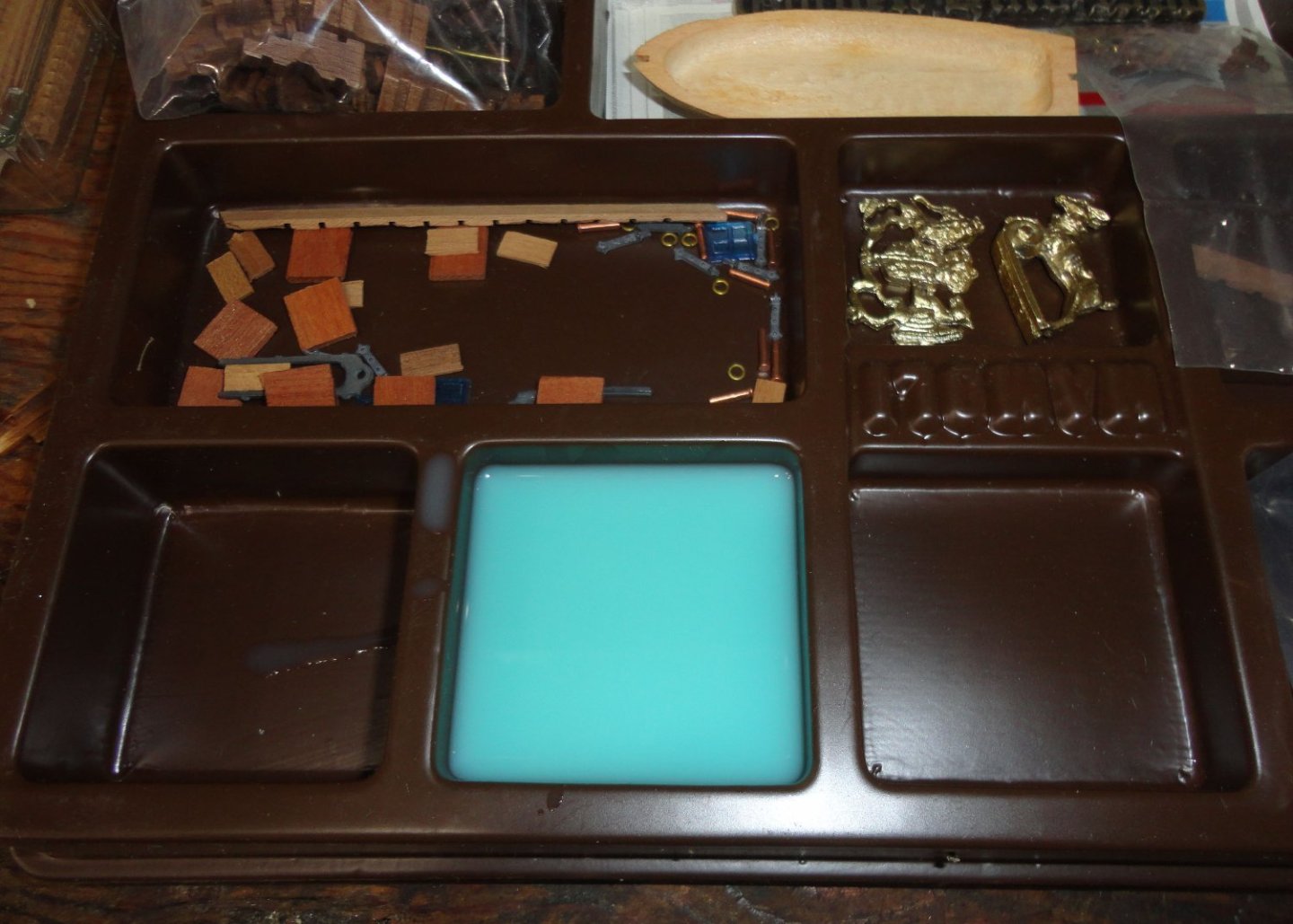
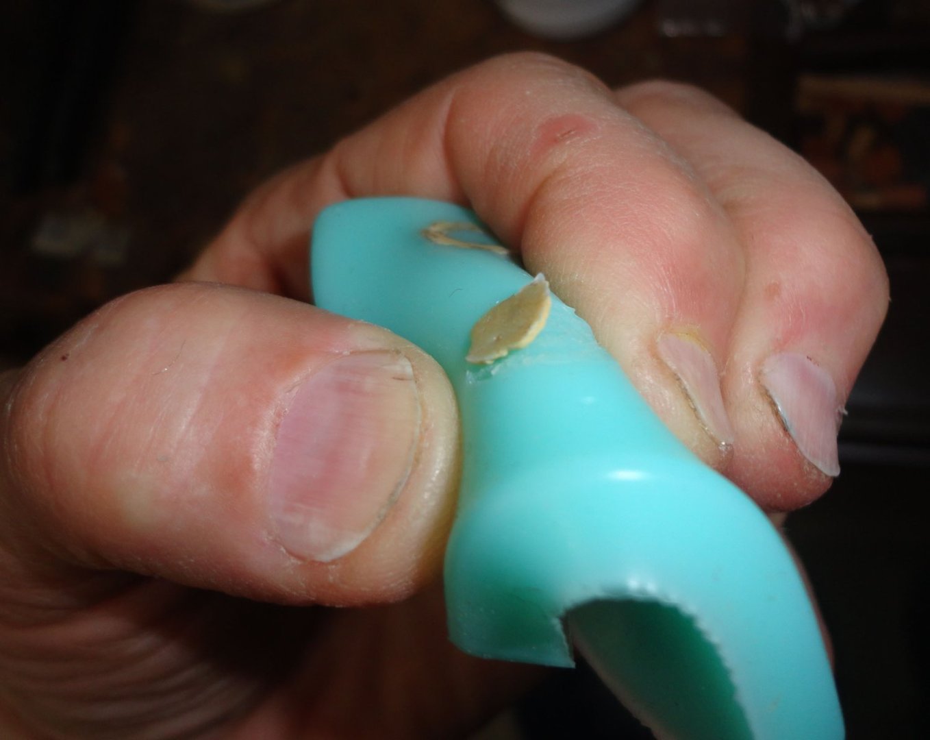
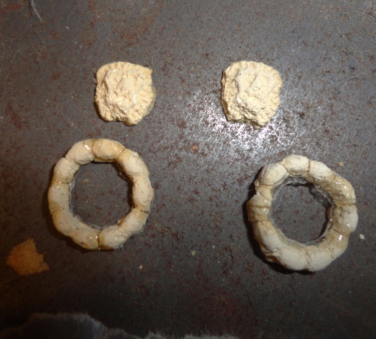
'Realized that I need a few more tiny lion heads and round gunport surrounds - and the old latex molds crumbled with age. Not finding liquid latex locally - and it is a long process to 'build up' layers thick enough to use as a mold, I ordered 2-part silicone mold material on-line and found a new mold easy to make. I place intact original parts (molded form dental "stone") in a plastic compartment from a Mamoli kit ... any convenient container thats not too deep will do - or even a flat glass or plastic surface that one put a cookie cutter over as a 'dam'. Traces of gold paint are on the pieces to copy. The silicone material is two-part, and at room temperature has a 30 minute working life. The key to successful curing is getting EXACT amounts of part A & B together, and the best way is to weigh it out - I'm using a small cut-down plastic cup 'tared' (zeroed) on a small digital scale. I watched the stiff 'de-bubble' itself after 3 minutes of mixing with a stick - and allowed 15 minutes for this process to occur. A stick was used to drizzle silicone carefully on the items so as not to have bubbles. 'Should have used a little 'Stick-um' on the backs so they would not shift, causing a thin film of silicone to get behind them - later trimmed away with nippers. After 3 hours curing the edges were teased up[ with a dental tool, and there was no sticking to the surround. The cured mold was 'squeezable' to pop out the originals. And a nice mold was made ... with a few specs of gold left behind that were easy to remove by squeezing the mold and wiping with a damp cloth. Now the Durham's water putty I tried did not cast as nice as dental 'stone' ... not so hard and more brittle, whereas 'stone' is made to be worked on in a dental lab. I tried less water and added a little Elmer's glue to the Durham powder, and that worked better. What I'll get today is was is MEANT to be used with silicone molds - resin. This is available in hobby stores and referred to as 'casting resin'. Below are the initial pieces made - the gun port rings had to be Ca'd together as they broke on de-molding. Casting resin will be much tougher. As far as the ship goes, I realized that the angles of the sides astern were a bit too far off, so trimmed them into a better profile - nat quite right, but what I'll have to live with on my attempt to make a 'sow's ear into a silk purse' ... if not silk, then perhaps linen. The drilled channel were CA'd on the starboard side. Of course there's lots more to do.


-
Actually ... there is a little 'real' (Honduran) mahogany available by the piece in specialty wood craft stores (those that are left). The largest is a chain called Woodcraft. I've heard that there are some South American tree farms that raise exotics for legal import. One has to pick a piece carefully and then re-saw it yourself. Now, East Indian Rosewood is completely illegal and not available - but there is a limited quantity of a related Caribbean species.
-
'Takes me back to my teens when I built Estes rockets ... eventually designing a two-stage 'egg lofter' powered by D engines. It went so high (and there was no central hole in the parachute) that gusts blew it deep into a wooded area - lost for good. I also launched boost gliders and a plastic camera that would take areal shots of varying quality depending on how the nose was pointed. Yup, did my own B&W photography in those days ... you could buy film, paper, developer and hypo (fixer) in many 'mom and pop' hardware stores - a camera store for sure. Its amazing the materials youths were allowed (after supervised instruction) to use ... that are now considered too hazardous for kids to get anywhere near. I did see in one of the few remaining independent hobby shops in our area both E and the 'fabled' F engines ... 'Would have like to try one of those back in the day.
-
I see a model plane on the top shelf in the corner ...
-
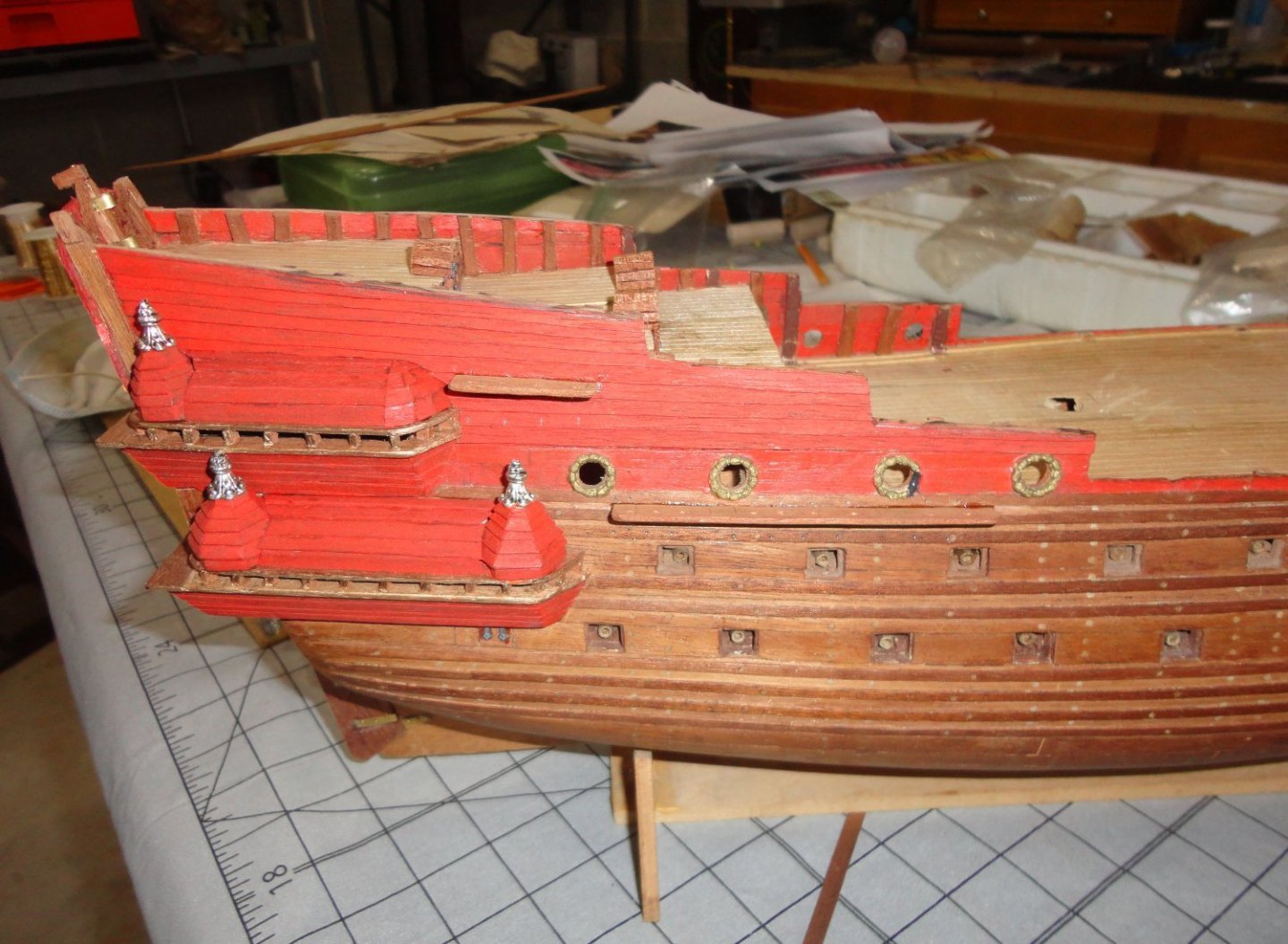
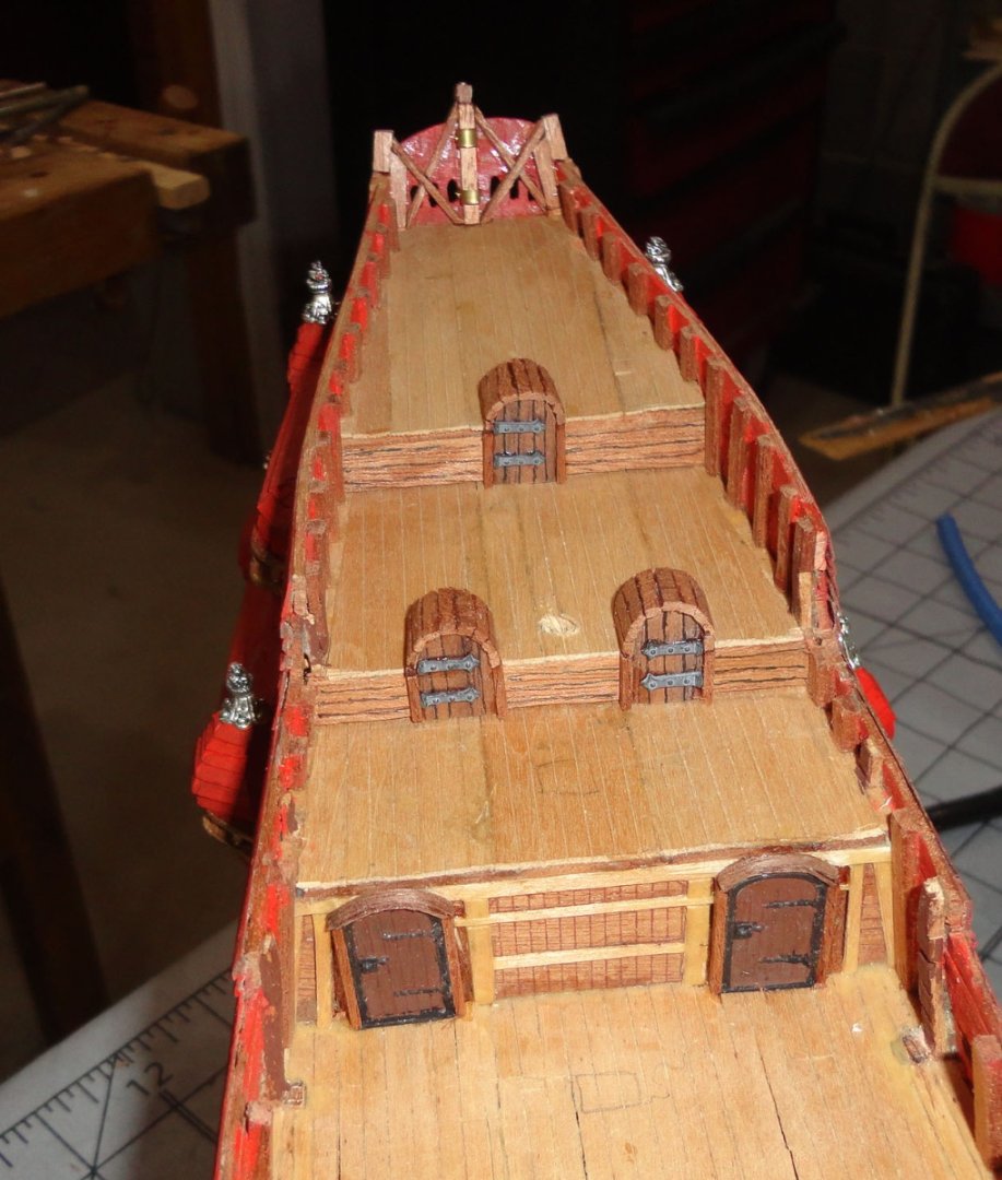
'Seems I decided to put the doorways on the stern decks while what 'next' to do was pondered. It's basically going ahead without instructions, but making them up as I go. The large doors on the weather deck are not where they should be, but previous work (out of the old box) forced them where they ended up. The voids behind them were filled with balsa chunks, covered with veneer, then two cast doors from a parts kit were epoxied in place (after painting). They looked 'stuck on' so I put frames around them. The 3 other doors higher up are about where they should be, and were made from shaped balsa for the headroom, backed with veneer (CA for speed) and front door panels were added. From thin stock the roofing was glued around the top plank by plank, and side frame pieces were added. A thin black lining pen marked planks on the doors, and scrounged port lid castings were glued on as hinges. Then a dab of Titebond glued the door assemblies into place. Ladders from level to level will be added. I'm fiddling now with the channels, which should go in with lower deadeyes before I start putting the 500 tiny brads into the hull, thus there may be a few days before there is something worth showing. I'm not 'on the clock' ... unless the Admiral starts giving orders.
-
I googled Dusek (new to me) and found they are a Czech supplier of a number of kits - including what I presume to be 'new old stock' of the GH they list as Mamoli (still listed as 1:53 when it is really 1:70) ... as well as they own version of the GH with guns below the weather deck. My next step is to try and 'inventory' kits and scratch builds of the GH for 'commonality' ... a sort of 'crowd wisdom'. I think that term arose from an experiment where over a hundred random passers by were asked to guess how many candies were in a big jar. The answers were all over the place, yet when the numbers were averaged once the data was collected the answer was very close to the actual number of candies in the jar! The experiment was repeated and found to have statistical significance. In my old profession of manufacturing/industrial engineer (sad to say I was made redundant after 30 years with the mass exodus of many types of manufacturing from the U.S. to other countries), I was tasked with creating the equivalent of an 'intelligent system' of setup and run times to streamline shop loading for a variety of complex CNC machined parts. The 'run times' were easy, but many had failed to 'crack the nut' of reliable rating setups that could take over 12 hours in some cases (most were in the 2 -6 hour range). The solution was to document the work content in common usable subunits, each previously built up of component units having many dozens of motion sequences typical for CNC operations. The times for small motions had roots with Gilbreth's (of Cheaper by the Dozen fame) work with 'therbligs' (micro motions), and became usable international values with H.B. Maynards MTM data (Methods Time Measurement). Many developed easier to use systems based on combinations of MTM data. Long story short, my own system combined hundreds to thousands of subunits. Although the accuracy of any individual group obviously varied, the combination of MANY produced what is know as the 'leveling factor'. That is, all the plusses an minuses effectively 'canceled each other out' to produce reliable information.
-
There was a 7-up Kung Fu parody commercial in the 70s - Cola nuts - Uncola nuts ... can you choose wisely? (Kid grabs 7-up) ... Well done Weed Hopper.
- 1,508 replies
-
- 1
-
-
- Le Soleil Royal
- Heller
- (and 1 more)
-
You are right, sir - and I stand corrected ... the name on the box is indeed Mamoli. Age will sometimes 'mix names up' in my head, but at least I got the 'M' right. I have edited the error out of my previous post. The Mamoli GH version is still a pretty nice kit (nominally 1:53 on the box, but it is very close to the Airfix 1:72 GH - I have both for close comparison of kit contents). Mamoli has the armament on the weather deck (representing about a 19' beam on deck) where there is not enough room to have the guns recoil back without rolling up on the grates (or be loaded for that matter). The lines are similar to the full-sized reproduction GH anchored on the Thames for tourists 'Before' the side nacelles were added at the waterline to make the ship stable. If the Mamoli bulkheads were modified by 3 scale feet per side at the waterline and the natural tumblehome continued up from there, there could be sufficient room for cannon use on the weather deck. Airfix has the broadside armament on the deck below (as most other versions have), and the sternmost gun port is lower, consistent with the change in deck level under the quarterdeck of a race-built galleon. They place two lighter guns per side on the weather deck. The first port on the gun deck is also a little lower and spaced further apart than the rest ... which got me thinking about DeSilva's sworn accounts of 14 guns for broadsides (7 per side) plus '4 at the bows' (ergo 2 astern and 2 forward) - but there were doubts as to whether 2 heavy guns would be of use on the forecastle deck with space restrictions and the sail on the bowsprit, which appear to have a typically high angle on the many period illustrations of contemporary vessels posted by Krill and others on MSW. If the first port on the gun deck (below the weather deck) was nudged a little forward where the bow curves, it could indeed be a forward firing gun (reference the drawings of the Vasa contemporary in another MSW thread) - one on either side. That would leave 5 heavy guns (port and starboard) for broadsides, plus the 4 lighter guns on the weather deck. With the 2 stern cannon, that would make 18 guns for the principal armament - in agreement with DeSilva. I rather like this idea ... of course speculation, as are all GH builds. Good pictures go the 'Drake cup' are hard to find, but a side view of the silver GH on top I recently viewed had a couple square openings below the weather deck (emulating gun ports there), and what was previously thought to be 'ports' on the weather deck is the jeweler's representation of a railing there and also on the quarter deck. All food for thought, I suppose.
-
Your galleon is a masterpiece in every respect ! It shows what can be achieved with patience, research and skill - regardless of the primary hull medium. I tip my hat to you, sir.
- 228 replies
-
- 1
-
-
- spanish galleon
- lee
- (and 1 more)
-
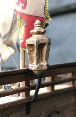
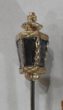
Wow, I just LOVE your build ! Model ships from the eras where most of the wood shows are quite attractive. So much to learn from well-done builds like yours! I scrounged the same AL lantern casting from a San Juan kit (bought for building materials) to use on my project, and perhaps it is the only thing that could (and still can) be 'pimped' a little on the Santa Maria. I tried to file off small parting lines on the casting (and I see now that there is one on an under surface that escaped me) with mini files, then the 'inside' surfaces of the lamp casting were painted flat black. I cut relative thin, clear plastic (you know, the kind that is vacu-formed to encapsulate a lot of things sold today ... and can make it hard to get the product free) into 'window glass' for the lantern. The edges of the panes were beveled slightly by holding with needle nosed pliers and rubbing the edge at an angle against sandpaper. Each pane (in turn) was test-fit to an opening, then cautiously fixed in place by a tiny amount of CA at the corners ... followed by tiny dabs of accelerator to lock in place. Then gold enamel was painted on with a micro-applicator between the panes, and a fine brush elsewhere. Two photos are below for comparison. Fair sailing, mate. Johnny
- 236 replies
-
- 1
-
-
- artesania latina
- kitbashing
- (and 2 more)
-
Good point. For those 'visually oriented' pictures can be worth many words ... and videos more so. E.g. the OcCre build video of their Endurance (out of the box, ergo no 'busting') I found very instructive, even though the repetitive portions had to be compressed/omitted so one can watch the entire build in a reasonable time. Only some kits have these videos, but there are videos of certain functions - like how to plank - that can be found on-line if searched out. And, as noted by a previous post, there are multiple MSW build logs of many ships available in kit form that can be perused as needed. Thus OcCre kits (my opinion) have good value for the money, opportunities to enhance according to builder inclination, and at least average to somewhat above average instructions and sometimes other resources to build. Woody Joe kits have many pictures for their well-engineered kits, which is fortunate since all the text is in Japanese characters (I found them tedious to translate even with a Google ap) - so that is a 'good news - bad news' situation. Artisania Latina kits are 'middle of the road' instruction/photo wise - perhaps because they are selling to many European countries and have to include a number of different languages. In their San Juan kit (which I bought from a local store for building materials - but would be fine as a 'first build'), there are some pretty good drawings and a number of photos. They do admit that what they show for rigging is 'simplified', so a builder wanting more complete (and more accurate) rigging must find instruction elsewhere. I have an old Mamoli kit (Golden Hind) that has many decent (and large) drawings to supplement their average, multilingual instructions. Too bad there was that fire at Mamoli, so my guess is that the 'old stock' (pre-fire production) that can sometimes be found (Ebay, yard sales/flea markets) are pretty good. ' By comparison, 'older' Billings kits (pre laser-cut vintage) can offer challenges in both building and instructions (per my own experience). Newer Billings kits are much improved, and I have two that I think are fine (Oseberg and Roar Ede).
-
3D printed homes.
Snug Harbor Johnny replied to allanyed's topic in CAD and 3D Modelling/Drafting Plans with Software
They've just tested a rocket engine that was 80% 3D printed ... not sure if I'd want a ride on that. -
Shipwreck of the schooner Ironton found in Lake Huron
Snug Harbor Johnny replied to DelF's topic in Nautical/Naval History
Well, 'treasure/artifact hunters' will have a GREAT deal of difficulty if they want to try and dive at the site of Shackleton's Endurance ... 😉 -
Back in the day when making paper covered rubber powered airplanes on a small bench next to my Dad's (as he made silk covered RC planes), the paper was glued to the fuselage and wing assemblies (pulling reasonable smooth). After the glue cured, all it took was a light spray of water, and the covering dries nice and taut with no wrinkles (if the edges had been pulled smooth when gluing). I flew my planes as-made, but Dad also treated his silk covered planes (once shrunk) with Aerogloss 'hot fuel proof' dope to get a smooth shiny finish that could be wiped clean of any oily exhaust from the single cylinder gas engine that powered the craft. Those were early days, and as time went by a product was developed called Monocote - a special film (a form of shrink wrap) that was glued, then shrunk tight with a hair dryer. No more silk (or stinky dope) after that.