


Snug Harbor Johnny
-
Posts
1,500 -
Joined
-
Last visited
Content Type
Profiles
Forums
Gallery
Events
Everything posted by Snug Harbor Johnny
-

USS Texas (BB-35) - in drydock
Snug Harbor Johnny replied to Kevin's topic in Nautical/Naval History
How about this 'build' (incomplete, as many of ours are ...)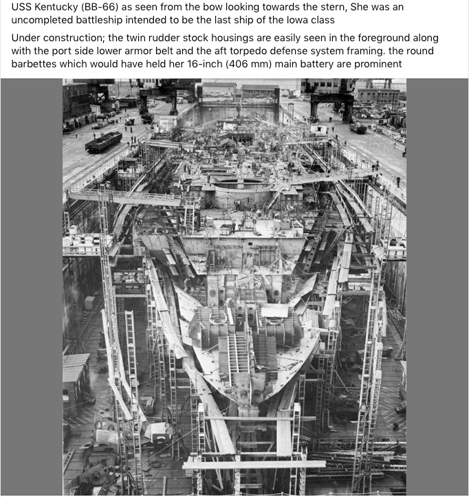
-
National Geographic's "History" magazine just came out, and includes an interesting article on Greek triremes.
-
USS Texas (BB-35) - in drydock
Snug Harbor Johnny replied to Kevin's topic in Nautical/Naval History
'Guess "links" sometimes go off into Neverland. A safe way to post an image is to take a 'screen shot' of it (a form of WISIWIG that merely duplicates pixels), then drag the image onto a post. -
A popular degreaser until about 20 years ago was 1,1,1 trichloroethylene (aka 'Tri-chlor'), and there were open bins of it all around one factory I used to work for. You could buy it in cans at the local hardware store as well. Due to various toxicities (as well as VOC concerns), it has been replaced with something else. (For how long?) Also, I remember lead (or tin-lead) tinsel for Christmas Trees. We'd all play with the stuff, but never ate any.
-
'Brings to mind an old yarn ... There once was a man from Nantucket, Who kept all of his cash in a bucket, But his daughter, named Nan, Ran away with a man, And as for the bucket, Nan tuck it. Then he followed the pair to Pawtucket, The guy and the girl with the bucket, And he said to the man, He was welcome to Nan, But as for the bucket, Paw tuck it. "Nantucket" - It rhymes in our head, With something that shouldn't be said, Around mothers and Vicars, And those with weak tickers, (Unless you've invaded their bed !) 😉 What arrrrrrr ya doing?
-
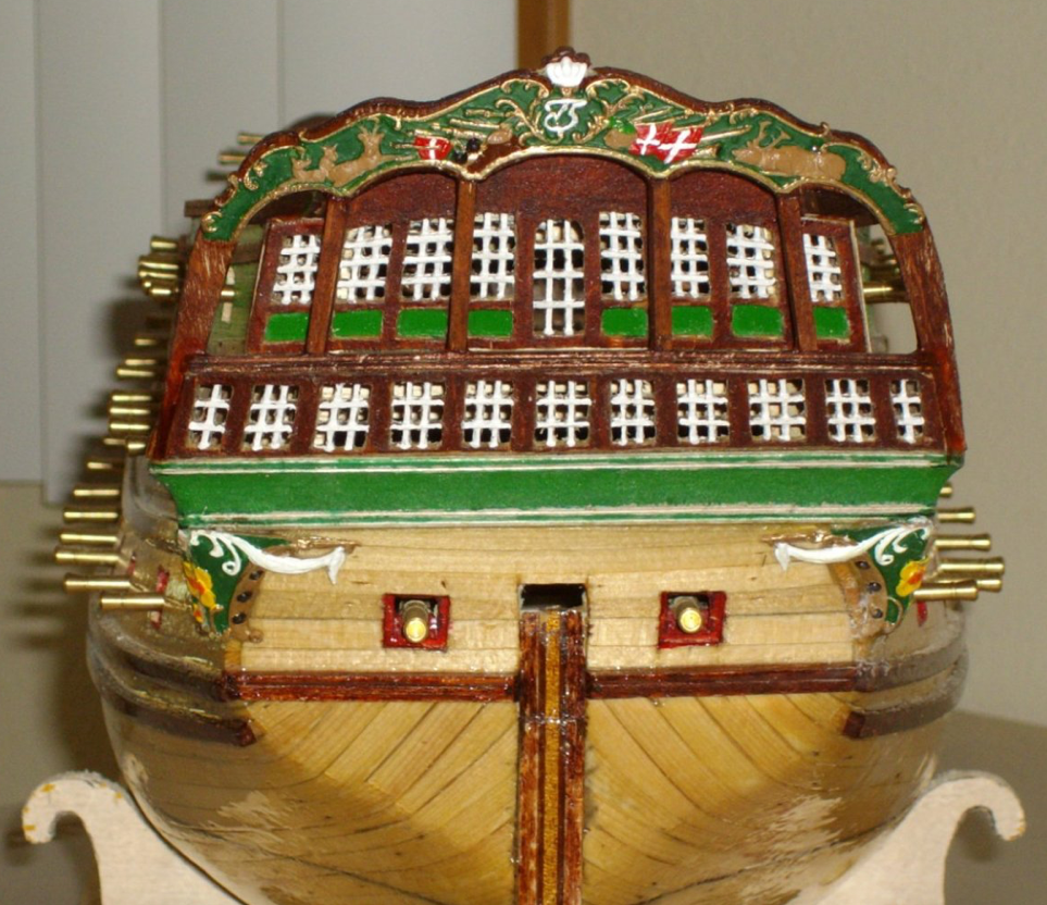
'Just saw a post of a Norske Love build that has the 'transitional' tuck we've been pondering. Picture below:
-
USS Texas (BB-35) - in drydock
Snug Harbor Johnny replied to Kevin's topic in Nautical/Naval History
The pictures in the previous posts seem to have 'vanished', but i just found something of interest to throw in ... By early 1942, it was determined that Oklahoma could be salvaged and that she was a navigational hazard, having rolled into the harbor's navigational channel. Preparations for righting the overturned hull took under eight months to complete. Air was pumped into interior chambers and improvised airlocks built into the ship, forcing 20,000 tonnes (19,684 long tons; 22,046 short tons) of water out of the ship through the torpedo holes. Twenty-one derricks were attached to the upturned hull; each carried high-tensile steel cables that were connected to hydraulic winching machines ashore. On 28 December, Oklahoma was towed into drydock No. 2, at the Pearl Harbor Naval Shipyard. Once in the dock, her main guns, machinery, remaining ammunition, and stores were removed. The severest structural damage on the hull was also repaired to make the ship watertight. US Navy deemed her too old and too heavily damaged to be returned to service. Disaster struck on 17 May, when the ships entered a storm more than 500 miles (800 km) from Hawaii. The tug Hercules put her searchlight on the former battleship, revealing that she had begun listing heavily. had begun to sink straight down, causing water to swamp the sterns of both tugs. As the battleship sank rapidly, the line from Monarch quickly played out, releasing the tug. However, Hercules' cables did not release until the last possible moment, leaving her tossing and pitching above the grave of the sunken Oklahoma. The battleship's exact location is unknown.
-
True enough, Steven ... I forgot how SHORT some of those doublets got ... plenty of ventilation for the (uh) 'bits', and the historic precedence for the micro-skirt. Now your model of Henry VIII's flagship fits right into the 'padded codpiece' era - and Henry liked to boast of his prowess.
-
Thats German for 'excellent' .
-
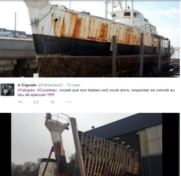
After poking around I found two images (one above the other) that appear to show that wooden framing was 'skinned' in steel (by the looks of the rusting patterns) ... perhaps this is why the Billings kit has a plastic hull - after all, the metal was painted and there would be no plank or grain marks. There seem to be slight bumps where fasteners of some type attach the metal skin to the internal ribs. Check out the available build on MSW, and builders seem to use the material provided (with all sorts of enhancements for equipment on deck, etc.).
-
Ausgescheishnett
-
Don't for get the codpiece ! 😉
-
There was a brand with red tinted glass called 'Red Head' extinguishers - and one old factory I worked for had a few upstairs.
-
Note how the tie is tucked between the second and third buttons to keep the lower part out of the way when working. Now when I started as an industrial/manufacturing engineer, the factory supervisor said that only 'clip on' ties were permitted on the shop floor ... due to the potential hazard that a loose end could get caught in a machine and cause a serious or fatal accident. A clip-on could get yanked away without taking the wearer's head with it. Still, even with a clip-on, the ends had to be tucked between the second and third button OR held close with a horizontal tie bar. However, removing the tie when going to the production floor was tolerated - if the tie was worn once coming back to the office. We also had to wear safety shoes (having steel inside the toe area), and our glasses had to be safety rated. Those not wearing glasses had to don nonprescription safety glasses provided by the office. Professional staff had to come in wearing a proper suit (where the trousers, and suit coat were of the same material - a dark color, perhaps with pin stripes - but NOTHING gaudy). Management had vests, whereas engineers, planners, etc. did NOT wear vests - as that would be presumptuous. Also managers did not take off their suit coats, whereas staffers DID remove the coat on arrival - and often rolled up long shirt sleeves if going to the floor in the machine shop to work on a process or problem. Oh yes, those were WHITE dress shirts. A few years later, a very light blue or yellow shirt became passable, but ties were still required. Many years later, the idea of "dress down" Fridays came into vogue - where non-suit slacks and other colors of shirt (including short sleeved) were OK. This evolved into jeans and totally casual clothes - and everything went 'down hill' from there.
-
Rigging - how to / tips
Snug Harbor Johnny replied to Mario Pires's topic in Masting, rigging and sails
The Admiral does beadwork, and has 'bead reamers' that are pretty narrow - they can be found in craft stores that sell beading supplies - or on line. -
Worth salivating over !
-
You're doing just fine, mate. I know the challenges of building a kit that has variations form 'reality' ... as the Vasa exists nearly fully restored in a Swockholm museum - so we KNOW what the original looked like ... and I'll have to 'bodge' through as best as I can, given the work already done in my youth. In the case of the Mayflower (also true of the Golden Hind and other ships of that era), we DON'T know what is 'right' or 'wrong' because we do not have the originals, there are no photographs (not invented yet) and the artwork is often conjectural. You are certainly free to exercise some leeway in artistic license.
-
Ahoy! The supplied planking does look a nit thick for the scale of the kit... but you can still 'plug away' to get used to working with wood. (The rigging will be a challenge unless your deadeyes and blocks are larger than for scale.) One thing that can help you 'fair' there hull is to glue balsa or basswood 'filler blocks' between the frames (bulkheads), and then plane/shave/sand down to the level of the frames so the hull curvature is smooth. If any frame is to low (as the smooth form develops ... note that you should bot be planking until the hull is faired), strips of wood can be glued to the edge off the frame to 'bring it up' to the needed level. When planking, get some wood strips around half the apparent thickness of what we see in the photos. You can soak a little (not too long), heat with an iron or blow drier, and rough bend the plank while still warm. There are several logs showing alternative planking techniques. Since you will be painting the hull, don't fret about 'perfect planking', but get your feet wet in the building process. You can likely have a nice 'standoff scale' model when done. I can recommend the Endurance by OcCre (Shackleton's ship), which could be a good 'next step' There is a review of the kit in the kit review section, and a complete build by HakeZou, plus a build in progress by Clearway. Don't worry about kit modifications, as you can build it 'out of the box' and get a very nice model - in approximately 1:72 scale. The building and rigging is much easier in this scale. The instructions are pretty good AND there is a video on line made by the kit manufacturer showing EVERY step of building it ... nearly in 'real time' (some breaks for repetitive actions). There are no guns (thus no gun ports and tackle) needed, no need to copper the hull - as the original was painted with newly popular anti-fouling paint (rust red). There are many pictures of the original on line if you want to look. Only the fore mast has square sails, as the other two are fore-and-aft rigged - a real time saver. And there are now a few picture available on line of the actual ship as she lays on the bottom in Antarctic water. Best of luck ! Johnny
-
Ahoy Dave ! I just received the Underhill Clipper book (great condition other than some clear tape to reinforce the paper jacket) priced at $27 and change (plus $5 shipping) - and it is an excellent investment, possibly tied for the best rigging book I've found to date. It was certainly great advice from Rob Reiderrich, who is justifiably a clipper 'guru'. When one takes ALL the detail into account, I can see why undertaking a clipper project smaller in scale than 1:96 is not practical unless one omits or simplifies a few things. But there are well rendered builds at 1:96 and larger with virtually all the 'bells and whistles'. There are an arguments in favor of building an 'early' clipper (e.g. the Sea Witch of 1846 - prior to significant changes in her rig post 1850) ... 1.) The hull length is 40+ feet shorter than the Cutty Sark or Thermopylae, so a 1:72 scale will about about the same size as a 1:96 version of the other ships named. 2.) This was prior to Howe's split top sails (or split top gallant that is seen on later clippers), so the early ships sported four sails per mast (as seen on contemporary artwork) instead of the 6 sails often seen on later ships. 3.) The masting and sparring was all wood on the early ships, and there were fewer complex metal fittings that would arise as the art of the clipper developed. An interesting note is made in Underhill's book (which he admits focuses on the later clippers - often having steel hulls), on page 163 which talks about bunt lines ... There is a variation clearly shown (fig.150 on the same page) where two bunt lines can be worked with a single running line (via two 'helper' single blocks rigged to the shroud above the yard). That way, the number of lines having to go through fairleads and down to belaying pins on bulwark pin rails can be significantly reduced. The 'more common' way is to have every bunt line find its way down as shown in plate 34 (page 188) ... a veritable 'jungle' of lines below the the course (main sail). For a modeler's sanity, the leech lines (one on either side of each sail) might be omitted, but the reef tackle should remain. One can also consider (in lieu of individual leech lines) variant A. or B of figure 151 (page 169), where the outer bunt line is either bent to the leech of the sail (after passing through a 'bulls eye' at the base of the sail where a 'typical' buntline would fasten) - or the bunt line can pass through a bulls eye at the leech point (after routing through a thimble on the sail face) and then down to the normal bending place at the foot of the sail. Either way, this could satisfy a builder who does not want to entirely omit leech lines - but would appreciate not having to rout individual leech lines to the deck. It is a relief indeed, to realize that 'slab lines' (that duplicate bunt lines on the back side of the sail, shown in figure 16 on page 17) are optional - as the text in the paragraph below the figure notes ... "the rest of the sail (is) gathered up by the bunt-lines and slab-lines (when rigged)." WHEW, so one by no means need incorporate slab lines, as that would add to the jungle of rope to be routed down and dealt with below. Rigging for 'early' clippers can be assisted by Peterson's book 'Rigging Period Ship Models' - that deals with a man-of-war in there late 1700s and early 1800s. Need to build a much earlier vessel? Try Anderson's 'The Rigging of Ships in the Days of the Spritsail Topmast'.
-
Thanks for these helpful tips. Your work is excellent, and I may only imitate. Learning first and planning is good advice.
-
So if all one has are 'gloss' paints, adding a little talcum powder will 'matte down' the finish. Now 'boiled' linseed oil was the principal medium (carrier) for colorants (pigments) in the 19th century - as well as artists oil paints, that were just a lot thicker to put in lead tubes. These paints can still have a 'sheen' of sorts when painted on a flat surface, due to the polymerization of the linseed oil. Note that RAW linseed oil takes forever to dry ... and never really dries 'completely'. So 'boiled' linseed oil refers to the addition (cooked in) of a metal salt that acts as a 'dryer'. That is, the added compound acts as a catalyst to hasten the oil into forming polymer chains with 'cross linking'. The most common additive was lead acetate - so called 'sugars of lead', due to the sweetness registered if tasted. Lead acetate was the first 'artificial sweetener' used in ancient Rome - a byproduct from boiling vinegar in lead pots (another story). Lead pipe plumbing quickly develops a lead oxide inner layer that gets mineralized in place - which prevents lead leaching. So old lead supply pipes in the U.S. don't present much danger if left undisturbed - yet complete replacement has been the safest policy. Thus the their of lead poisoning in ancient Rome was not likely to have been from the pipes, but rather from the artificial a=sweetener that only the well-to-do could afford. Anyway, lead acetate has a reddish orange color, which makes linseed oil so treated have an 'amber; color that you can find in very old paint sets now and then at a yard sale, etc. Modern boiled linseed oil has a manganese-based dryer. There was also a dryer developed in the 1800s called 'Japan Dryer' - one small tin will last a lifetime since only a few drops added to any old oil-based paint or varnish will 'restore' the ability to dry. I've digressed (as usual), but one can have a semi-gloss finish (with wood grain still showing) and still be 'in period',
-
Reading about the ship Donald McKay (1855) in Richard McKay's book, (pp 284 & 285) I found (parenthesized notes are mine): "The Donald McKay was fitted out with Howes double topsails, A decided improvement over the common rig then in use, and so we describe it below: "The lower topsail yard was trussed to the topmast cap, and instead of slings, was supported by a crane upon the heel of the topmast ... The upper topsail set upon the mast above the cap," (obviously bent to the jackstay of the upper topsail yard) "and had its foot laced" (ergo bent) "to a jackstay upon the top of the yard below, so that no wind could escape between the two topsails." ... "The ship could be reduced to close-reefed topsails at any time, by lowering the (upper) topsails, which would then lay becalmed before the lower topsails, and the latter, if required to be reefed, could be held without the use of reef tackles." "In squally weather this rig proved invaluable, for sail could be carried to the last minute, as it could be reduced and reset without a man leaving the deck. Its economy in wear of canvas must also have been very great, for the sails were of manageable size, and had neither buntlines, reef tackles, nor clew lines to chafe them." ... "and could be worked with fewer men than a vessel of the same size, having the old rig." I have 2 questions: 1.) To be able to rotate (pivot) with the upper topsail yard, was the bottom of the crane attached to a metal ring and bearing plate at the heel of the topmast ? 2.) Does the text mean that ONLY the upper topsails had no buntlines, reef tackles or clew lines? They would need sheets (obviously), but the lower topsails would not require reef tackle. To furl the upper topsail in the lowered position, men standing on the foot ropes of the upper topsail yard could simply pull sections of the upper topsail over the top of its yard before lacing with grommet line - but would have to un-bend the bottom of the upper topsail from the jackstay on the yard below to wrap line around the furled sail above. Otherwise the foot (bottom) of the upper topsail would still be bent to the lower topsail yard - and would preclude the lower topsail from being pulled over its yard for furling. It would seem that the lower topsail would still need clew and bunt lines to work that sail as before (and described in the quoted text above "if required to be reefed"). If this pair of sails were not in use for a short period - whether docked short-term or at sea in a squall - the upper topsail yard could be lowered (and not furled), while clew and buntlines would merely pull the lower topsail up to the yard (sheets obviously slacked) - effectively taking in the lower topsail because it would no longer offer resistance to any wind. It might then (if docked) have the appearance cited in the book: "It looked rather clumsy in port, and this, we believe, was the principal objection urged against it by those who did not comprehend its advantages at sea. Ships, however, are rigged not for show in port, the, therefore, which is the most serviceable, is certainly the best."
-
Talk about a big screw ...

-
Is the bottom of the 'crane' mounted on a metal ring going around the base of the topmast? ... so it can pivot when the yard swings to either side? Rob will know the answer.


