DONATION DRIVE - SUPPORT MSW - DO YOUR PART TO KEEP THIS GREAT FORUM GOING!
×


allanyed
-
Posts
8,149 -
Joined
-
Last visited
Content Type
Profiles
Forums
Gallery
Events
Everything posted by allanyed
-
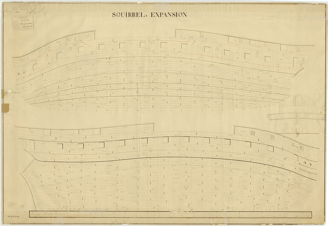
 Charlie, I know this subject comes up continually here, but if you study David Antscherls tutorial here at MSW on planking, and look at the fine finish on the planking that is achieved, you may wind up buying sheets and cutting the planks from the sheet stock. It is sure a lot easier than forcing straight planks of a single size into position by edge setting, (based on my own experience.) You can see from a planking expansion drawing that straight strips are not really used. A picture of the planking expansion for the HMS Squirrel follows and the schooner Ernestina planking expansion is attached as a TIFF file. The Ernestina drawing can be downloaded from the Library of Congress for free in several different formats and are extremely clear to show the plank shapes for that particular hull. I realize some planks can be tapered and then easily forced into position without too much trouble with edge setting, but depending on the hull shape and the hardness of the wood you are using, a lot of them want to buckle. Allan Planking expansion port side.tiff
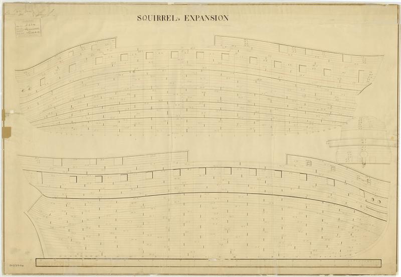
- 362 replies
-
- 4
-

-
- active
- revenue cutter
- (and 1 more)
-
Gas man What scale is the model? If 1/8" to the foot, 3mm false keel would be about 11" thick which is probably reasonably accurate. (3.175mm=1foot) , 2mm thick planking is the equivalent of 7.5 inches which is way too thick. It should be about half that if single planked. If it is 1/4" scale, the keel seems too narrow but the 2mm planking is probably pretty accurate. This of course would be for a single layer of planking. Double planking means the layers should each be half that thickness. Allan
- 5 replies
-
- 3
-
-
- Planking
- Lady Nelson
- (and 1 more)
-
Les, Lavery gives a detailed description on page 233 in his book The Arming and Fitting of English Ships of War. From about 1625 onwards there was an increasing tendency to hoist all boats aboard and had probably become standard by the second haf of the seventeenth Century................... ....Because the largest boat were stowed between the mainmast and the foremast.............a complicated tackle was needed for hoisting them in and out................the first stage was to raise the boat from its position amidships. Two pendants hung from the masts, one from under the top of the mainmast, the other from under the top of the foremast. When in use these were joined together by another rope known as the triatic stay, which was the same length as the boat. A tackle was hung from the lower end of each of the pendants, one to lift each end of the boat. Once the boat had been lifter, it had to be swung outboard. the main and fore yards were angled inwards towards one another, and a tackle was extended from each yardarm to one end of the boat. If the boat was heavy, the yards had to be supported with extra ropes in addition to their normal lifts. Other ropes led from the bows and stern of the boat to the deck and were used to control its motion. The boat was swung outwards until the tackle from the yardarms took the weight,, and the it was lowered into the water. The procedure was reversed for hoisting the boat in. Hope this is of some help. Allan
-
Nigel, Yes, Titebond is one of my top two choices, the other being Elmer's Carpenter glue. Allan
-
Nigel I have no personal experience with kits but regarding the glue, aliphatic glue is PVA that has been modified to be stronger and is commonly called yellow glue or carpenter's glue. If there was a poll here, I am pretty sure it would be the most commonly used glue for binding wood to wood. Epoxy is excellent for times when you have a tiny surface area for the glue. Cyanoacrylate might work for some things, but I have never found where carpenters, PVA or epoxy are not better choices, are less dangerous and have no sheer problems like CA. Allan
-
Microwaving the wood?
allanyed replied to a topic in Building, Framing, Planking and plating a ships hull and deck
Susan There is a thread on dry bending that is currently active in this particular forum that you may find interesting. Allan -
MS Fair American rigging plan leaves alot to be desired.
allanyed replied to JPAM's topic in Masting, rigging and sails
JP Based on a quick Google search I believe there is a contemporary model of Fair American at Preble Hall on which modern kit plans are supposedly based. I do not recall seeing it myself on my few visits, but I am sure they can let you know. There is said to be no contemporary set of plans in existence. You might want to try to contact Preble Hall for some help. I think there is still a model club known as the volunteer model shipwrights that meets there in the museum shop (oh my, what a nice shop they have to use) and possibly they can help you. Go to the Preble Hall website and it will get you started. museummodels@usna.edu Allan -
Michael, Maybe I missed it elsewhere, but what temperature are you setting it for when bending the planking. I know auto-ignition of wood varies with species, but was curious as to what temperature settings you have tried for the Castello. $99 does not seem terribly expensive and is worth the tranquility derived from not using her hair dryer! Allan
-
I agree with Mark about Chuck Passaro's kit designs. The big difference that I have seen from the posts here at MSW, is that Chuck builds these models and can help along the way. He understands the "how to" and knows materials that work and don't work. Also, his designs yield very nicely detailed and accurate finished models. Allan
-
Chuck, I may have missed it in an earlier post, but is the red paint also a Grumbacher acrylic? If so, which red, or is it a custom made shade? Are they straight out of the tube or thinned at all? I do like Grumbacher acrylics having used them for years back in the day when I tried my hand at painting on canvas and they are certainly easy to find. I don't have any desire to move back to NJ :>) , but I would have liked to be there to see the model up close and personal at a NJ club meeting. Allan
- 1,051 replies
-
- 7
-
-
- cheerful
- Syren Ship Model Company
- (and 1 more)
-
Pandora by marsalv - FINISHED - 1:52
allanyed replied to marsalv's topic in - Build logs for subjects built 1751 - 1800
Mars, I like your use of jigs, it assures consistency in sizing on the rings. And the adjustable jig for the chains allows one to make the various lengths that are needed as they do need to be longer as they go forward to aft with the angle change. What I cannot figure out is when you install the chains, they are not silver soldered. Do you install, fit them to length and then take them off, silver solder and reinstall? Thanks Allan -
Totally understood Ron Allan
-
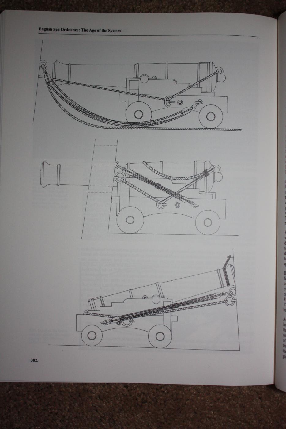
Sweet job on your project Ron! One note, and I hope you don't mind, next time the breeching rope needs to be long enough for the gun to be able to be brought completely inboard of the bulkhead and the train tackle ring far enough inboard to accommodate this. Allan

-
Mike, The Euryalus master's log is considered the most comprehensive on site log of the battle. The original is at Lloyd's of London but no longer available to be seen by the public due to its poor condition. It was transcribed by Admiral T. Sturges Jackson in his chronicles and I transcribed it in the Euryalus book, Volume I. There is also a transcription in the Euryalus book of the Adm. Collinwood letter to the Admiralty that was published November 6, 1805 in the London Gazette that you may find useful. You can find these on line but please feel free to email me if you would like me send them over to you. I would copy them here, but I use IE and I understand MSW does not allow cut and paste if you use IE. Allan
-
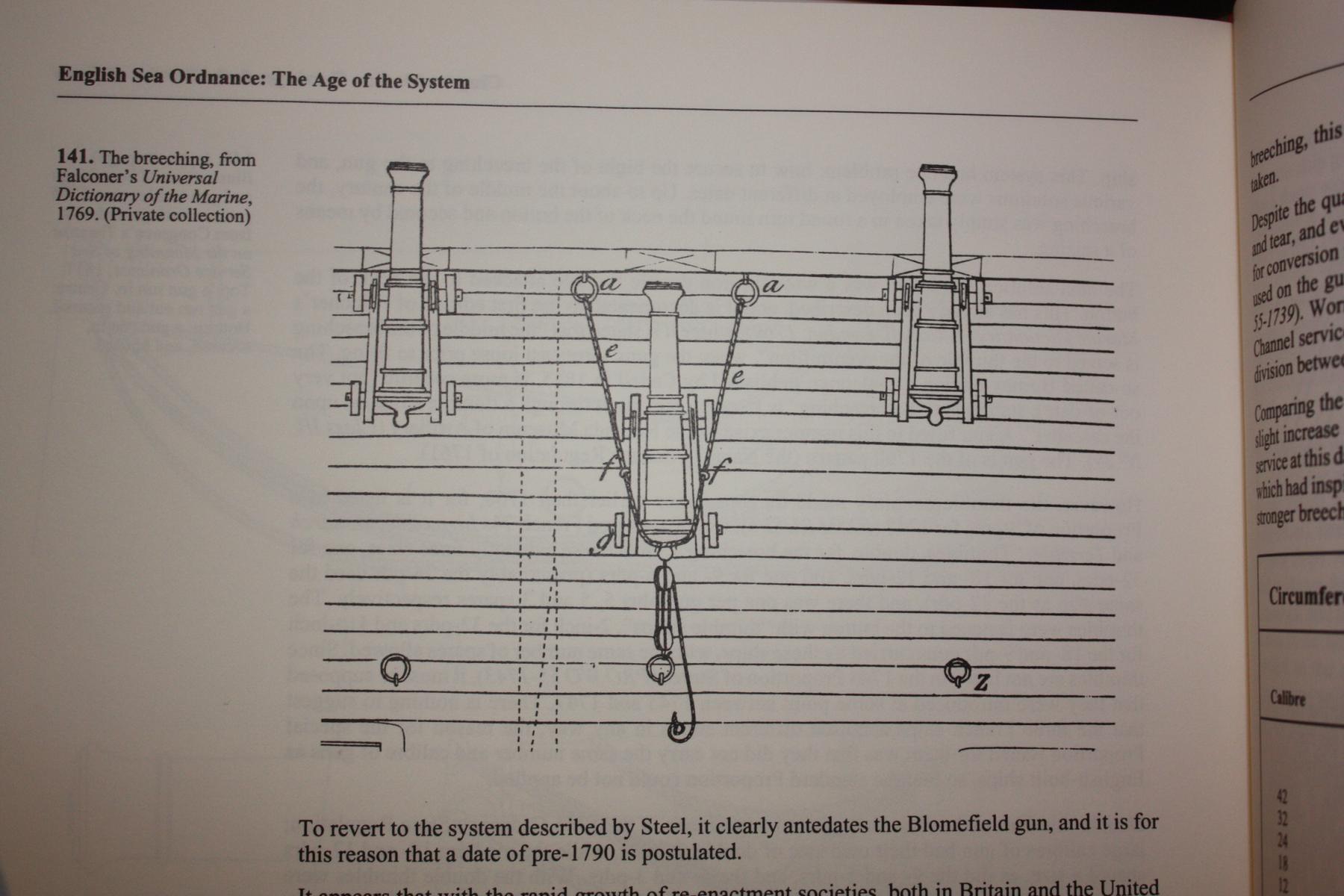
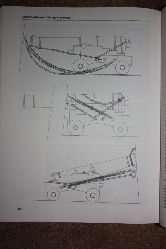
Ron The following may help. It is in Caruana's History of English Sea Ordinance volume 2, and is redrawn from Congreve's 1811 treatise. Top is gun run in. Middle is gun run out and secured. Bottom is gun run in , secured, and housed. Allan
-
Chuck It is the little things that I keep noticing and going back to on your model. The hatch coamings and head ledges' joints are really well done, the belaying pins look to be at scale, not the bulbous pins seen on so many models, rings and bolts look to be at scale. She is a beauty! Allan
- 1,051 replies
-
- 4
-
-
- cheerful
- Syren Ship Model Company
- (and 1 more)
-
Timothy I really admire your drawings. You CAD wizards really amaze me. Attached are two photos of six rates, 1730, and 1745 that may help you. There are more of them on the NMM collections site. Allan
-
Les, I also like W.E. May's book which includes the same scantlings found in Elements of Naval Architecture and are also given in Scantlings of the Royal Navy. Another great reference is Lavery's The Arming and Fitting British Ships of War 1650 to 1815. There are a number of drawings that can be found at the NMM Collections. Just write in long boat, pinnace, cutter, whatever is appropriate in the search box in the Collections section and they will come up. Some are clear enough to use from the site, and all can be purchased digitally and are extremely clear. Allan
-
Gaetan, You have far more invested in photographic equipment than most members have model building equipment. Very impressive to most of us point and shoot folks. Allan
- 728 replies
-
- 4
-
-
- le fleuron
- 64 gun
- (and 1 more)
-
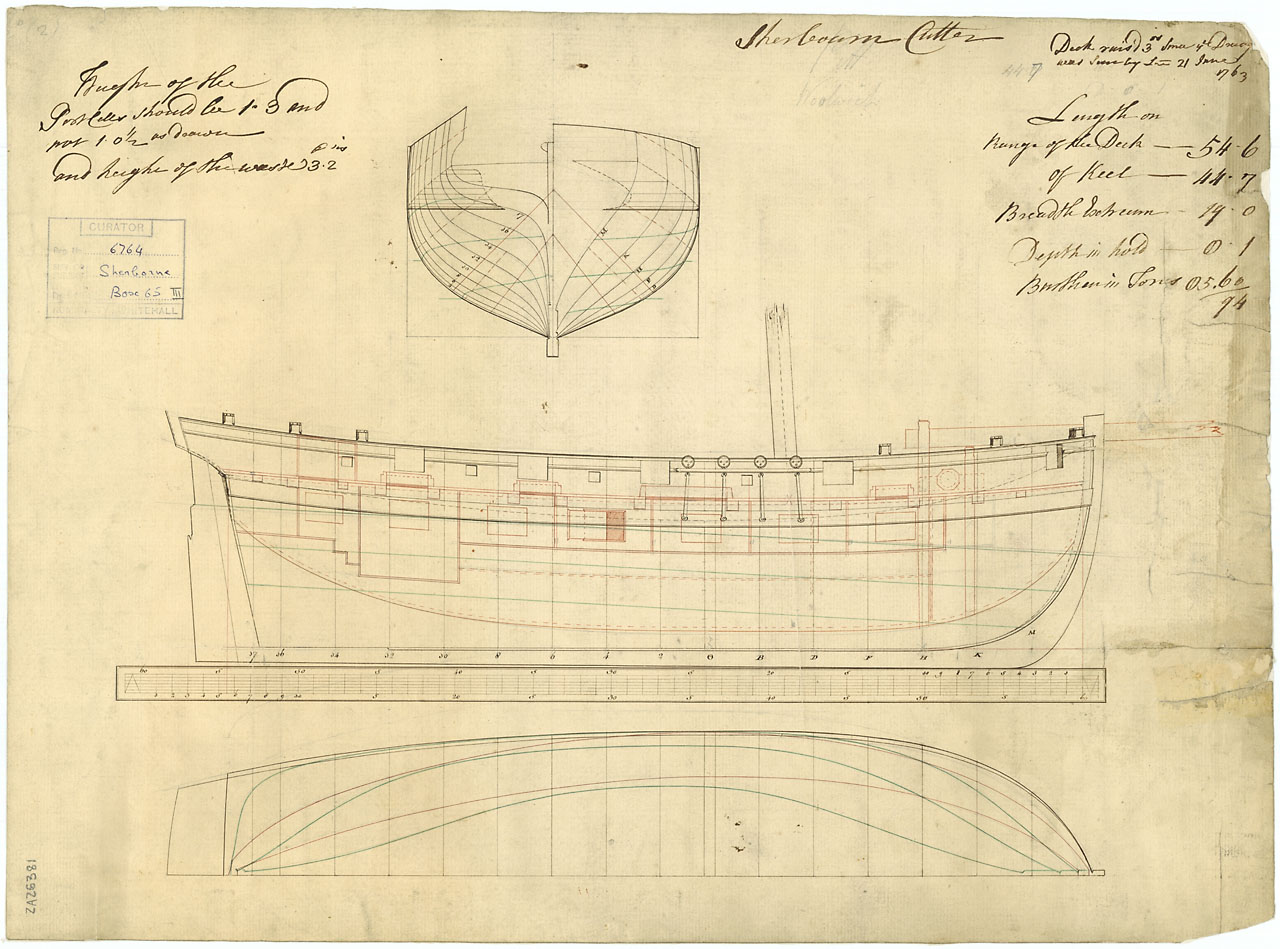
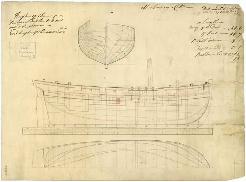
Gordon, I found your post interesting so did a little searching. There were 15 ships named Greyhound in the British Navy, including a 15 gun cutter 1763, and a 14 gun cutter 1780. But, I believe these are a bit large compared to the Sherbourne of 1763. The kit gives it as an 8 gun, but the National Maritime Museum written description for the Sherbourne of 1763, (and cited in Winfield's British Warships in the Age of Sail) say she carried six 3 pounders and 8 swivels. However, the original drawings show 4 gun ports on each side which would seem to indicate an 8 gun vessel. Wonder if it is a mistake in the description or there is a reason for the discrepancy. The drawings actually show another port at the bow, but not likely a gun port. These two forward most ports are not shown on the deck plan. Allan
-
Gaetan, I am no expert on the field of photography, but the best results I have been able to achieve are shooting outdoors on the north side of my house so the sun is completely blocked and the model is in the shadow of the house. I lay a sheet of photo backdrop paper, usually light grey, on the ground and run it up a wall so there is no seam. A little tape is used at the top. It is all then indirect lighting so very little or no shadow. Overcast day is best IMHO, still light enough, but virtually no shadows, glare, reflection etc. It only takes 5 minutes or so to set up. I wind up laying on the ground to take the shots, but not a hardship to do so. Allan
- 728 replies
-
- 3
-
-
- le fleuron
- 64 gun
- (and 1 more)
-
Your entire build log is beyond words. It is a joy to go back to earlier pages as well as current pages. Allan
- 728 replies
-
- 3
-
-
- le fleuron
- 64 gun
- (and 1 more)
-
I agree with Dirk, Bill Shorts book is a great resource if one is going to be using various burrs as part of the sculpting process. Allan
-
Chuck It sounds like you have already seen this book. If so, please share more information if you can, or is it as you said, just another book with photos of ship models that looks better on a coffee table than being useful in the shop? Allan
-
Inserting scanned object
allanyed replied to Mark P's topic in CAD and 3D Modelling/Drafting Plans with Software
Mark, I don't understand. If you are redrawing everything in pen and ink and pencil, I assume you will not draw the background rectangle so it will not be there when it is scanned in. I am definitely missing something here. Is your attached one of the carvings from the vessel? If it is, can you show this carving example in situ on the Caroline? That may help understand what you are going for. Allan