allanyed
-
Posts
8,149 -
Joined
-
Last visited
Content Type
Profiles
Forums
Gallery
Events
Everything posted by allanyed
-
 I totally agree with you Keith. Consider the hundreds, if not thousands of models at Preble Hall and RMG for starters. VERY few fully rigged models have sails. Not a big deal for schooners and similar vessels, but I think sails take away/block all the intricacies in the rigging and hard work that went into it for square riggers. Mine is obviously just one more opinion for our models of today, but the old masters seemed to have agreed. Allan
 -
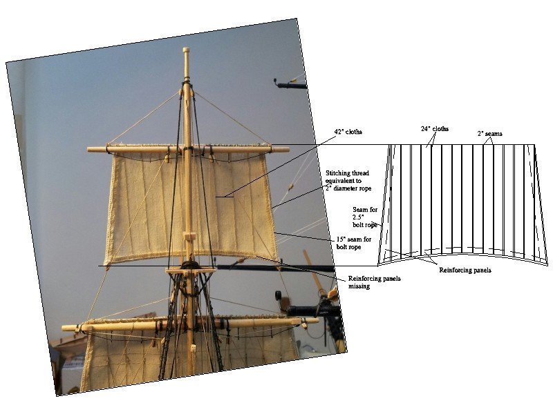
Daniel The sails in the OcCre kits and a number of other kits are cloth and there is no cloth that is to scale at 1:48 or smaller. You would need a thread count of about 2000 to match canvas. 1200 count exists for fine linens and does not look that bad, but you cannot sew seams to scale with a machine and it would be very difficult to do by hand. Consider that the cloths (panels) on most sails for the 17th -19th centuries were 24 inches wide and the seams had a 2 in overlap. The outer edge seams were a little bit wider plus there was the bolt rope and reinforcing panels at the corners and other places. Lees shows typical sails that will help you a lot. For making sails there is a great YouTube video on making sails from silk span by Tom Lauria as well as the great booklet by David Antscherl available for $7 or $8 from SeaWatch books. I found that a combination of the video and booklet work best for me, but both have great how-to information that you can try to see which works best for you. There have been a lot of posts here at MSW on making sails from non-woven materials like silk span that will help you as well. To be sure, there are good looking cloth sails on models, but they are far from being to scale if that is a consideration for you. If being to scale is not a concern, by all means use the kit materials. For a comparison the below may help see the difference between what another member here called the OcCre door mats and a sail . The sketch does not show all the reinforcing patches, but these can be found in a number of sources. Allan
-
Your build continues to be an inspiration. You commented a while back Did Keith ever finish? Clearway's model really is very nice but I hope you are going to make your own sails instead of using those out-of-scale things from the kit. Allan
-
Spritsail yards on Niagara and Constitution
allanyed replied to gak1965's topic in Masting, rigging and sails
Makes sense Phil, just as the cross jack carried no sail but was needed for the spread of mizzen top sail. Allan -
Good to have another Allen on the membership roll. We have a bunch with a variety of spellings, just need one from France (Alain) to round things out. Allan
-
Finding miniature bolts
allanyed replied to Mark m's topic in Metal Work, Soldering and Metal Fittings
Thanks Mike, much appreciated. For 1:12 scale they seem pretty reasonable. But at 1:48 they are gigantic with the head is 3.3" and the flat to flat on the nut is 4.5". Allan -
I do not blame you at all. Chuck Passaro has had incredible success with Alaskan cedar. Hopefully there are suppliers for this species in strip and sheet. Allan
-
Hamilton, GOOD FOR YOU. If you do replace the wood provided by the kit, which is a GREAT idea, you have the luxury to choose from a number more appropriate species that will lend themselves well to spiling or edge bending ala Passaro and replace all the walnut which is usually brittle and almost always porous rather than tight grained. Allan
-
Finding miniature bolts
allanyed replied to Mark m's topic in Metal Work, Soldering and Metal Fittings
Hi Mike Are the nuts 1mm outside dimension or are the screws 1mm diameter? 1mm is nearly 2" at 1:48 scale so larger than probably would be appropriate if being to scale is a consideration. Allan -
Greg and Druxey Pins in two sections? I looked through TFFM with no luck, then voila, there it was described in book The Fireship Comet. Will be giving it a try next time I need belaying pins. Thanks again!
-
Would the high quality tubed acrylic artist colors work well in this device if they were thinned? No more worries about brush strokes if it does!!! Thanks for posting the info on this unit EG.
-
Makes sense to me.😀 Thanks USS Frolick
-
Finding miniature bolts
allanyed replied to Mark m's topic in Metal Work, Soldering and Metal Fittings
I just did a quick search and found a source in the United States and another in Canada for taps and dies down to 0.0118" diameter which is UNM 0.3 thread. This would be the equivalent of about a 1/2" bolt at 1:48. Would this be small enough for your project? There are probably comparable sources where you live if you are not a resident of Canada or the United States. Allan -
I am with you Greg. Some of the best entertainment I remember was after fishing and docking our boat we would stroll to the public launch ramp and would just sit with a beer a watching folks back their boat trailers to the ramp. One guy had cards marked 1 to 10 and rated each attempt and held them up so we would then cheer or jeer as appropriate.
-
Are you running the Dragon's Back in Wales next month? Our youngest son and our daughter in law (both 47 years old) are running it this year. 200 miles of agony in my opinion. I like your idea of a cigar and pints much better. Give me any good pint and an H. Upmann and the heck with running. Cars (or even horses and mules) were invented for a reason you know.😀 Allan
-
I believe he was referring to the galleries as there was no round house on the Surprise being only a 6th rate.
-
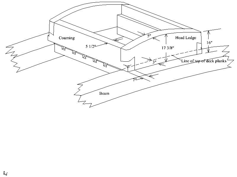
Doug, Take a look at a few photos of contemporary models when you have a chance. The gratings invariably are set up as in the sketch above. Also, keep in mind that the head ledges usually have some rounding, often steeper than the deck beams. Not so much on the lower decks, but more so on the upper decks. One pic is below from a contemporary model at Preble Hall as an example, as well as a sketch we did for volume II of Euryalus showing the rounding of the head ledges.
-
Hi Dziadeczek I was not referring to the capstan which obviously has nothing to do with a round house. A round house, or poop (from the French for stern, La Poupe) is a totally different thing. The poop sat atop the quarter deck. Examples of 50, 64 and 74 gun ships follow. I may be wrong on this, but I believe the term came from the fact that the deck beams of the round house had a round up from 8" to 12" depending on the era and size of the ship. Compare this to a range of 6" to 8.5" on the upper decks, and 3" to 6" on the gun deck, again depending on the era and vessel size. Allan

-
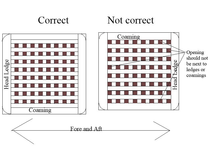
Hi Doug, One point to keep in mind going forward, the grating, the opening of which are about 2.5" to 3", should be closed on all four sides rather than open. I find it easier to make the gratings then fit the head ledges and coaming pieces around it. Overall the size may be slightly different than on the plans, but very close if not right on the mark. Allan
-
As stated above it takes a library, albeit a small one to get started. Great advice has been given above. I highly recommend Goodwin's The Construction and Fitting of the English Man of War and Brian Lavery's The Arming and Fitting of English Ships of War 1600-1815. For rigging, there are several, but the best by far, and I think many would agree, when it comes to explanations and accuracy, is David Lees' The Masting and Rigging of English Ships of War 1625-1860. There are also free sources that are useful. The formulas in Lees' book for sizing masts, spars and lines have been put into a spread sheet by the late Danny Vadas and available here at MSW in the Articles data base. It is spot on except for the period from 1670 to 1711 where he did not use the right initial formula so everything is completely wrong for that time span and should not be used. To learn how to properly plank ships of that era the 4 part You Tube Video by Chuck Passaro and the article Primer on Planking by professional ship modeler and author David Antscherl, both of who are members here, which can be found here at MSW in the Articles data base are hard to beat. Even if you are kit building, these articles and books will help you immensely. And there are thousands of free low resolution contemporary plans and photos of models on the RMG Collections site as well as free high resolution versions of nearly 1000 of these (along with about 2000 low res) on the Wiki Commons site. https://commons.wikimedia.org/wiki/Category:Ship_plans_of_the_Royal_Museums_Greenwich It is all part of the journey and should be a most pleasurable one. Allan
-
PIllars
allanyed replied to allanyed's topic in Building, Framing, Planking and plating a ships hull and deck
Hi Mark, Thanks for the additional photos, they are great to see. MANY thanks for the compliment on my scantlings book, I really appreciate your thoughtfulness in mentioning it. Allan -
Either this or the Primer on Planking by David Antscherl in the Articles section here at MSW will serve you well. I have used both methods and find them to be equally effective in yielding tight fits and proper tapering, especially at the bow to avoid, or at least minimize, the use of drop strakes. Allan
-
Hi Gregory, This is probably just a matter of terminology, and your reasoning about the glass panes makes a lot of sense, but when I looked at the plans you posted on your build log there is no round house (poop) so this is a little confusing. I did find a contemporary model of a similar size ship on the RMG Collections site that does have glass panes on the doors of the bulkhead under the QD, but it looks like there may be panes on the center part of the bulkhead as well. Just as a side note, researching the scantlings in the various Establishments starting in 1719 , The Shipbuilder's Repository (1788) and Steel's Elements & Practice of Naval Architecture there is no poop (round house) on ships smaller than 50 guns. There are a lot of photos of 50 gun and larger ships at RMG that show the round house and the panes are on the doors as you suggest. Some of these models also show panes on both the poop and the QD bulkheads between the doors as well as on the doors. Lots of choices from which to pick😀 Allan
-
Hi Jon Wayne Kempson's paper in the Articles database here at MSW addresses the lofting of square and cant frames that may be of some help. DraftingShipPlansInCAD.pdf Allan
-
Keep up the good work!! I realize this is the first layer of planking so far. On your second layer of planking, will you be following the same sweep of the strakes where they follow the line of the gunports or more like how the planking actually laid as in the contemporary model of the Bellona below? I marked the run of the planking with a black lines so it is easier to see. For those that have not seen them, there are 8 great photos of the contemporary model of Bellona at RMG which are pretty clear even at the lower resolution and show the planking very clearly as well as the photos in Yve's Bellona build log here at MSW. Thanks for sharing your build! Allan