DONATION DRIVE - SUPPORT MSW - DO YOUR PART TO KEEP THIS GREAT FORUM GOING!
×


allanyed
-
Posts
8,149 -
Joined
-
Last visited
Content Type
Profiles
Forums
Gallery
Events
Everything posted by allanyed
-
 Your P-51 is fantastic and it brought back memories of the Red Baron P-51 that the late and great Daryl Greenamyer flew at the Reno air races and his quest for the altitude record in the F-104. I worked for PPG Coatings and Resins division back in those days which provided the technology and paint itself for the 104 and had the privilege of meeting him several times. Four of us flew up to Tonapah, Nevada from SNA in Orange County and was up close and personal at Mud Lake in 1976 when he was going for the low altitude speed record. He broke it unofficially that year, but made it official the following year. Allan
-
PIllars
allanyed replied to allanyed's topic in Building, Framing, Planking and plating a ships hull and deck
Hi Mark Many many thanks for the photos and drawing. I hope you don't mind my asking, but how did you get those great photos? Allan -
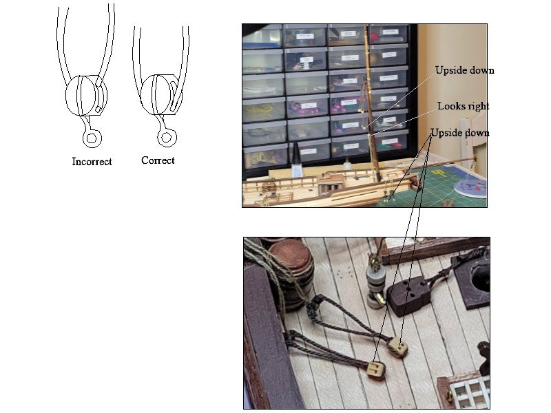
Hi Ken, VERY neat work! One comment/question, hope that is OK. It may be me or the photos are not clear, but your blocks look to be mostly upside down. Allan
-
Doug, I have had the extremely good fortune of having mentors in various areas of this hobby for many years that have guided and taught me. Each of them is a member here at MSW so you are in a good place as everyone seems to be happy to share their own knowledge and experience. Forgotten things??? My memory sucks so a good library is also extremely helpful. Some folks here have hundreds of books but personally I have far fewer in total and find that I only use about a dozen of them on a regular basis. Allan
-
PIllars
allanyed replied to allanyed's topic in Building, Framing, Planking and plating a ships hull and deck
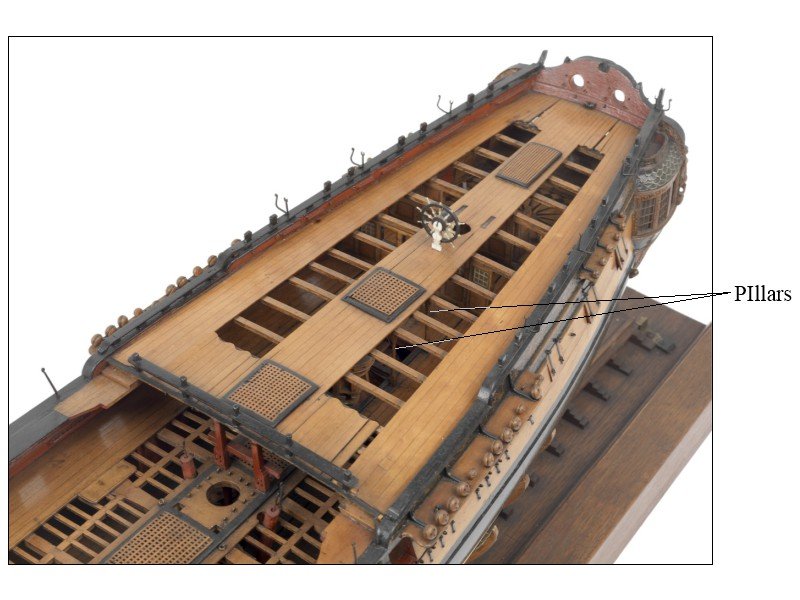
Thanks Mark What I recall seeing is mostly see single row for the orlop and double rows on decks with a larger number of hatches as well as ordnance. Barring anything more concrete that is the route I am going on this experimental project. At 1:200 scale a lot of details are being left out or simplified but the pillar rows can be seen thus my desire to do a little research into it. Allan -
Hi Bob, Glad to see another member join the spiled planking club and avoid the completely unrealistic and poorly done planking designs seen in many kits. Allan
-
Why do you say this? The rope on on the left looks like cable laid rope which was commonly used on stays, preventer stays et al. The quality looks typical of many kit manufacturers, that is, it's horrible, but the twist does seem to be OK depending on where it is to be used. Thanks Allan
-
Huge welcome to MSW Mango! Allan
-
There are pillars between decks and I have found scantlings for them circa 1800 in Steel as well as the Establishments, but what I cannot find, so far, is if they are in a single row or double row depending on the deck. What I need at this point is specifically for a 32 gun, mid to late 18th century. I can see a double row of pillars in the photo below under the QD but cannot find information on the pillars under the upper deck beams. I did look at quite a few inboard profile drawings of 32s and similar size vessels but none of the ones I researched show any pillars on the plans. Any help would be appreciated finding a book or other source that gives specifics or even general information on pillars on various size vessels. At this point I am assuming a double row would be appropriate for the UD but would love to see more information based on contemporary sources. TIA Allan
-
Thanks Roger, much appreciated. Now, anyone have any suggestions for exceptional restaurants? If they have kidneys on the menu, I'm in!!!
-
Thanks Ken! Great suggestions all!!! We were considering MSM, as it is one of the places that is still on the France bucket list. Thanks again Allan
-
Hi Doug, If you want to replicate treenails, which would be wood on Bounty, and have it look like it is fully framed, figure at least 5000-6000. If you plan only to treenail the few frames from the kit, maybe consider leaving them off. No matter what you decide to do SUBTLETY is key. They should be barely visible otherwise it will look like so many of the models we see that look like they have a very severe case of acne. Metal is inappropriate, but making wooden treenails is not difficult and various methods have been discussed at length recently here at MSW including using draw plates and hypodermic needles as drills. Allan
-
Welcome to you up there in big sky country. Allan
-
Ordinarily, "modern" vessels are not my cup of tea, but as I am reading D-Day, 6th of June by Stephen Ambrose once again in preparation for our second visit to Normandy next spring, your build log has been of special interest to me. I have gotten a much better feeling of the design and size of these vessels from your work and thank you for posting the many fine photos. This trip will include Carentan, Caen, St. Mere Eglise, and hopefully a couple other pertinent towns in Calvados next spring. If you (or anyone here) has spent at least a few days in the landing areas, suggestions on "whats and wheres" from hotels to restaurants would be great. Any other book suggestions would also be welcome. The only other ones I have read that cover D-Day are E Company, 506th Regiment, 101st Airborne by Ambrose and The Longest Day by Cornelius Ryan. Allan
-
Penfold, Thank you for the compliment. 😀 Allan
-
Penfold The short answer is that ordinarily you would not see the name anywhere on a Royal Navy vessel until more modern times. The Admiralty did not allow names on their vessels with the exception of between 1780 and 1790. I have seen two or three contemporary models outside this time period, including the Bellona 1760 that did in fact have a name on the counter. Presumably not having the name had to do with minimizing information available to enemy nations. As she was built as a Cherokee-class 10 gun brig sloop for the Royal Navy perhaps Beagle, while not a warship in later years, continued to follow this edict throughout her life. I realize we see a number of kits that have names on the stern, but with the exception of that 10 year span this was not normally the case in real life. Note that when they were on the stern they were painted (not carved letters) and usually, if not always, on the upper counter which are part of the stern timbers. There were also specifications on the sizes of the letters that varied over that 10 year period. Allan
-
It is great to see someone like yourself wanting to delve deeply into the history of the vessel and do a lot of research! One of the great things about selecting this particular vessel, is that you have the 10 very detailed contemporary plans available at RMG from when she was converted to a research vessel so you can make sure the kit got it right or fix things if they got something wrong. Have you found many/any differences between the contemporary plans at RMG and the kit version of Terror? Allan
-
There has been some recent discussion on the out of stock booklet on sail making by David Antscherl. For anyone wanting properly scaled good looking sails that will enhance the model rather than degrading it like most kit supplied sails do, this booklet is now available again from SeaWatch books for $5 on line. https://seawatchbooks.com/products/swan-iv-sail-making-supplement-from-the-revised-and-expanded-edition-by-david-antscherl?_pos=1&_sid=aafd9ea69&_ss=r
-
Where to find a copy of Antscherls sail making
allanyed replied to src's topic in Masting, rigging and sails
Hi Sam, The new owner at SeaWatch is working on getting sold-out books back into stock but I am not sure which ones are included as there are minimum runs to consider with the printers. Did you contact SeaWatch to ask if there will be reprints coming? Allan -
Druxey LOL!!!! I needed a good laugh, many thanks for that!!!
-
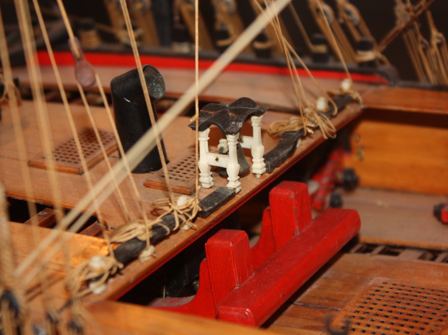
Gregory Good catch!! I don't recall ever seeing mitered joints on the head ledges and coamings on a contemporary model. Could it be these are replacements from some later date? Either way, they do not seem to be made using accepted practice for that time. Allan
-
Looking at contemporary models at Preble Hall and RMG for late 18th century ships, all of the gratings are wood. One example is below. Does this mean it is the same on Unite? Not necessarily, but you cannot be faulted for using wood as this is at least one example that shows wood gratings were used. For Unite, it sounds like you have the contemporary plans (ZAZ3183) and as refitted (ZAZ3184) from RMG. Kudos on doing the research!! Allan

-
Have you tried following the methods in the tutorial A Primer on Planking in the MSW articles data base by David Antscherl? Allan
-
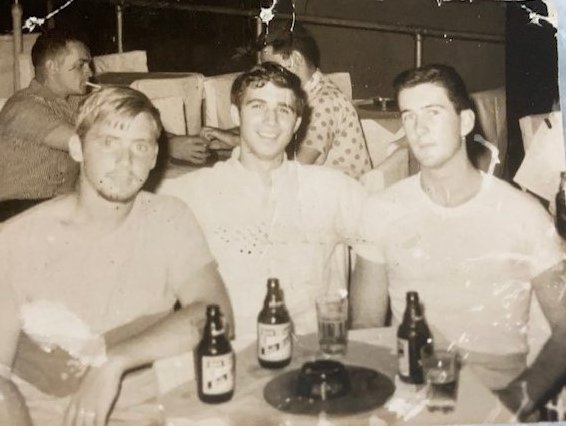
Hi Kale, Super happy to see a youngster join and make a very wise choice on his first endeavors! I would love to visit your country again one day, been a long time since I was there. (55 years) I have fond memories of a nice little bar in Olongapo with a couple shipmates from the SS Pioneer Myth and bottles of San Miguel beer. . (Pic below, me in the middle) Allan