


VitusBering
-
Posts
297 -
Joined
-
Last visited
Content Type
Profiles
Forums
Gallery
Events
Everything posted by VitusBering
-

Helping hands troubles
VitusBering replied to VitusBering's topic in Modeling tools and Workshop Equipment
I think I agree with you Roger. That's almost the idea behind the ball-joint Helping Hands, it is secured against moderate forces when the thumbscrews are tightened. -
Helping hands troubles
VitusBering replied to VitusBering's topic in Modeling tools and Workshop Equipment
Here's my problem... -
Helping hands troubles
VitusBering replied to VitusBering's topic in Modeling tools and Workshop Equipment
Thanks for the replies, folks. Maybe I got a borked set. I'll get a third-party set to see how that goes. I retrieved my arms from the bin, they hadn't been collected yet. I'll post a video illustrating the problem to see if I'm being unreasonable. That's entirely possible. -
I'm currently using the QuadHands Workbench and I have to say I hate it. How this thing gets so highly rated is completely beyond me. The arms have a horrible amount of springback, making it impossible to align parts to be soldered or glued or whatever. It is very frustrating. To make matters worse, the magnets on the arm bases are quite strong. You would think this is a good selling point and it would be except that the arm bases have a foot that prevents the arm from moving unless a great force is applied and then the arm moves suddenly past the point it was supposed to. The only thing good I can say about this mess of a product is that the powder coating on the base is nice. I've already tossed out the worthless arms and shopped around for a third-party replacement but reviews for those cite the same springback problem. My trusty old ball-jointed solid-arm Helping Hands worked well with a few minor annoyances (like limited distance between claws and having to lock the joints). I would rather have a flexible solution but so far I cannot find a single one that doesn't have the springback problem, according to reviews. Do any of you folks have any experience with these things and can recommend one to me?
-
Awesome work and I totally agree the deck wood (and the rest too) looks fantastic.
- 56 replies
-
- 4
-

-

-
- Sea of Galilee Boat
- SE Miller
- (and 1 more)
-
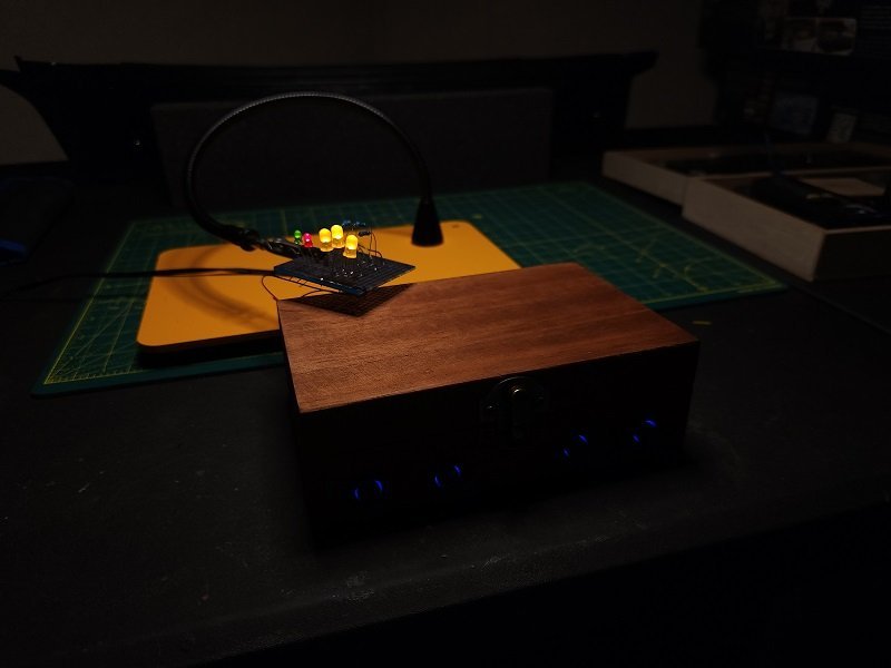
Thanks folks, I truly am champing at the bit here... but it does give me a chance to futz around more. After testing in a mockup rig, I've reduced the output voltage on all regulators to 3.3 volts, and increased the resistance on the red LED to balance brightness with the green. I'm fairly happy with the result. I had to set the ISO on my camera to 100 and the speed to 1/180, otherwise the LEDs look like phosphorus flares. [edit] A couple of extra notes. I was remiss in not thanking DanielD for cluing me in on the complexities of USB-C connections and linking to a wonderful concise solution. So thank you Daniel! Also you all know that one my biggest gripes about my previous build (if I ignore all of the fatal mistakes I made in construction) was those horrendous Revell paint colors. I've received a big variety of Vallejo paints including every shade of brown they make. Now that I've gone as far as I can with the lighting for a time, I'm going to test and compare all of these new paints. Another edit - I got the pinouts sorted and now the connector is permanently installed in the control box. I haven't started on the hull yet, I'm still awaiting delivery of the wooden deck, nav lamps, windows, hearts and other blocks, more brass stanchions and belaying pins, and more rope. That will all arrive in one swell foop from HiSModel. When, though, is a matter for conjecture. Radimir did say it could take a couple of weeks - a couple of weeks ago ;-} I will leave him alone for another week, I'll ping him if I haven't heard anything by then.
- 89 replies
-
- 2
-
-
- Cutty Sark
- Revell
- (and 2 more)
-
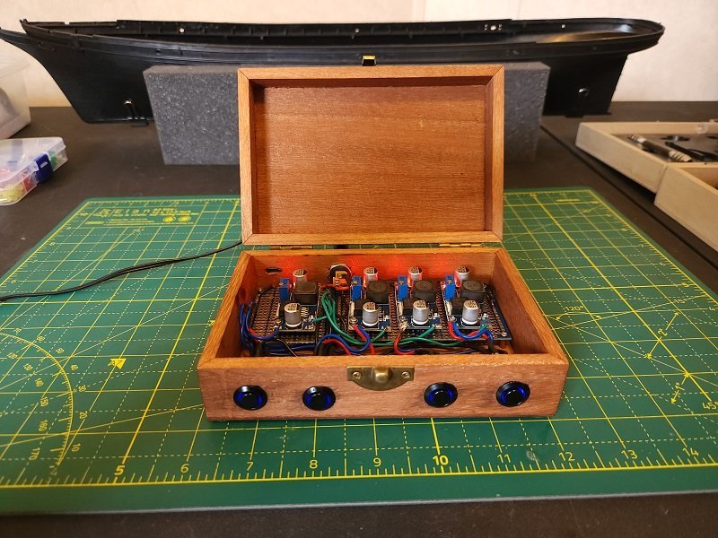
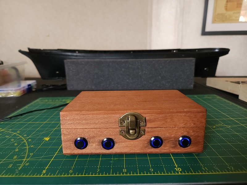
Well, I have been lurking here and meddling in others' build logs for quite some time. Most of you know I abandoned my previous Cutty Sark build and I'm very anxious to start anew. I have the kits (one as a working kit, the other is spare) and almost all of the necessary extras. However, I'm still awaiting one more delivery consisting of a wood deck, windows, rope and a few other accessories. They're coming from Radimir at HiSModel in the Czech Republic and, though he's a bit late, I am confident they will arrive soon. Until they do, I have finished the control box for the lighting. The lighting will consist of navigation (running) lights and interior illumination of the three deck houses. Power is a 12-volt 2-amp wall wart that plugs into a socket in the back. Output voltage is currently set at 6 volts for each regulator. I haven't installed the box-to-ship connectors yet, I need to determine the pinouts and that's a tedious process. The wood is very soft so I have some tearout from the drill but not enough to make me do it over. I may make another one in hardwood at some future time. I debated with the boss over labels for the switches and she won out (she always does). They're not really necessary and detract from the aesthetic.
- 89 replies
-
- 6
-
-
- Cutty Sark
- Revell
- (and 2 more)
-
I apologize for jumping in here - I am not sure where Daniel got his lamps but I get mine from RB Model. There are several styles and sizes of lamps here - some have LEDs, others do not. When you highlight a particular lamp style, if the "Additional Info" button is available, then that lamp probably has an associated LED. If the Quantity column has a "0 pieces" entry for a particular size, that size is unavailable.
-
Beautifully crafted.
-
Marvin is priceless, and I'm glad you didn't use his Illudium Q-36 Explosive Space Modulator. Mjölnir is a tack-hammer compared to that thing. The hull looks really good.
- 56 replies
-
- 7
-
-
-

-
- Sea of Galilee Boat
- SE Miller
- (and 1 more)
-
Amazing work and very inspirational. The detail is phenomenal. I hope to start on my own soon - still awaiting parts from the Czech Republic and elsewhere.
- 444 replies
-
- 1
-
-
- Cutty Sark
- Revell
- (and 2 more)
-
Удачи! Обязательно создайте журнал сборки, когда начнете, мы будем рады увидеть вашу работу. Я планирую начать свой собственный (комплект Revell) очень скоро.
- 47 replies
-
- 2
-
-
- Cutty Sark
- Artesania Latina
- (and 1 more)
-
If you check out articles on the Piper Cub (the landing gear suspension on that venerable workhorse is literally bunjee cord) you can find articles on the positive camber angle. The gear spreads a bit when the balloon tires hit the runway.
-
Plastic or Wood models? Your Favorite?
VitusBering replied to Bill97's topic in Modeling tools and Workshop Equipment
I'm still fighting the urge to pull the trigger on the Model Airways Curtiss JN - 4D Jenny. I have a Cutty Sark waiting on a veneer deck and a few other accessories that promises to take all my time, and an unopened sports car on the shelf. I have absolutely no business even drooling over that kit but it is invading my dreams. That catalog is evil. Deliciously evil. -
Matt Clear Coat
VitusBering replied to aliluke's topic in Painting, finishing and weathering products and techniques
Vallejo has several different matte varnishes - I've only used the Mecha Matte version. In my experience that varnish finished in a nice matte but wasn't quite as dulling as the AK. They're both good products, I simply prefer the AK and I believe (though I can't prove) that the AK has less of a silky finish than the Vallejo. That being said I have not tried them side by side so that is a purely subjective opinion. Again, they're both good products. -
Matt Clear Coat
VitusBering replied to aliluke's topic in Painting, finishing and weathering products and techniques
The stellar reviews on this are spot on. It dries in a truly matte finish. It will knock the shine off of any painted object. AK Interactive Ultra Matte Varnish I get mine from Megahobby, the AK store also carries it, of course, and it is also available on Amazon. https://www.megahobby.com/products/ultra-matte-varnish-60ml-bottle-ak-interactive.html -
On my dear departed Cutty Sark I installed the brass stanchions with their holes aligned in the angle of the through cable (thread, in my case). I used a map pin through one of the holes to align the stanchion at the proper angle as they were set in place. I agree with Harry about monofilament, that stuff is awful.
-
I should have mentioned that in my post. Great minds think alike. I do intend to use a data cable and map the connections using a multimeter. Of course, I don't care about the "real" intended use of the pins. I may well use the the device you listed above in the switch box, and maybe in the hull. I have ordered a couple of them, to have on hand in addition to the ones I planned to mangle. Which one(s) I use is to be determined. Thank you very much again. Your build is looking fantastic. [edit] totally off-topic but this all brings back a flood of memories from a time before time when I did tech support. I still remember the RS-232 null cable pinout of 2->3, 3->2, 6 to 8 and 20. I wish I didn't remember 🙂
-
That does look nice. Thanks for the tip!
-
I intend to mount the voltage regulators on one of these project boards. I'll put that board in a nifty little wooden box and mount the switches, power connector for the 12v wall wart, and the usb connector in and on the box as well. Some of the components I need (standoffs and shrink tubing) are still in transit. I really dislike being at the mercy of online shopping but I do love this home and area despite the remoteness. When it is all together (probably a couple of weeks or so) I'll post a pic or two. Thanks again for the tips on the regulators and LEDs, they're working out really well - my test circuits have great results - I adjusted the resistance on the different colors to get a good brightness balance with a nominal 3v supply. The led set came with an astonishing array of resistors of just about any value I could ever need and way more leds than I can ever use - but my better half wants to light up her Christmas cottages so it is a good thing I got a good supply of those regulators - there is probably a honey-do in the offing.
-
The one I chose is a cable with male and female ends. I'll get a couple of them and cut the cables. I plan to put a female end in the hull and another in the switch box. Then any male-to-male usb cable should work to connect the two. I don't know how many wires are in each cable but there should be more than nine. I chose this one because the female end is easily mounted and mostly concealable in the hull side or bottom. Wow, this is a long URL, sorry for that. https://www.amazon.com/AAOTOKK-3-1Panel-Adapter-Supports-Charging/dp/B08HS6X44P/ref=sr_1_19?crid=32MH4NKZQ565G&keywords=aaotokk+90+degree+usb+3.1+type+c+cable&qid=1682909240&sprefix=AAOTOKK+USB+Type+C%2Caps%2C104&sr=8-19 [edit] I did find a few examples of bare connectors but they didn't have a convenient way of mounting them except on a PCB.
-
Yes. I added a paint color to a cart and pressed the calculate shipping cost button and the US (and specific State) were options in the list.
