JacquesCousteau
-
Posts
1,362 -
Joined
-
Last visited
Content Type
Profiles
Forums
Gallery
Events
Everything posted by JacquesCousteau
-
 Congratulations, what a great build! Excellent eye for detail on the drying sand and the barge floating low. It's been very fun to follow along, and a good reminder of just how much detail you can fit at even a tiny scale.
- 457 replies
-
- 3
-

-

-
- sternwheeler
- Hard Coal Navy
- (and 1 more)
-
Tricky though it may be, it looks like you're doing a good job of it! I think I used wedges made from scrap, rubber bands, and bobby pins to hold things in place toward the end. Same! I suppose books of modeling techniques were also more useful for beginners then, but they can only do so much. Without this forum, I certainly would have a much harder time, and I doubt I would have started in the first place.
- 24 replies
-
- 2
-
-
- maine peapod
- midwest products
- (and 1 more)
-
Nice work! I also built my peapod model while I had other builds going. All those thin planks are pretty tedious to add, although I suppose using superglue might make it faster? I also remember finding it a bit tricky to avoid a clinkering effect going around the turn of the bilge.
- 24 replies
-
- 2
-
-
- maine peapod
- midwest products
- (and 1 more)
-
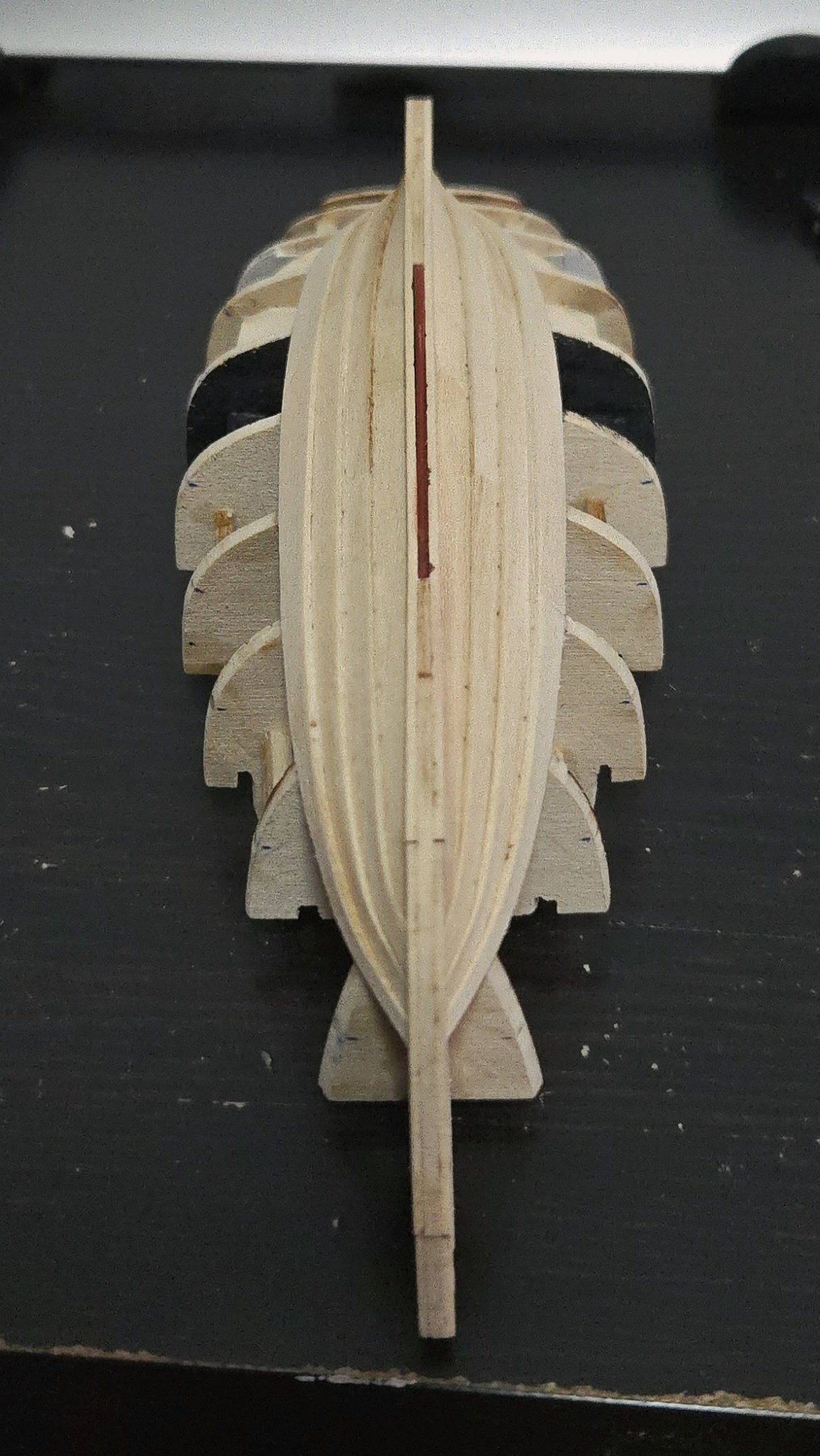
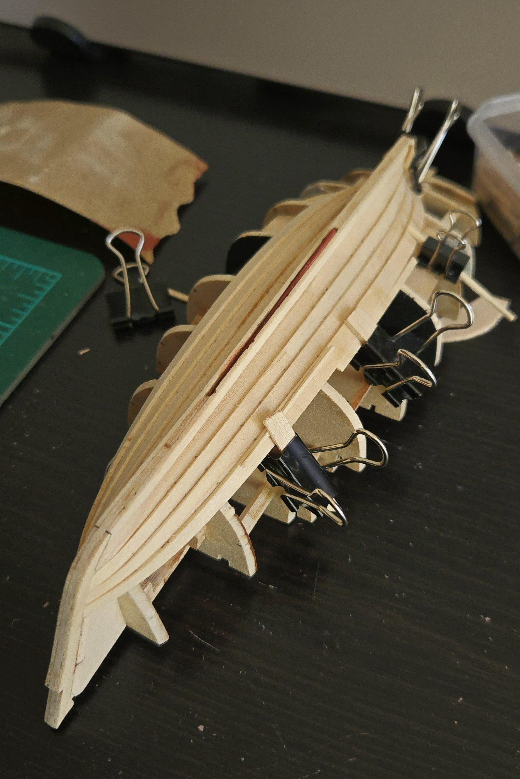
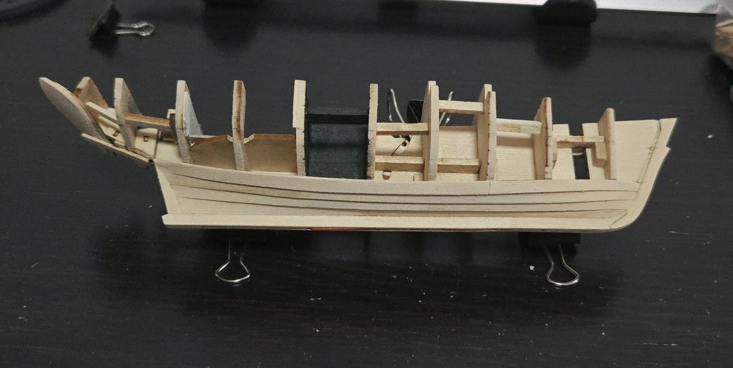
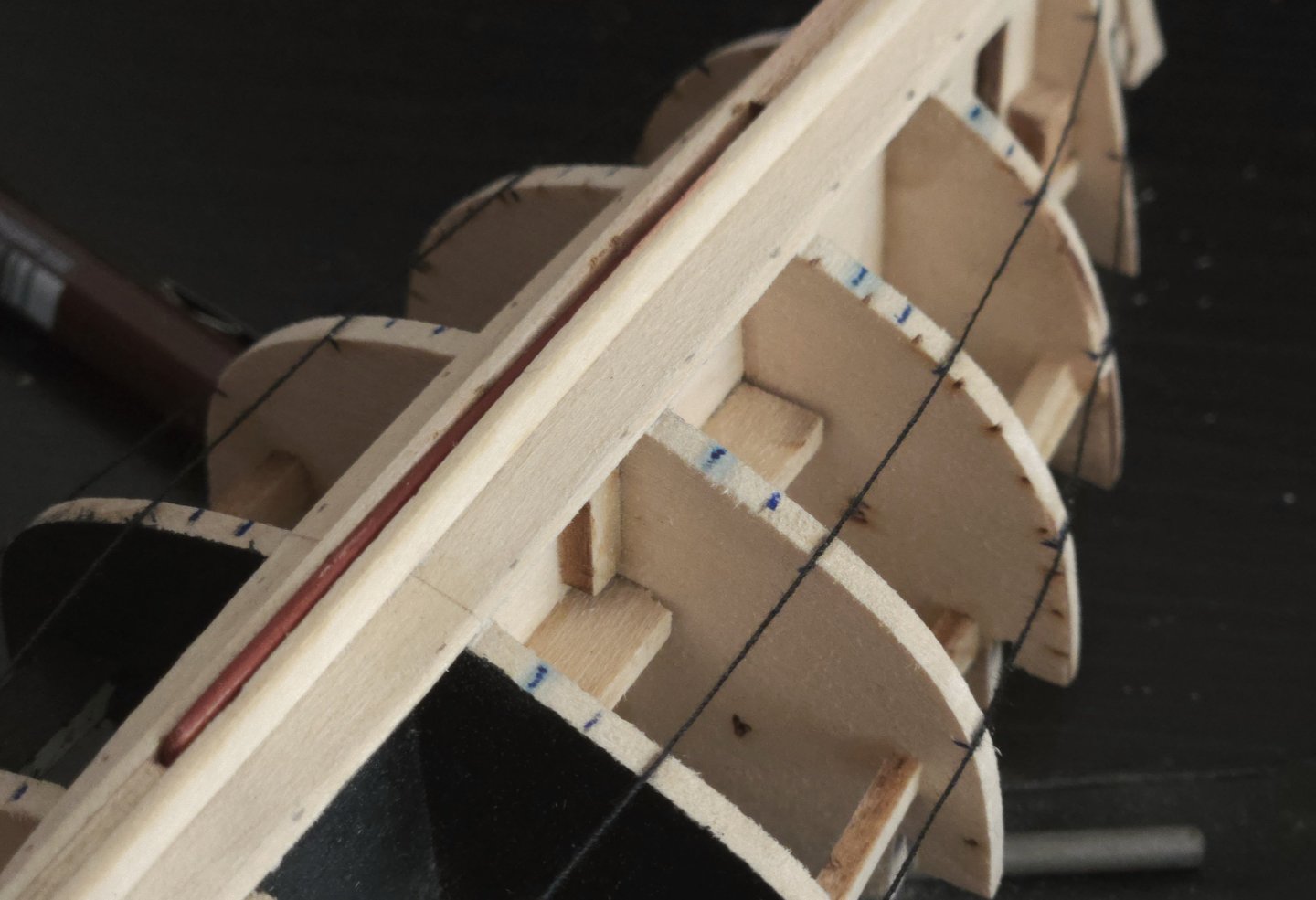
Thanks, all! I've now finished the first band of planking. This has, as always, been a slow process--tracing templates on tape, cutting out the plank, adjusting to fit, soaking it and letting it dry in shape, fine-tuning, and gluing--but an enjoyable one. Although I've fit four planks where the kit design has three, the required plank overlap means that my planks have often been about the same width or slightly wider than the kit-designed planks. I've been able to use some segments of kit-designed planks where they match what I need, but I had to cut a lot of them myself. Overall, lapstrake planking has been an interesting experience with its own challenges. I've had a tricky time getting good tape templates for the planks, as the tape isn't running flat from upper to lower edge of the plank shape, but runs along the bulkhead, abruptly shifts up onto the lower plank, and continues to where I've marked the lower edge. It's also been difficult to properly shape the planks for smooth runs. With carvel planking, you can use clamps to push the plank against the lower strake, which can allow you to do a bit if minor edge-bending if necessary. With lapstrake planking, you can't really do that, and have to judge that the plank is placed well and will have a smooth run. As a result, I've often had to adjust the joints between planks afterward with sandpaper. The top edge of the planks are often a bit uneven or off at the joint between planks in each strake, as seen below, where there's a sort of divot in the run of the strake. Thankfully this is easy to cover with the next strake, just making sure to measure the plank's location from the lower edge of the previous plank plank rather than from the upper edge. In any case, today I finished the final plank in the lower band, reaching to the top of the sternpost. From this point on, I think the planks should be easier to bend into shape, as they'll have a lot less twist. Before continuing, I'll need to re-line out the remaining bands and planks. My lower band ended a tiny bit short of the mark amidships, but it's nothing that can't be corrected by slightly adjusting the width of the remaining planks.


-
Nice work! I never would have thought of using that material a base, but it looks great, and from a distance gives the impression of a gray sea.
-
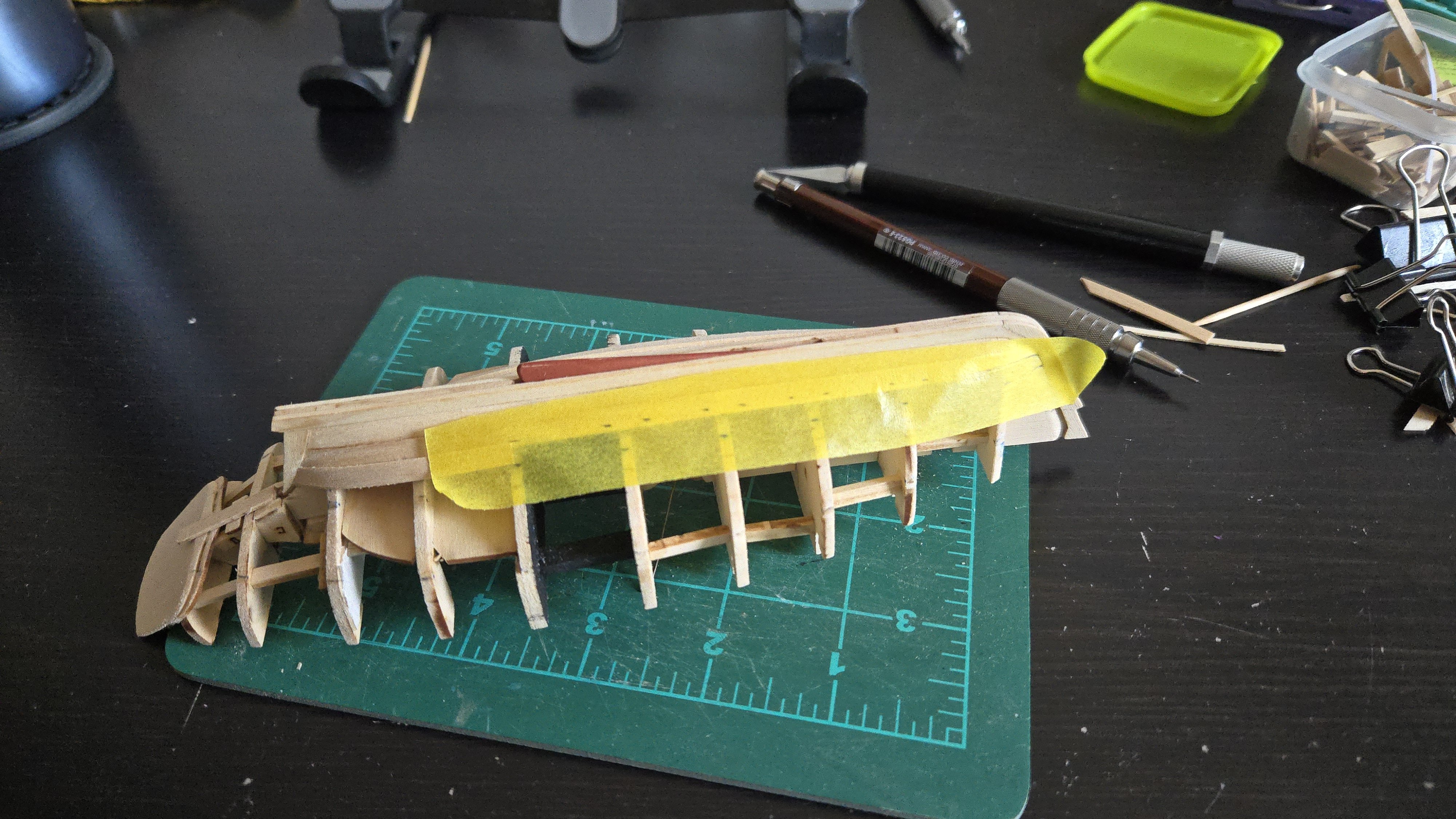
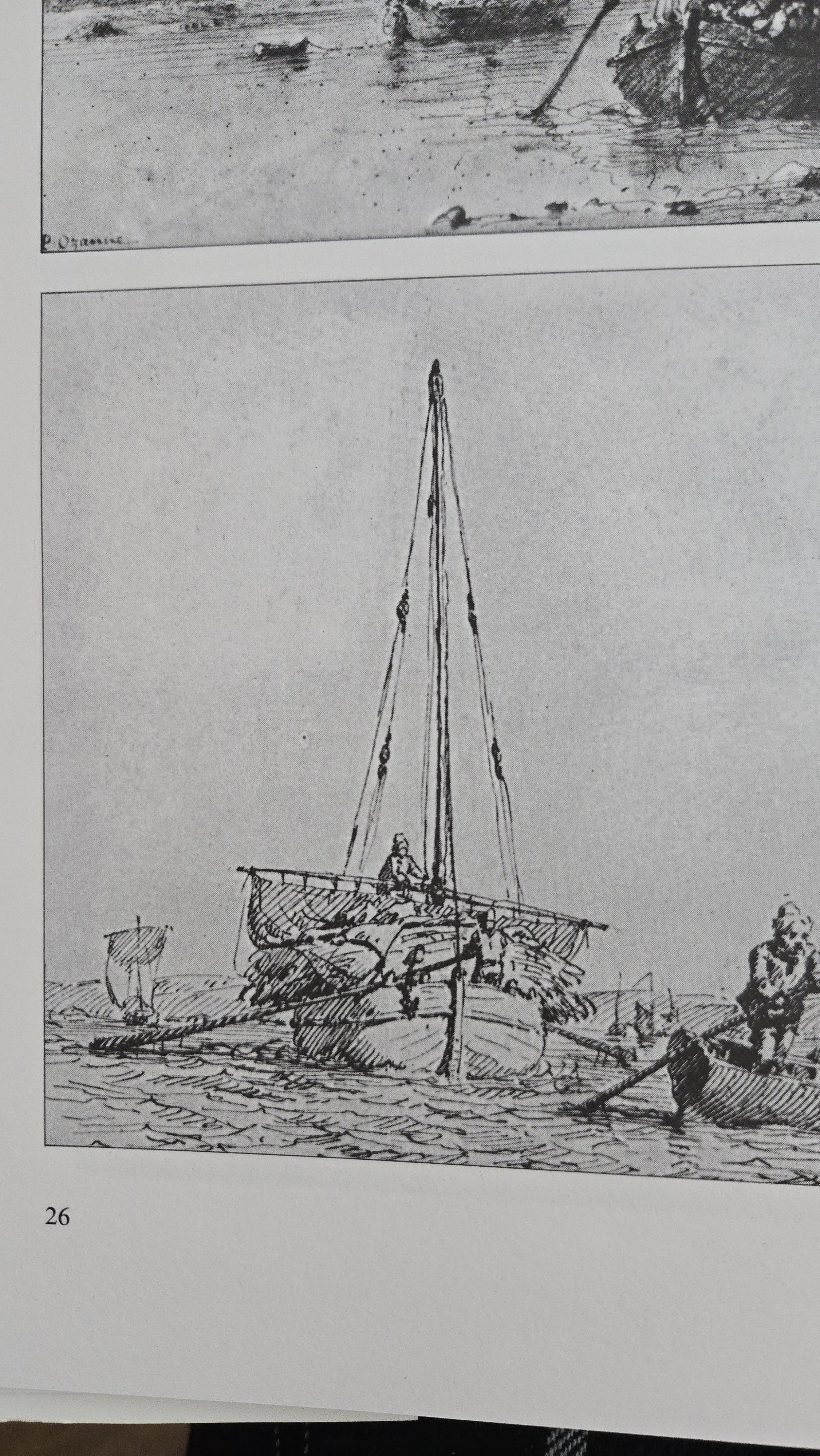
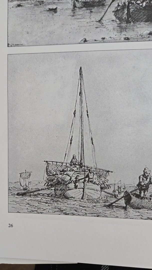
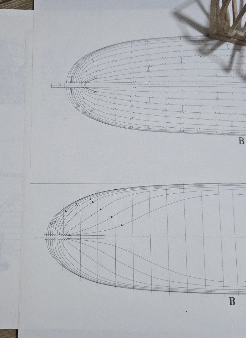
@wefalck, you're right that the planking runs are easier with a slight rise at the ends. The plans show fairly limited rise, but definitely some: Although I didn't find any photos of the type, drawings in the monograph show a bit more than given by the plans. Maybe it's artistic license, but definitely suggestive. In any case, angling the plank (in this case some scrap) a bit leads to a much better run across the frames.

- 139 replies
-
- 9
-
-

-
- ancre
- Bateau de Lanveoc
- (and 2 more)
-
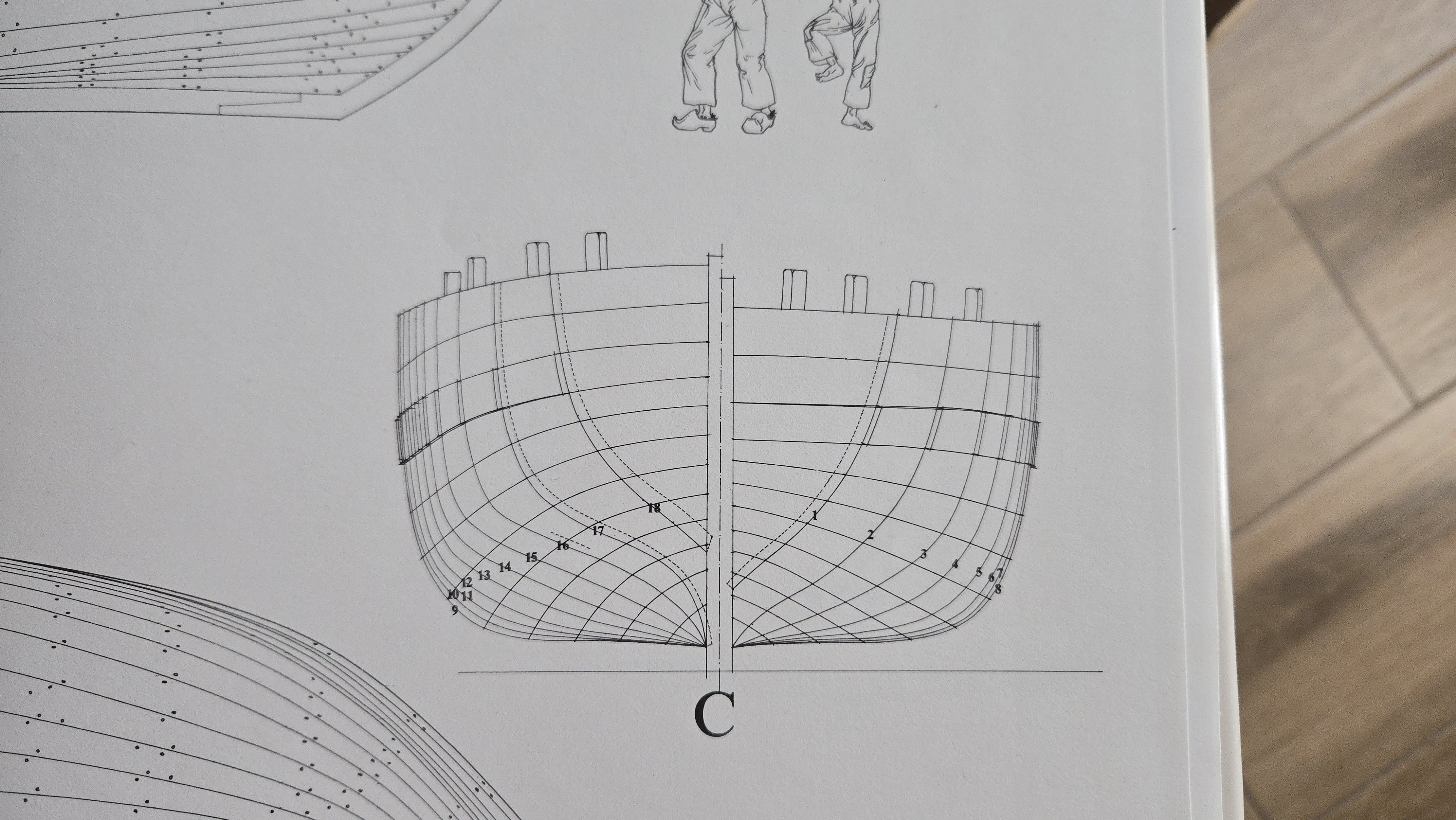
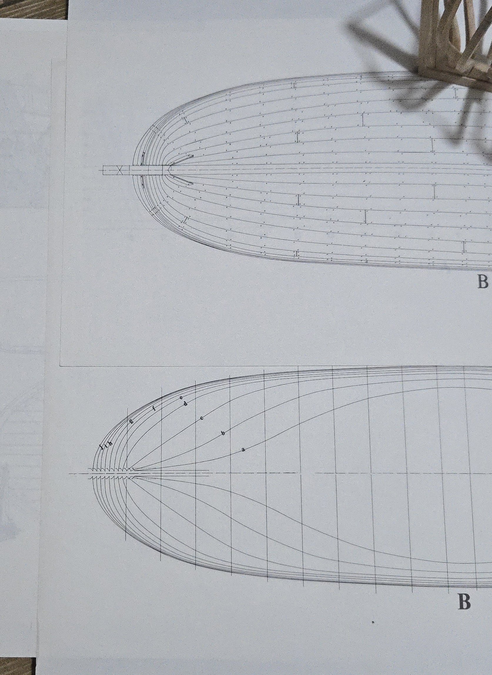
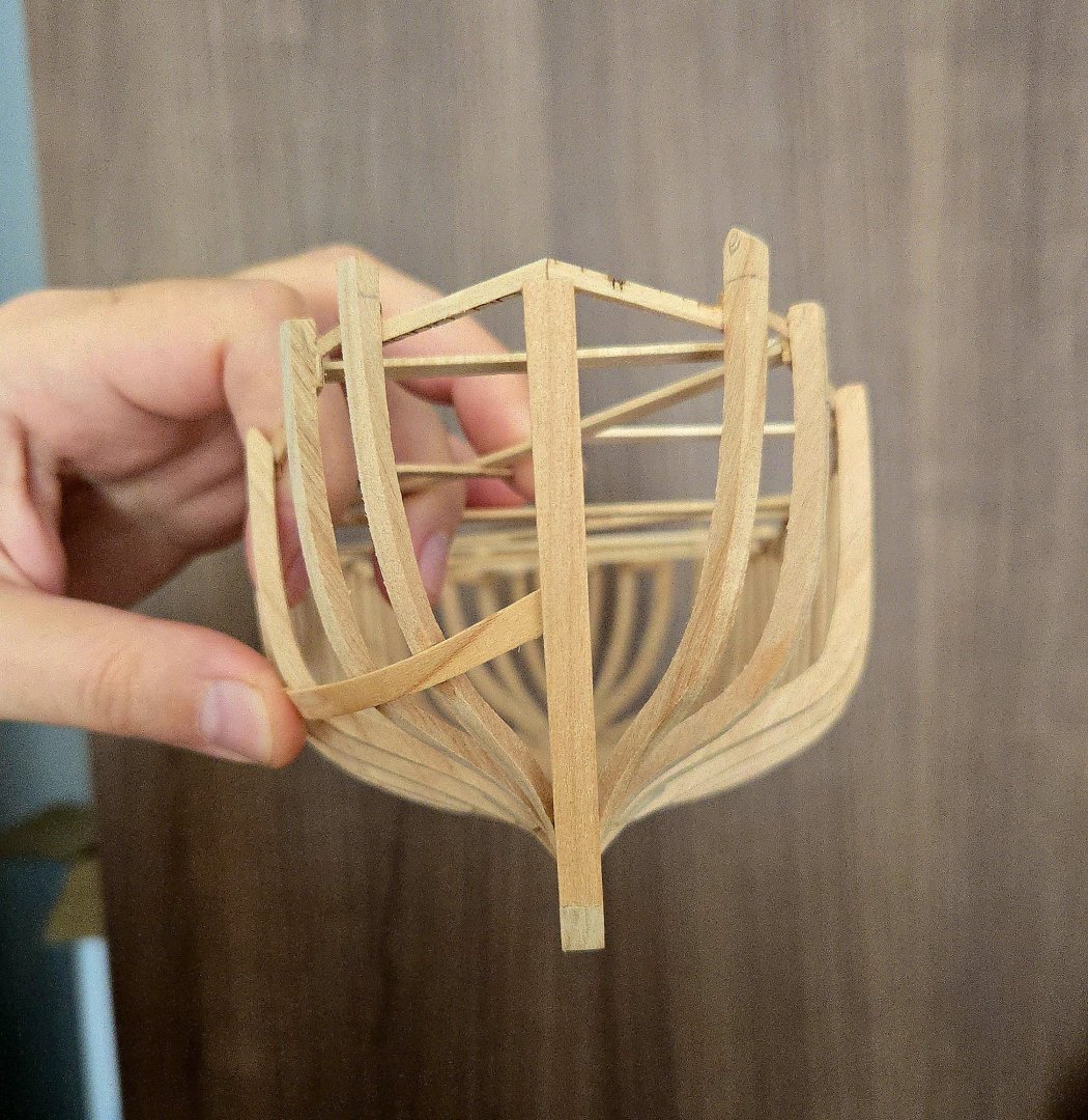
I think that's the trickiest part, I'm still developing an eye for planking and hull shapes and this particular hull form is a bit tricky for me to visualize. It would be an interesting experience to add the cant frames later, either fitting it to the planking or to a run of battens, but I don't think I'll be able to get the sharp bend shown on the plans without a frame in place. I think that I'll try measuring the dimensions of some of the waterlines and comparing them with some of the same points on the model hull to see how well the current frame position matches the plans.
- 139 replies
-
- 4
-
-
- ancre
- Bateau de Lanveoc
- (and 2 more)
-
Nice work! I hadn't noticed this build before, it's a very interesting subject.
-
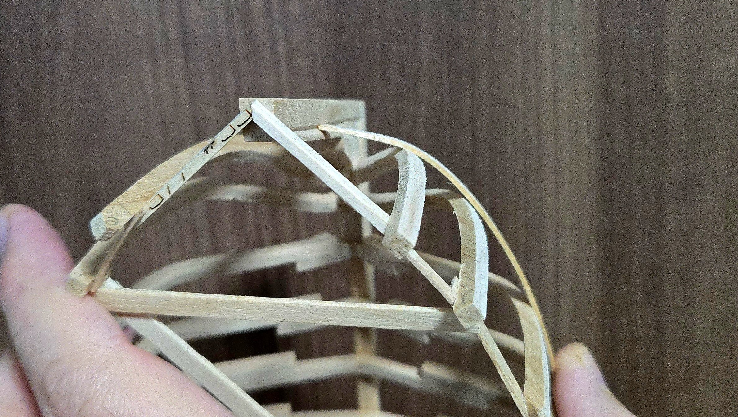
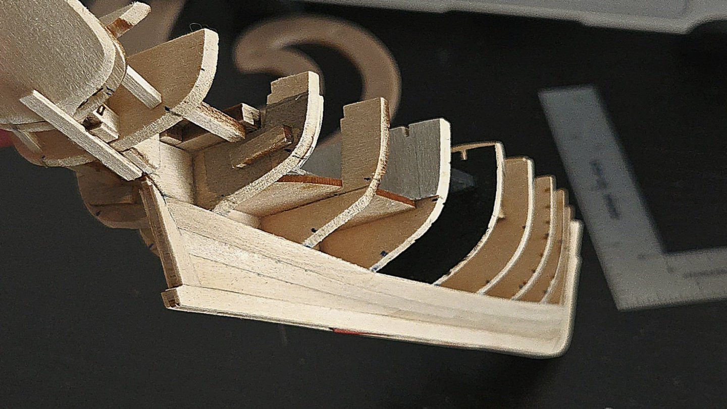
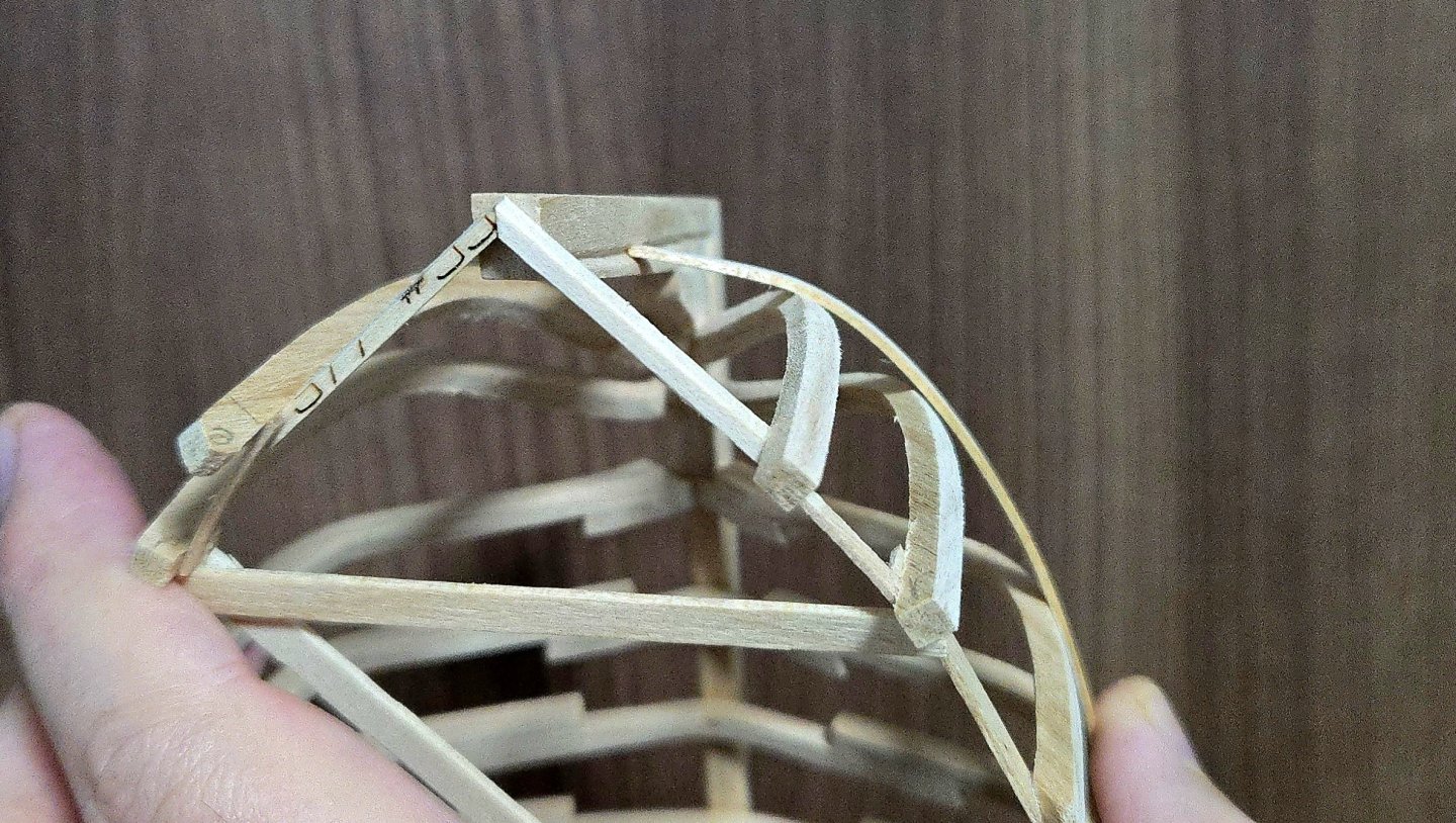
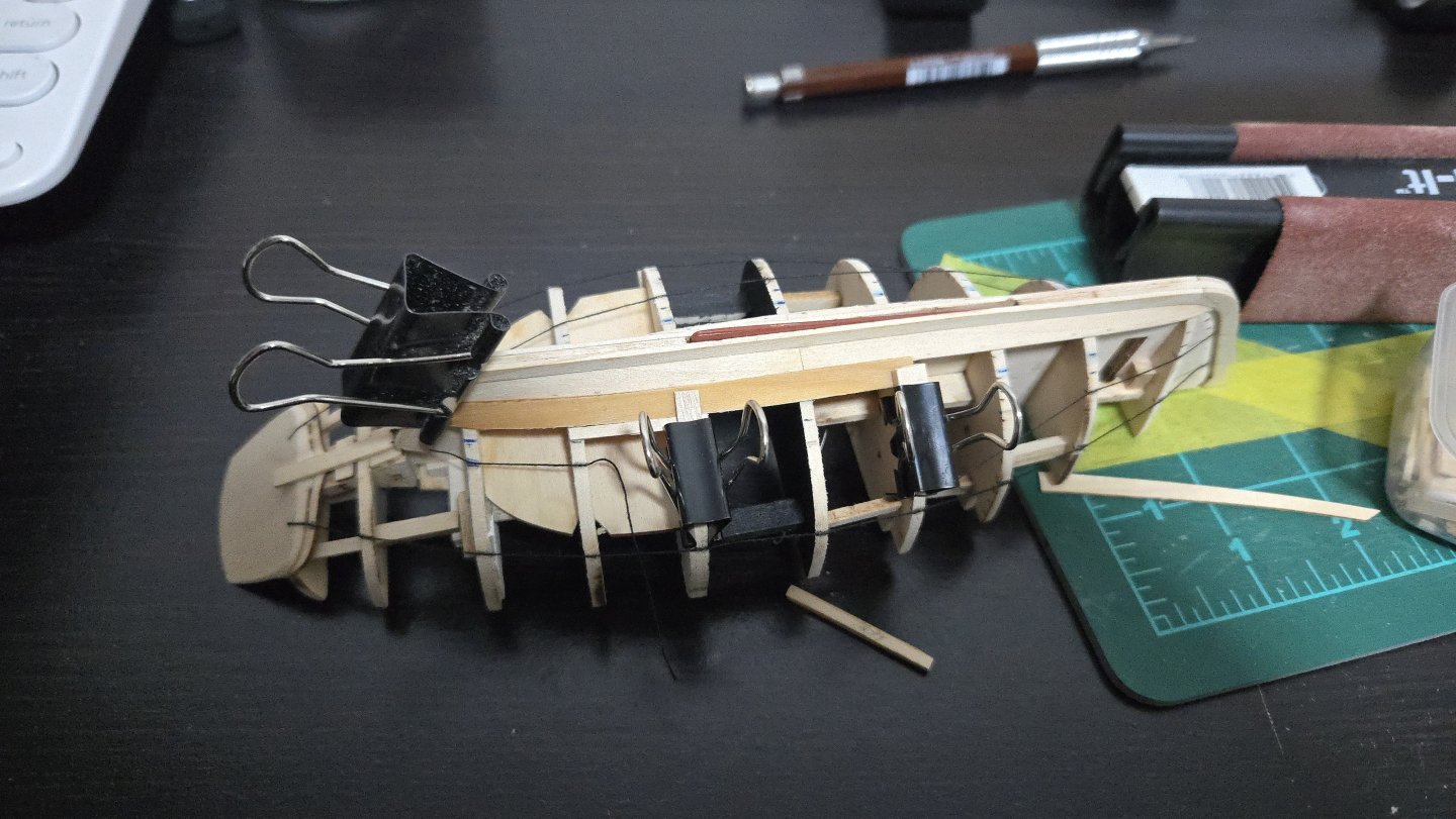
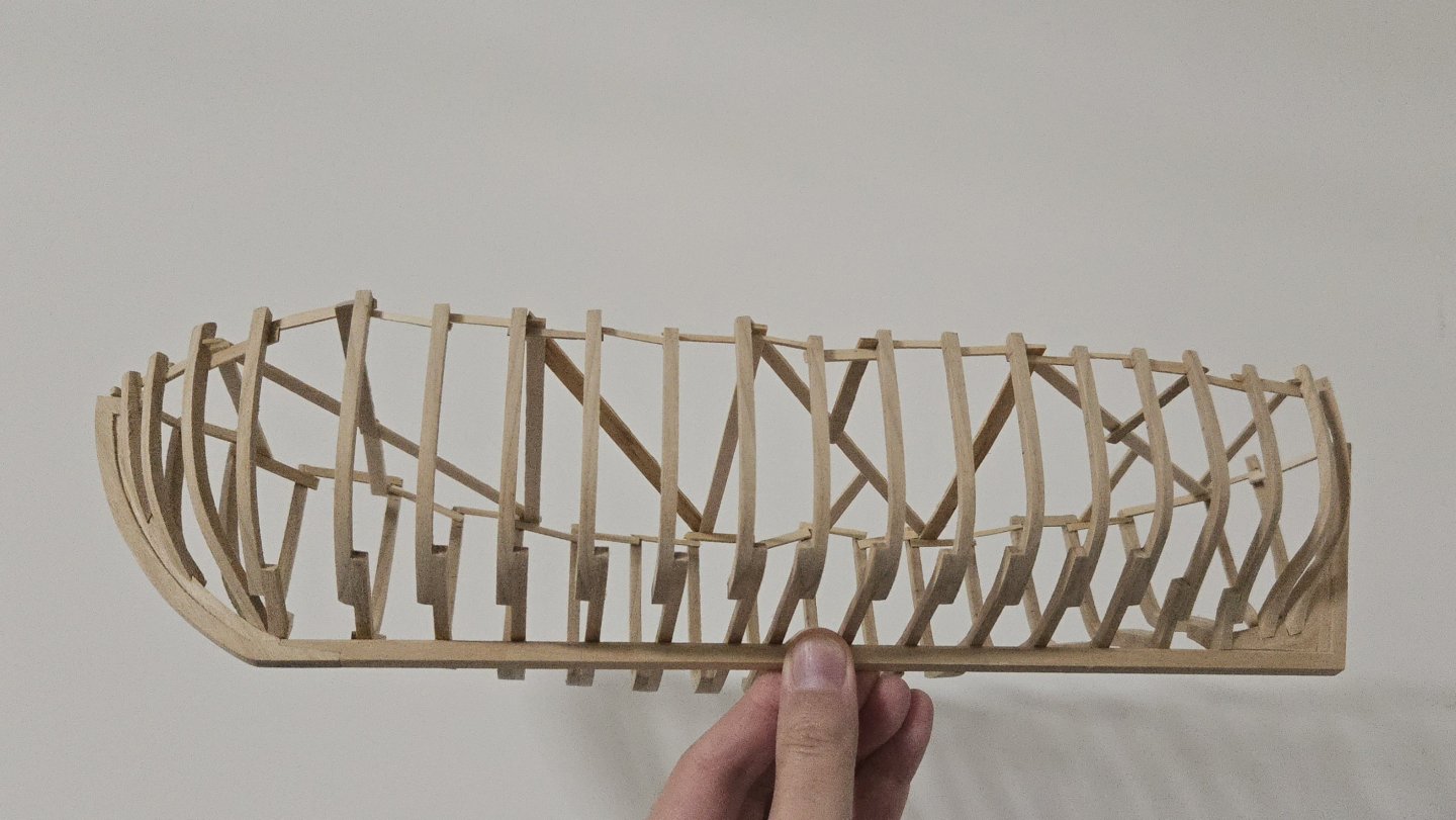
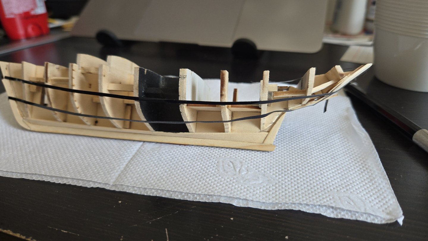
By this point, I think I'm nearly done with fairing... the port side, that is. It's taken a while, but at this point battens seem to run smoothly all along the hull. The main exception is at the stern, where the required bend is so sharp that I can't run battens without them cracking. I had to soak a piece of thin basswood for the photo below, which suggests I have some fine-tuning to do. It's a ridiculously sharp turn, but looking at the plan drawings of the hull lines and the planking runs at the stern, I think it's supposed to be like that? Part of me almost wants to detach the sternmost cant frames and re-glue them slightly higher on the deadwood, but 1) I don't think that would make that much of a difference, and 2) they're already positioned higher than they're supposed to be according to what I can understand from the plans. Trimming a bit off the bottom where they join the deadwood might provide a slightly easier run into the sternpost, but I think this is just a tricky stern to plank regardless.
- 139 replies
-
- 8
-
-
- ancre
- Bateau de Lanveoc
- (and 2 more)
-
Great job! The base is really inventive and turned out well, not to mention the quality of the model. It turned out really sharp. You may have mentioned earlier, but did you apply any finish to the hull exterior? The walrus oiled base may not have turned out to your liking, but I think it contrasts nicely with the lighter hull and map segments.
- 38 replies
-
- 3
-
-
-
- 18th Century Longboat
- Model Shipways
- (and 1 more)
-
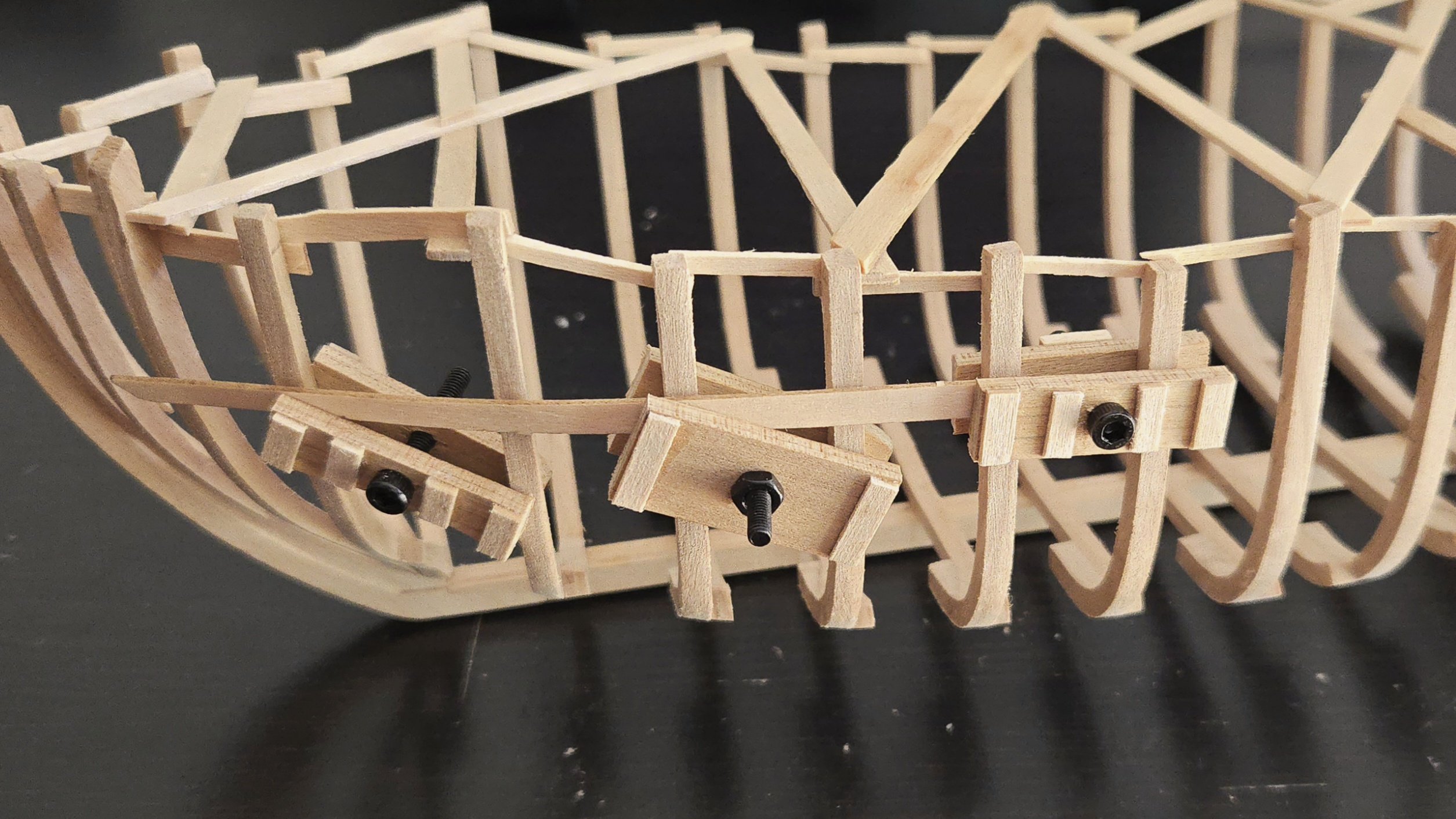
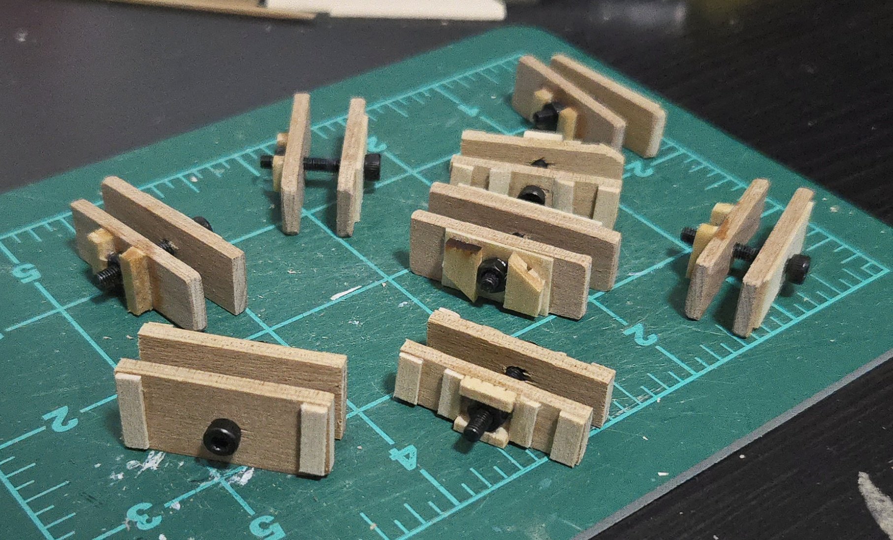
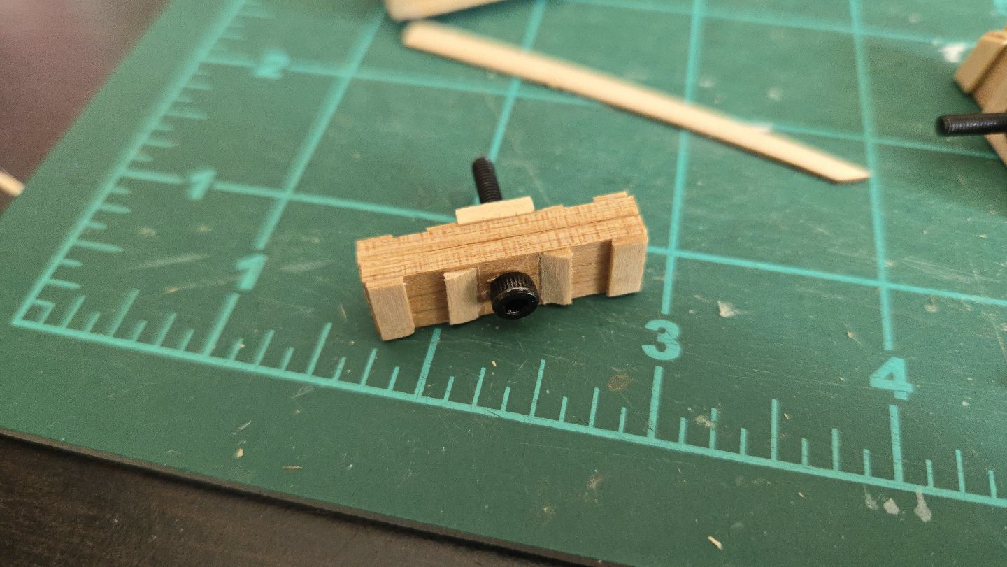
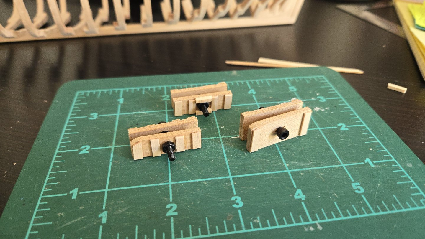
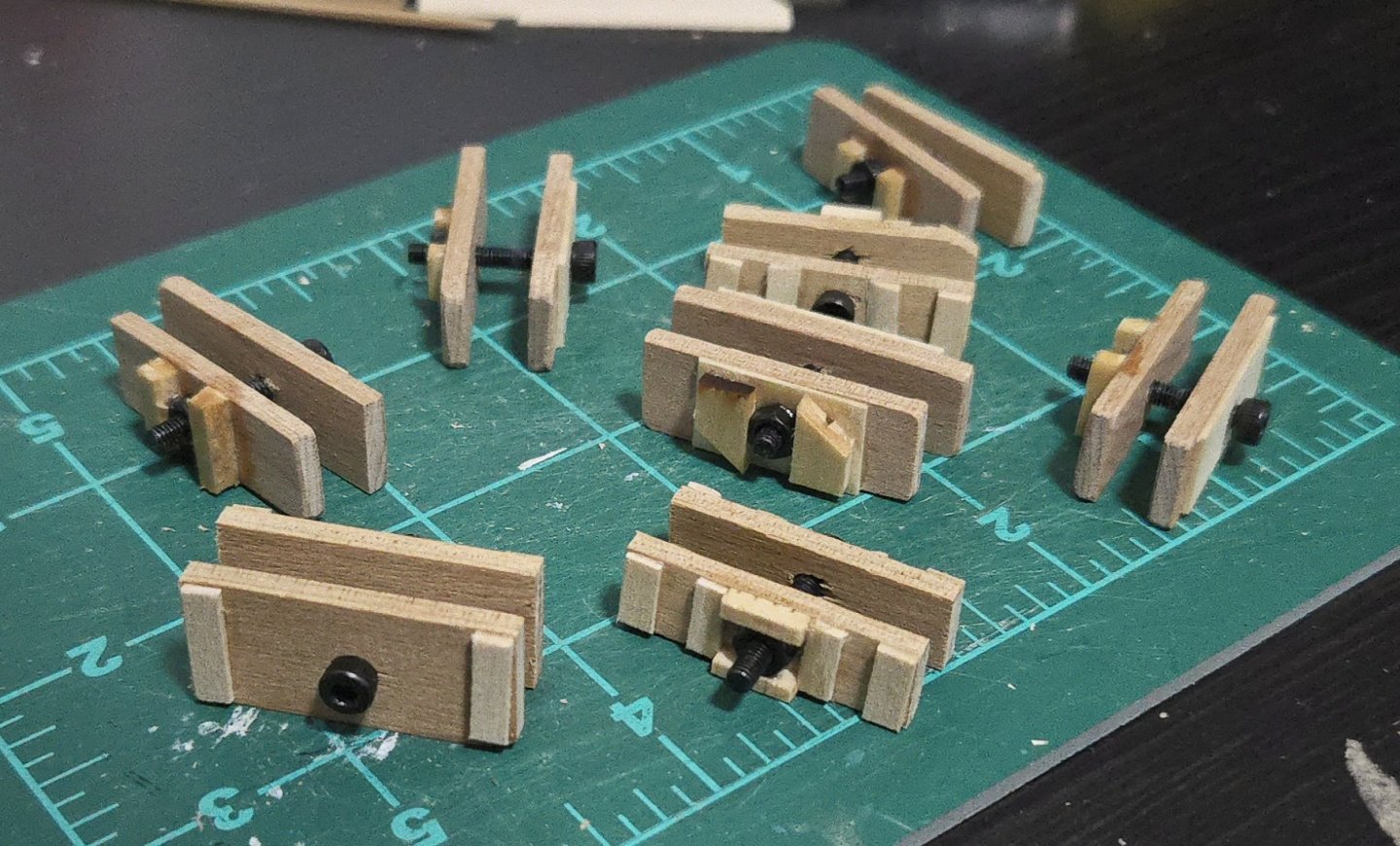
While I'm (slowly) fairing the hull, I also have worked on making some simple clamps for when I get to planking. I realized that the binder clips and clothespins I already had weren't going to work very well. So, I made some simple ones by drilling holes through scrap wood, adding cross-braces to prevent splitting, and running a small nut-bolt combo through it. They're pretty rough around the edges and way less refined than some of the beautiful homemade clamps I've seen in other build logs, but they should be helpful when it comes time to plank After making my first three, I wondered whether it would be a good idea to secure the nut in place so that I wouldn't have to hold both nut and bolt to tighten the clamp. So, as can be seen above, I used super glue, bracing, and some white glue to secure the nut on one clamp. I then tested the three with a scrap plank on the hull, below. I found it much easier to tighten the clamp with the secured nut. So, I modified the others to also secure the nut in place. I also beveled down some of the cross-bracing near the bolt head, shown below, as it was making it difficult to tighten by hand. For the rest of the clamps, I got rid of the multiple cross-braces, in favor of just gluing a piece of basswood across most of the surface of the clamp with the grain running perpendicular to the main piece. At this point, I now have eight clamps, which should be enough, especially as each can clamp on two adjacent frames at once, and they're not hard to make if I need more. It's a very minor update, I know, but I thought it might be useful to see how simple a homemade clamp can be to make.

- 139 replies
-
- 9
-
-
- ancre
- Bateau de Lanveoc
- (and 2 more)
-
Very nice work!
-
Thanks! I'm interested in exploring build techniques that don't use power tools, as I think it's still possible to do a fun build without them. We'll see how the capstan itself turns out, though--I've paused this build for a bit while I consider how to make it.
- 32 replies
-
- 8
-
-
- NRG Capstan
- NRG
- (and 1 more)
-
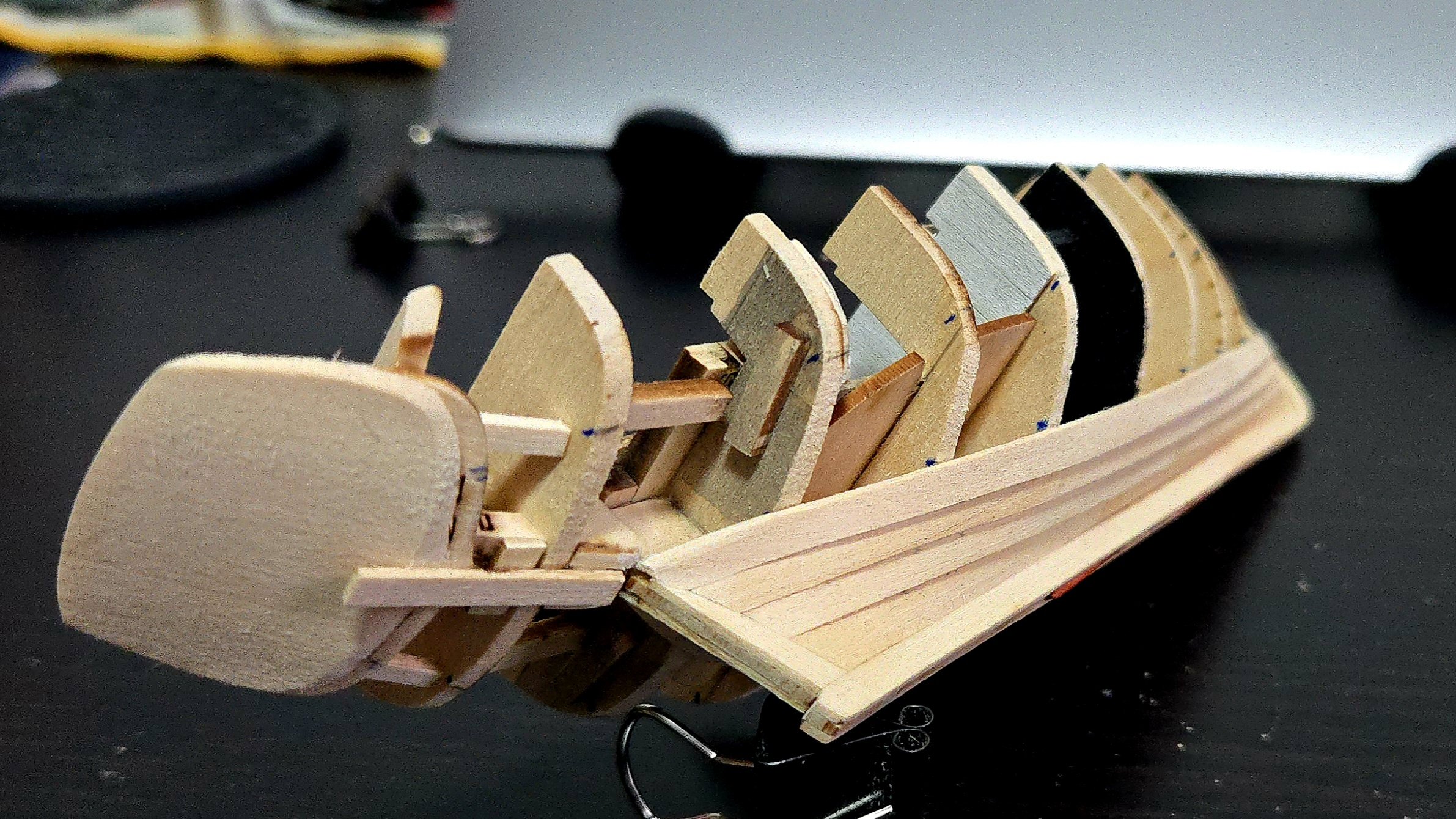
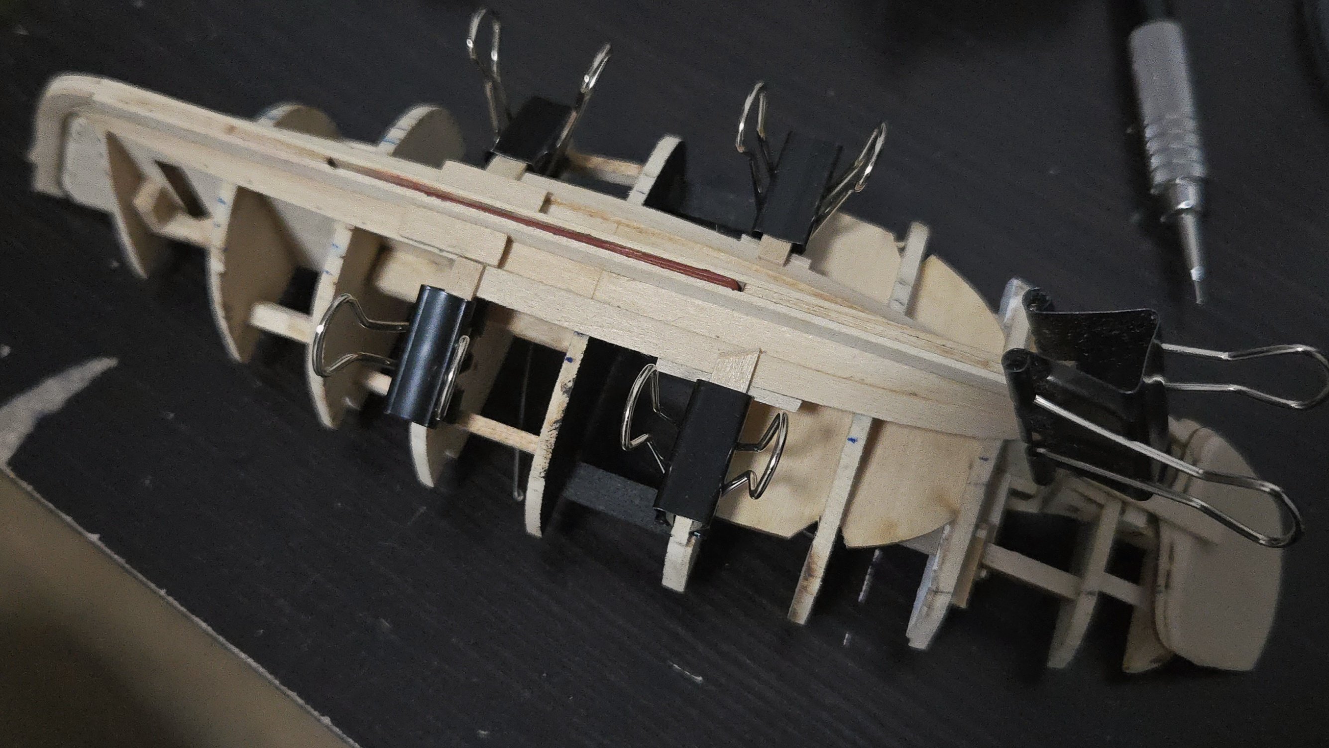
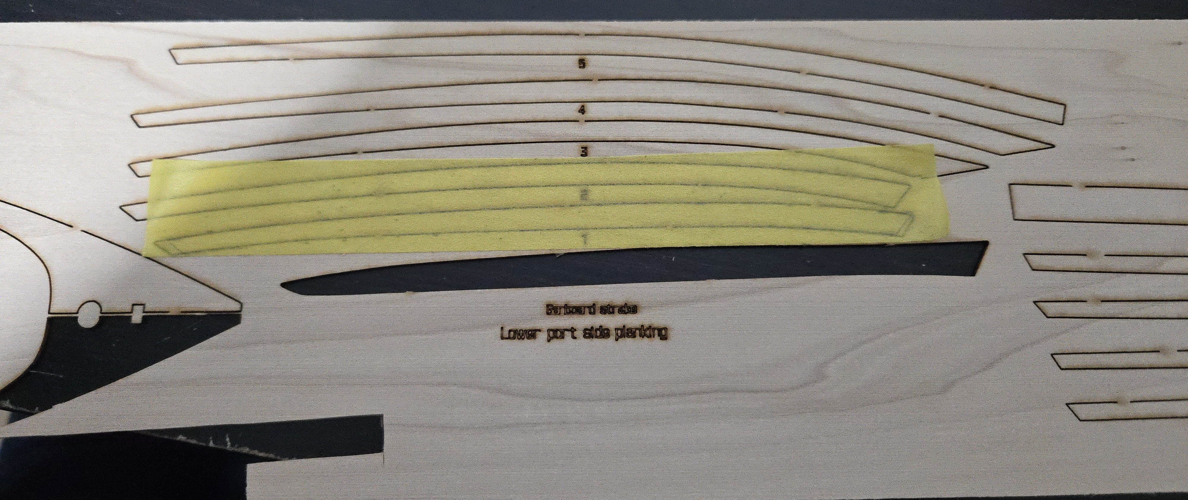
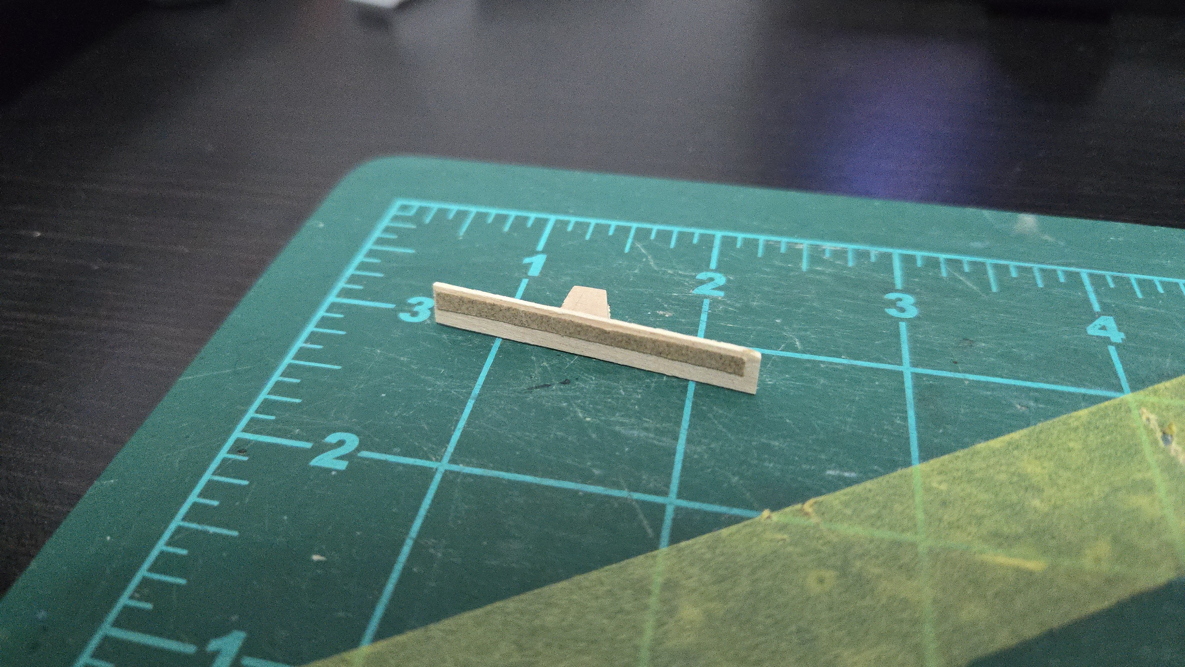
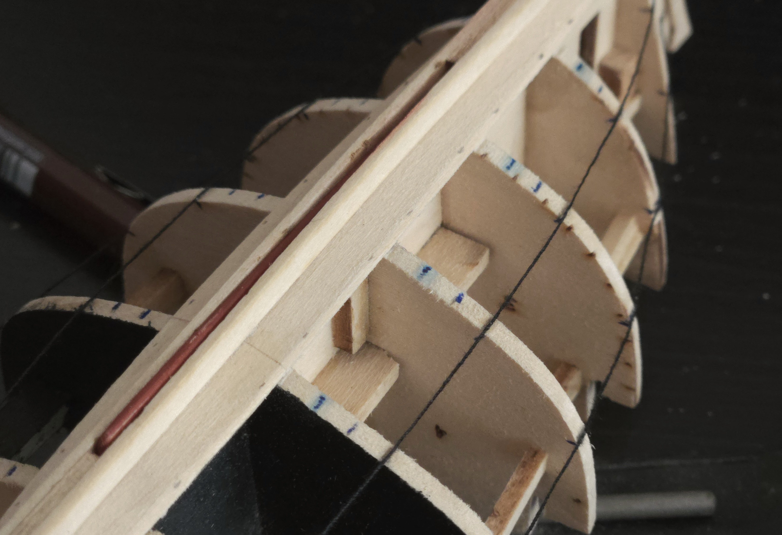
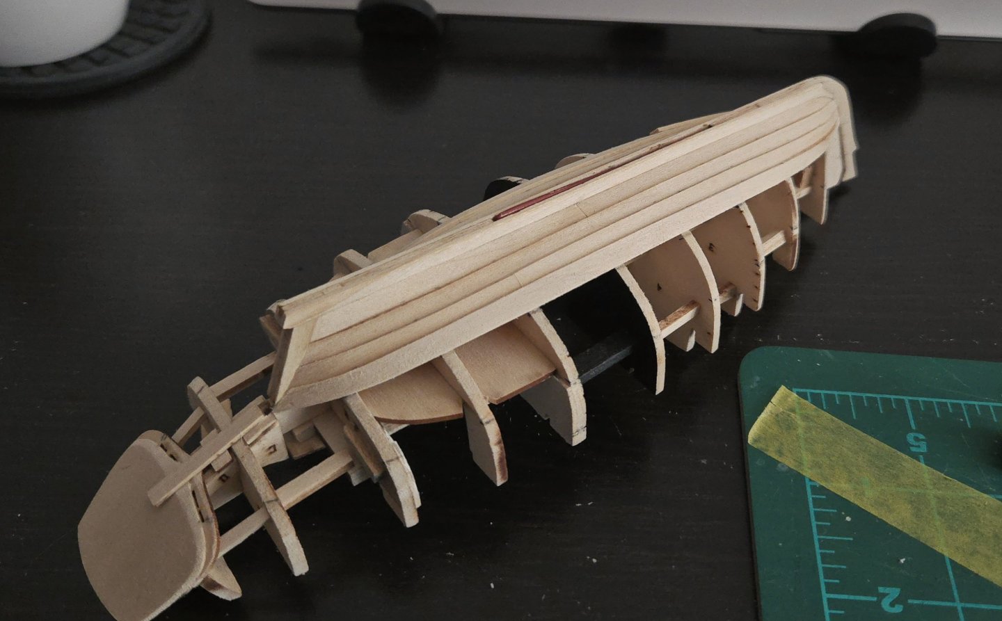
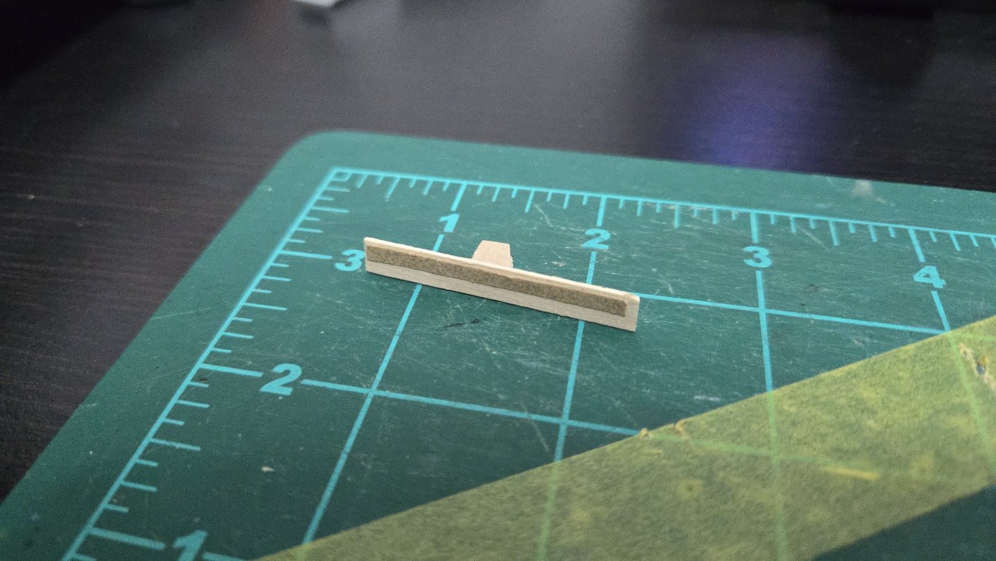
I've started planking! After making some adjustments to the run of the threads, I was happy with my planking bands. Before I could start planking, I needed to prep the lands on the garboard. I'm doing a somewhat simplified lapstrake construction in which the planks are beveled at a 45-degree angle at the bow and the stern, so that the strakes lie flush there. (This part I shape before the plank is attached to the hull). Over most of the strake, though, they overlap, and the lower strake needs to be slightly beveled for the upper strake to overlap it over a flat surface. Following the example from Druxey's Greenwich Hospital Barge build, I made a small sanding block about the width of a plank, with sandpaper over half of the surface. That way I can place the sandpaper-less side against the bulkhead and sand the lands into the lower strake at the correct angle to receive the upper strake. Once I sanded the lands into the garboard strake (which is barely visible in the photo below), I marked the overlap so that I could properly mark and fit the next plank. I then used masking tape to mark off the plank shape. I found that the plank shape nearly matched the kit design for the next plank, which is not surprising. The one issue is that, as can be seen below (kinda--the marks on the tape are very faint), the kit designed plank is a bit too narrow towards the bow. So, I decided that this strake will, like the garboard, also be made of two planks. Looking at photos, it seems that it wasn't uncommon for similarly-sized Friendship Sloops to have multi-plank strakes (usually a bit more irregular than the nicely laid-out butt shift patterns we strive for in modeling), so I don't think it's unreasonable. It also makes fitting the planks substantially easier. So I chopped off the too-narrow fore portion of the kit-designed planks and did the required adjusting, and then soaked and bent them into shape. After both aft planks dried, I went ahead and glued them in place. I realized that clamping lapstrake planks is a little different from carvel. With carvel planks, you're not just clamping against the bulkheads, but sideways against the previous strake. With lapstrake, you can't really do that, because there's nothing to keep your plank from just sliding down. I had a very slight adjustment to make to the curve of the plank, and ended up using a block of scrap wood, as can be seen, that happened to be the right size to fit between the plank and the keel. In further strakes, this won't really be possible. With the aft plank on, the way the plank transitions from overlapping to flush at the sternpost is visible.


-
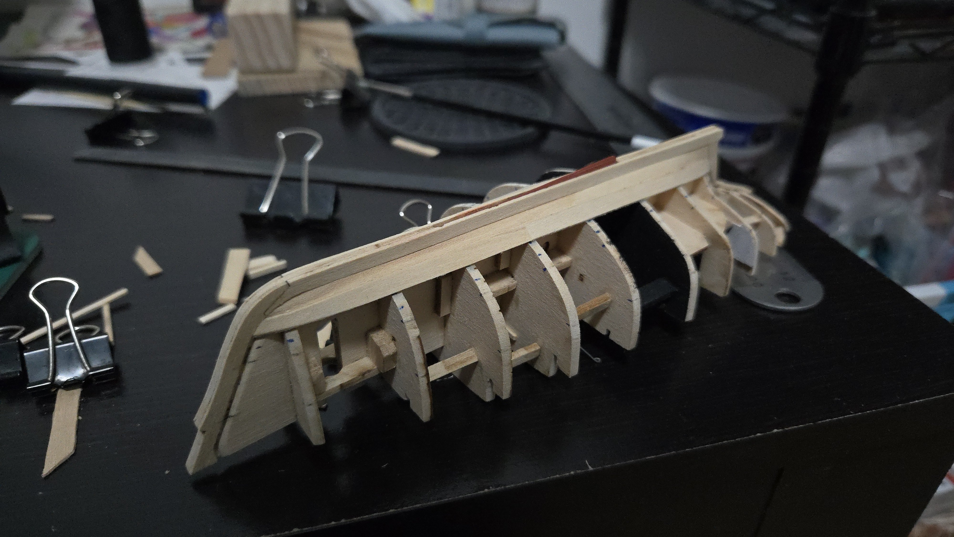
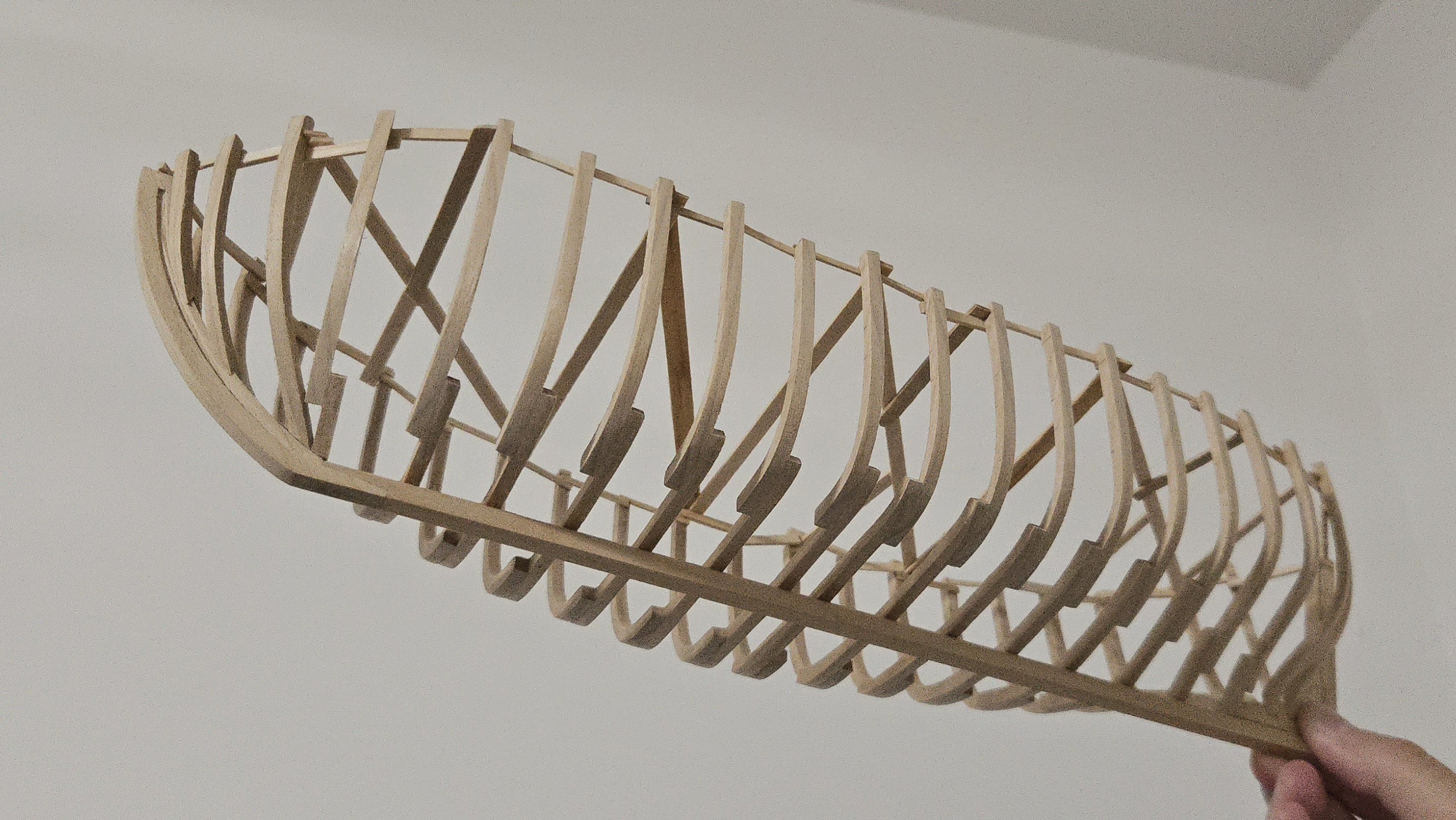
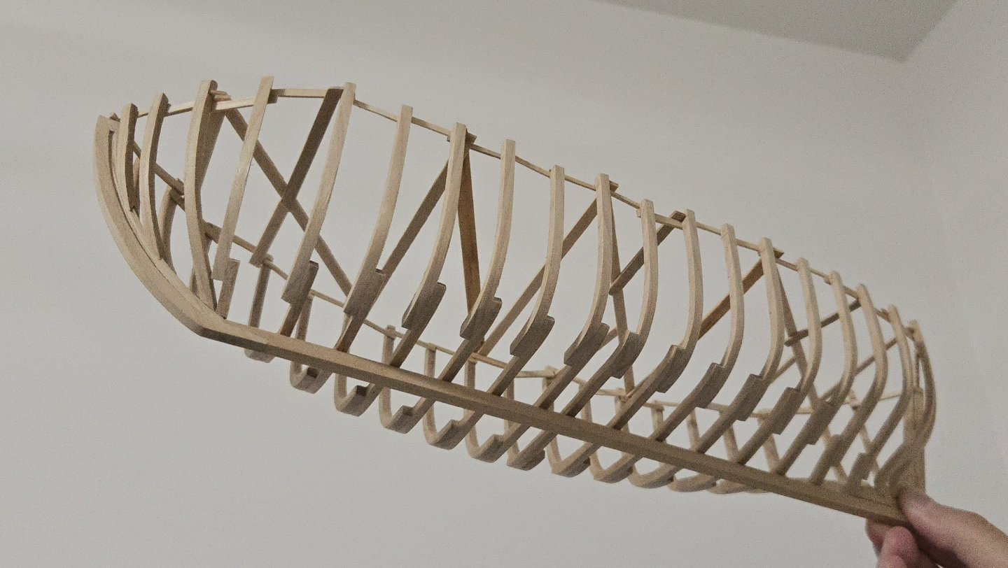
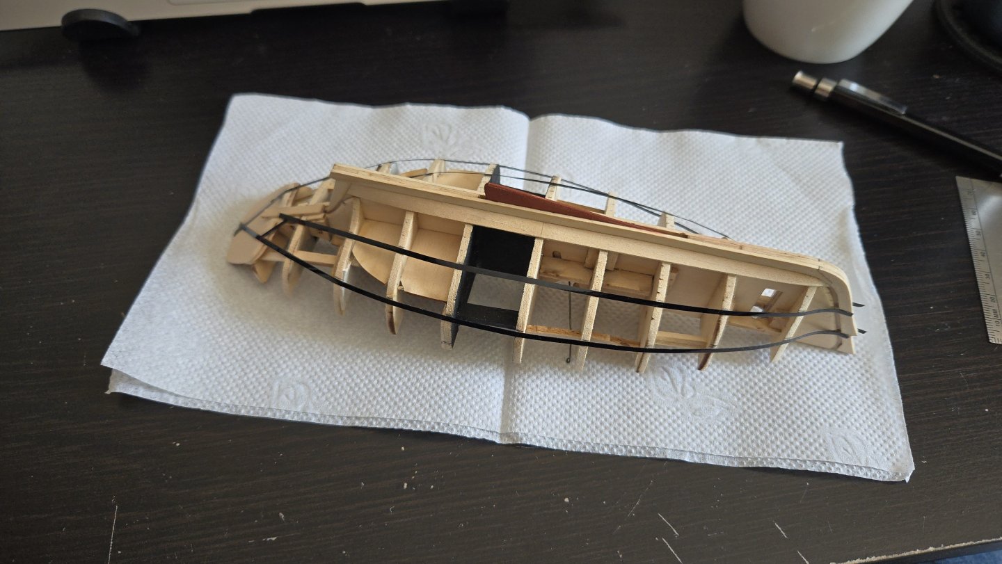
Although I started a new build (the NRG Capstan) since my last post, the Bateau de Lanvéoc hasn't been forgotten. I've been doing a little fairing at a time, as it's pretty tedious and I don't want to take too much off by accident. I'm tempted to say that I cut the frames too wide of the lines, as there's a lot of material to remove to get them down close to the thickness given in monograph, but if I had cut them closer, I would have had less ability to fair things up. So far I've only been working on the port side. Fairing has been going well, overall. The bow needed a good deal of sanding, but I think it's nearly there. I can run a batten pretty smoothly over it. A few frames stood a little proud amidships, but I've gotten those sorted out, for the most part. The stern is tricky due to the extremely rounded shape. While things look fair running to the aftermost frame, I keep breaking battens trying to then check how they run into the sternpost. I may need to just make a pre-bent batten, as I don't see any other way to check the fairness there. Unfortunately fairing does not lend itself to particularly interesting photos of work in progress, it's just a lot of sanding and checking with a batten. One challenge I've faced is that, early on, I faired several areas with a fore-and-aft sanding motion as there was a lot of material to be removed across several frames. I discovered that this actually broke the glue joints between several frames and the keel, although they stayed in place thanks to the pins I added. I've worked watered-down white glue into all of those joints to strengthen them. It would have been a lot stronger to have added the keelson before fairing, but I was concerned that I wouldn't be able to get it fair in a way that held up once the exterior was faired.
- 139 replies
-
- 10
-
-
- ancre
- Bateau de Lanveoc
- (and 2 more)
-
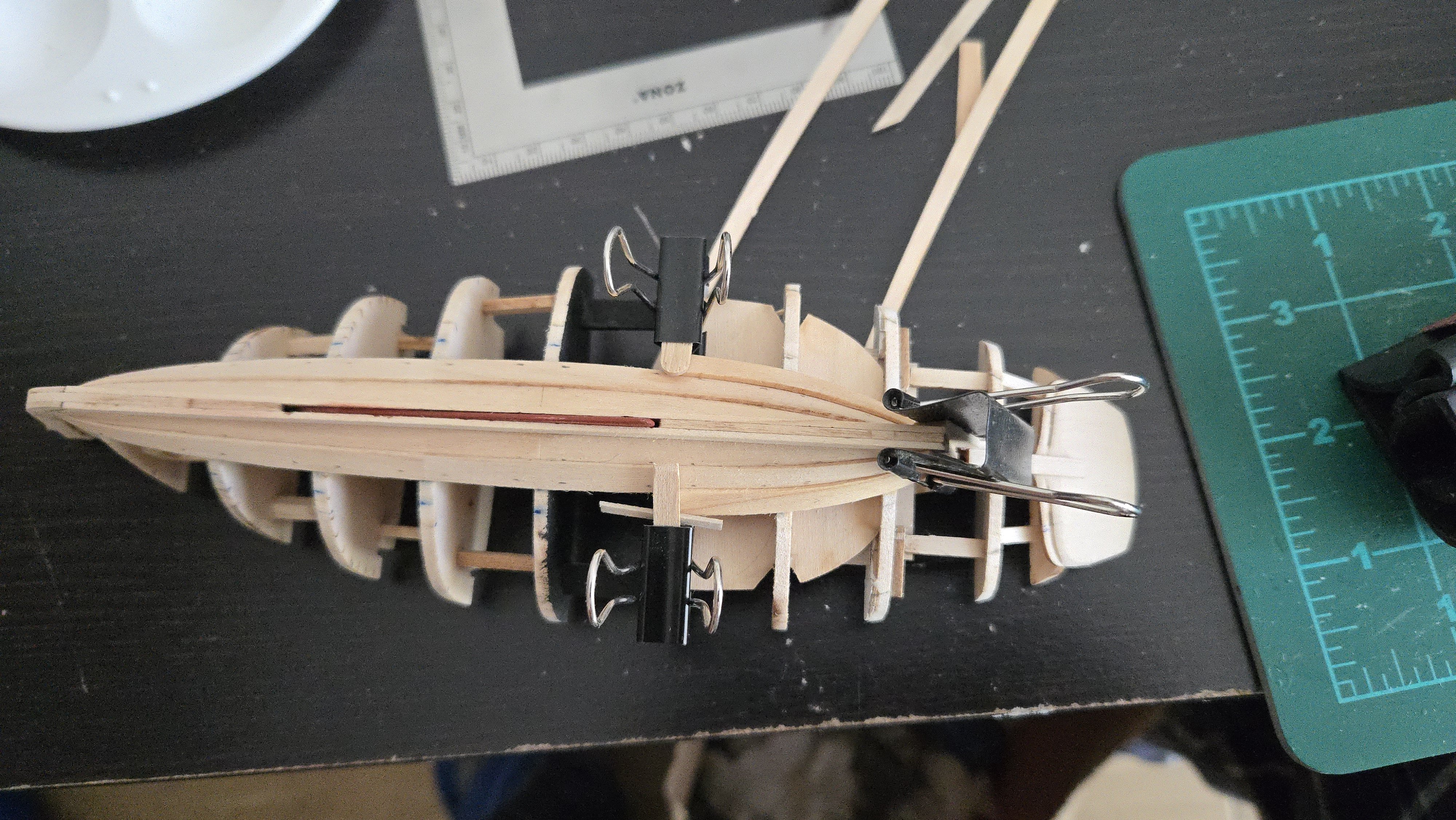
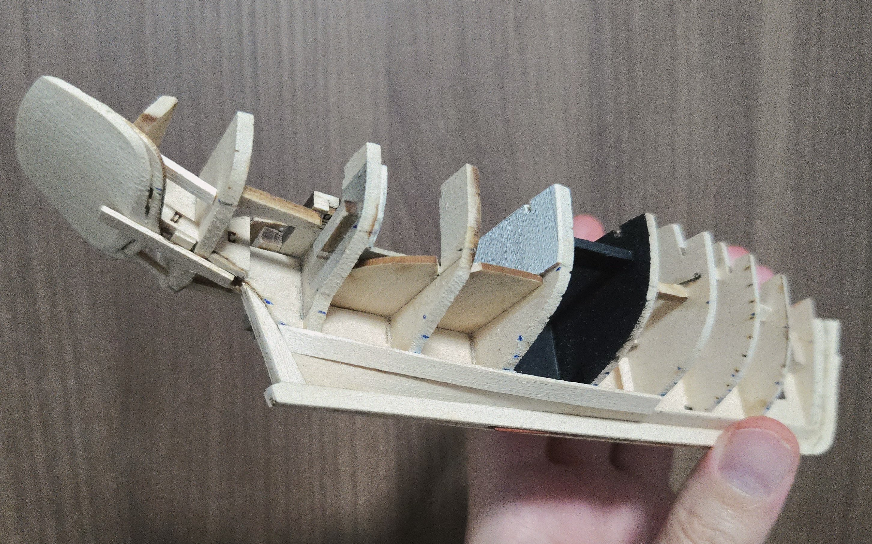
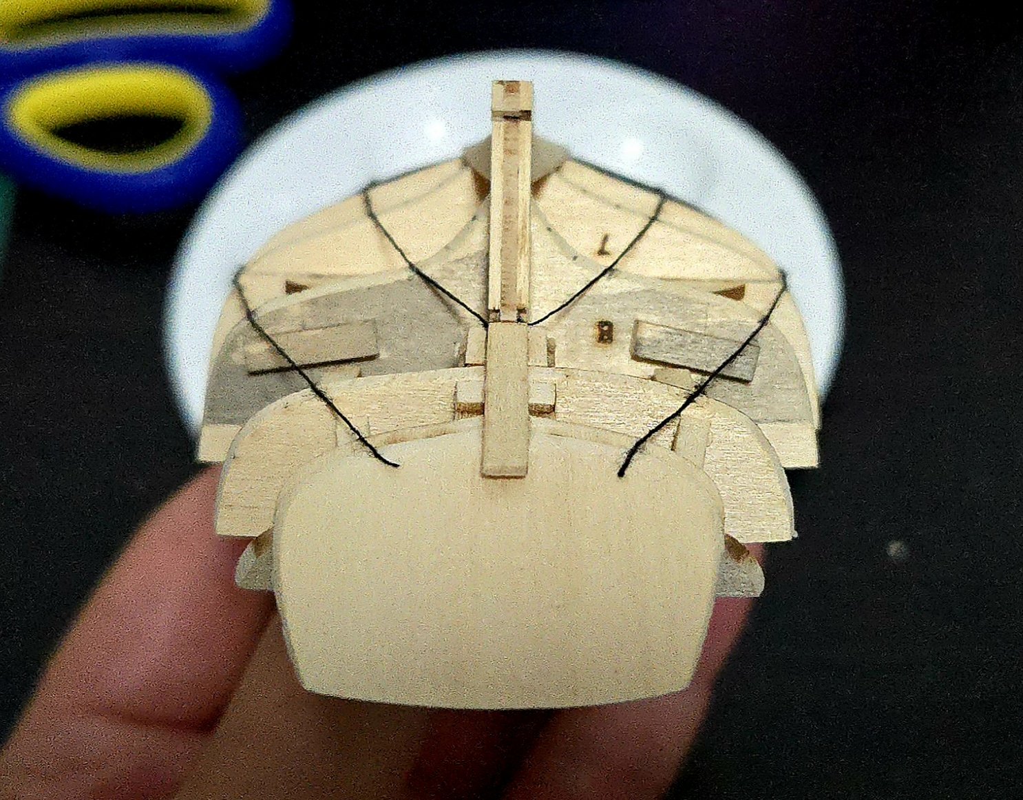
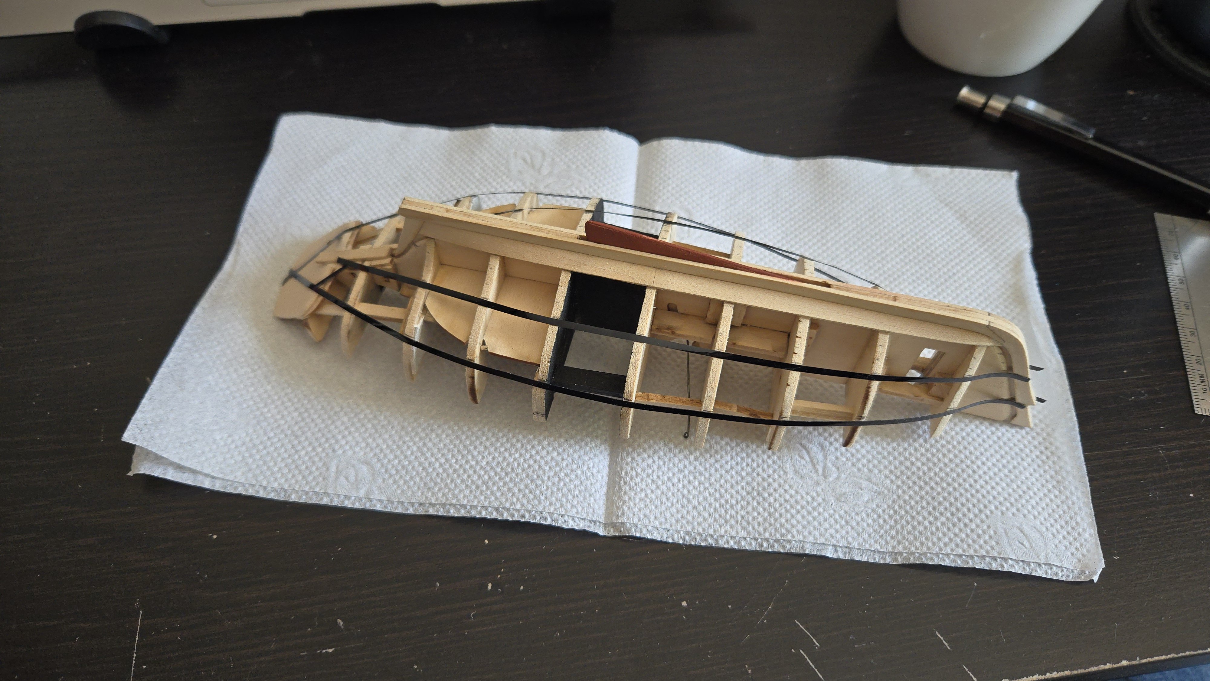
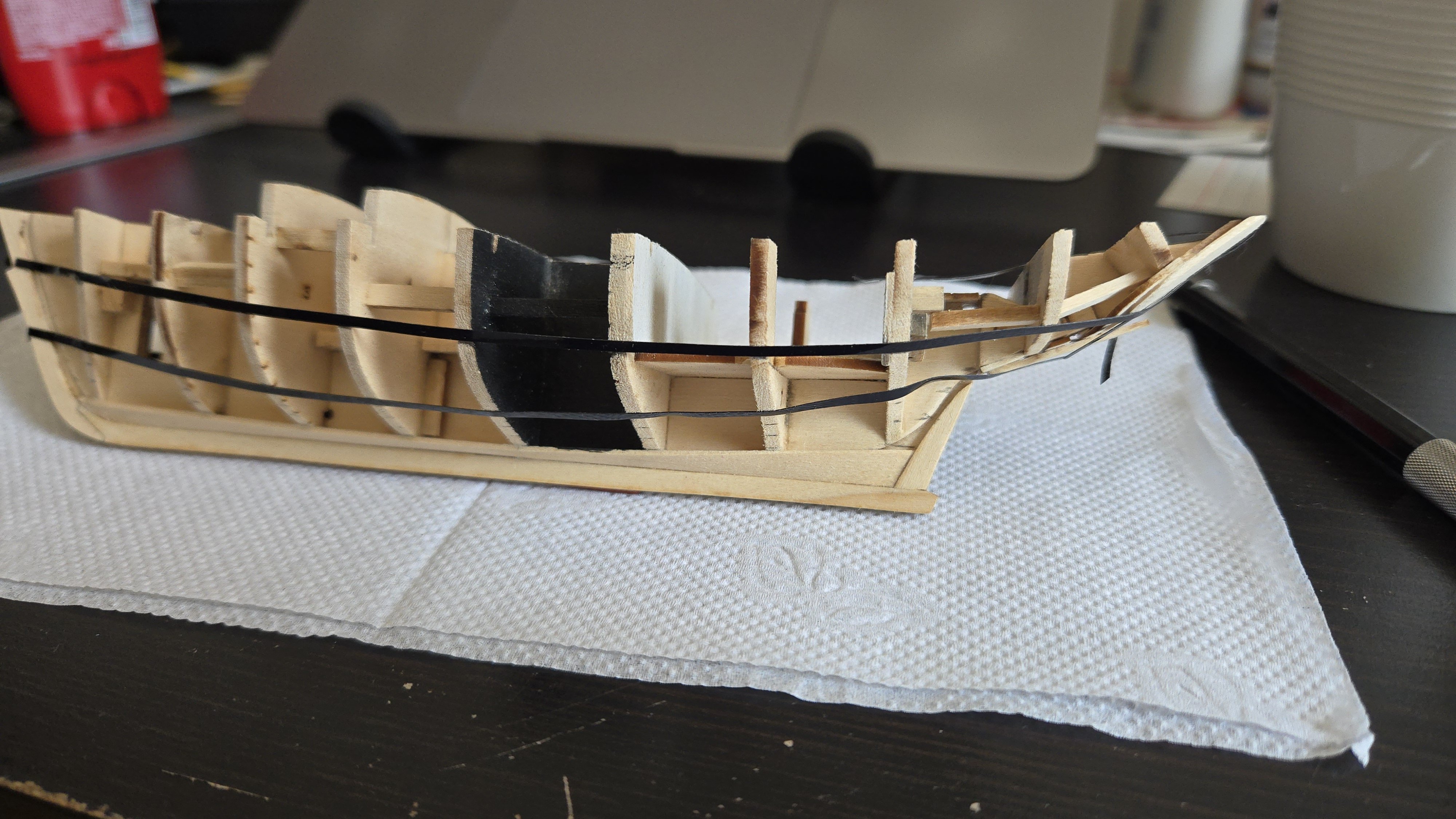
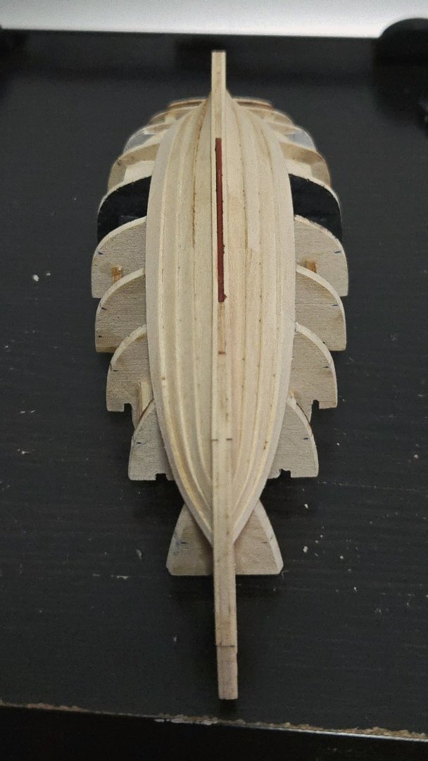
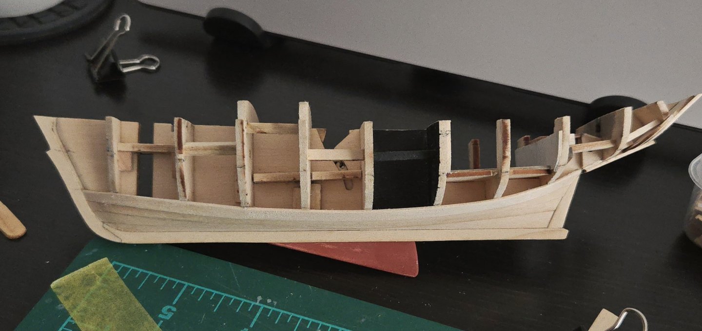
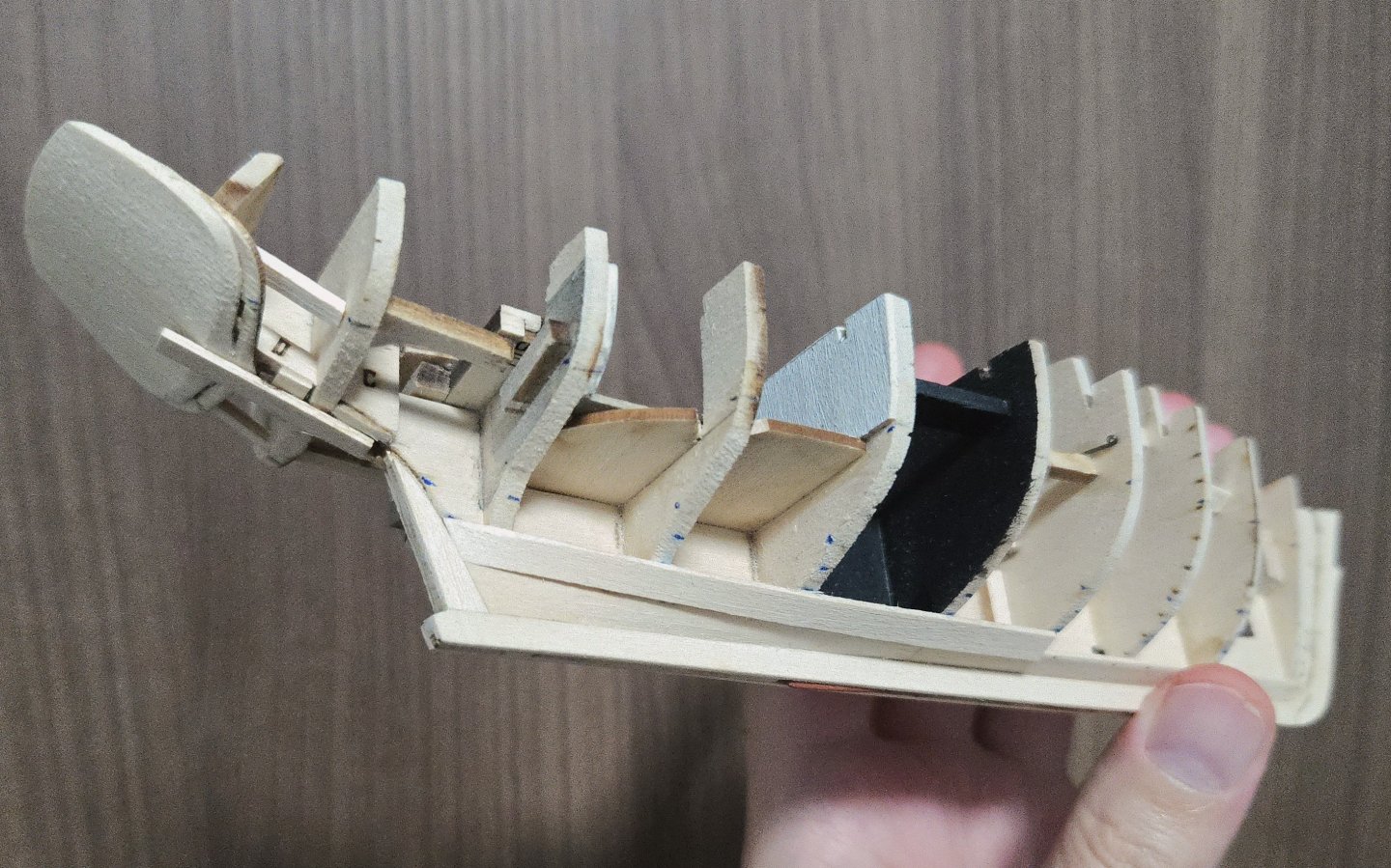
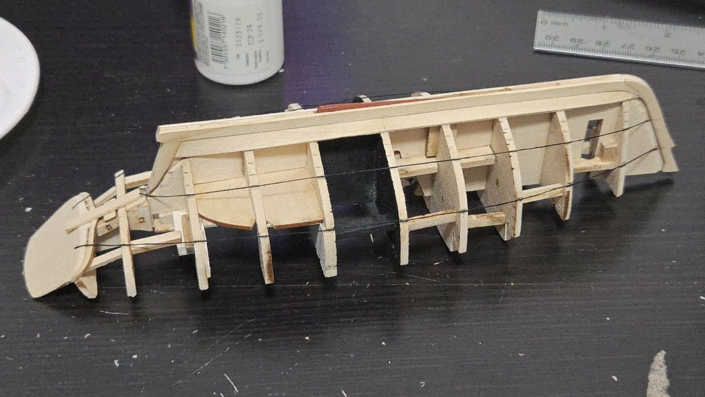
Thanks! I've tried using thread soaked in glue and dampened before, but I never got it to stick. This time, I decided to just secure it at each bulkhead with a small dab of white glue, which I could then dampen to loosen when I needed to adjust the run a bit. The thread is much more precise than the chart tape, which is nice. For instance, in the photo below, the run is very slightly off at the bulkhead just aft of the black-painted portion, being slightly too close to the keel. I hadn't been able to see that before with the chart tape, but thanks to the thread, I was able to adjust. The runs of the planking bands look pretty good now (the slight wonkiness at the sternpost is because I had trouble gluing the thread down there, so one side glued in at a slightly different angle than the other). I'll let it sit overnight to look over with a fresh eye tomorrow, and then it will be time to mark everything out and begin planking.
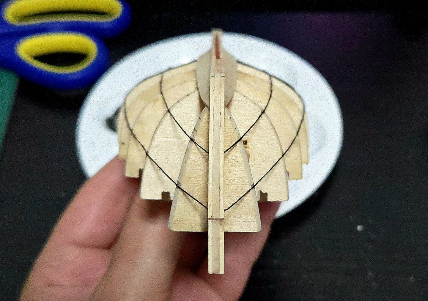

-
I've been working on trying to line out the hull planking. It looks like a lower band of 3 strakes, and two upper bands of 4 strakes each, should work well and will end the lower band right at the top of the sternpost. That said, I've been having some trouble lining off the hull. Close to the stern, the chart tape has to be basically "edge bent," which it doesn't at all want to do, leading to a lot of buckling that makes it tricky to see whether the lines are fair and even to bring the tape in line with the sternpost.
-
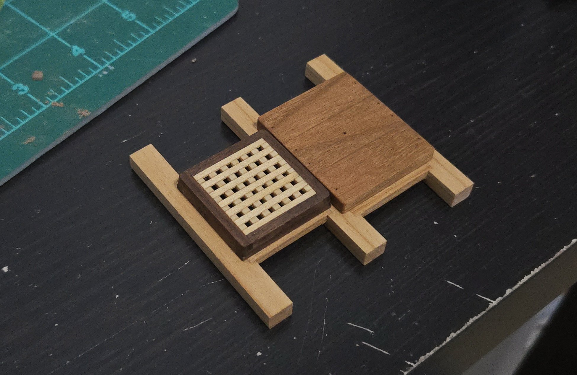
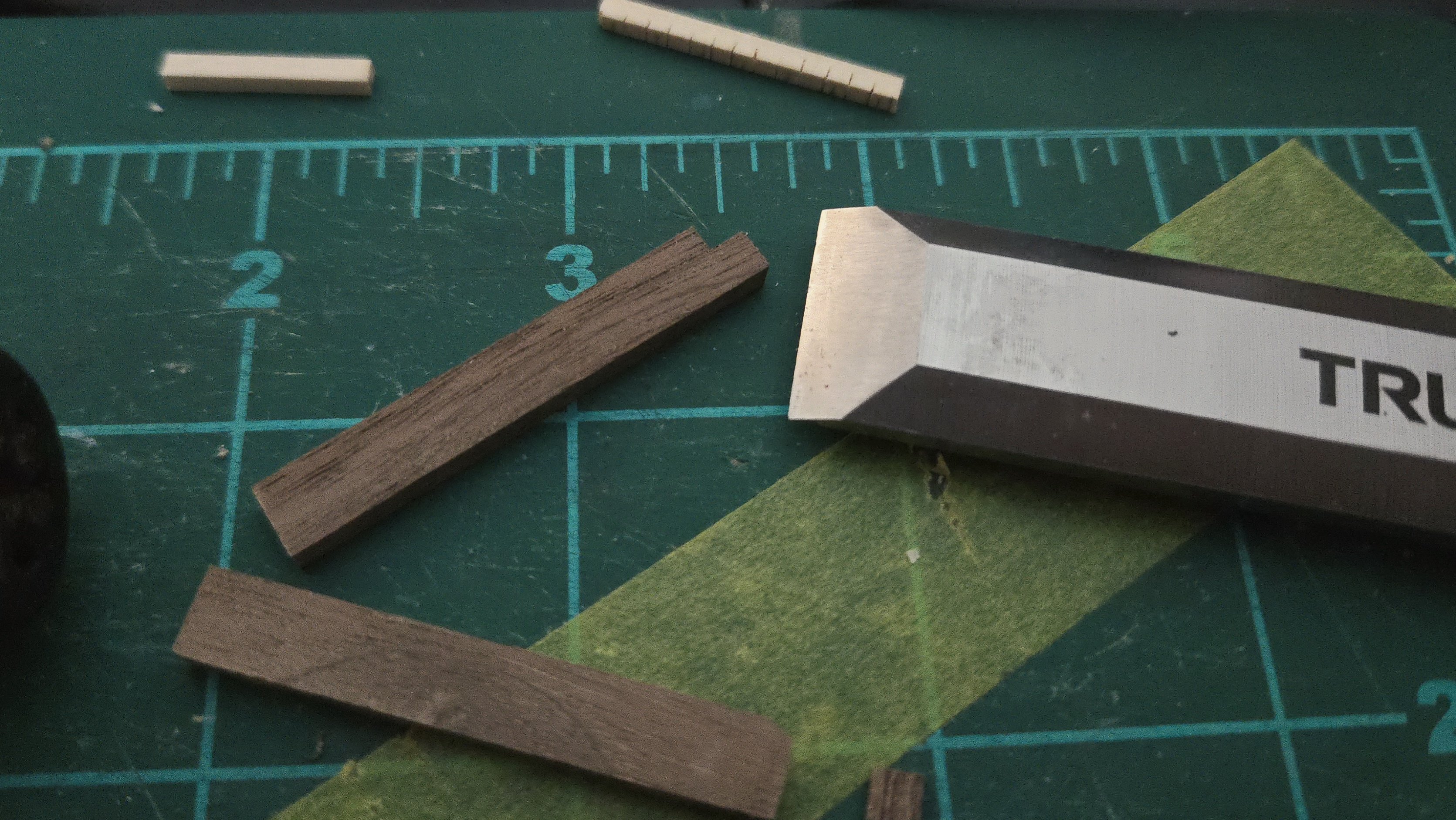
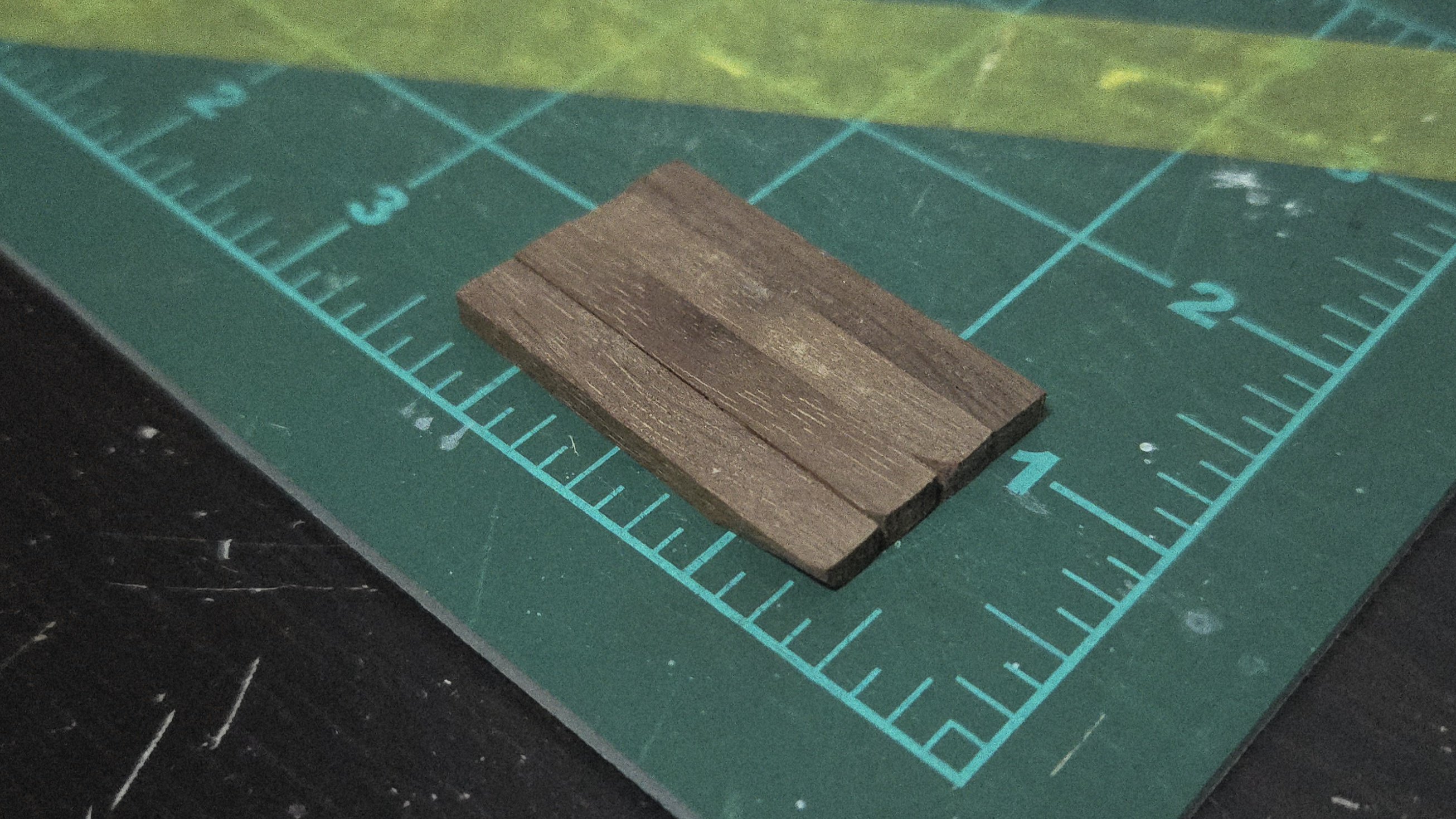
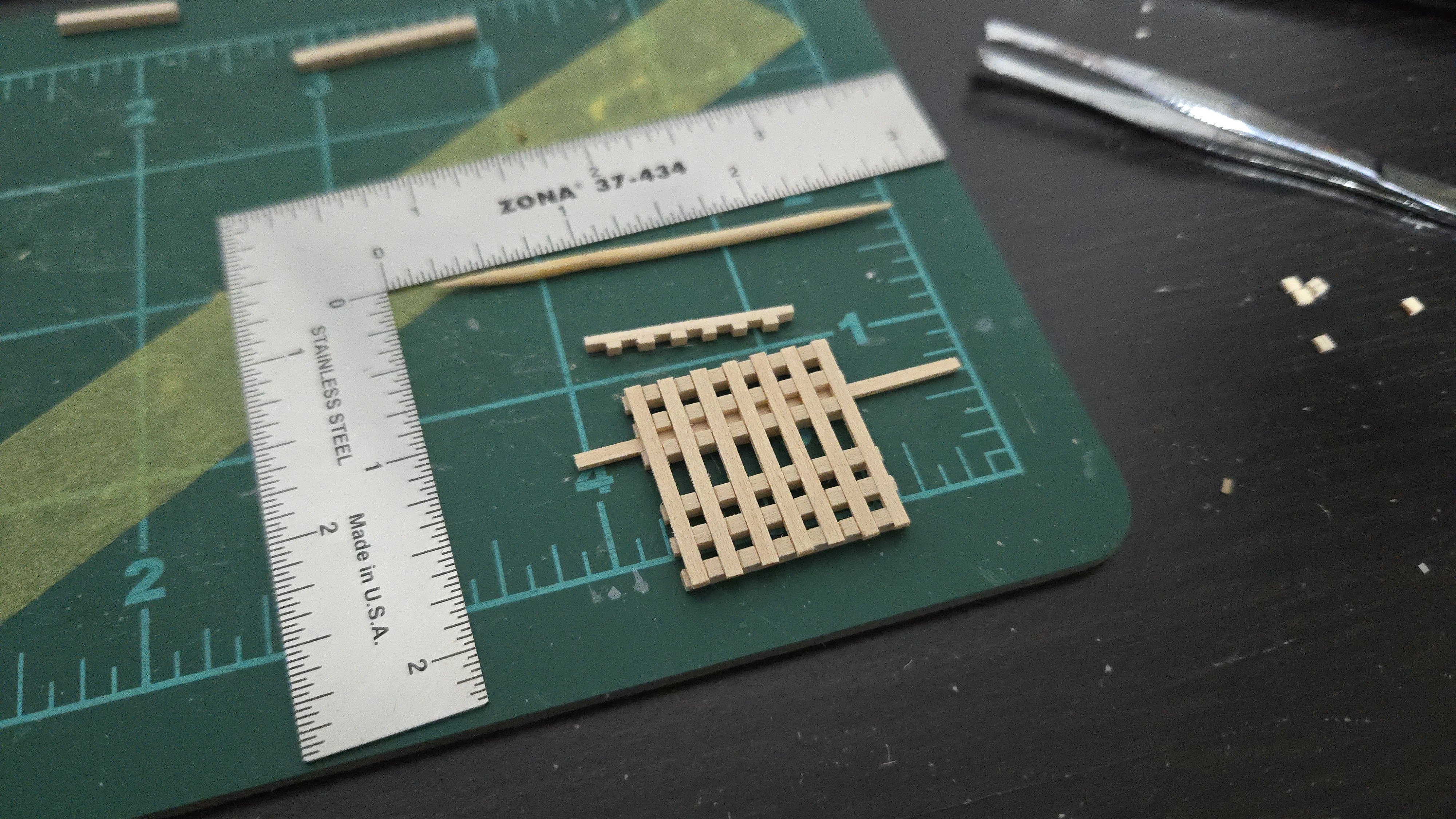
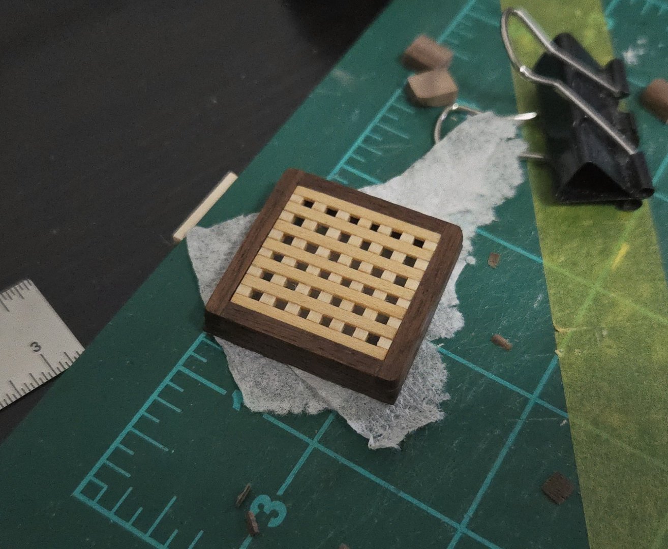
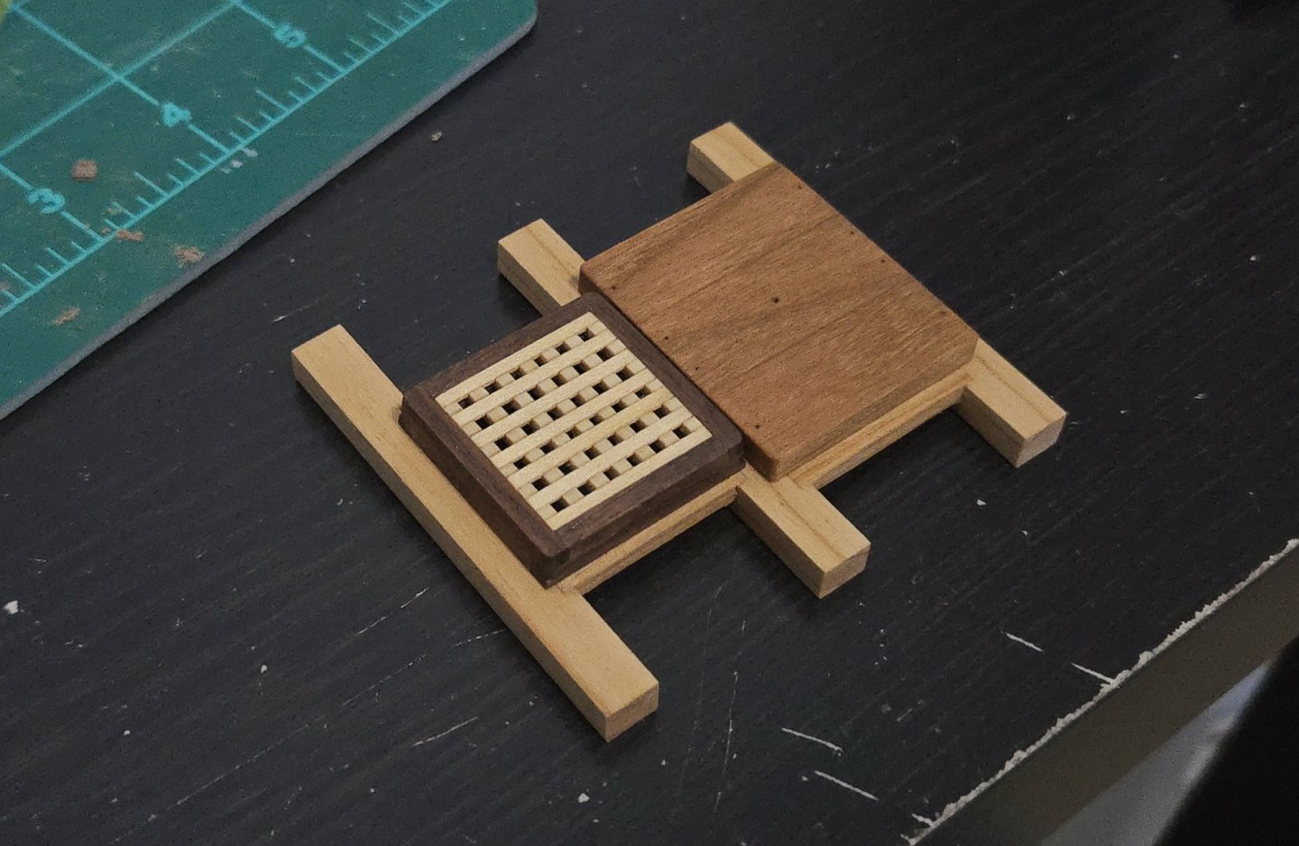
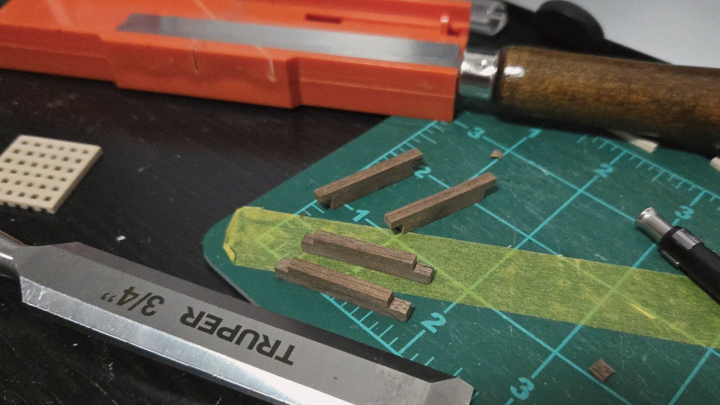
The hatch coaming was much simpler to make than the grating. I started off with some scrap walnut left over from a jewelry box I made, which I cut into somwhat oversized portions with a razor saw and then planed to the correct thickness. Below, I've tack glued the pieces together for the final planing and sanding. I then cut the joints for the coaming pieces. I went with the simplified basic lap joint given in the intermediate instructions, rather than the more accurate but more complex joint shown in the advanced. I used a razor saw and a chisel for this. Using a 3/4-inch chisel on such small parts took some getting used to. The chisel cut the wood quite nicely--having only used it on pine before, I can really see why hardwood is often said to be easier to work with for this sort of precise work. The joints didn't turn out quite perfect, and one had to be built up slightly with a shaving of walnut when I cut the joint slightly wide. The rabbet was added separately, using a bit of 1/16-inch walnut strip from a kit. I have to say, while I've read a lot of comments about walnut being too hard to work with and unsuitable for modeling, I found it to be very nice to work with. Maybe I got lucky, but I've found that it cuts, planes, and sands beautifully. (Granted, I'm not trying to bend it or anything.) The grain may be a bit large for scale, but at least on this model I'm not really concerned about that. I then began gluing everything square. Once the coaming was glued together, the grating required very little sanding to fit. I then sanded the edges, including the taper and the rounded corners. And then added some linseed oil. This really brought out the color of the walnut. Here's the hatch assembly resting in place. Although I suppose I could have made the grating a bit more consistent, I'm pretty happy with how it's turned out.


- 32 replies
-
- 18
-
-
- NRG Capstan
- NRG
- (and 1 more)
-
I can't really tell what the mistake is from the photos. Is it that there's a bit of a gap down the middle? If so, maybe you could add a king plank down the center. If there's a gap on the sides of the deck, maybe some waterways could fix the issue?
-
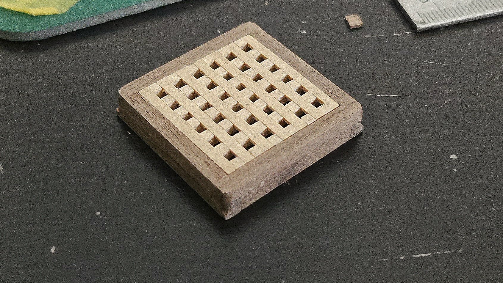
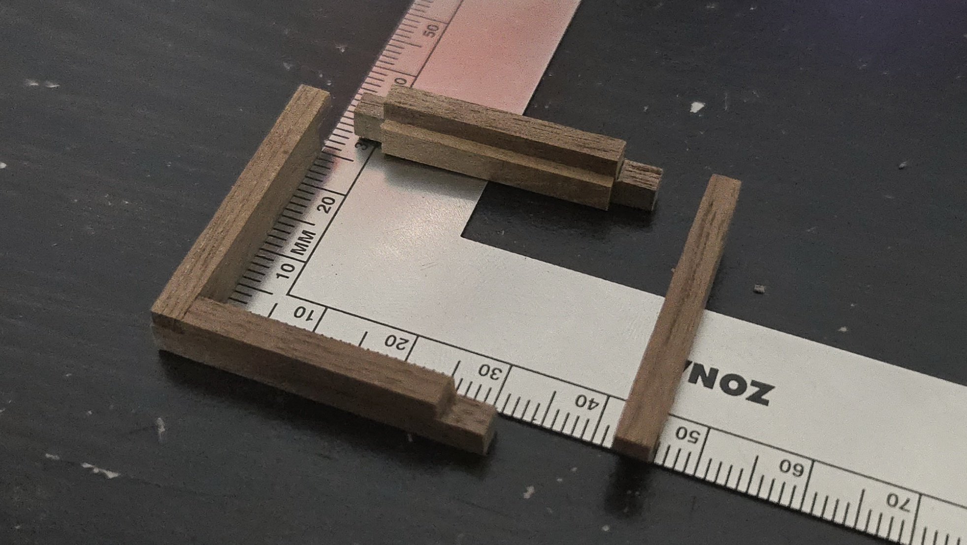
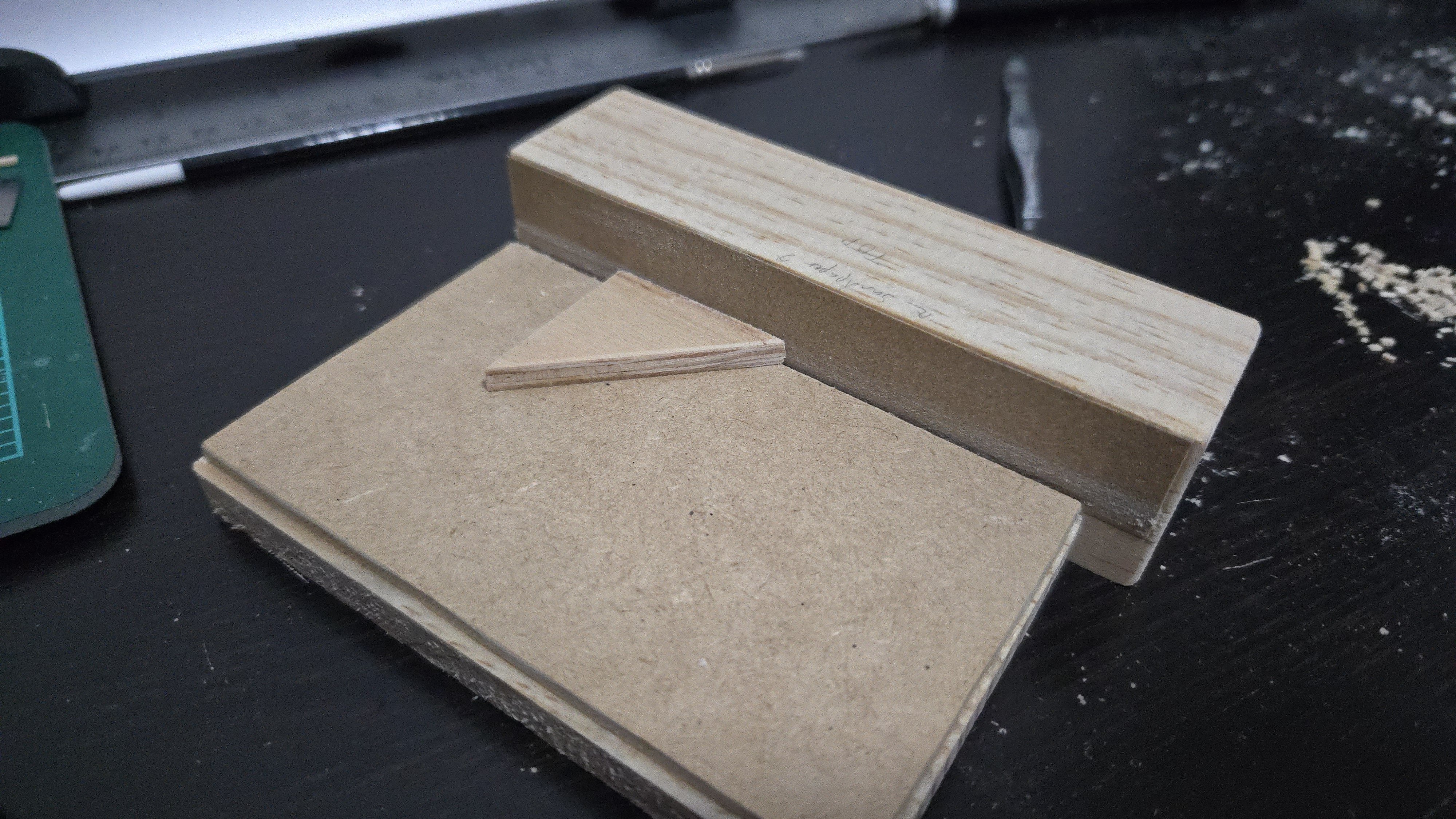
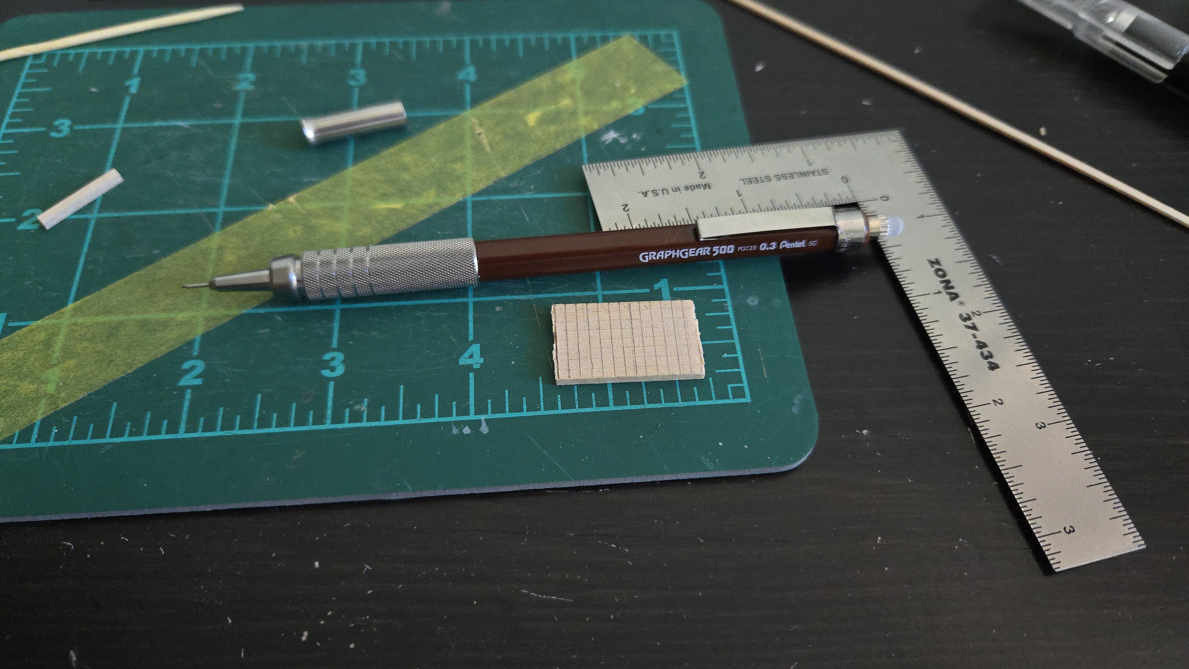
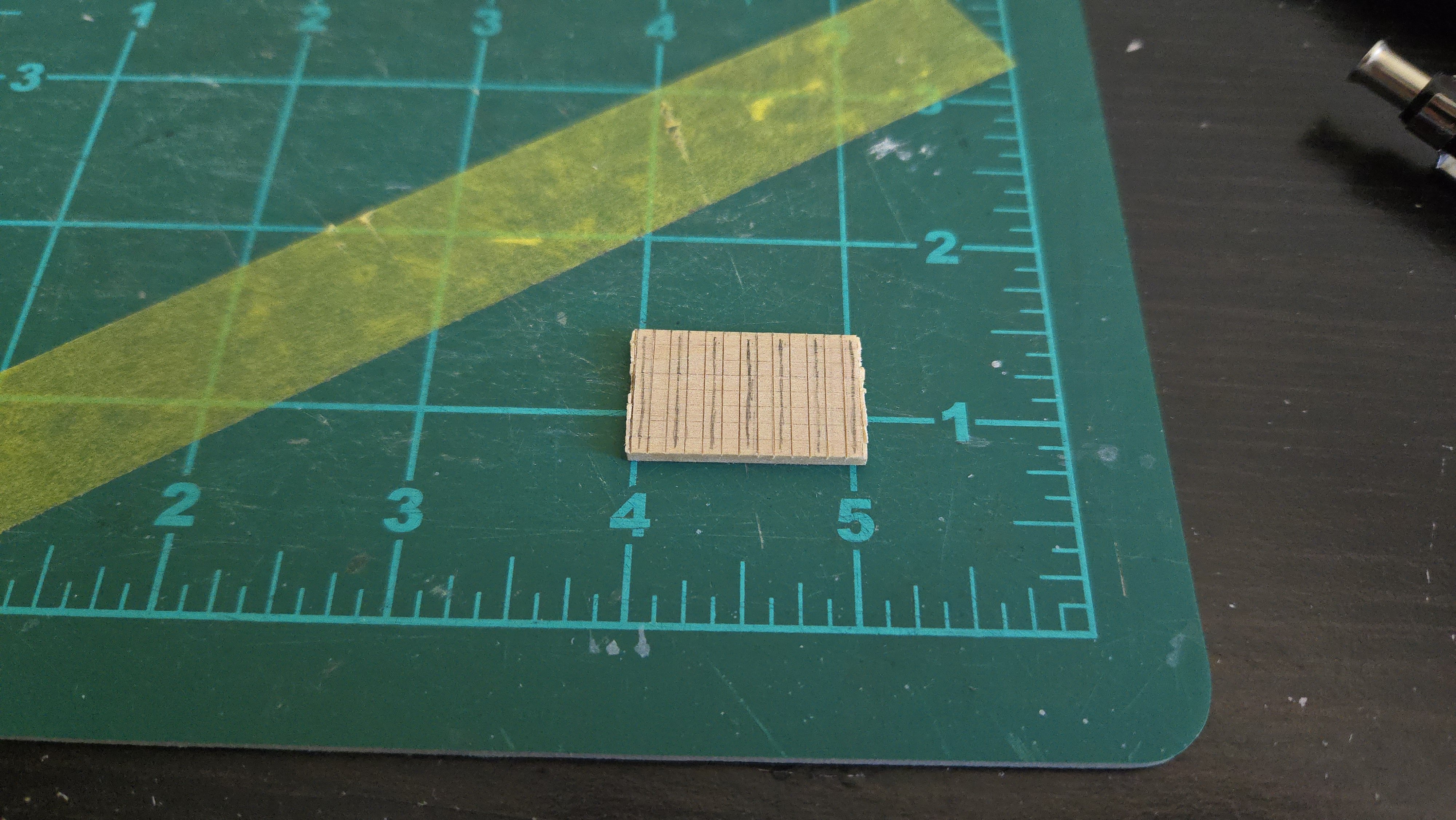
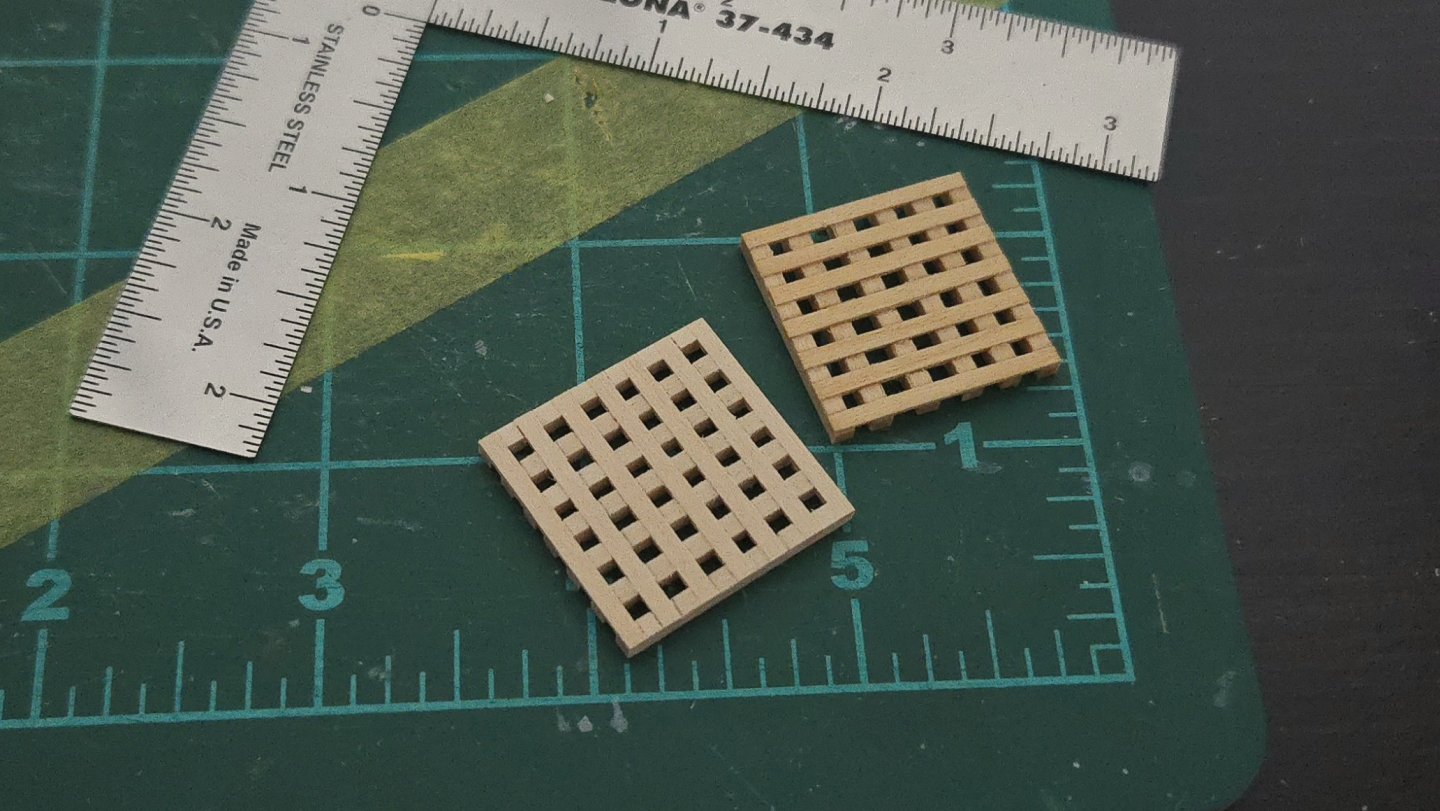
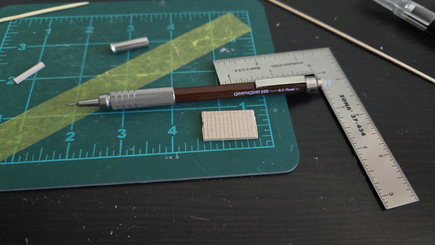
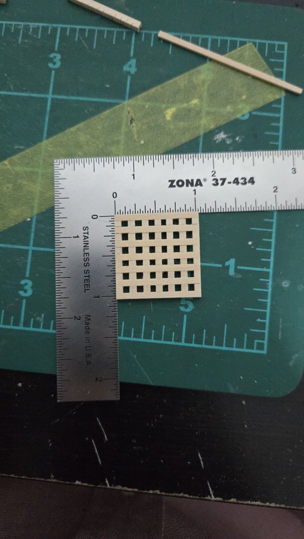
Thanks, Paul! I'm happy to say that version 2 turned out much better. This time I was better about using my digital calibers when preparing the strips of basswood in the right thickness. While I couldn't get them exactly the same width across the whole length, they were much closer than in attempt 1. I then trimmed to length and sandwiched the ledge pieces to cut the notches. This time, I used a very thin (0.3mm) pencil to mark out the cut lines. It took several tries before I got them set up in a way that worked for the required dimensions--being consistently off by 0.1mm is enough to significantly screw up the grating. I then marked the lines with a knife and marked which were to be cut out as notches. Then, I used the razor saw, followed by an X-acto knife, to cut the notches out. I made the notches deeper than attempt 1. When it came time to glue everything up, I used a spare bit of batten material to get the ledges properly spaced. As can be seen, this time I was able to get the right number of ledges on the grating! Despite exercising much greater care, the central ledge still ended up having slightly narrower spacing than the others, but I felt that ungluing to redo it had a high chance of damaging the notches (the basswood is rather fragile and they wantec to split off). I think I can live with it. To square it up, I used a simple sanding block/platform that I made from scrap pine and mdf. Although in hindsight I should have located the 45-90-degree angle jig piece elsewhere on the platform. The block with sandpaper on it is free and you just place it against the edge of the platform's lower piece to sand straight. Despite the grating's faults, it looks a lot better than attempt 1. And it measures 1-1/32-inch square, as it should. (Or at least close enough).


- 32 replies
-
- 15
-
-
- NRG Capstan
- NRG
- (and 1 more)
-
Welcome!
-
Nice work! If a frame's out of alignment, it would be much easier to correct it now before it throws off the run of the planking. If you've been using pva glue, you can loosen it with rubbing alcohol. It's hard to tell from the photo how misaligned it is, though.
- 45 replies
-
- 3
-
-
- Dory
- Lowell Grand Banks Dory
- (and 3 more)