schooner
-
Posts
741 -
Joined
-
Last visited
Content Type
Profiles
Forums
Gallery
Events
Everything posted by schooner
-
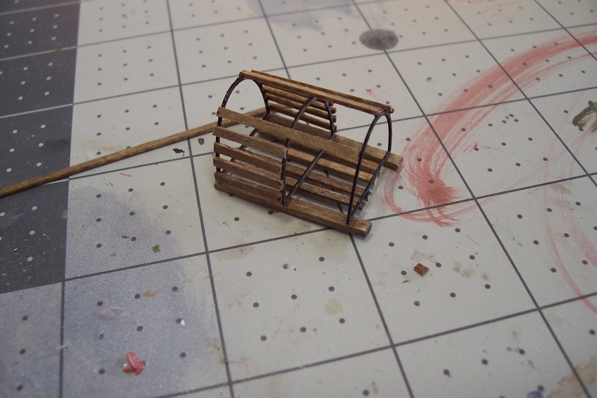
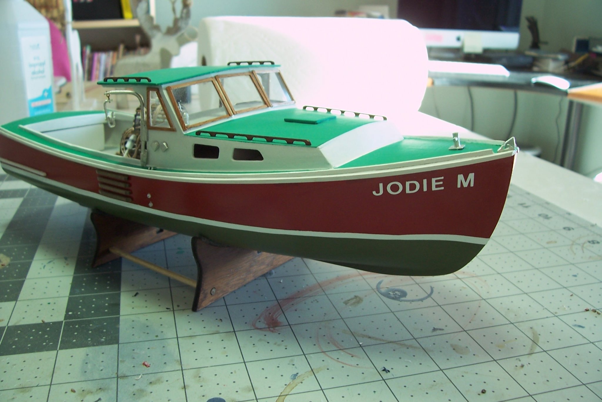
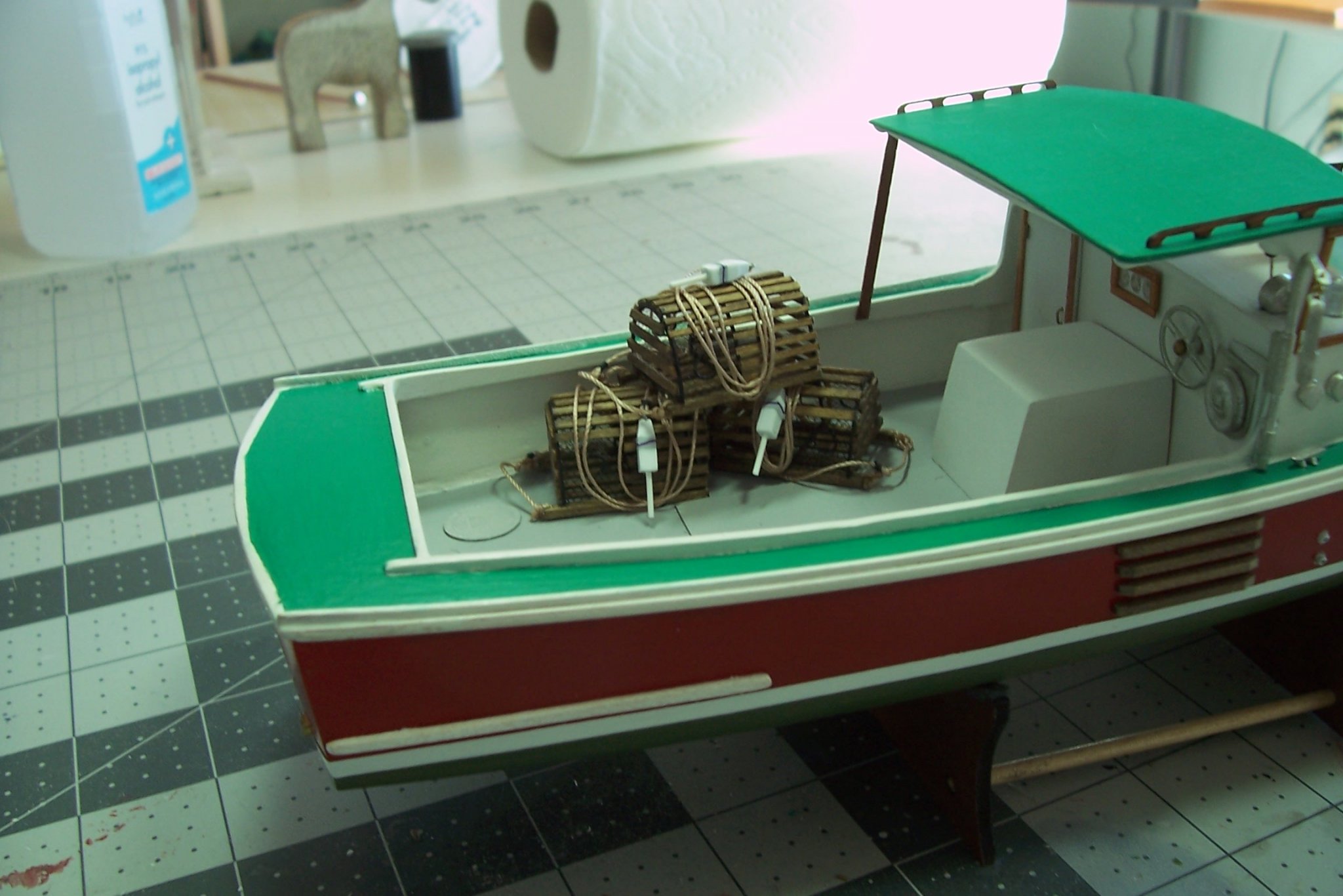
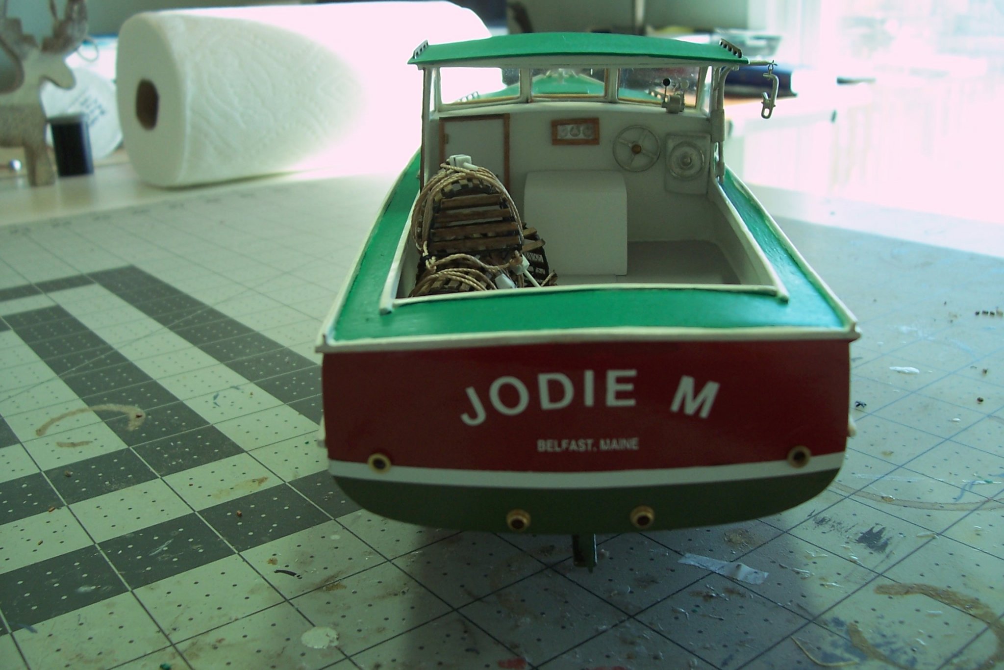
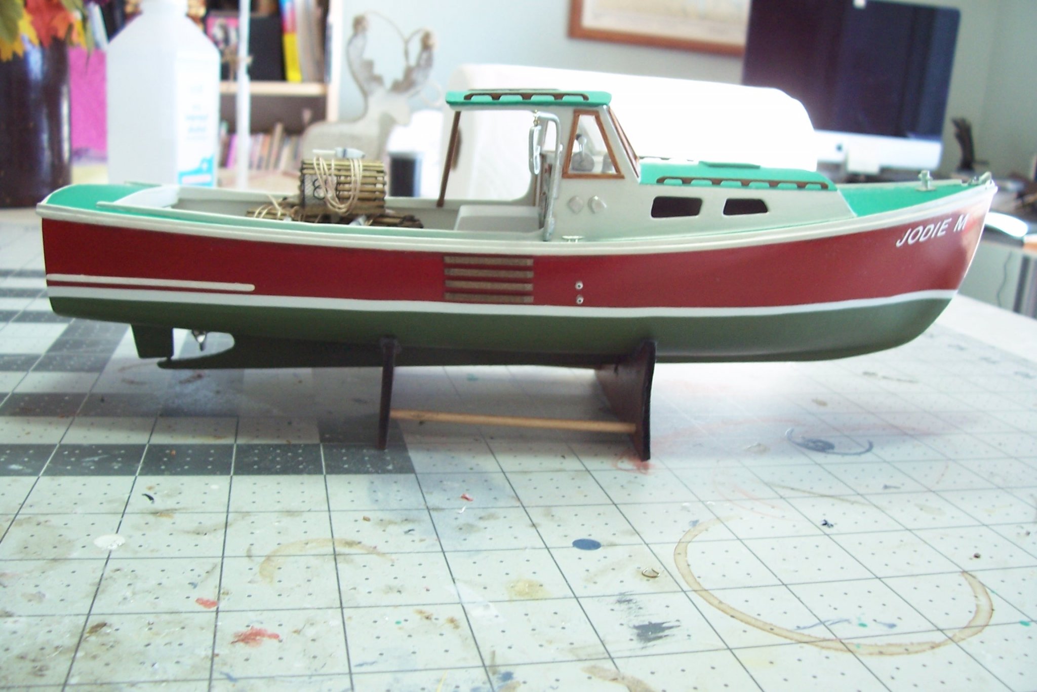
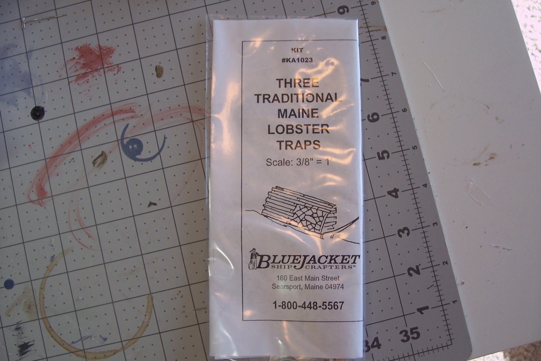
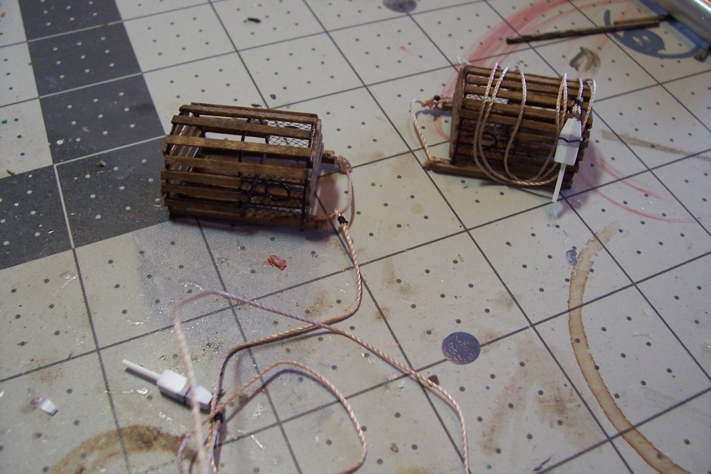
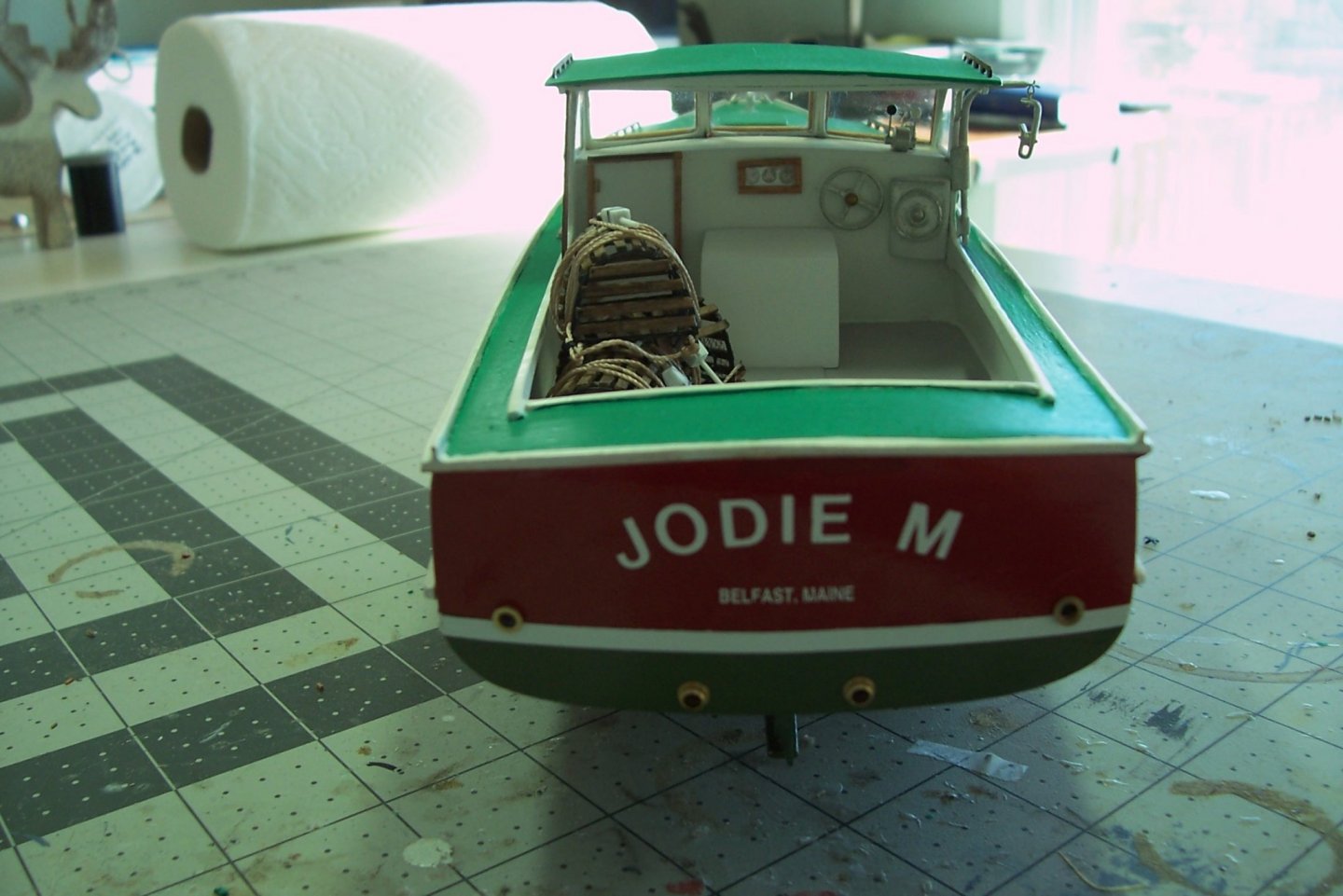
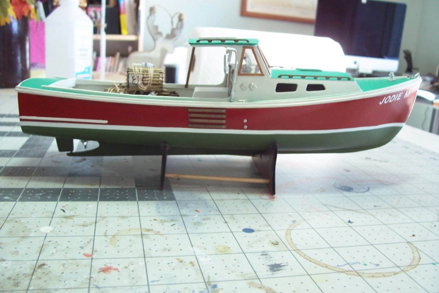
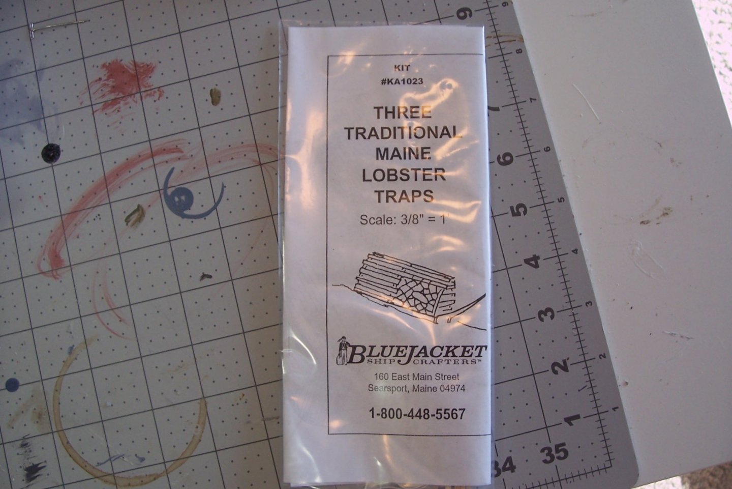
 Lobster Pots and Done! The kit provides a mini-kit for 3 lobster pots, with strip wood, nylon mesh and line included. I stained the strip wood before assembly the glue wouldn’t prevent the stain from penetrating. I had some black florist’s mesh on hand so I used that in lieu of the kit’s white mesh and I substituted some larger line I had on hand. The pots went together without a problem - the floats are scratched from plastic. The name letters are stick-on vinyl lettering for my granddaughter’s name. The home port lettering are dry transfers from the kit So with the addition of the pots this build is done. The “Pros” for this kit as I see them are: As advertised, this is a good kit for a first time solid hull build, there is enough shaping to learn how to do it but it is not too complicated Size - This kit will easily fit on a bookshelf Details - just enough and the ones provided are not too delicate to stand up to dusting so this model really does not need to be cased. This build is 99.9% out of the box, the only scratch details I added were the lobster pot floats and the protective stripping on the hull under the pot davit (a lot of boats have them and I thought it would make it look a little more “lobster-boaty”) No “Cons” as far as I am concerned. Altogether an easy and enjoyable build.


- 20 replies
-
- 7
-

-
- red baron
- lobster boat
- (and 2 more)
-
Thanks Chuck! A compliment from Dear Leader is greatly appreciated.
-
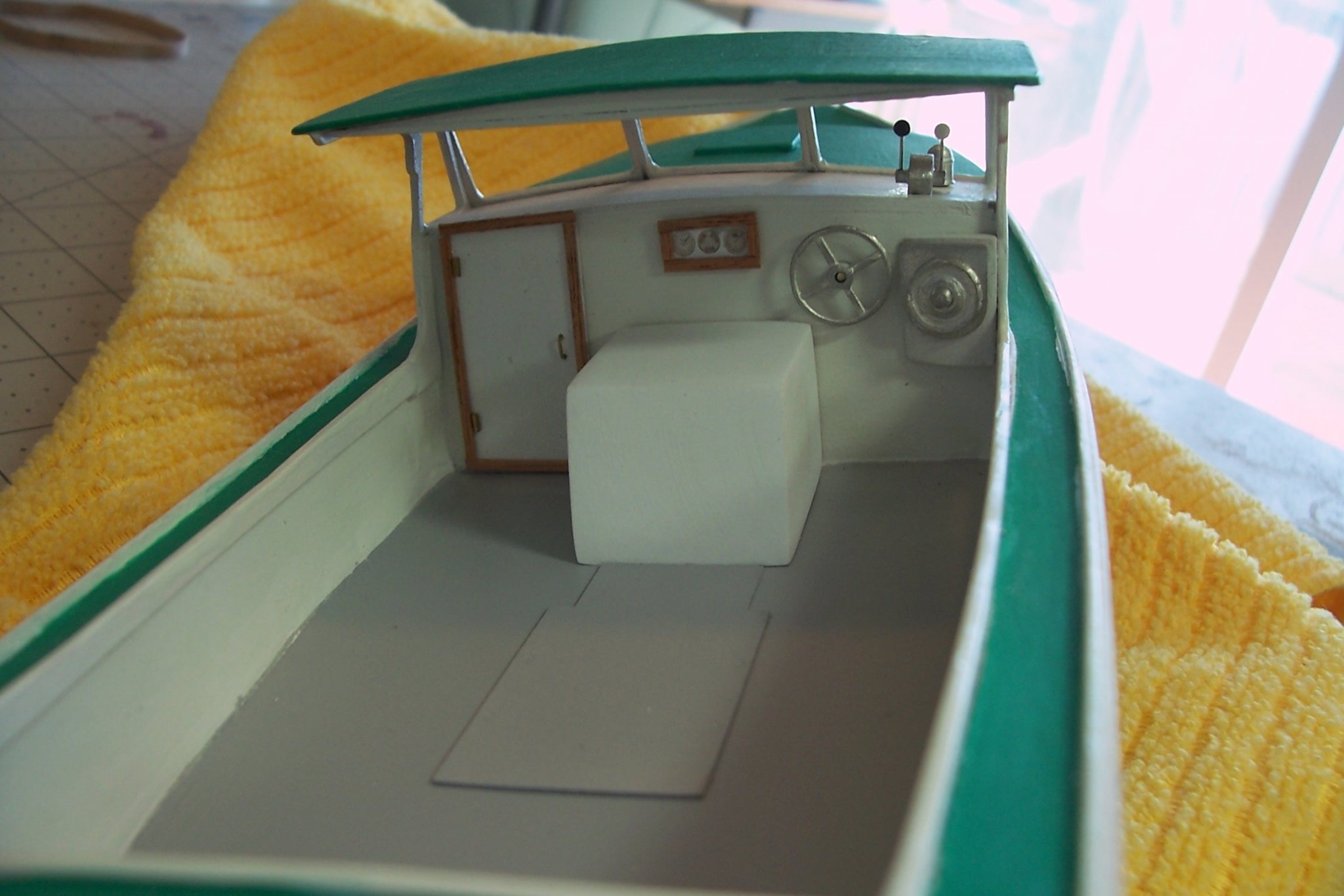
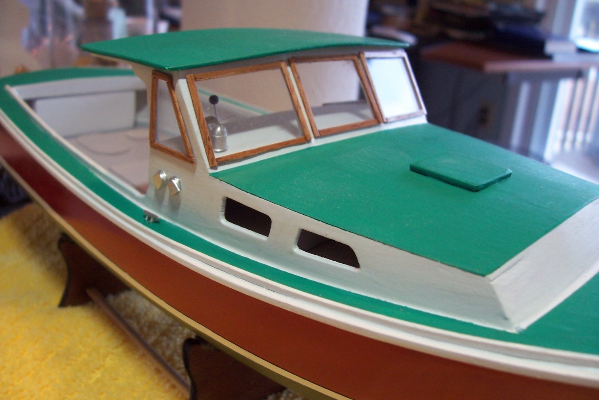
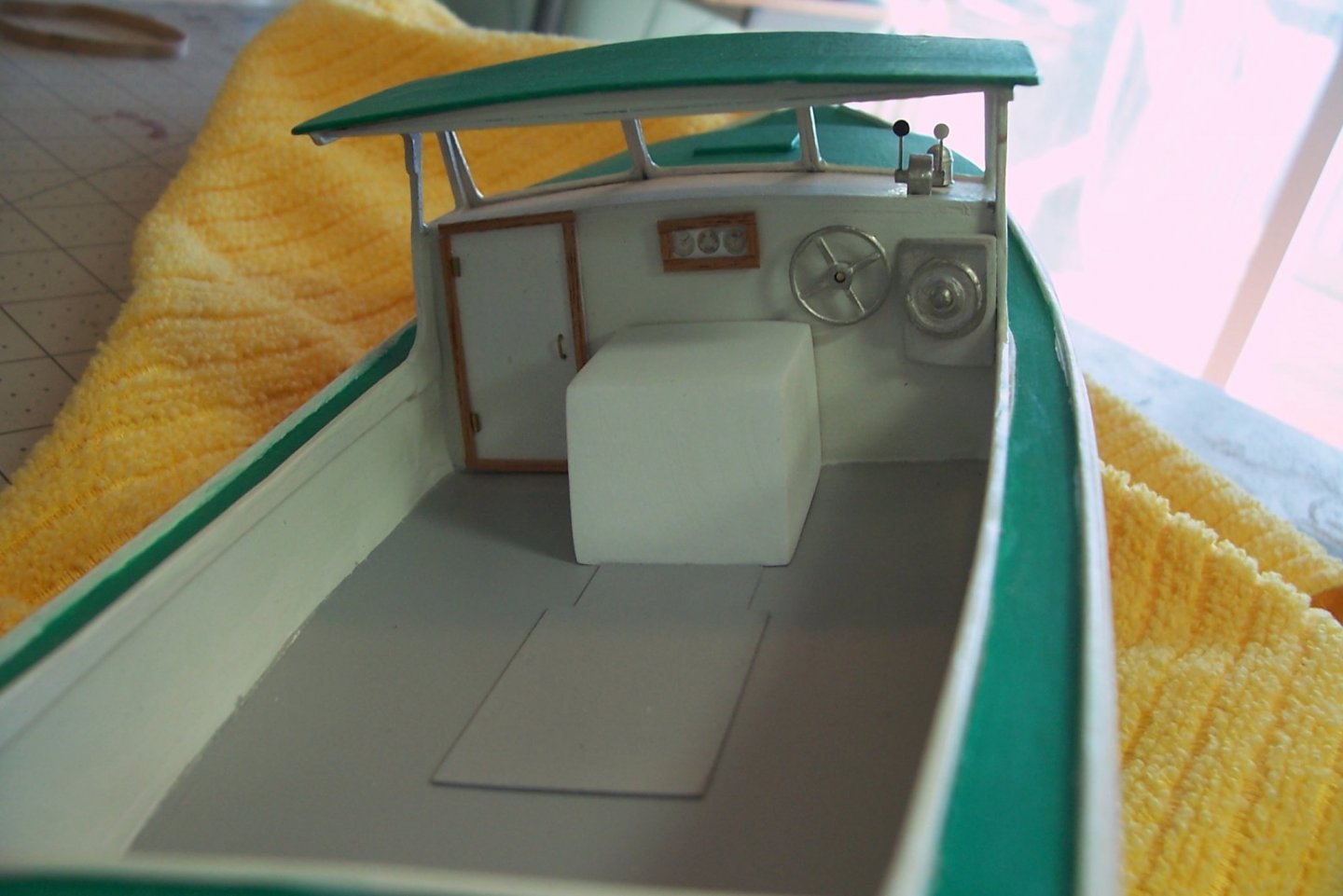
Detailing Now that the painting is done things are moving along pretty quickly. Some of the interior details include the engine cover, instrument panel, engine controls etc. The instructions call for mounting the compass and engine controls on the dash after the windows are installed but it is pretty cramped up there under the roof so I put them in earlier so I could reach thru the window openings to position them. The gages are just a photo from the internet downsized and covered with acetate. When I inventoried the kit upon receiving it I noted that there was sheet plastic for the window - I just assumed it was acetate but it is actually 1/16 inch plexiglass which looks a lot more realistic. It is cut to shape using the window cutouts saved for that purpose. The plexiglass can be cut with a saw to rough shape and then sanding to its final dimensions. They do not have to fit perfectly because the joints will be covered with mahogany strips.

- 20 replies
-
- 6
-
-
- red baron
- lobster boat
- (and 2 more)
-
Taner, you have an interesting build going on here. I have never seen bulkheads like the ones in this kit - should make a very nice model. Keep up the good work.
-
Nice work Keith, it's a pleasure to see this come along. WRT one of your earlier posts regarding the cannon, I'm pretty sure that was a boat howitzer, small enough that it could be hoisted into a boat and carried ashore with a landing party and then moved around on land by hand. If you have every watched a Navy football game on television, they have one that they fire after every touchdown. They are solid brass and look good - as does your model. Keep up the good work.
-
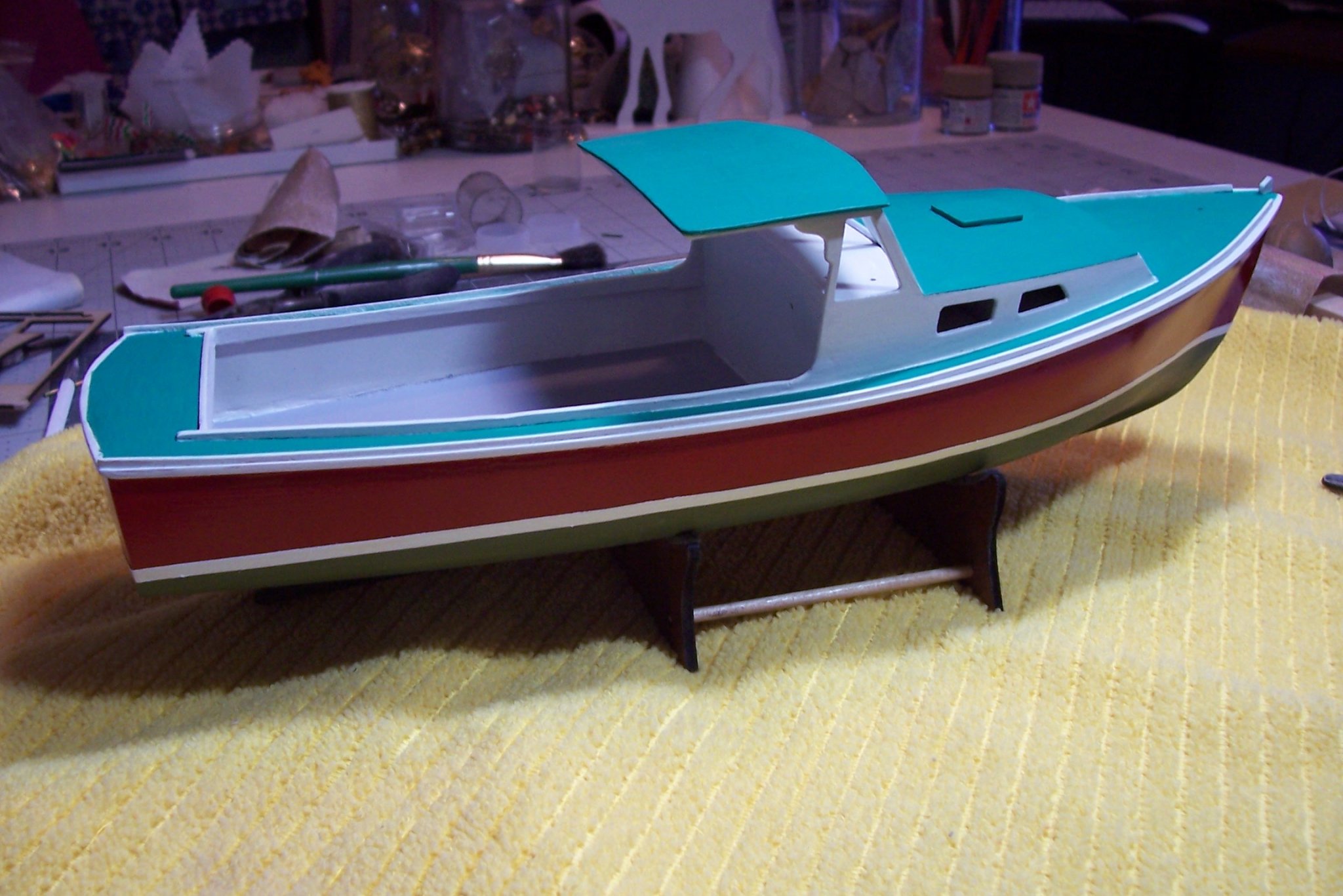
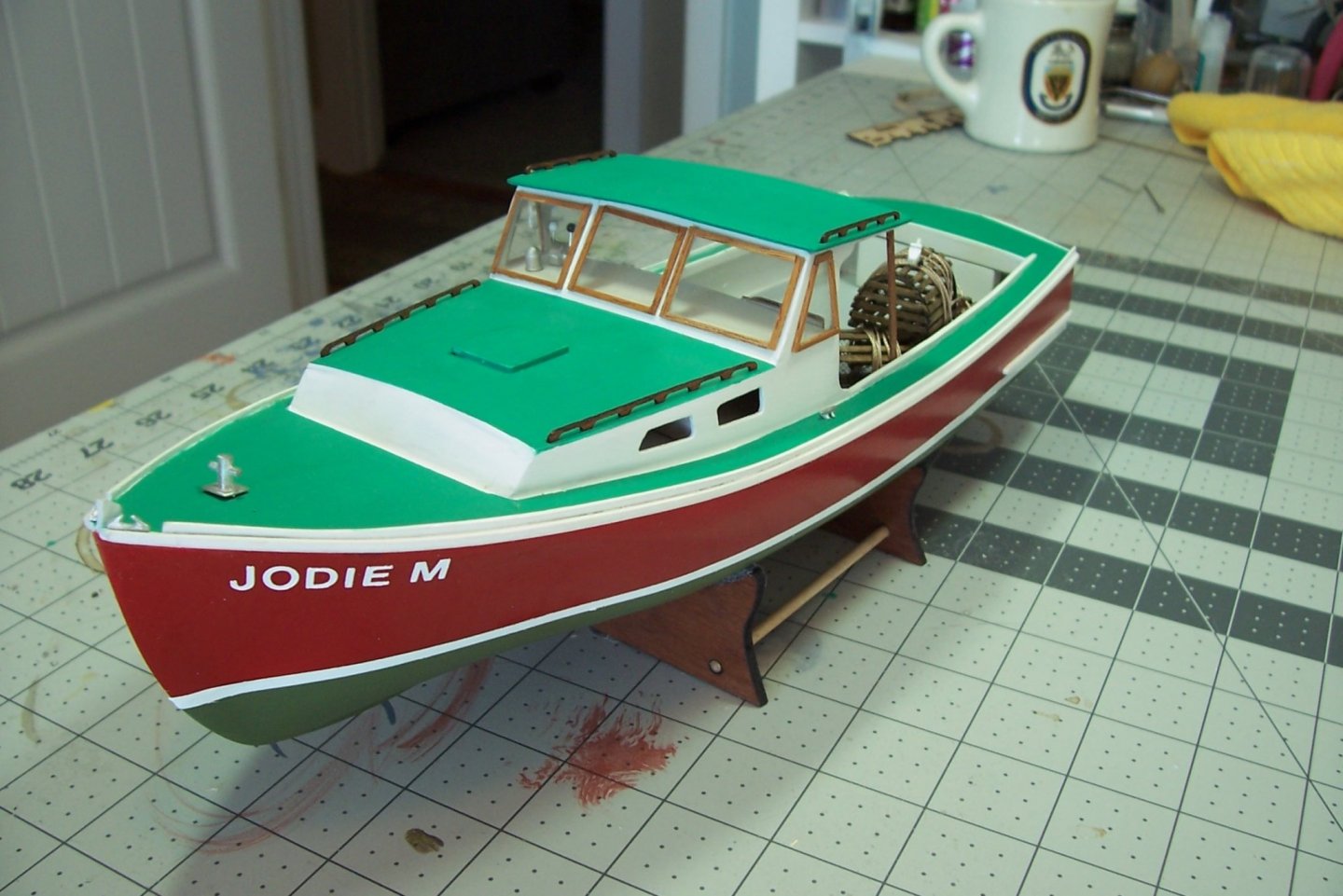
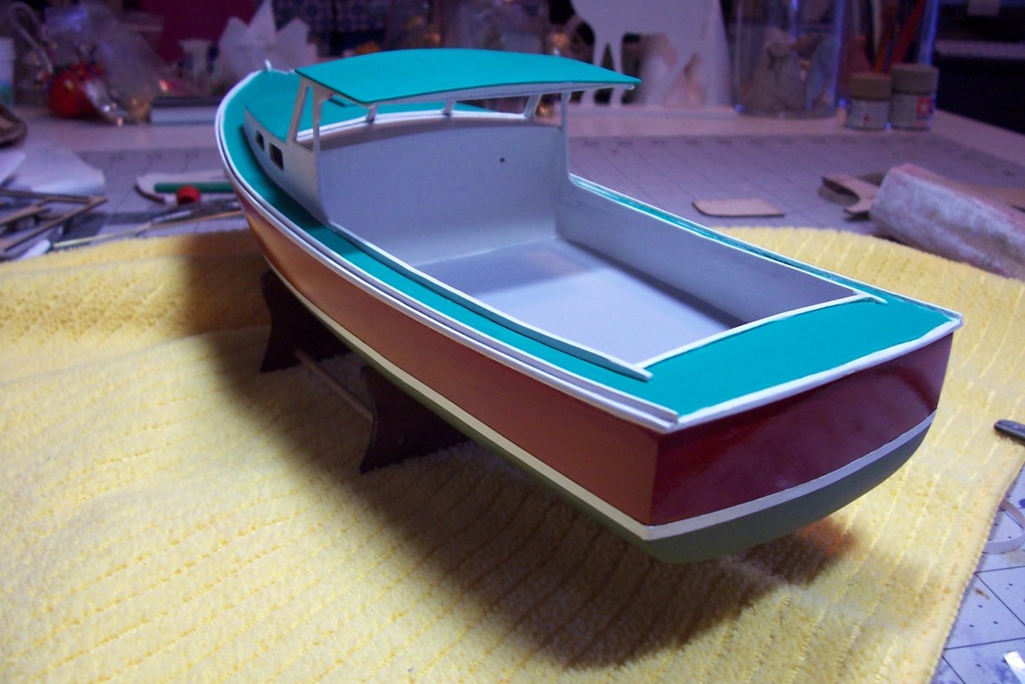
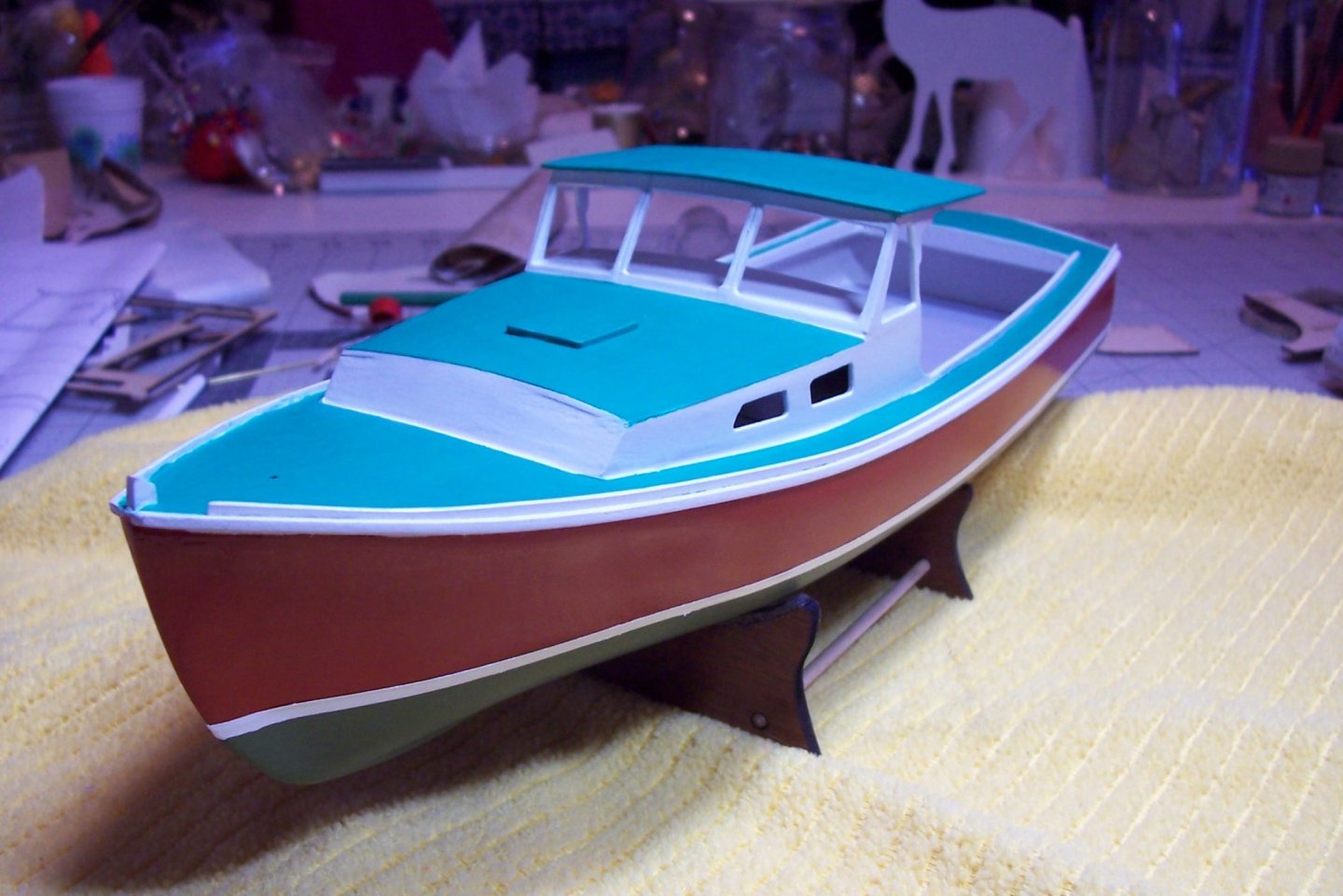
Painting It’s been a while since my last post but it is not because I have not been doing much - it is just that painting this thing is a slooooow process. The kit provides most of the needed colors (the primer supplied is white, not gray, so the cockpit deck was painted with my own primer). The brand provided for all of the colors is True North Precision Enamels, a brand I was not familiar with. For anyone who builds this kit my best advice for painting is if you are good with a airbrush (I’m not) use it. If you brush on the paint as I did make sure to thin it and be patient. It takes about 5 coats to cover white primer and the first 3 look really bad with lots of bleed thru and brush marks. Coats 4 and 5 look a lot better. The paint is also relatively slow to dry so doing 5 coats of each color explains why this took me so long. The white boot topping is kit-supplied pin striping tape. I followed the painting sequence in the instructions and they seemed the most logical way to go about the painting. I did deviate from the kit instructions in the following areas: There are 2 colors of green supplied, both are supposed to be mixed with white or each other to match the colors on the real-world RED BARON. Since I am not building the RED BARON but a generic lobster boat I did not bother mixing the paints - if you do your greens will look different from mine. I used gloss Krylon red enamel spray paint on the hull because I wanted some gloss as some relief from all the rest of the flat paint. That may not be “realistic” but I like the look and since the model will not be cased it will be easier to dust. The instructions recommended using the pin stripe tape to mark the waterline for painting. I did not use it for that, preferring some Tamiya masking tape I had on hand. Next up will be the lettering and then the addition of the details which should go pretty quickly.

- 20 replies
-
- 7
-
-
- red baron
- lobster boat
- (and 2 more)
-
Nice looking Pigs and Otters!
-
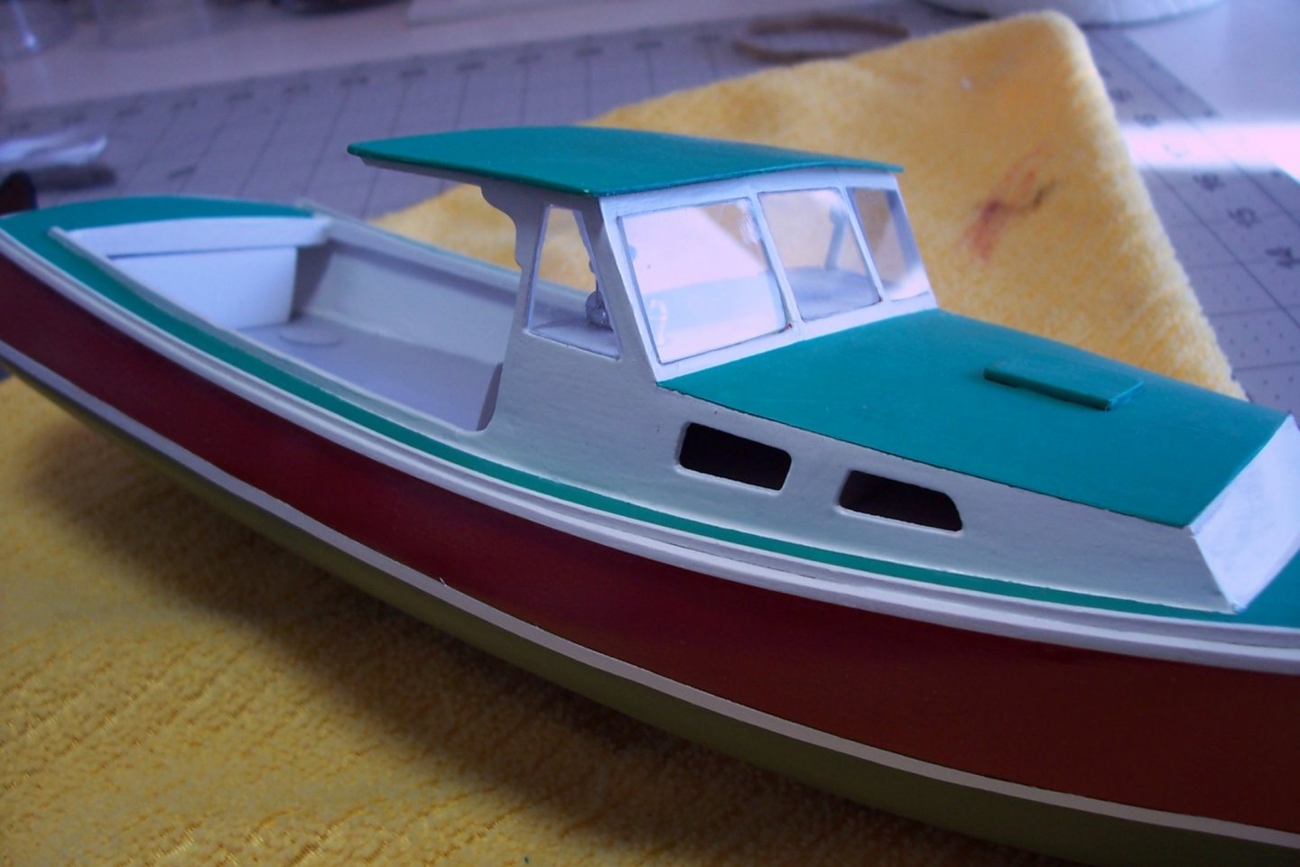
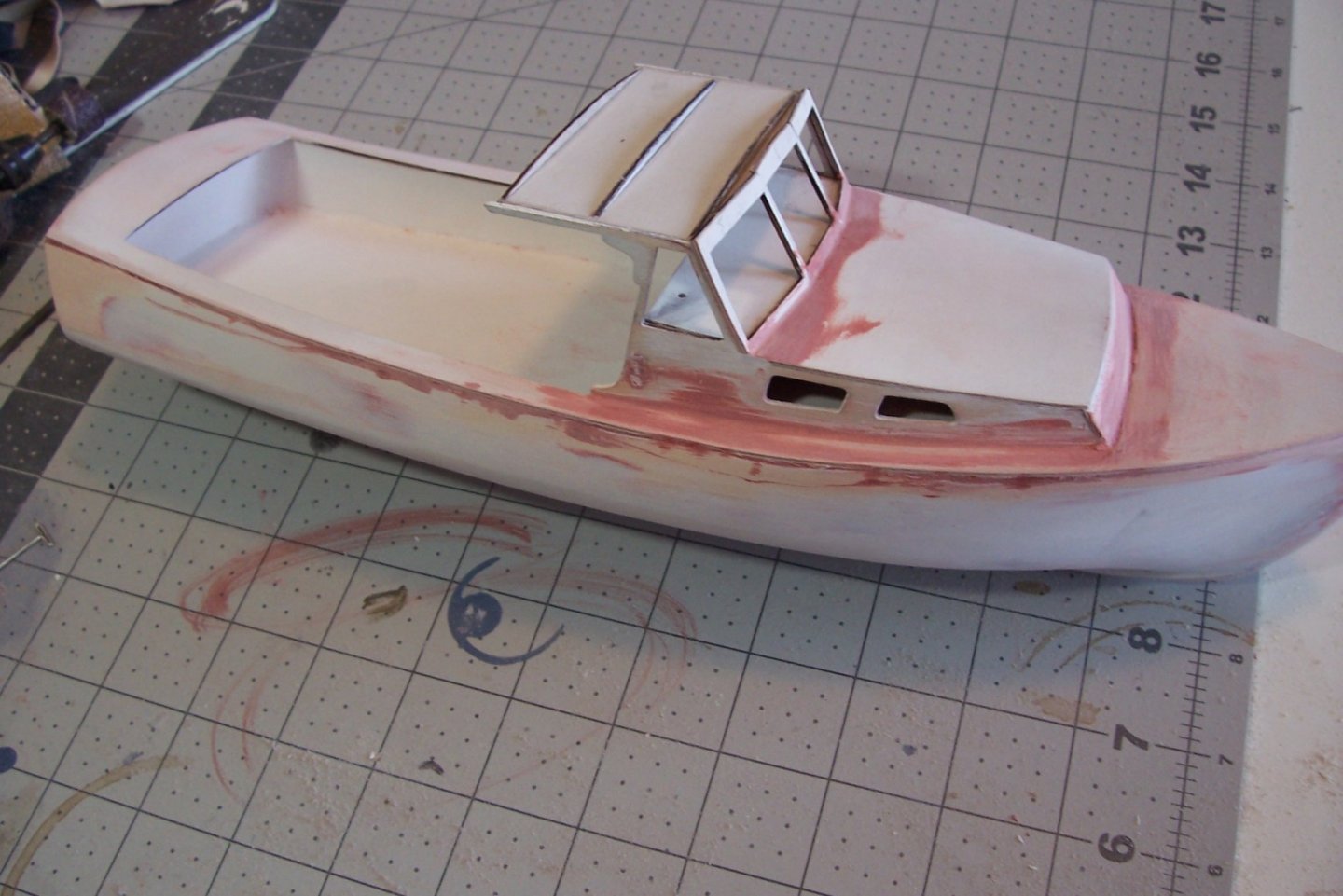
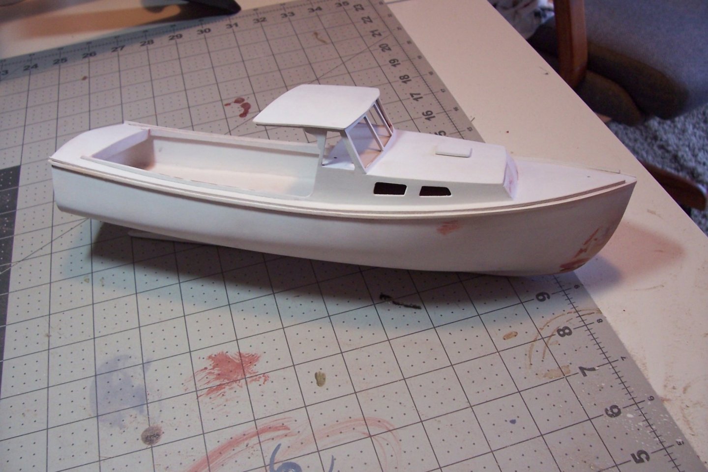
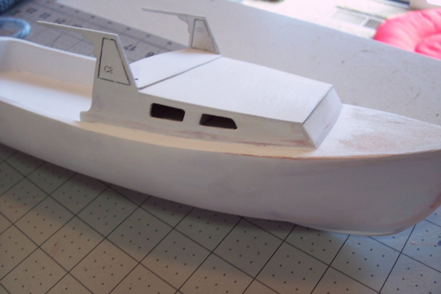
Finishing up the hull The window frames went in OK after a little sanding and adjusting. The inner roof is also on with 3 curved pieces on top that will impart some camber to the top of the roof. Lots of filling and sanding done and more to go. At this point all of the structural work is finished. The 1-piece ply deck is in place, the sheer guards around the top edge of the hull and the toe rails around the outer edge of the deck are also done. There are 3 pieces of coaming around the edge of the well and the pilothouse roof is in place. After a little more sanding and priming it will be time to paint everything.
- 20 replies
-
- 4
-
-
- red baron
- lobster boat
- (and 2 more)
-
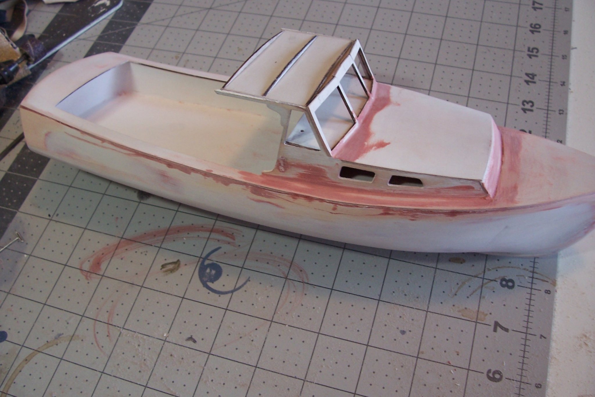
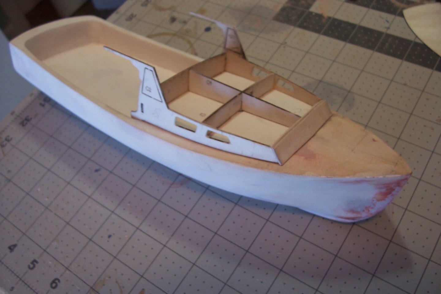
Assembling the cabin The 2 cabin sides and the aft cabin bulkhead hook together with tabs. It took a fair amount of sanding and carving to get the bulkhead flush against the cabin formers. An important step is to do plenty of dry fitting of all 3 pieces to ensure the forward ends reach to the proper point on the deck - any adjustment or trimming of one piece will require adjustments on the other 2. Bottom line: I spent a lot more time than I had planned on what I thought would be a simple step. The cabin top went on easily. The piece of ply laying on it between the raised portion of the sides it the former for setting the angle and slope of the window frames. The instructions recommend leaving the cut-outs in the window frames for support until all the work in the area is done.

- 20 replies
-
- 3
-
-
- red baron
- lobster boat
- (and 2 more)
-
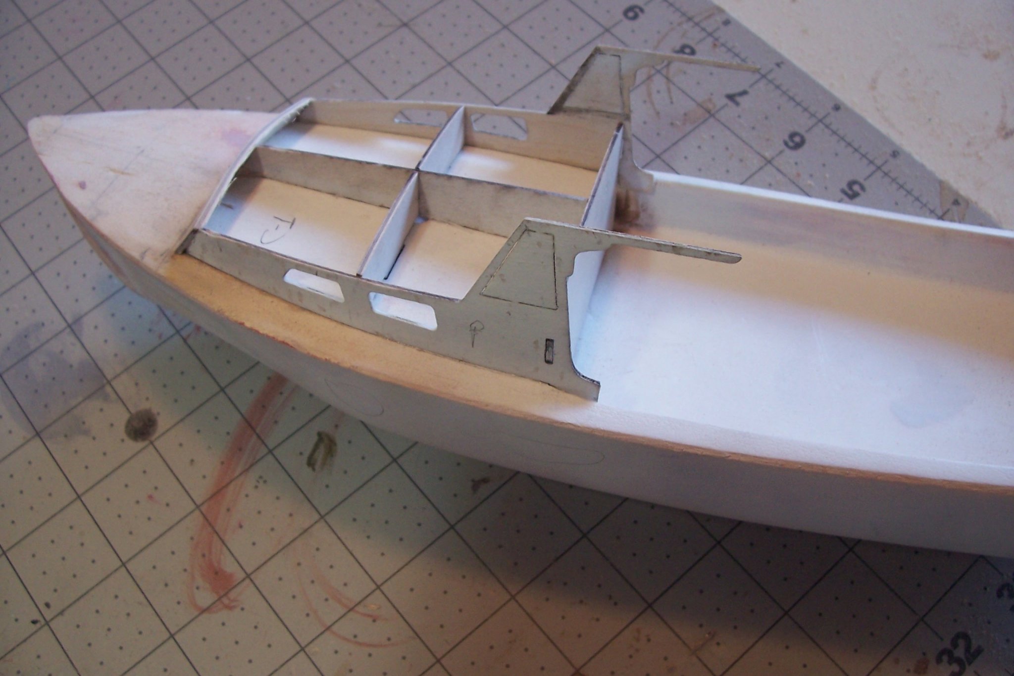
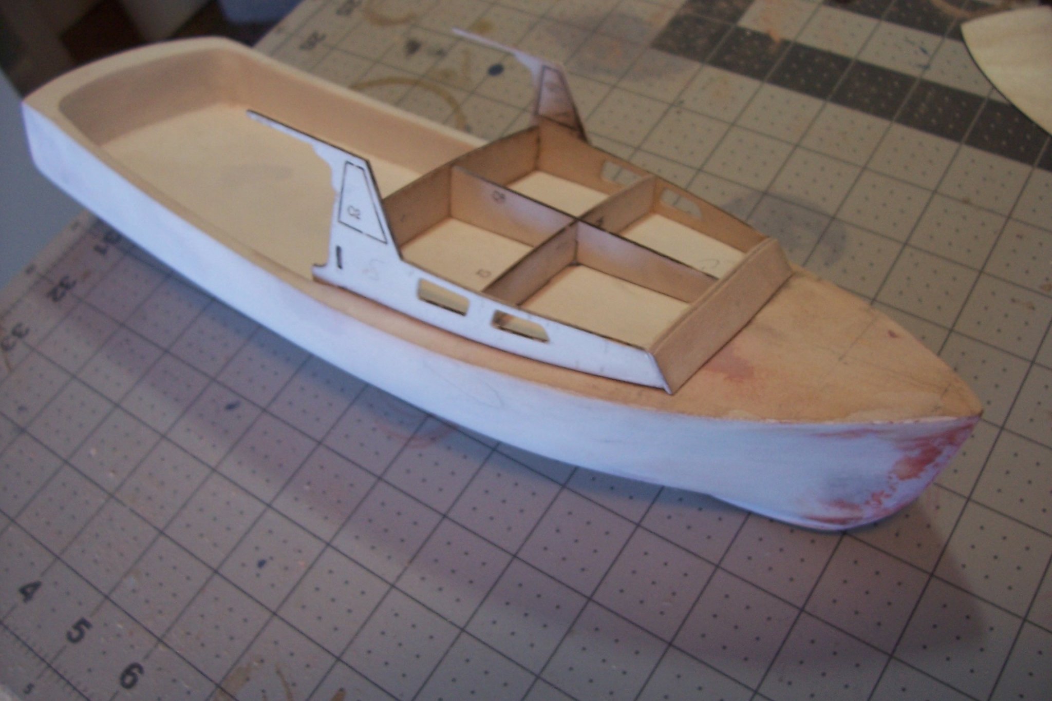
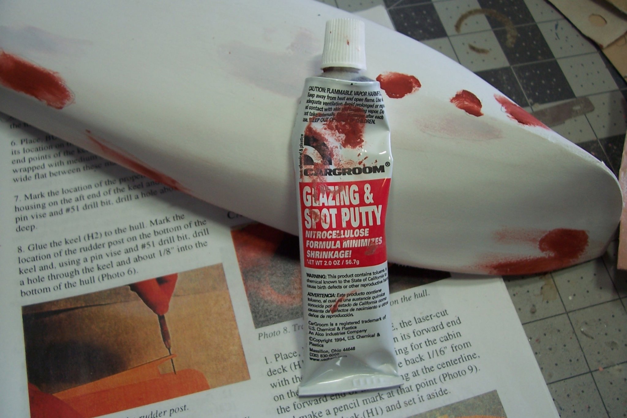
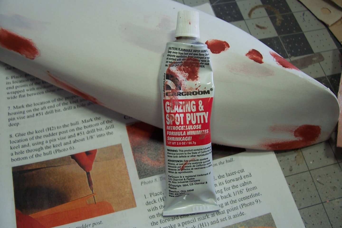
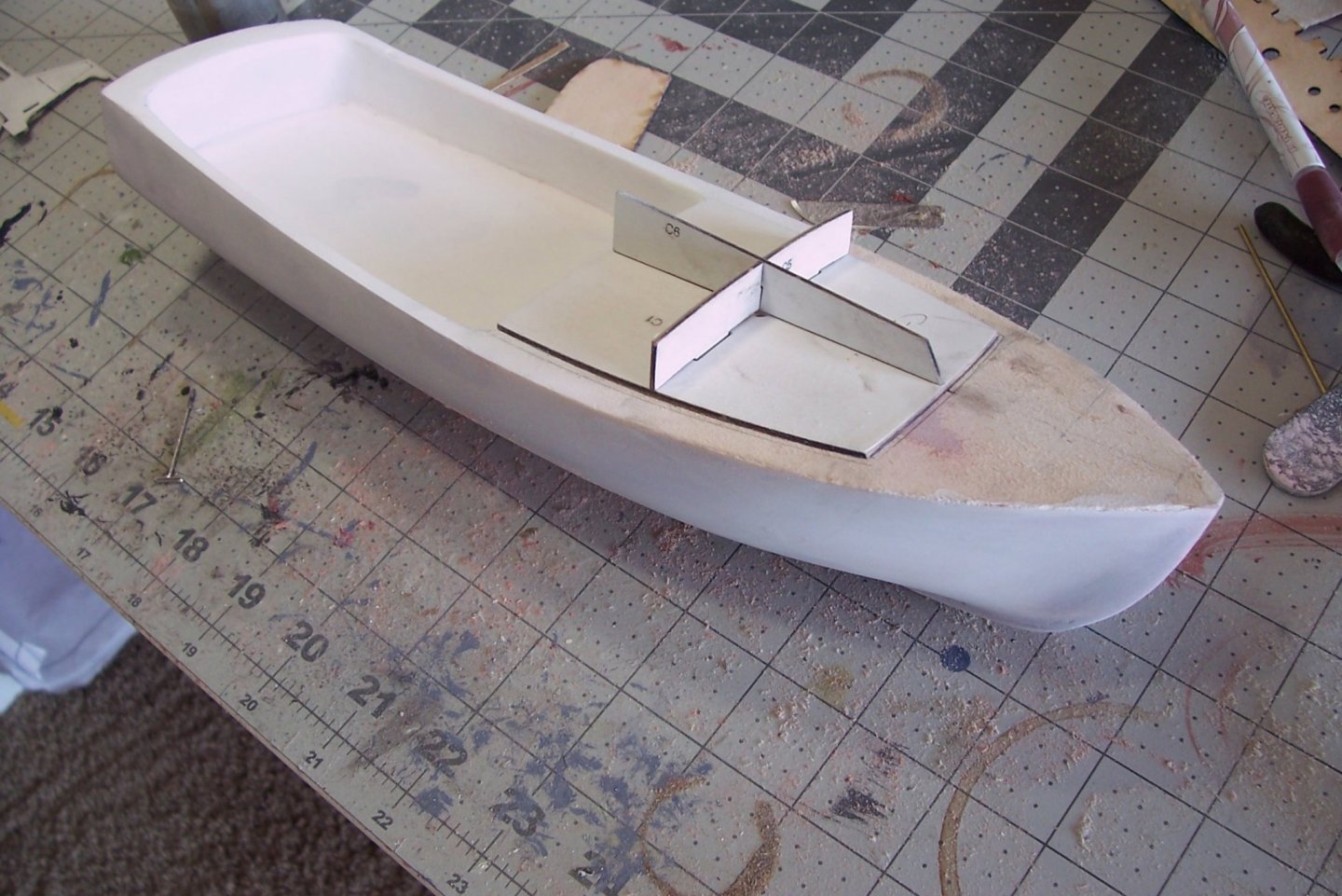
Smooth sanding the hull I’ve got a new BFWF!! (Best Forever Wood Filler) I went to Auto Zone to pick up some more Bondo for a wood filler. They did not have any but they did have this stuff so I thought I would try it. It’s Great! Unlike Bonds there is no need to mix in any hardener - just squeeze a little where you need it and spread it around with your finger tip. It adheres to the wood as well as Bondo, dries pretty quickly and sands as easy as the bass wood. Nice stuff. After using sandpaper, primer and the wood filler to get the hull as smooth as possible I attached the keel. A little sanding on it’s mating surface was needed to get it to lay on the hull, in contact all along its length without having to apply pressure. After gluing it in place I thought I had better pin it because I could see myself breaking it off while working on the deck. I drilled 4 holes thru the keel and about 1/4” into the hull and filled them with tight-fitting brass rod. The joint feels very strong now. With the keel in place I was able to sand it and the bow fair and then go thru the smoothing process again. My last addition was the 3 pieces of ply that will shape the forward cabin and serve as its interior bracing. The deck has not been smoothed because it will be covered by a piece of laser cut ply.


- 20 replies
-
- 5
-
-
- red baron
- lobster boat
- (and 2 more)
-
Nice build! Great painting. Mind if I ask how did you paint the bridge windows? Did you hand brush them with dark paint and then go back and touch up the frames with haze gray?
- 89 replies
-
- 2
-
-
- independence lcs-2
- trumpeter
- (and 2 more)
-
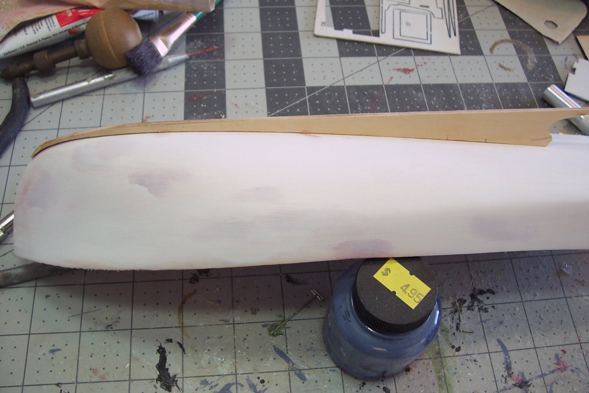
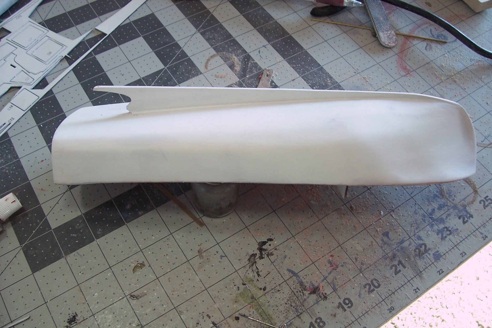
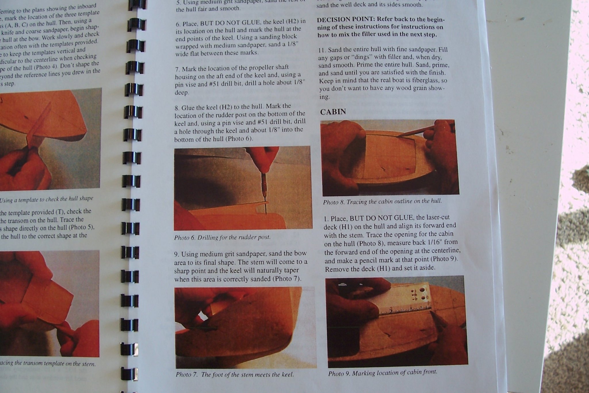
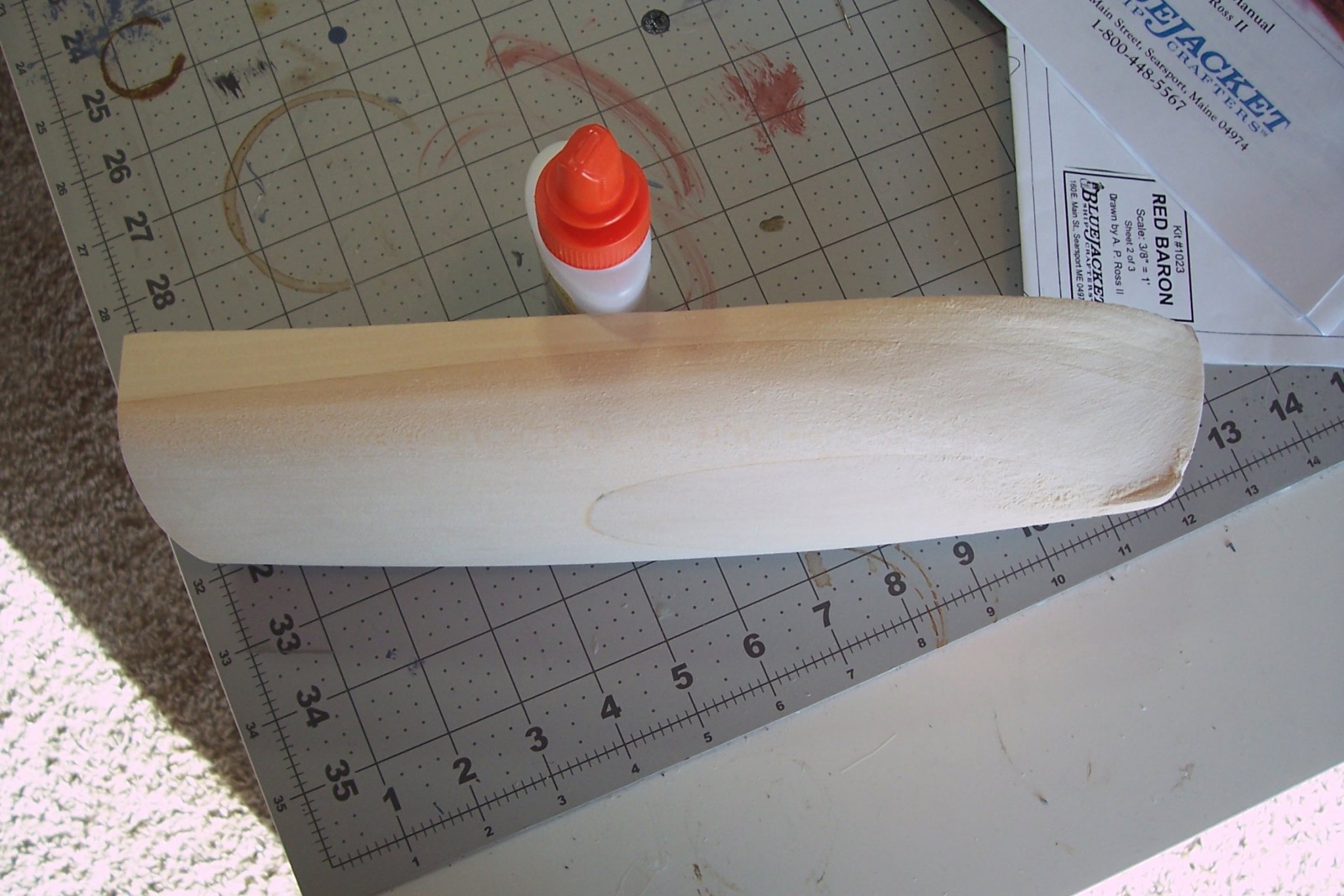
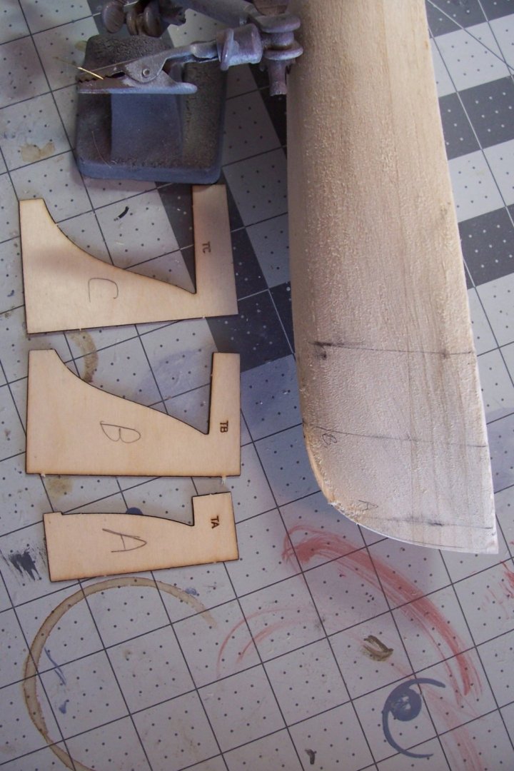
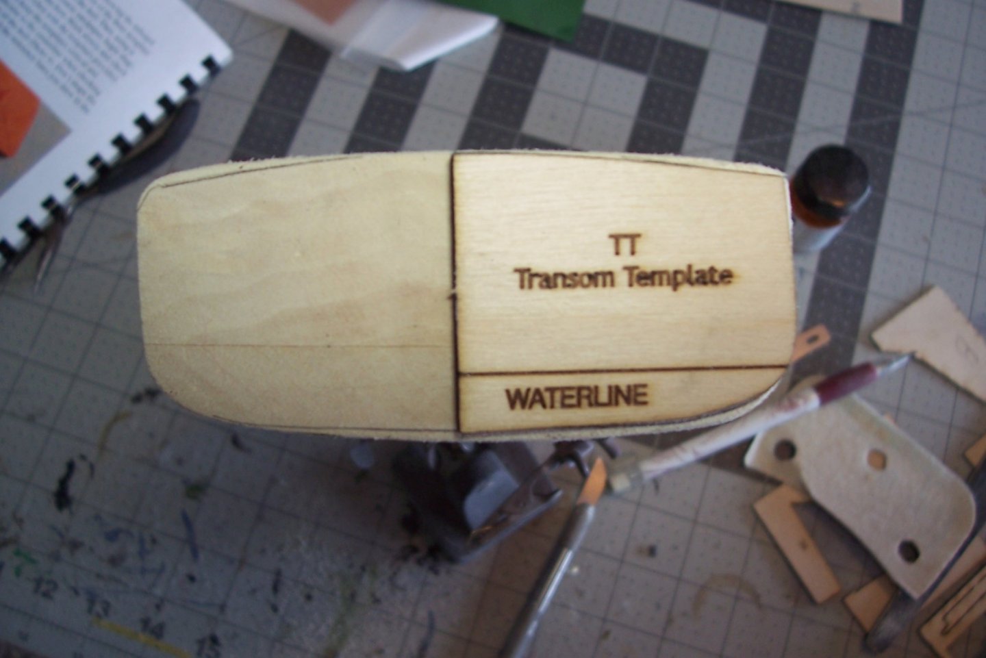
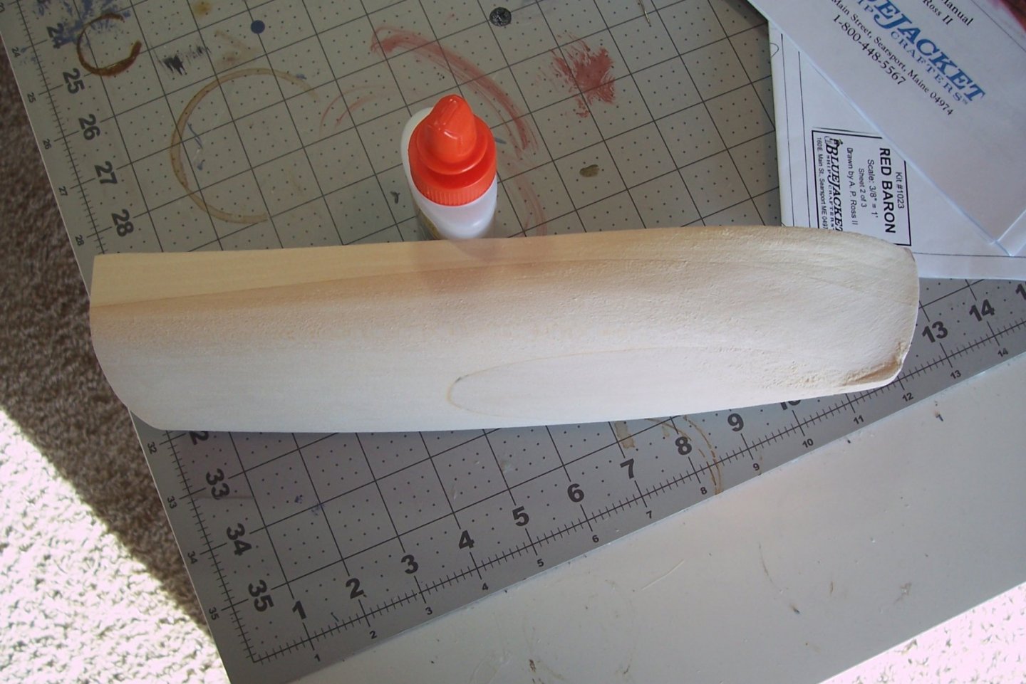
Sanding to shape Although it has been a while since my last post I have NOT been spending all this time sanding! I have been doing a little most days, in 5 or 10 minute increments since it bores me but all told I have probably spent about 2 hours bringing the hull into the proper shape. The kit provides 3 laser cut templates to shape the bow area, mostly to impart a flare to the bow. The template stations are only about an inch apart so don’t try to do just one at a time - you need to sand the whole area and keep checking your progress using all 3 templates. The kit recommends using a sanding block and/or a hobby knife. I’m a very poor hand at carving (I’m more of a gouger than a carver) so I stuck with sandpaper wrapped around a paint bottle for the big curves and wrapped around the handle of a hobby knife for the smaller radius areas. The stem has not been brought to a fine edge yet because the keel must be added first and then it and the hull are sanded fair together so it blends in. There is also a template to shape the transom (don’t toss it when you are finished with it - you will need it later to mark the waterline location). As can be seen here some wood needs to be removed from the upper and lower outboard areas. Now that the hull is in shape I have to do more sanding (and priming) to get a smooth finish that will replicate the look of fiberglass which is what the real boat is made of.


- 20 replies
-
- 3
-
-
- red baron
- lobster boat
- (and 2 more)
-
Thanks for the kind words - I was a little surprised to see this build log stagger out of deep storage like a zombie.
- 22 replies
-
- 2
-
-
- kirk
- orange hobby
- (and 4 more)
-
Hey Brian, boy am I glad I found this build! I usually spend all my time over on the kit page. You are doing a heck of a job. This really brings back a lot of memories for me - I served on ADROIT (MSO-509) up in Little Creek 88-90. Most fun I ever had. If you have time you might spend it googling around on MSO crew reunion websites, they can have a lot of good, close-up onboard photos that can help with detailing. NAVSOURCE.ORG and the Naval History and Heritage Command website both have a ton of photos with the NHHC site more likely to have onboard shots. Keep up the good work.
-
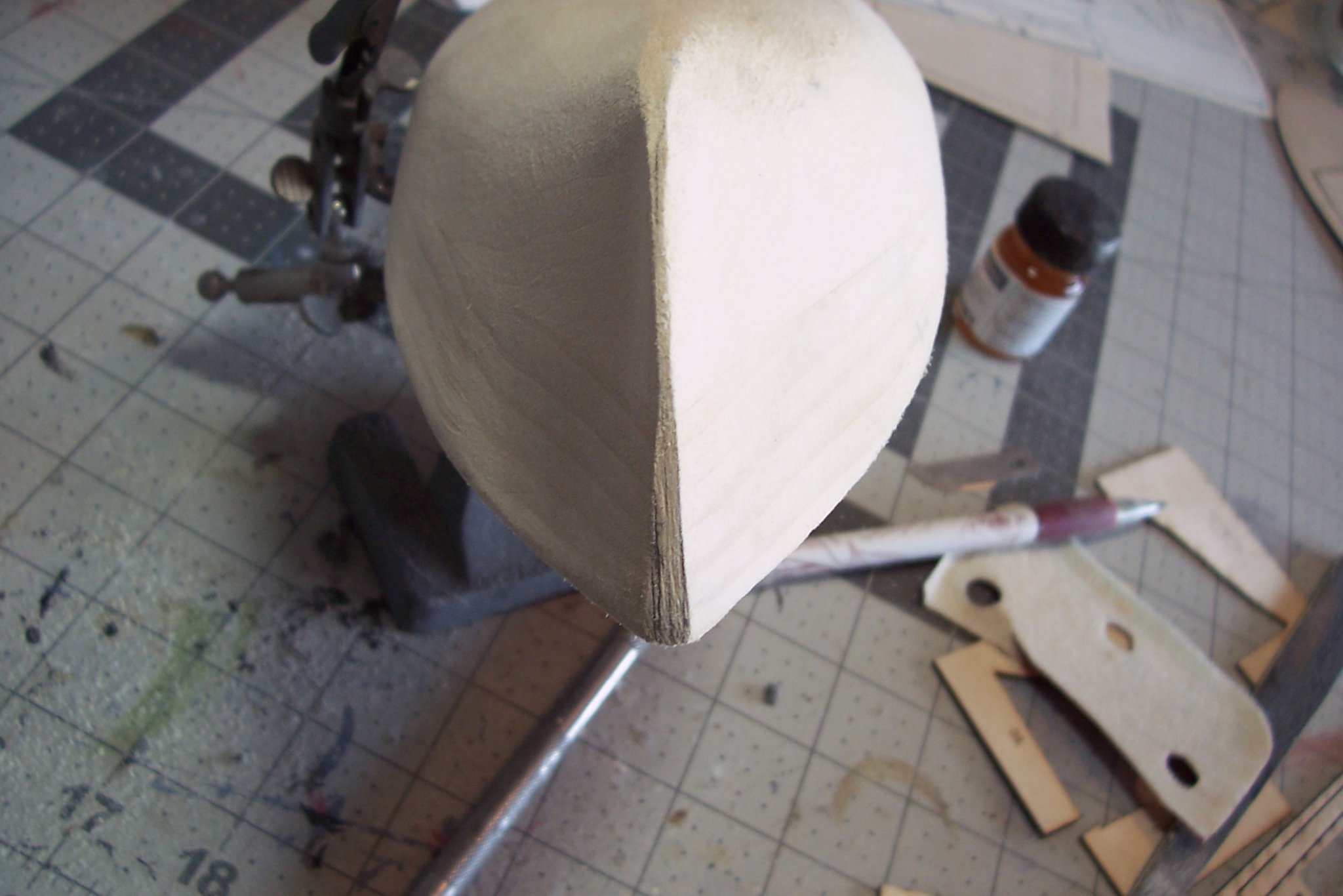
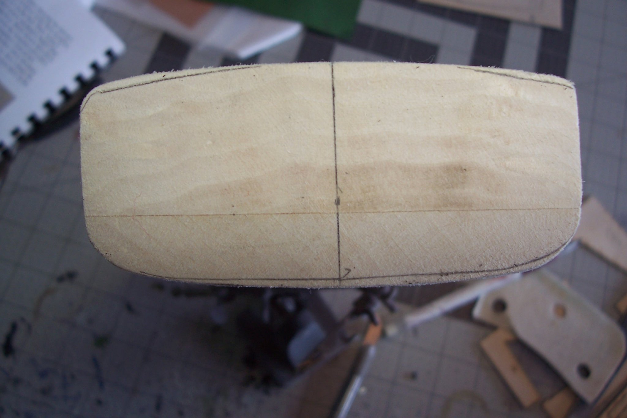
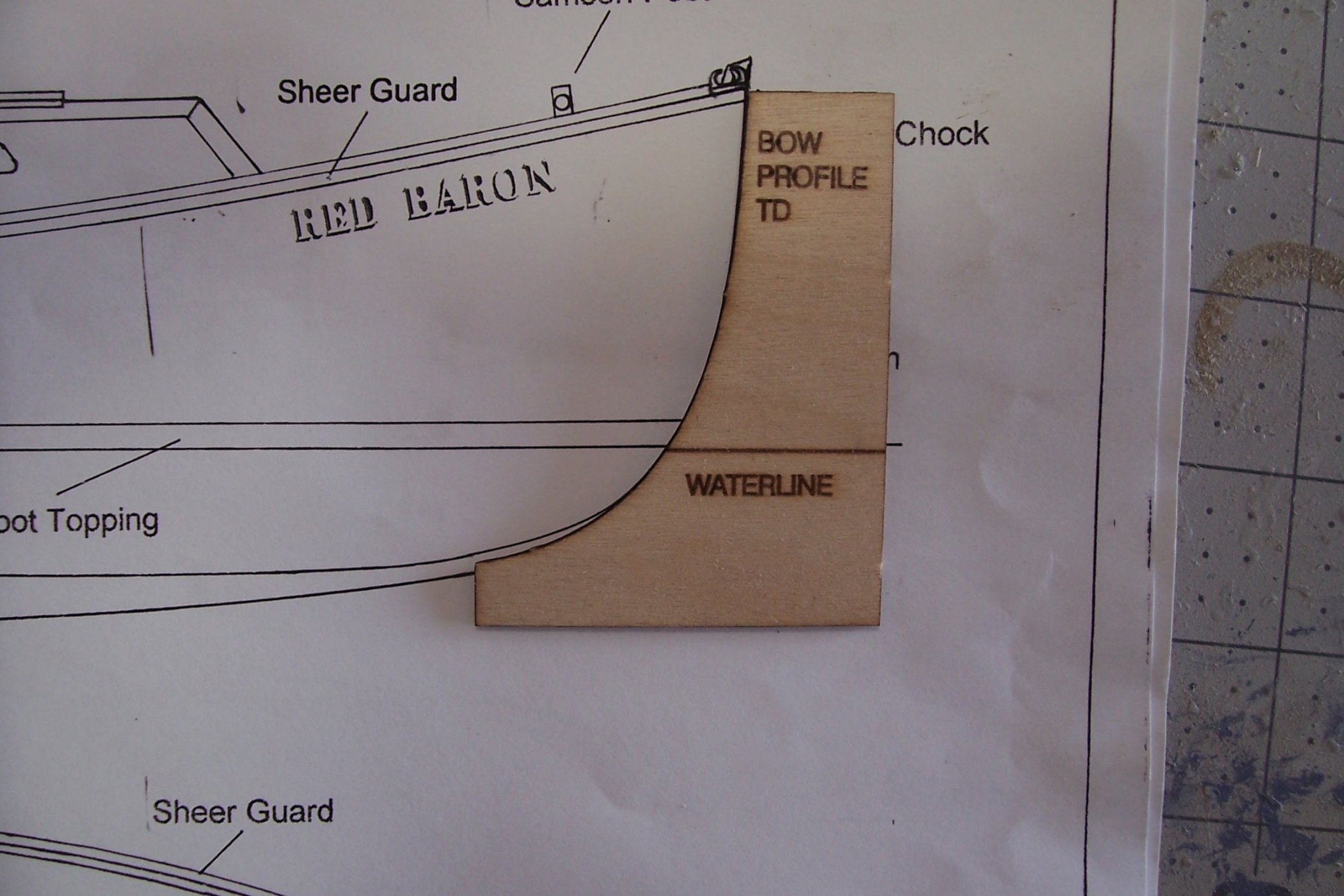
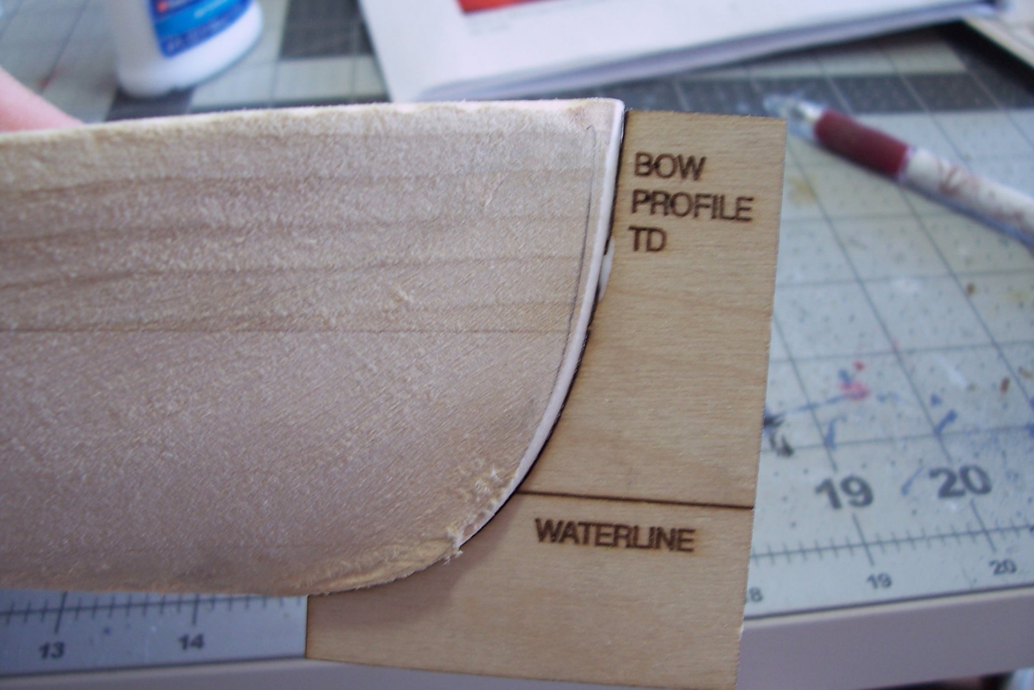
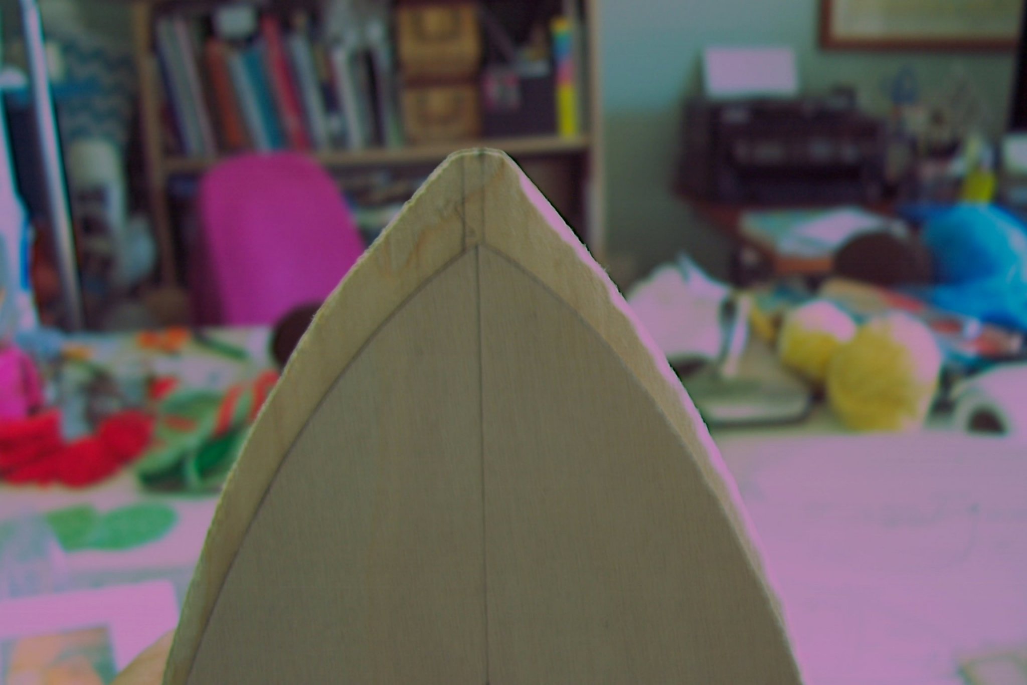
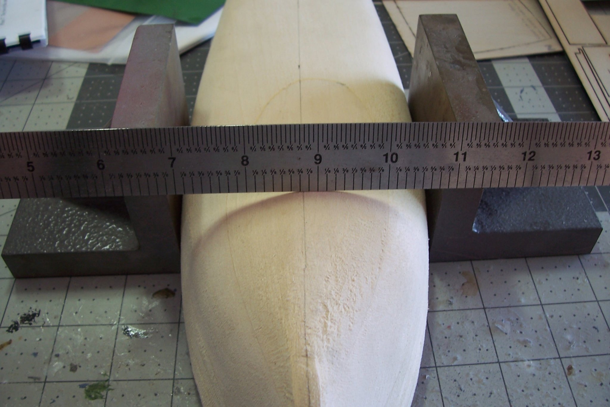
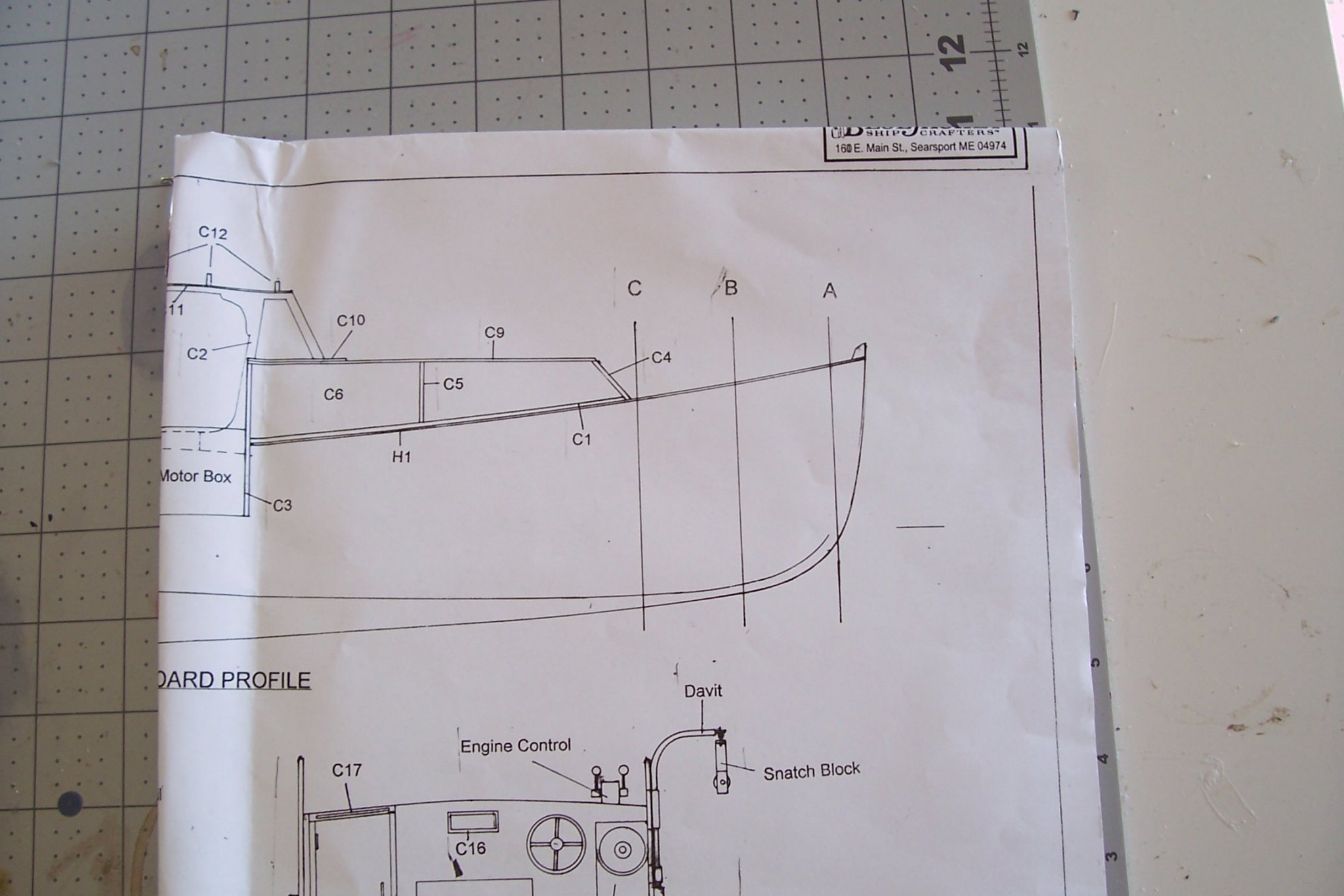
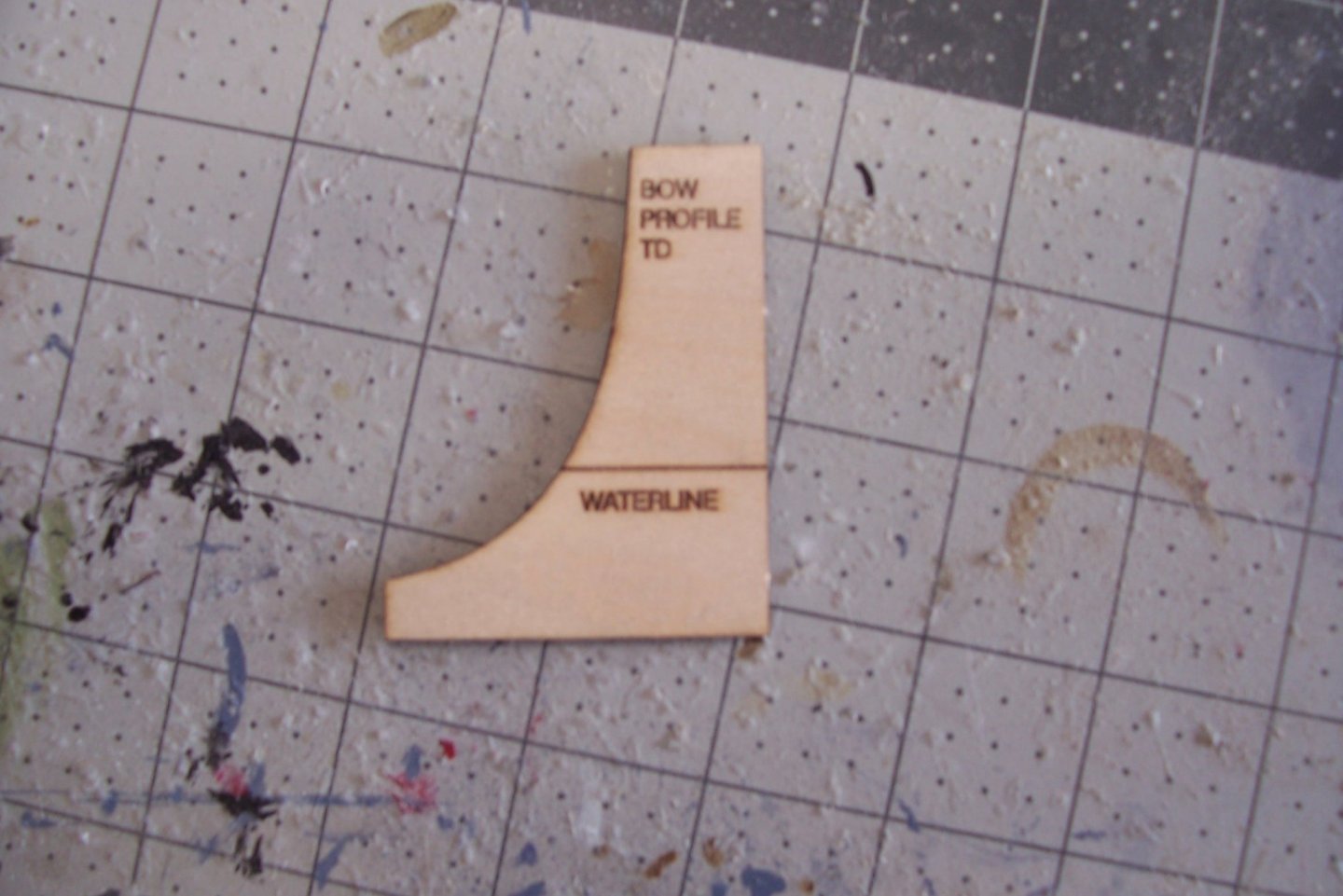
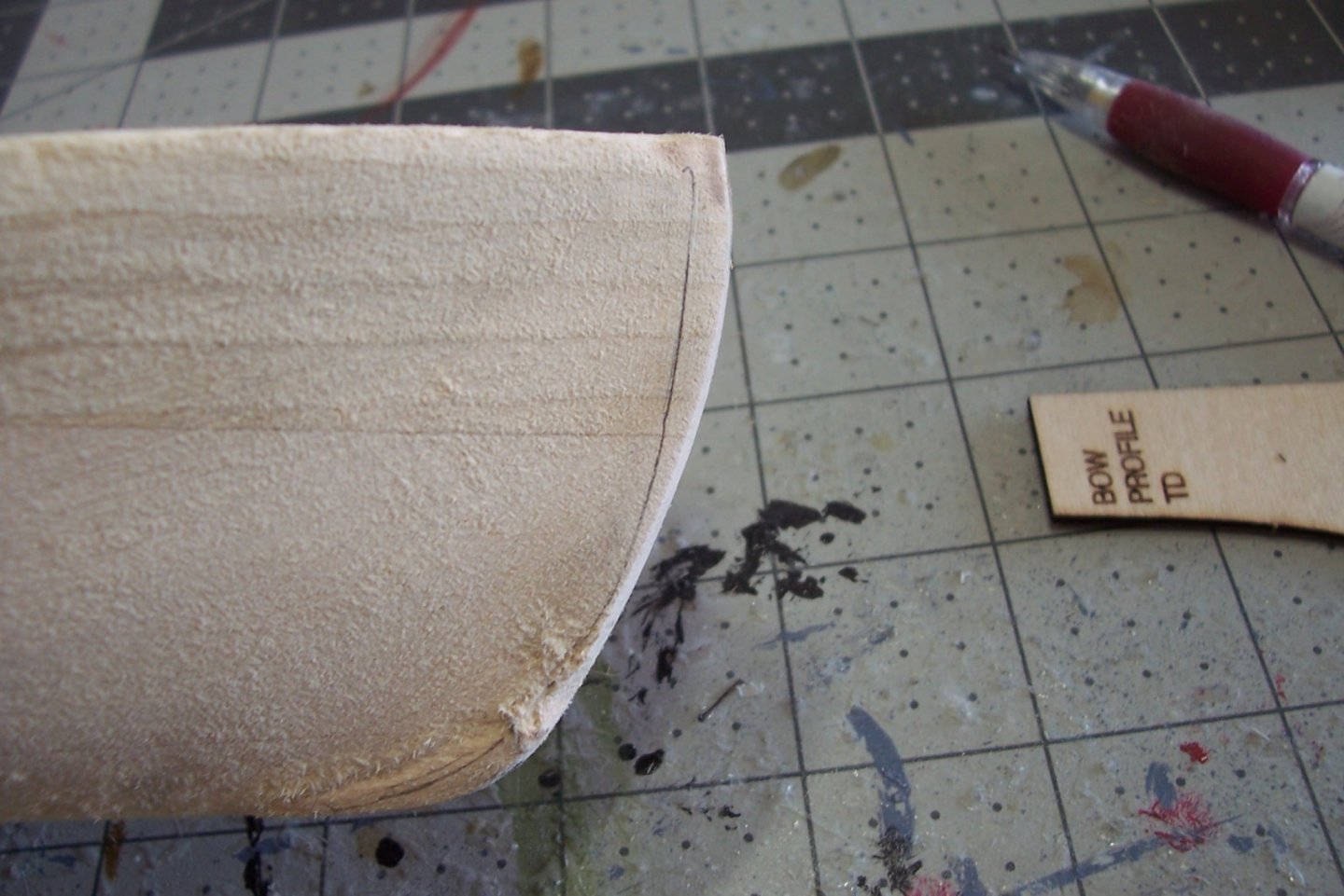
Shaping the stem and marking the centerline The first steps on this build are to prime and sand some of the delicate laser cut pieces for the cabin interior while they are still on the fret, the instructions point out that they would be hard to reach after assembly so now is the time to do them. The next step is fairly simple, shaping the stem. The kit provides a laser cut template for the stem. Since BlueJacket advertises this kit as appropriate for beginners as their first solid hull kit I thought I would explain in more detail than usual my thought process for the steps involving shaping the hull. There are different ways to do it, this is just my way. The first thing I did was to check the template against the plans and see how and if it fits. The fit was fine; the top of the template, the waterline mark, and the curve all matched the plans just fine - if they did not then I would have had to decide which one to go with. It is not as simple to check the hull against the plans but when the template is laid on the hull there was plenty of wood. The only cautionary note is that when you lay the template on the plans you can see how important it is to keep the template plumb when checking your sanding progress, if it is cocked just a little then that will affect the line of the stem and the height of the bow. It’s worth a little time to study how the plans relate to the un-sanded hull and to visualize what it should look like when finished. I used the template to mark it’s outline on the hull - it will not necessarily be the final sanding line but it serves as a warning line not to sand beyond it without malice aforethought (i.e. make sure you really need to go that far, chances are you will not.) As the instructions say, go slow with the sanding and check your progress with the template frequently. It doesn’t take much time or effort since this basswood sands easily with a sanding block. When done my template fit snug to the stem (I tacked glued it in place here just to simplify trying to take a photo without have to hold 2 pieces of wood at the same time.) The next step is to mark the centerline on the main deck, stem, keel area and transom. While it sounds simple you really need to take your time on this one - screw it up and you will have a world of problems getting the hull to look right. As I found out if your results don’t look right chances are they are not right. I measured from side to side a multiple points along the deck and drew a line connecting them. At the bow the line was almost 1/8” to one side of where the center of the stem was by eye. After several more tries the results were the same which meant I would have to sand quite a bit more wood off of one side than the other and based on my experience with solid hulls from BlueJacket, that didn’t sound right. BJ’s hull shaping equipment has always provided me with symmetrical hulls. That’s not to say that all areas of the hull need the same amount of sanding or that all kits are the same but all of them in my experience require the same amount of wood removal port and starboard of the centerline at any given point on the hull. At that point I decided to check the laser cut deck piece against the hull. By measuring from side to side and marking the centerline of the deck piece I confirmed that it was symmetrical and that the centerline intersected the sharp bow point dead center so I new that the deck piece (in effect a template at this point) could tell me if the hull was symmetrical. When played on the hull the deck fit perfectly, it matched the side of the hull along its whole length and its centerline was about 1/8” of an inch off of my marked one, and more importantly it lay on top of the centerline of the stem. Obviously my centerline of the hull was off. I tried measuring a new centerline by holding the hull between angle blocks and figured out that the source of my problem was that the deck edges on the hull were not as distinct as on the deck template. Making new measurements using the blocks resulted in a centerline that matched that of the deck template and all is right in the world again. Here is the hull with the old, wrong centerline to the left and the deck “template laying on the new, correct centerline to the right (OK, almost laying on it, it moved while I took the photo, it does lay right on it, trust me). Here is how I remeasured the correct centerline using the blocks. Well that’s enough typing, time to get back to sanding.


- 20 replies
-
- 3
-
-
- red baron
- lobster boat
- (and 2 more)
-
Wonderful build, hard to believe it is only your second one!
- 60 replies
-
- 1
-
-
- mary taylor
- solid hull
- (and 2 more)
-
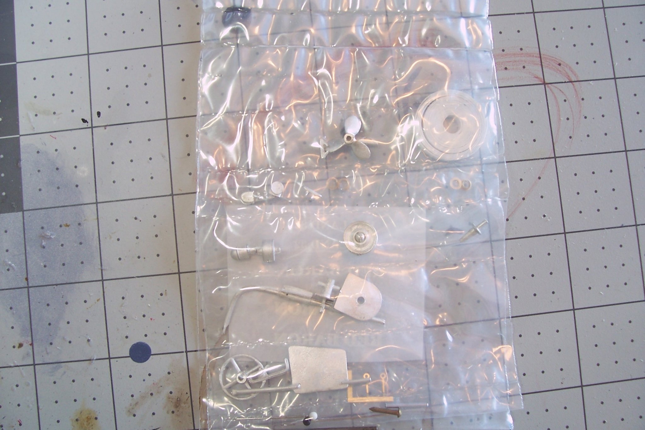
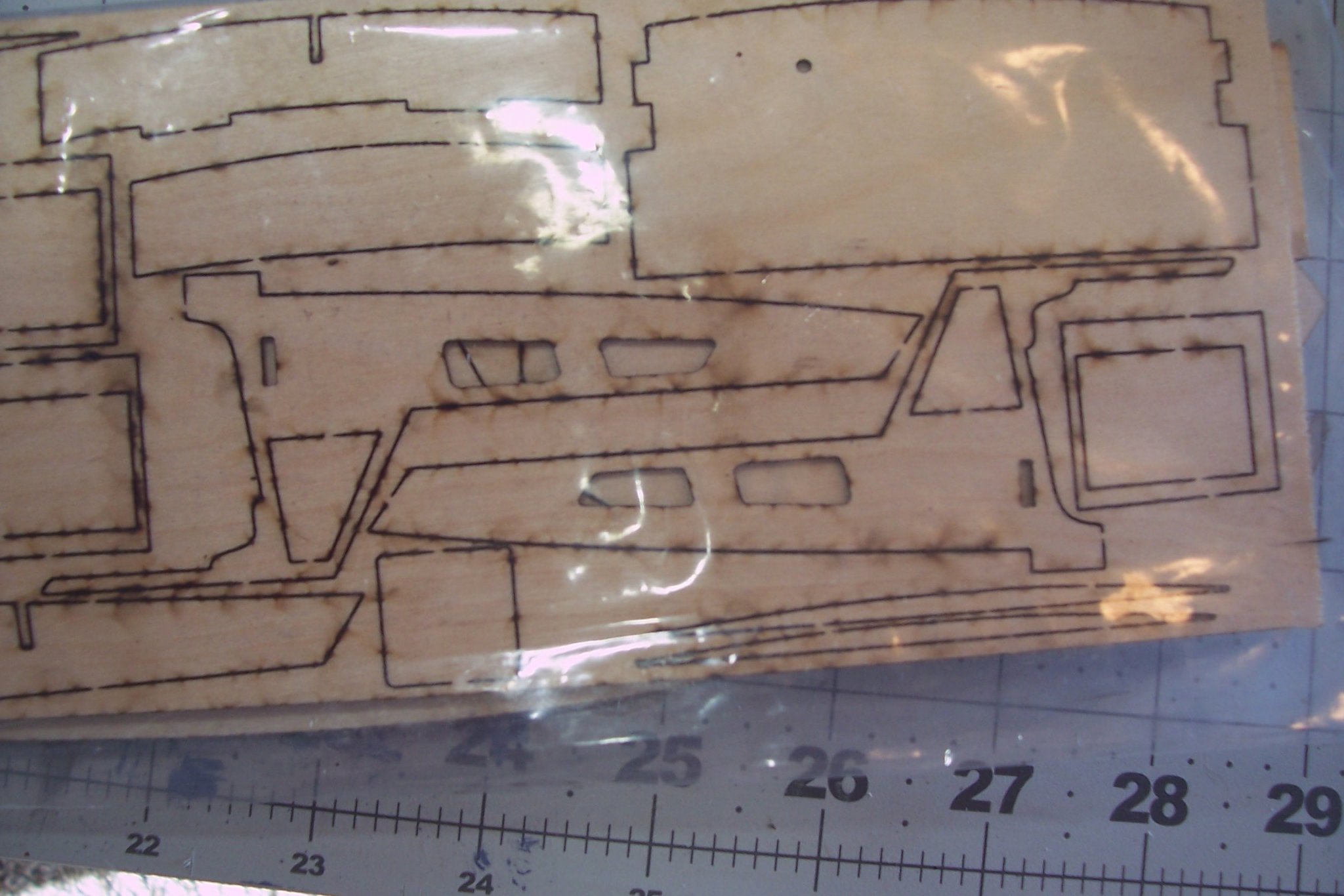
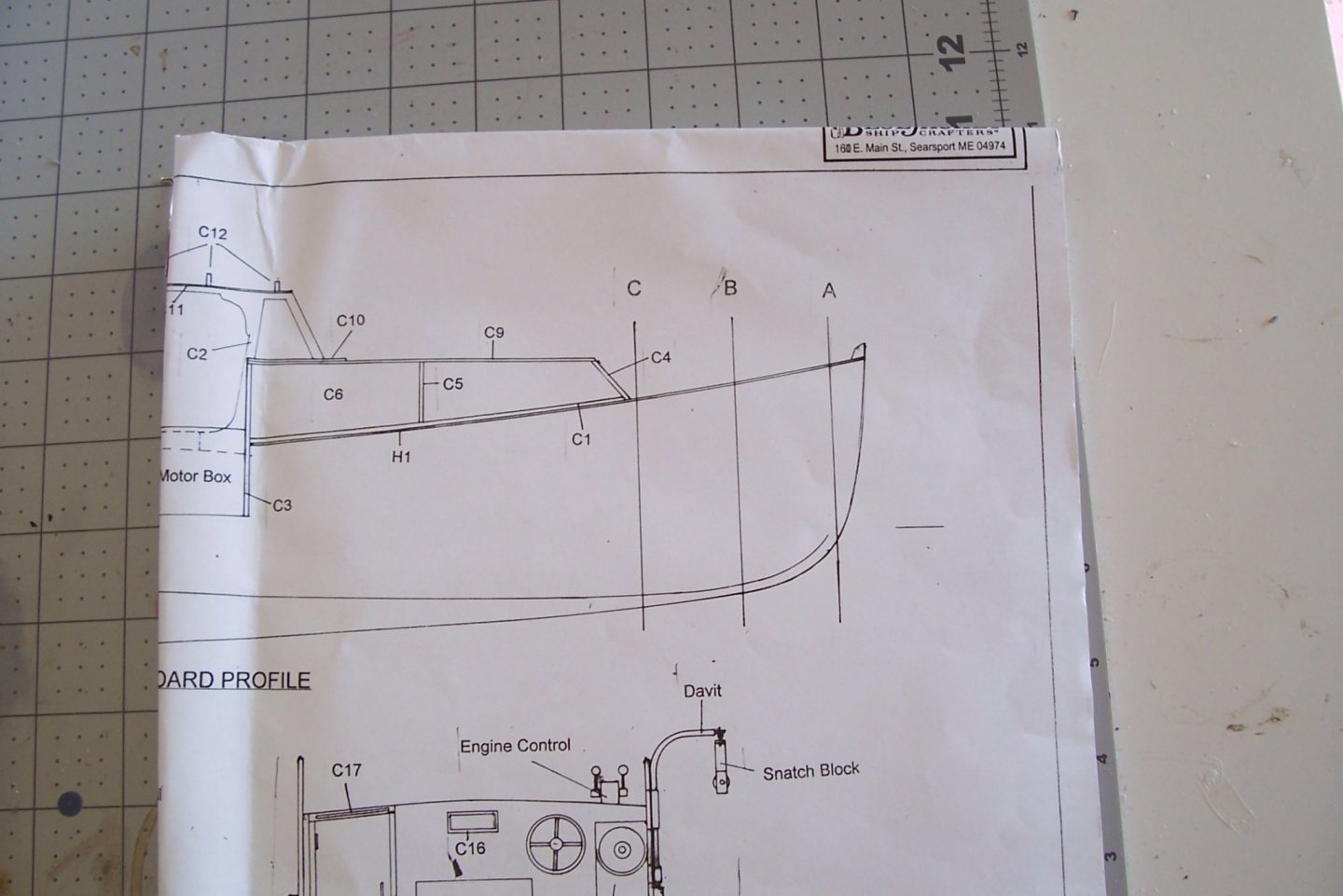
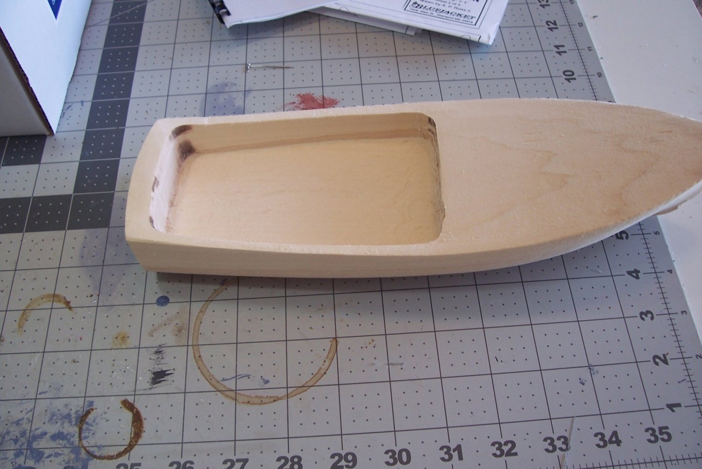
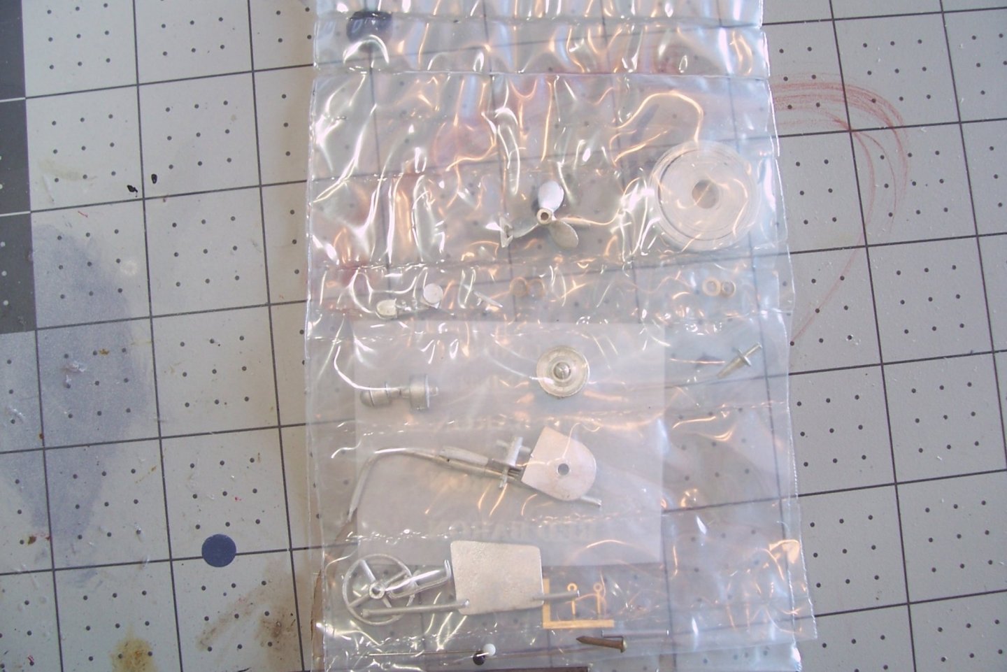
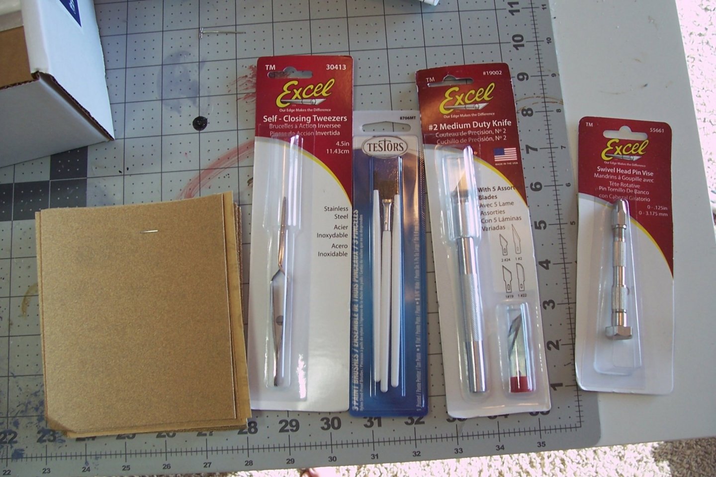
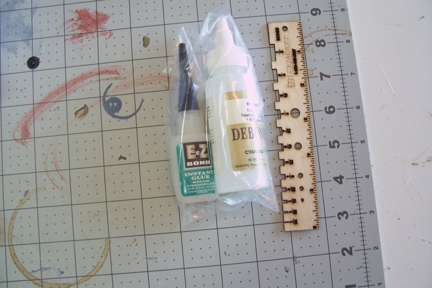
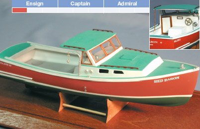
I decided on this kit for my next build because it will, if finished in time, become a Christmas gift for my daughter and son-in-law, both of whom enjoy eating lobster and vacationing in Maine. I'll probably put granddaughter's name on the finished model. I decided to do a build log because as far as I can find out this kit has never had one. Bluejacket sells 3 different lobster boat kits; this one which is 12’’ long, a 23” POB/POF kit, and a 3 ft honker with a fiberglass hull intended for RC. I went with this size because it will fit neatly on a bookshelf. The Red Baron is famous in lobstering circles, she won a lobster boat race a few years back, clocking in at a record 57 knots! I’ll show what’s in the box but if you are interested you can go to BlueJacket’s homepage and click on the “What’s in the box” tab where a video of this kit is shown, along with some shots of the completed model. Plans - one sheet of plans showing side and overhead views and the layout of the laser-cut wood pieces Instruction book - Bluejacket rates this kit as appropriate for beginners so the instructions are more detailed than what I am used to from their more advanced kits. The instructions tell you what to do, how to do it and provide warnings where needed to help prevent mistakes. There are also a lot of photos and drawings. Pre-carved hull: The hull already has its basic shape and the cockpit area is carved out so this should only take a little sanding to bring it into its final shape and then to smooth it up for painting Laser cut wood: Most of the wood provided in the kit is laser cut, including several templates that will be used to check the final shape of the hull near the bow and the curve of the stem. Metal fittings: A bag of brass and britannia metal fittings is provided, giving this kit more detail than I expected. Tools and supplies: The kit comes with basic tools like a hobby knife, sand paper, a pin vise with 2 drill bits, tweezers, a wooden ruler, and paintbrushes. Medium CA glue, debonder and all required paints are included. There is also a bag of white powder which I could not figure out until I read the directions - it’s wood filler that can be mixed with water. Lobster traps: Material and instructions to build 3 lobster traps are included.


- 20 replies
-
- 2
-
-
- red baron
- lobster boat
- (and 2 more)
-
Thanks for the kind words Ian and Cog, I had a lot of fun with this one, hated to see it come to an end.
- 227 replies
-
- 2
-
-
- BlueJacket Shipcrafters
- Stephen Hopkins
- (and 2 more)
-
Thanks Mike, It IS a fantastic kit, so good that I was able to spend my time doing what I like, which is detailing, instead of having to "fix the kit"!
- 227 replies
-
- 2
-
-
- BlueJacket Shipcrafters
- Stephen Hopkins
- (and 2 more)
-
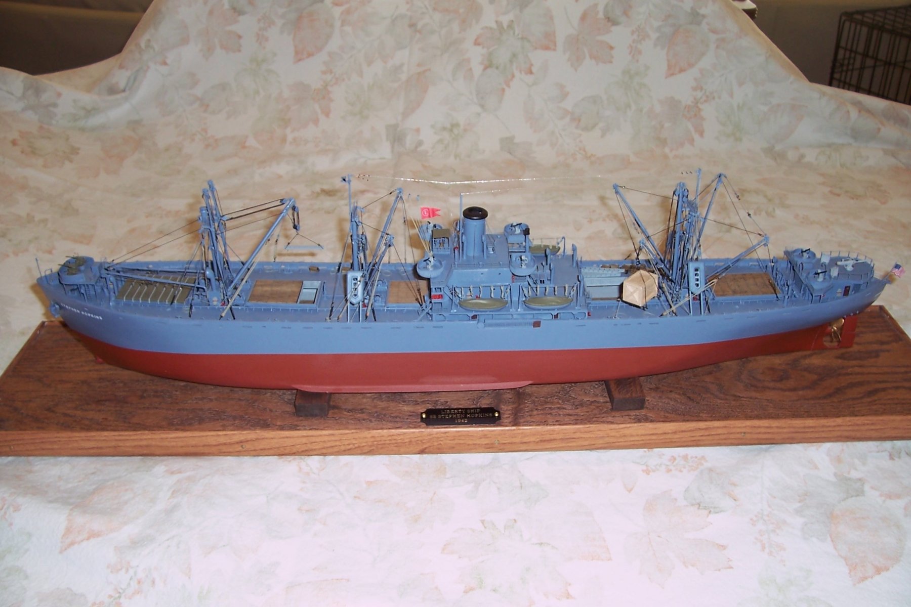
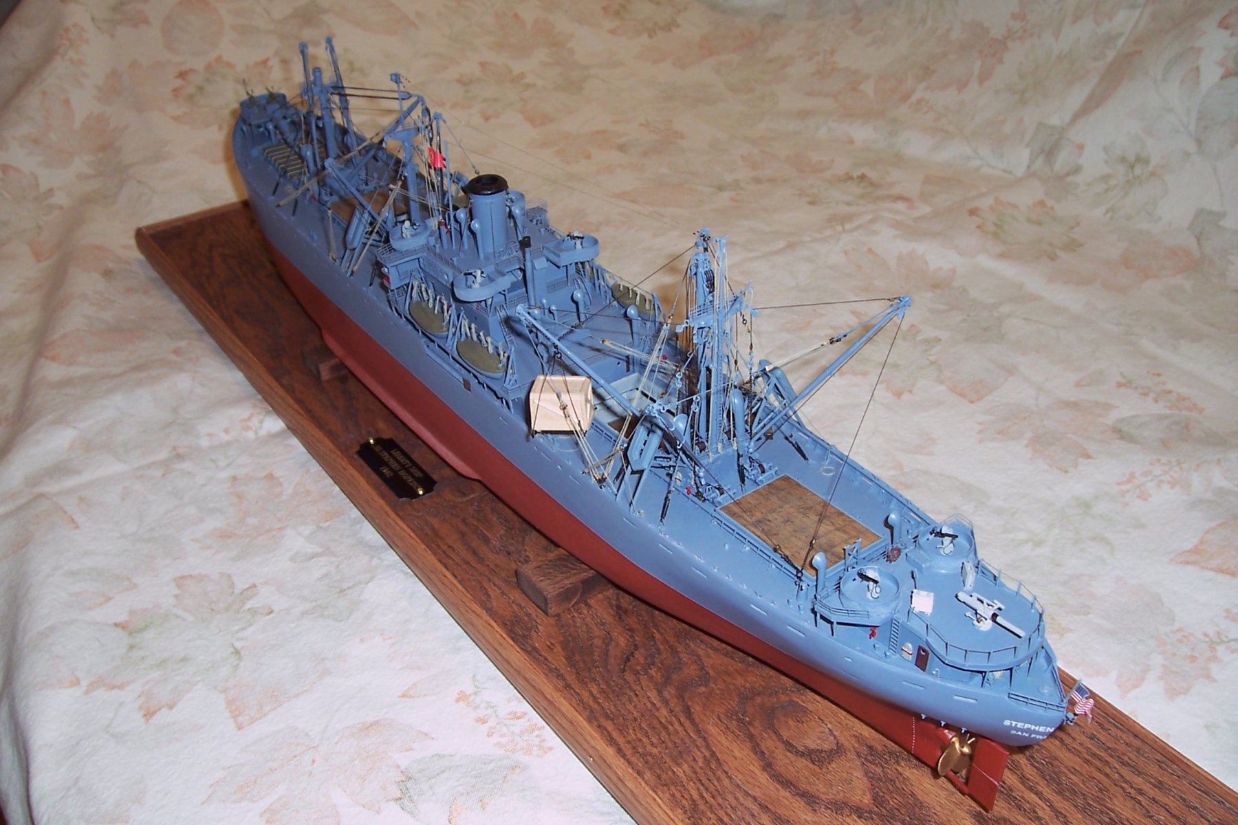
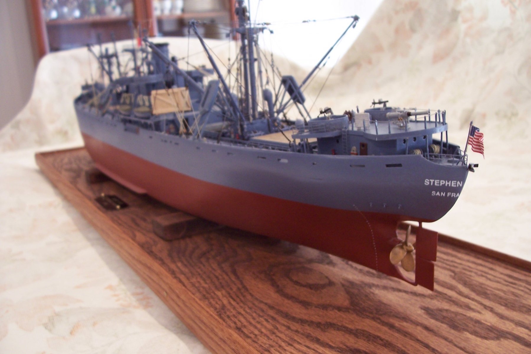
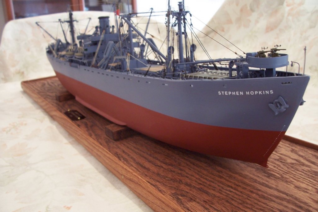
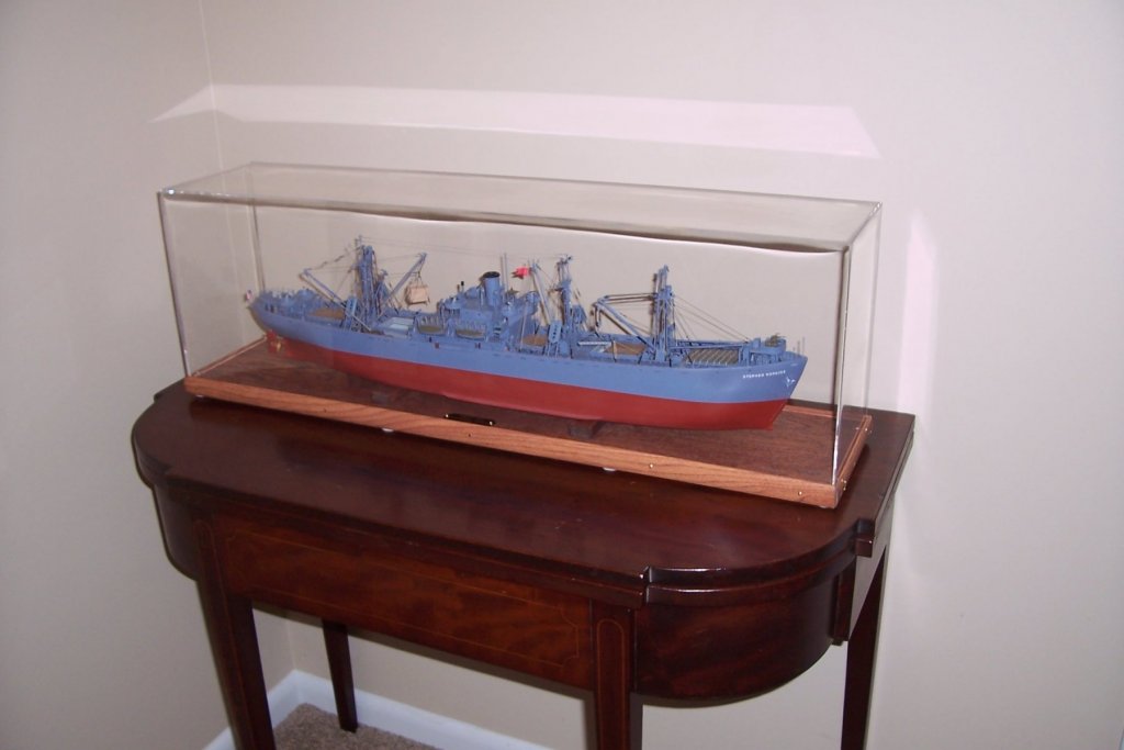
Well, she's done. Thank you to all who have followed along, made suggestions and contributed ideas. Hopefully I'll be back soon with a lobster boat build that I don't think has appeared here before.


- 227 replies
-
- 28
-
-
- BlueJacket Shipcrafters
- Stephen Hopkins
- (and 2 more)
-
Thanks Steve,but this can't hold a light to your Vance build. It amazes me that while they share the same hull the addition of all that superstructure makes the Vance look at least twice as big as a standard Liberty
- 227 replies
-
- 2
-
-
- BlueJacket Shipcrafters
- Stephen Hopkins
- (and 2 more)
-
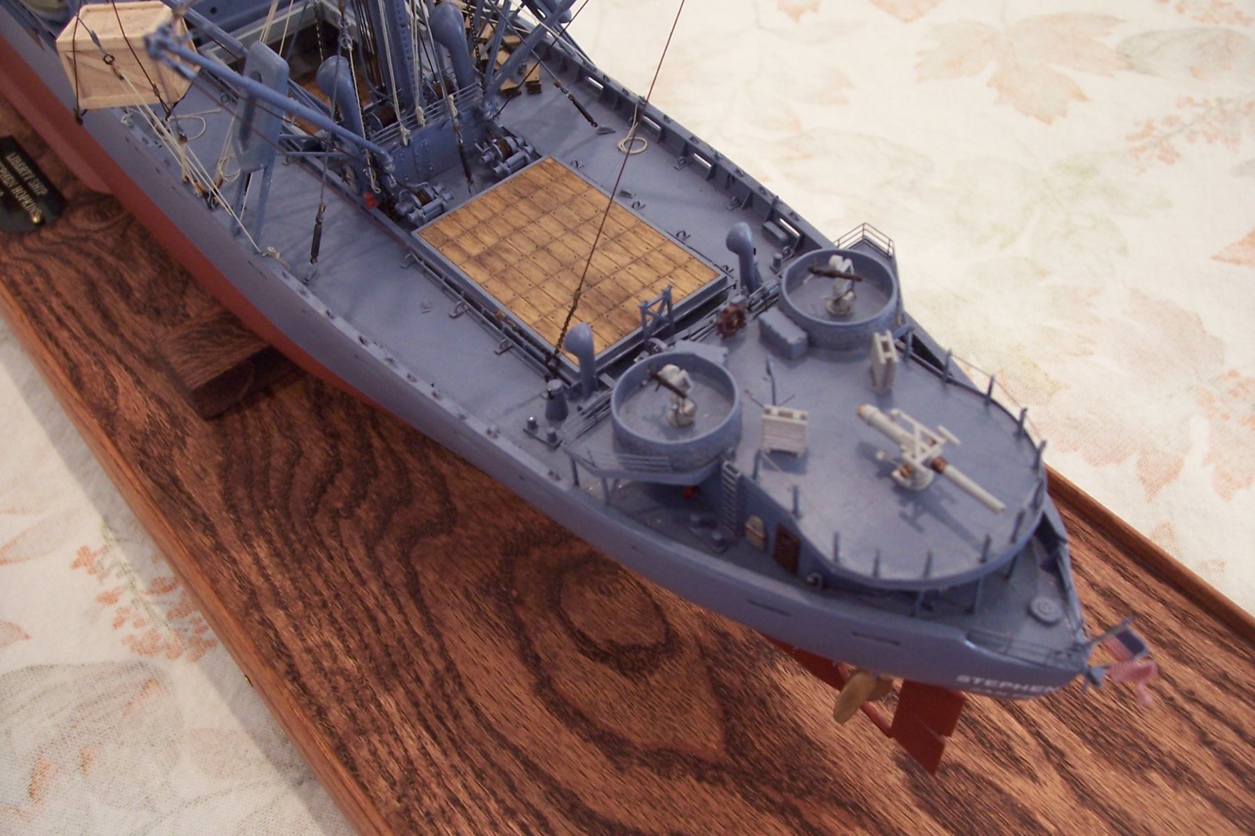
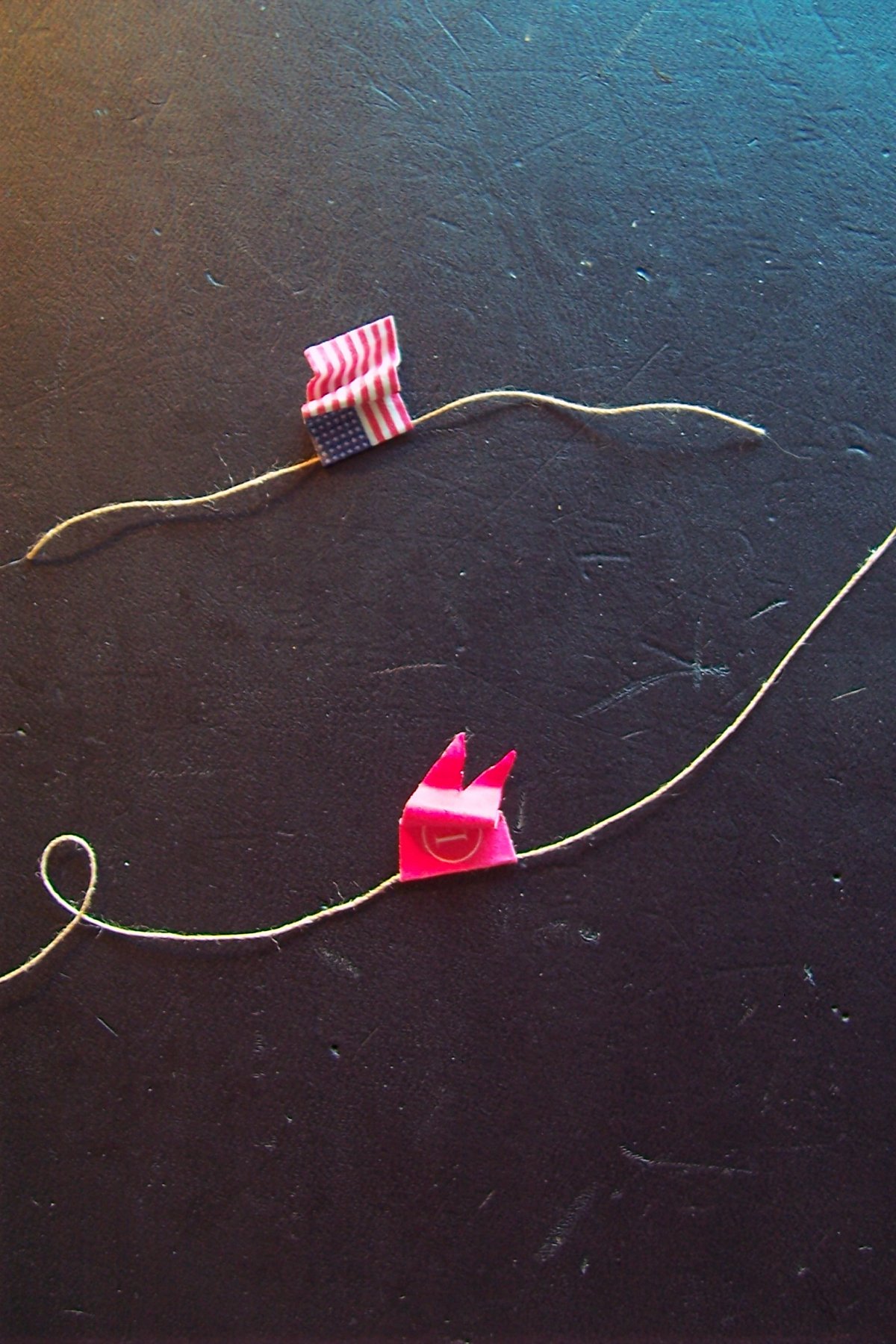
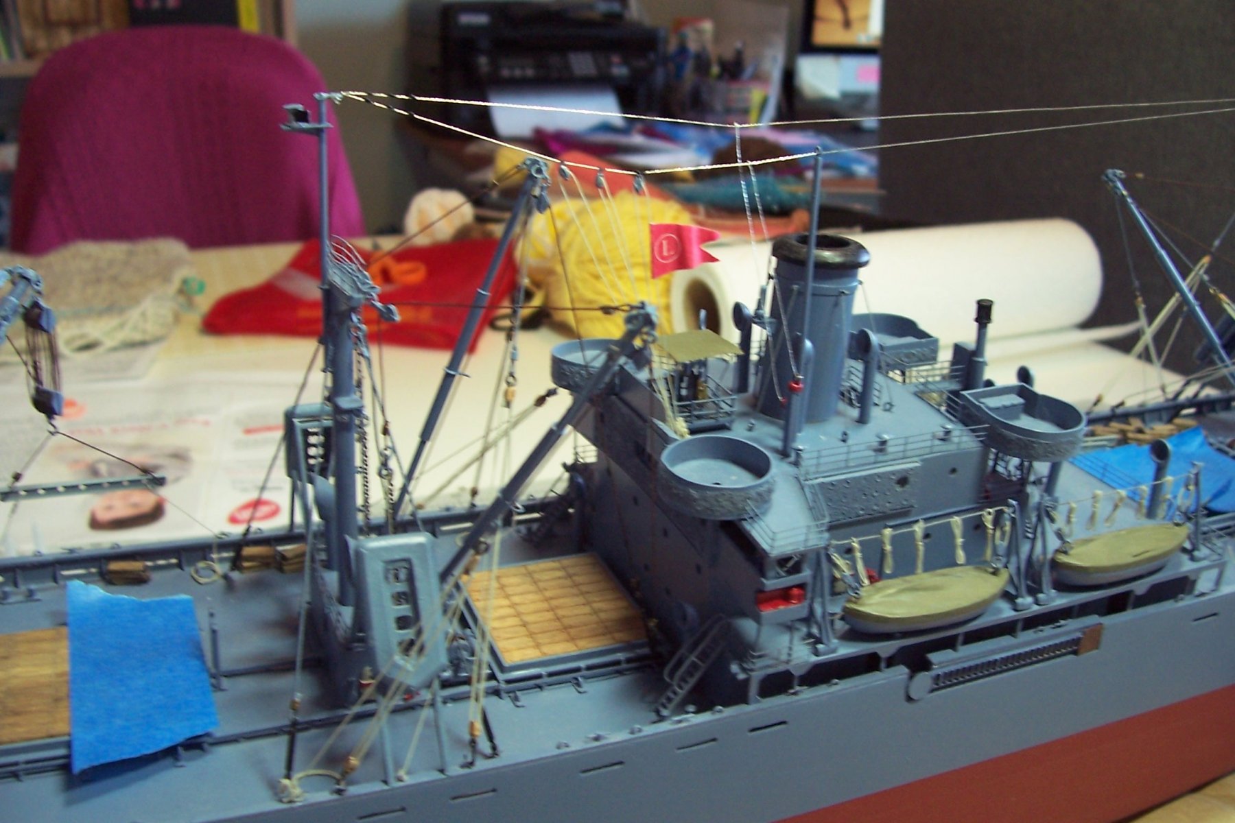
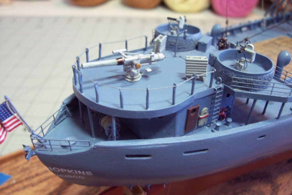
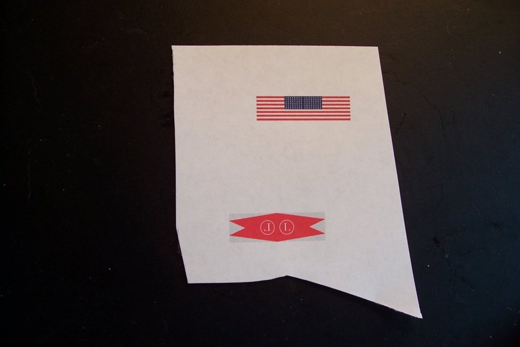
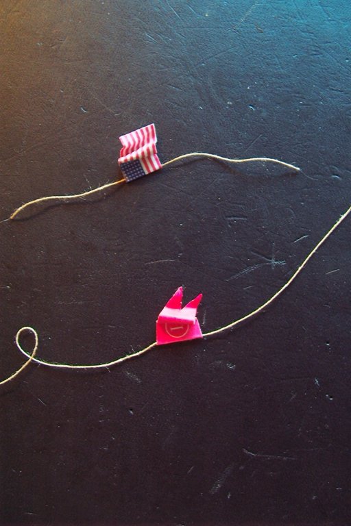
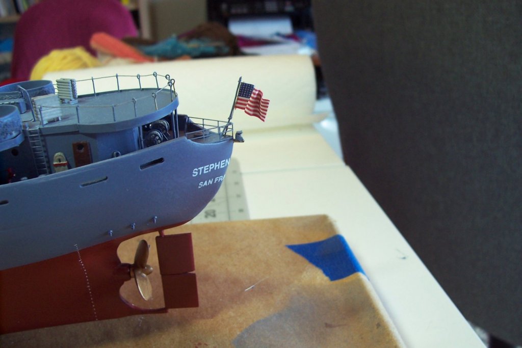
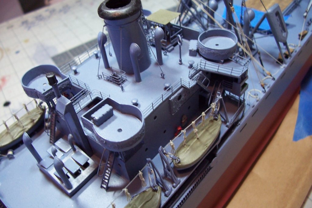
Radio Antennas and Flags I found a 48-star flag and the house flag for the Luckenbach Steamship Co online and copied them to my graphics program, adjusted their size, copied them and flipped one copy, backed each half together and printed them out. In order to get the paper to hold furls I used a trick I found on some modeling site. I cut a piece of aluminum foil slightly smaller than one half of the flag. I glued it in place using rubber cement because white glue has too much water in it and it will make the printer ink run. I then placed a length of halyard rope along the fold point, folded the flags and glued them together, once again using rubber cement. The furls were made by folding the paper around a pin, alternating directions. The antennas are made from some metallic thread provided in the kit, it simulates bare wire nicely. Both antennas run between the main and mizzen masts and are connected to the coupler tower on the flying bridge. The insulators near the ends of the antennas are just small blobs of white glue built up over several repetitions. The last thing left to add is the guns and then the big job comes - cleaning and dusting the model prior to casing it.


- 227 replies
-
- 14
-
-
- BlueJacket Shipcrafters
- Stephen Hopkins
- (and 2 more)
-
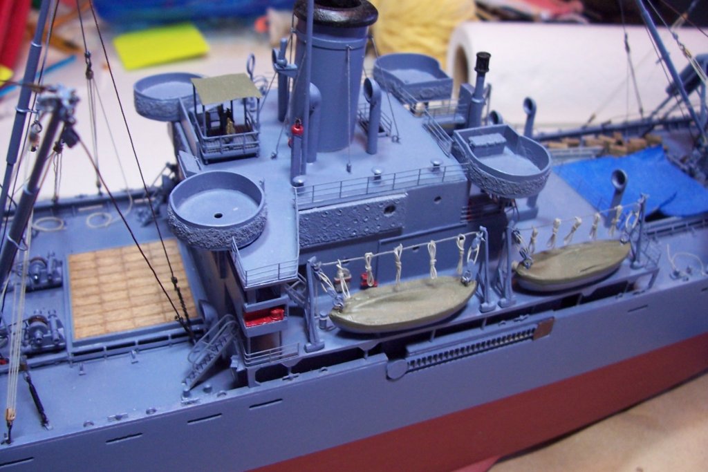
Lifelines and PE Railings The kit supplied PE railings were too thick for me so I used some 1/192 railings from Tom’s Modelworks which I find very easy to work with. The lifeline around the fantail gun platform is brass and thread. Next up will be the radio antennas and flags.
- 227 replies
-
- 10
-
-
- BlueJacket Shipcrafters
- Stephen Hopkins
- (and 2 more)