schooner
-
Posts
741 -
Joined
-
Last visited
Content Type
Profiles
Forums
Gallery
Events
Everything posted by schooner
-
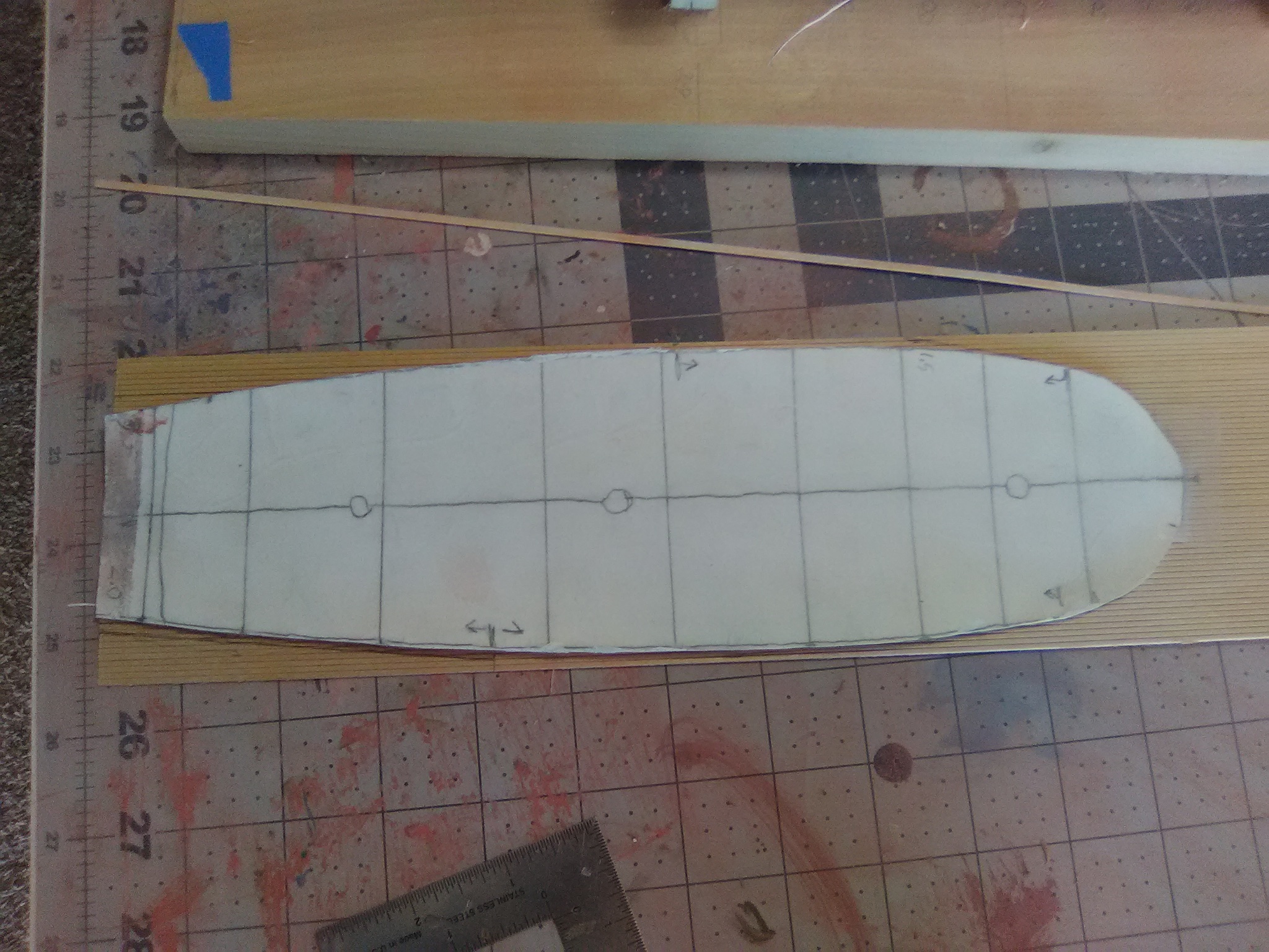
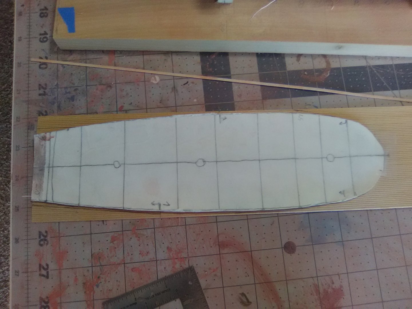
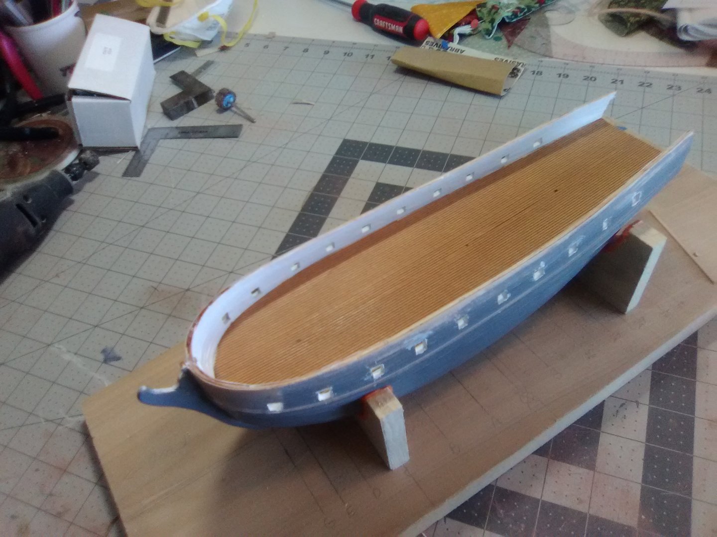
 Gun Deck Planking The ceiling planks are finished up and painted: The instructions call for measuring the deck with dividers and using the measurements to lay out a template for cutting out the pre-scribed deck planking but I thought it would be easier to trace the gun deck from the plans, leave some extra around all sides and then test fit and trim as necessary: The template worked well but given the tumblehome on the bulwarks I could not drop the sheet onto the deck - I had to cut it in half down the centerline. After a lot of test fitting and trimming of each half I ended up with a good fit - any minor gaps along the side will be covered by the water ways. Before I installed the deck I stained it with Old Master Fruitwood Gel Stain which Chuck Passaro is using on his HMS Winchelsea group build here on the site. It’s great stuff! Although the planking is bass wood there was no blotching, it went on easily. It’s initial color was a light, almost yellowish tan but after a couple of hours it darkened to more of an oak color and the plank seams are readily visible so I did not have to try to darken them with a pencil, which I’m sure would not have gone all that well. I glued the plank sheets down with 2-part epoxy to give me enough time for final adjustments before it set and, most importantly, to avoid any swelling of the wood which can come from the water in wood glues. Next up will be adding details to the gun deck.
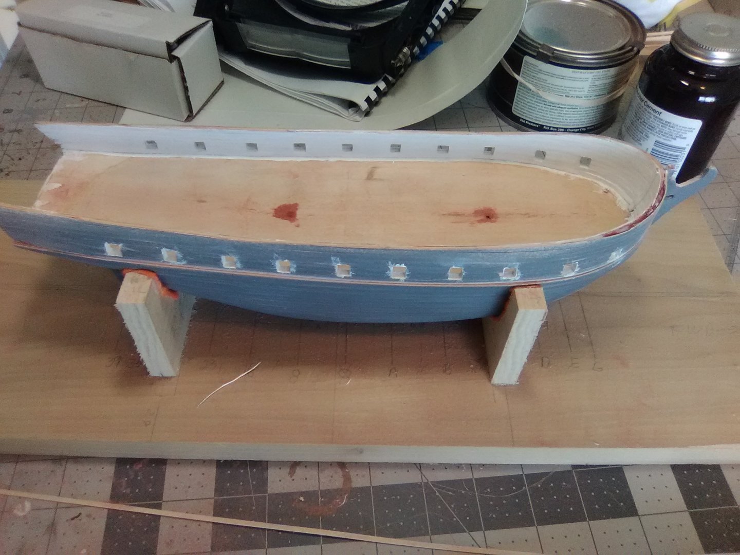

- 142 replies
-
- 5
-

-
- alfred
- solid hull
- (and 2 more)
-
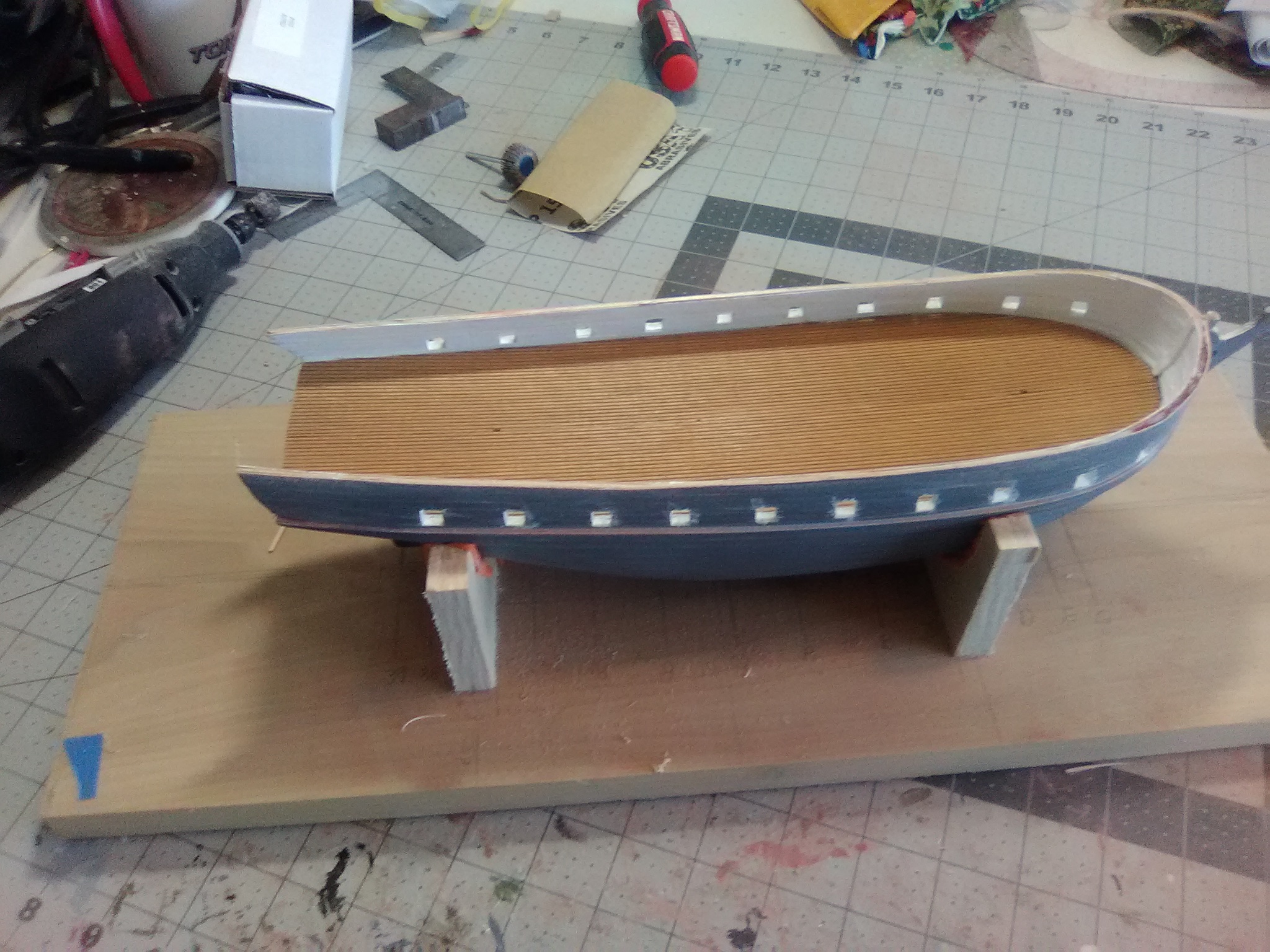
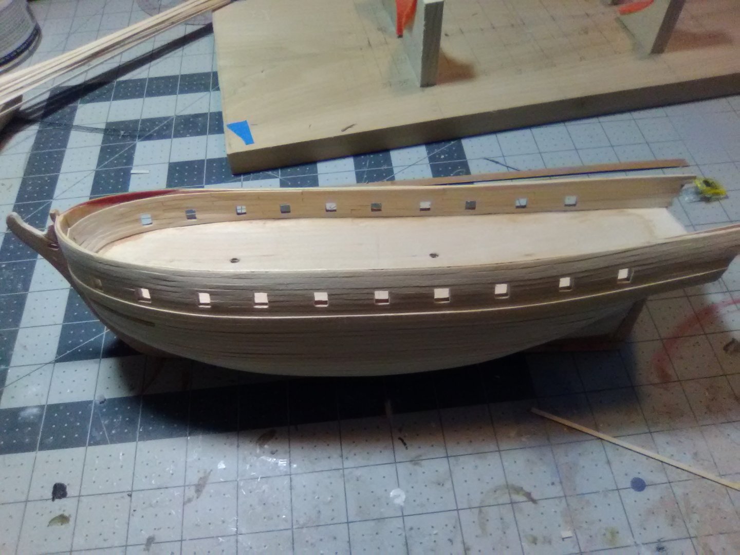
Ceiling Planks After reopening the gunport the ceiling planks went in pretty easily along the inside of the bulwarks. I’ve got a few more to go up forward and then it will be time to break out the filling putty, sandpaper and primer.
- 142 replies
-
- 4
-
-
- alfred
- solid hull
- (and 2 more)
-
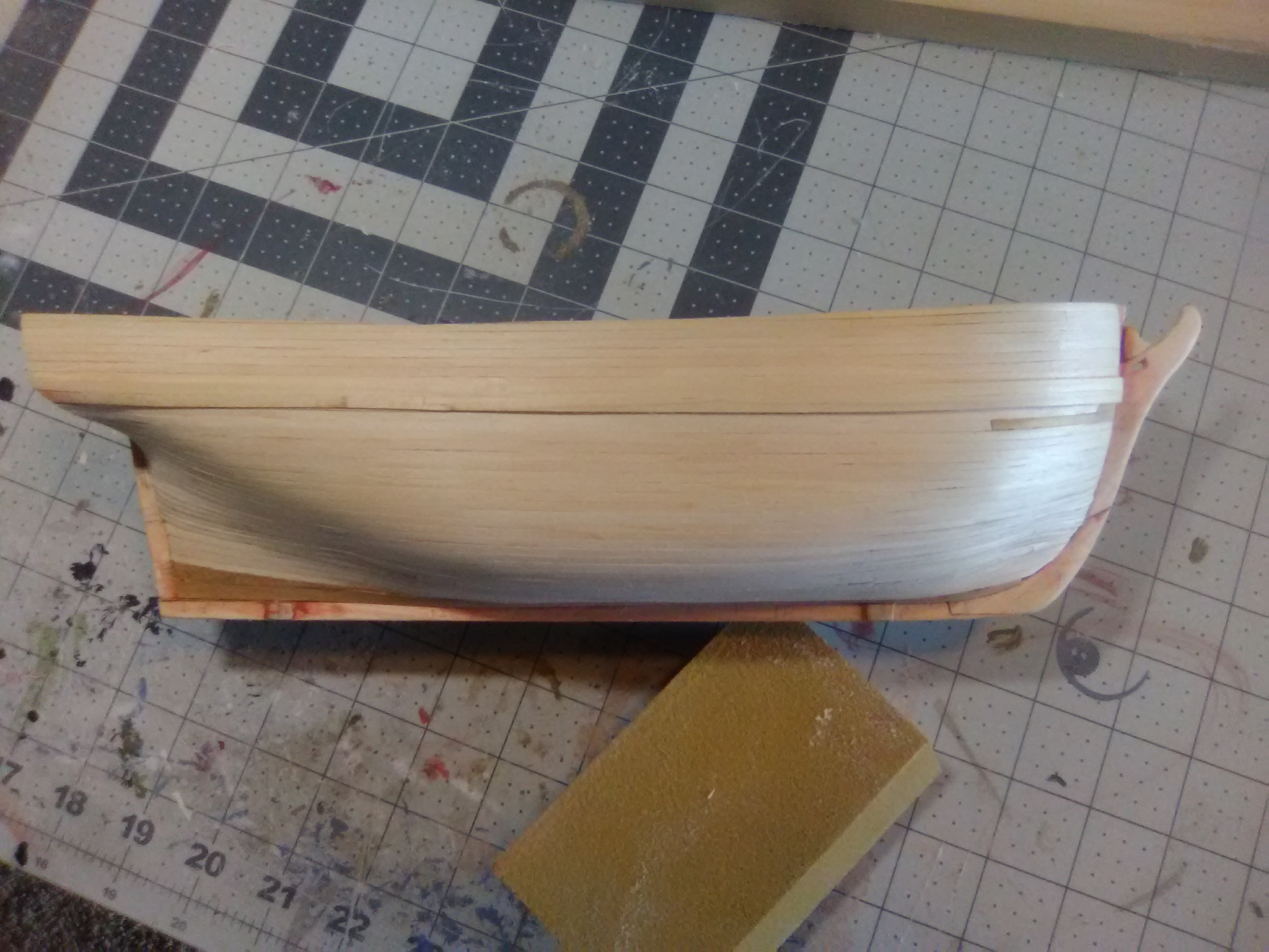
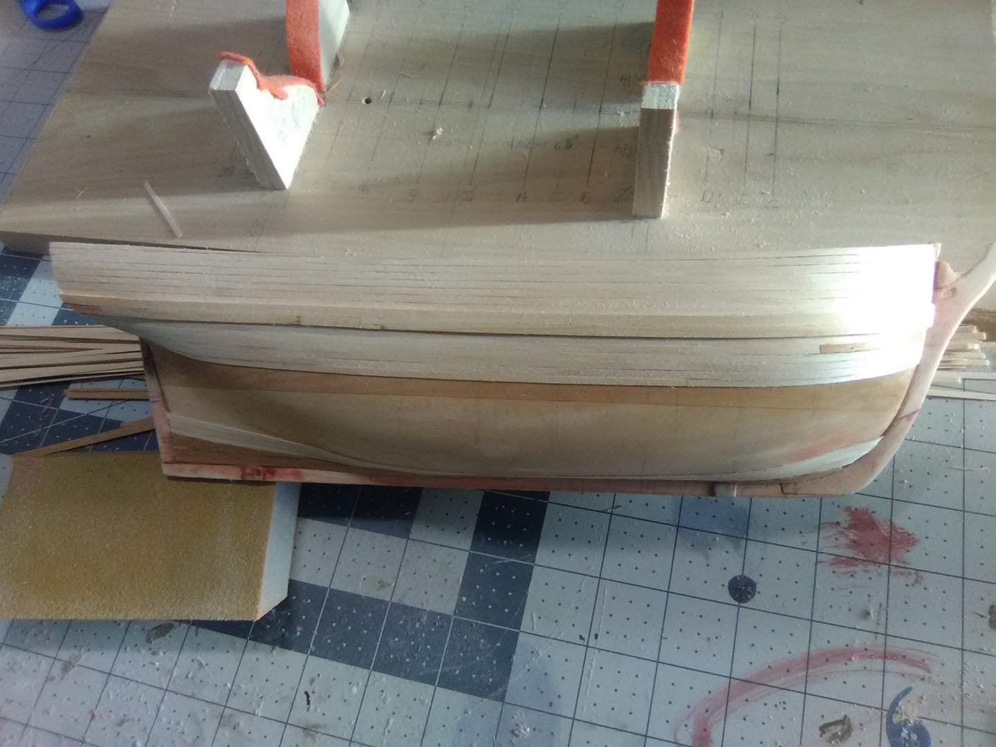
Exterior hull planking done You can get away without planking this hull at all but I thought it would be good practice for me since I have the MS kit of the SYREN on the shelf and that kit calls for some good planking skills. While this kit is not a good choice for someone’s first build I do think it would be a good choice for a first planking job for the following reasons: The hull will be completely painted so after priming and several coats of paint pretty much all of the plank seams and butts will be invisible - so will any learner’s mistakes - like mine Planking a solid hull is easier than a POB hull since you have plenty of glueing surface, don’t have to worry about fairing the bulkheads and you can terminate a plank anywhere you want The small size of the hull and the long lengths of supplied planking strips mean that you don’t have to cut most of the planks - they can run end to end The supplied planking is 2mm wide and .02” thick so it is very pliable, which allows you to get away with easy edge bending, no soaking or heating to bend it and no spilling to avoid twisting. One drawback to it is that it allows you to get away with things that thicker planks would not so the planking “experience” you get from this kit is not all that it could be. That said I was able to add some drop planks, stealers and practice tapering. Next on my to do list is to reopen the gun ports and then plank the interior of the bulwarks (ceiling)
- 142 replies
-
- 5
-
-
- alfred
- solid hull
- (and 2 more)
-
Nice looking boat! I thought it might be a Grand Banks. There is an interesting build log of Amati's Grand Banks kit, "Grand Banks by Mindi" https://modelshipworld.com/topic/24208-grand-banks-46-by-mindi-amati-models-120/ I've been thinking of doing an RC build but I don't want to mess around laying fiberglass on a wood hull. This kit has a fiberglass hull but some very nice looking wood detailing inside and out. You could probably bash it into a good facsimile of your boat.
- 87 replies
-
- 1
-
-
- bluejacket shipcrafters
- red baron
- (and 3 more)
-
James, I'm not sure what primer you are using but I've always had good luck using Krylon spray primer (grey or white) from the hardware store. It goes on pretty evenly, dries quick, sands well and forms a good base for the paint.
- 32 replies
-
- 1
-
-
- red baron
- first build
- (and 1 more)
-
Your right, sorry. BTW, is your "avatar" photo your boat?
- 87 replies
-
- 1
-
-
- bluejacket shipcrafters
- red baron
- (and 3 more)
-
James, I'm not sure what primer you are using but I've always had good luck using Krylon spray primer (grey or white) from the hardware store. It goes on pretty evenly, dries quick, sands well and forms a good base for the paint.
- 87 replies
-
- 1
-
-
- bluejacket shipcrafters
- red baron
- (and 3 more)
-
I don't think you will have a problem with it sticking to the bondo but there is a real "gotcha" to watch out for - something I learned the hard way with scribed decking. Wood glue like Tite-bond or white glue like Elmers has a lot of water in it and it can cause thin decking material to swell, buckle or warp. If you have enough decking material that you can spare some you might want to experiment a little - get a piece of wood (same type as the hull if possible), put some bondo on part of it (just to see if that will be a problem), sand it smooth and then pencil in an area on the top of it (not all the way out to the edges), cut a piece of decking the same size as the shape you drew , put on as much Tite-bond as you normally would (leaving a few spots bare to see if warping occurs, glue it on and see what you get when it is dry. You could go with slow (i.e thick) CA but that has it's own problems - you get very little time (if any) to move the decking around if you don't place it just right the first time. This may seem like overkill but on your Atlantic the deck will have a huge visual impact so you want to get it right.
-
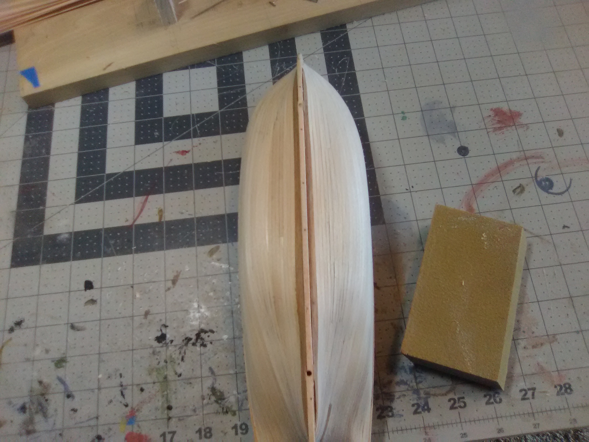
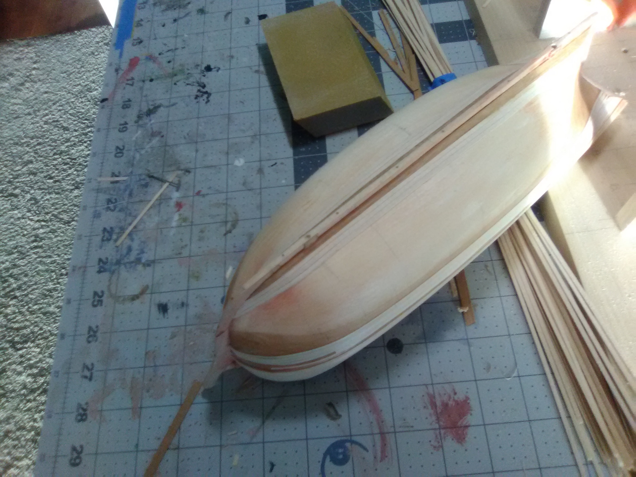
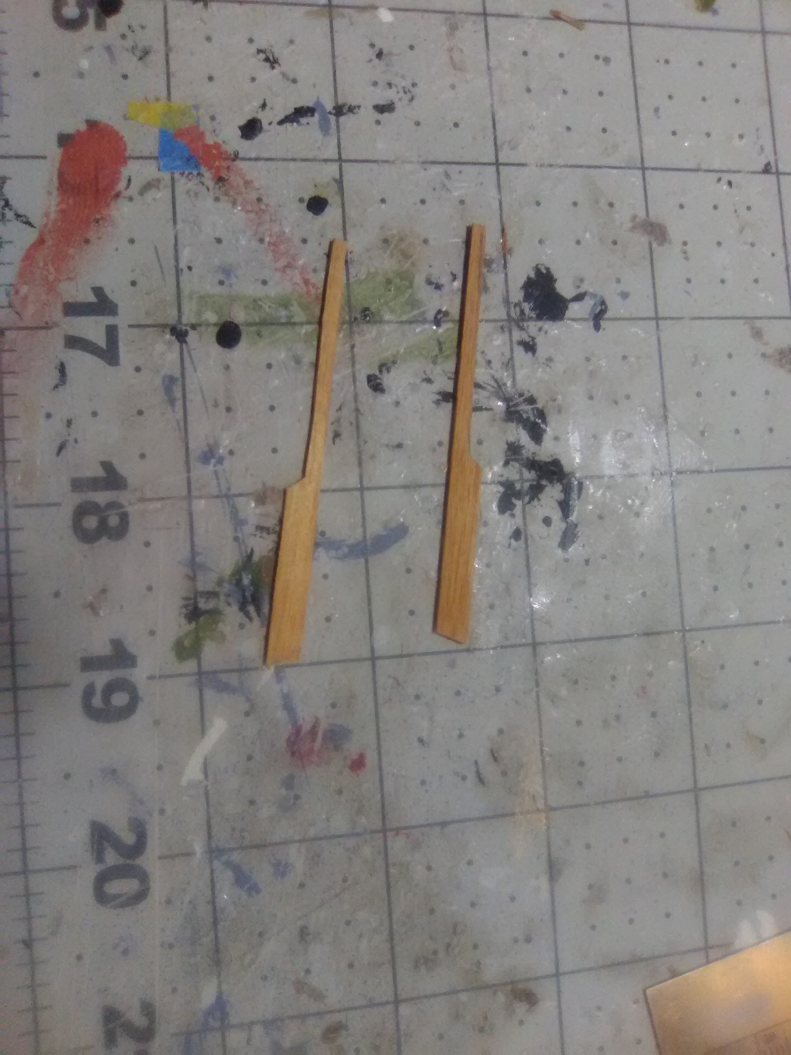
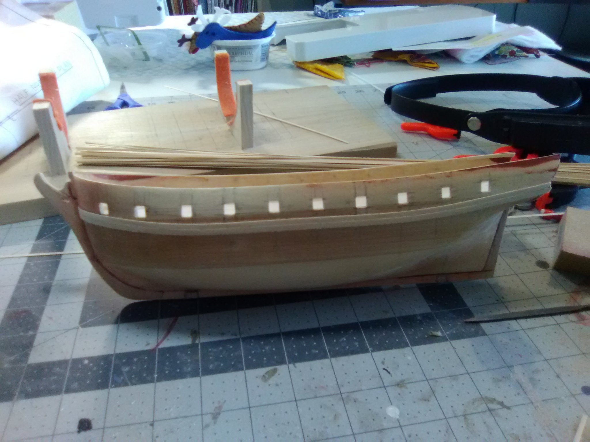
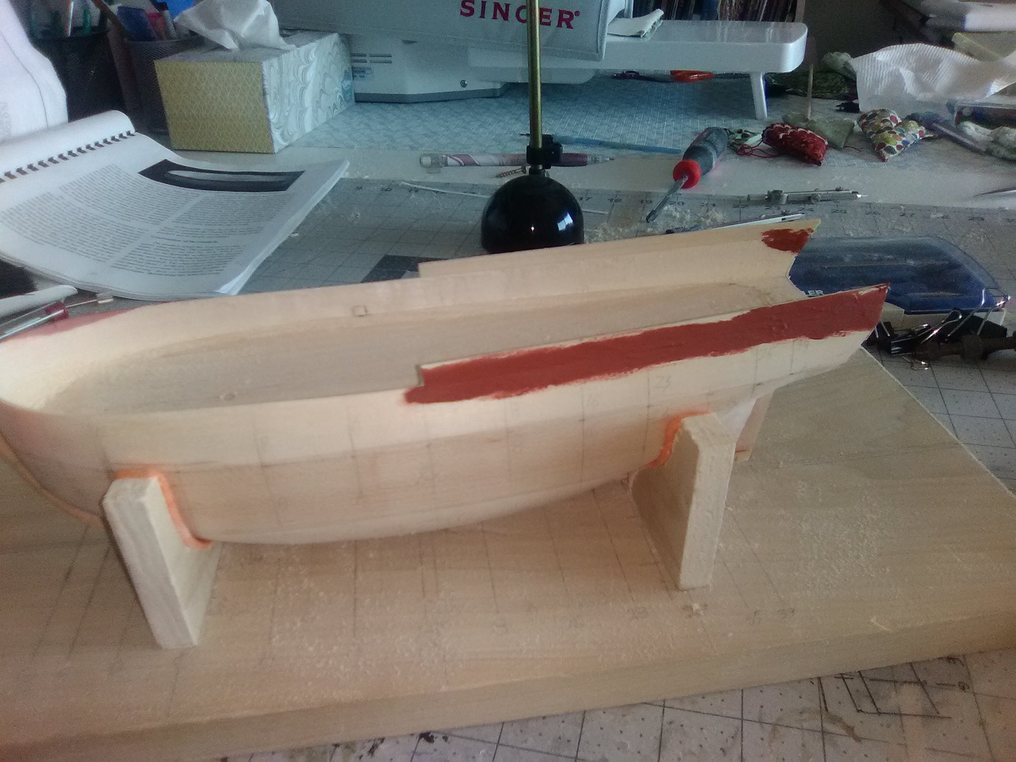
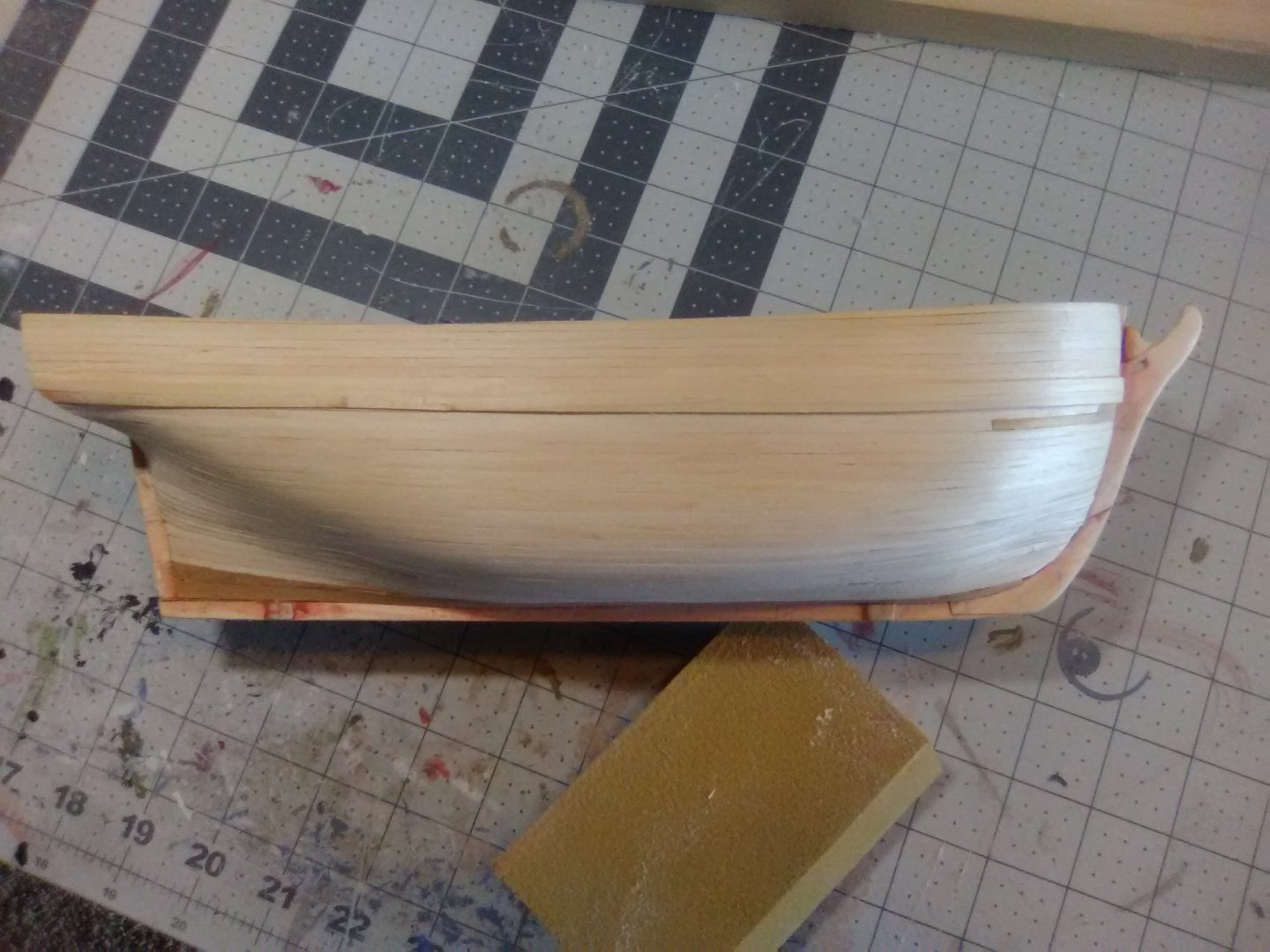
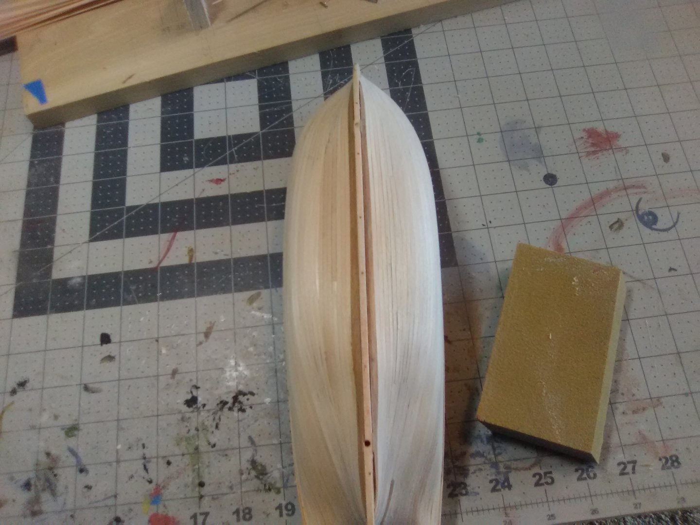
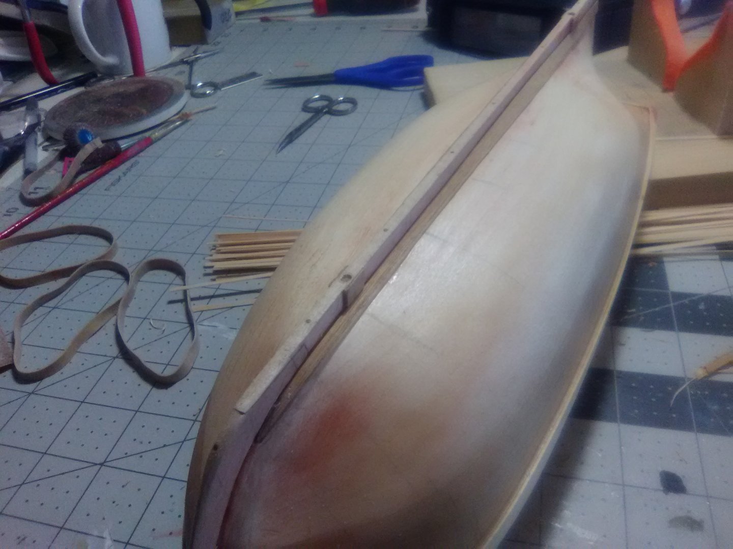
More Hull Planking Planking is coming along better than I thought it would since this is only my 2nd planking job and the last one was about 15 years ago. The instructions call for making the Garboard planks from a template but that implies having some thing to copy, which there is not. I found some mahogany strips in my stash that are wider than the kit planks and just a little thicker so they will be noticeable even though they will be painted. I read up on various build logs an shaped them as best as possible. I noticed on Chuck Passaro’s group build for the Winchelsea that ships of this period frequently had a drop plank at the head of both strakes below the wales so I made a couple out of the same strip material as the garboards, fitted them and then sanded them down so they are the same thickness as the rest of the planking. I expected to have to taper the planks near the bow and add stealers near the stern but this hull shape is a little surprising. I’m going to have to taper both the bow and stern areas - I guess it is because being built as a merchant ship the ALFRED has a much deeper and broader “belly” since cargo capacity was more important than speed like it would be for a frigate.


- 142 replies
-
- 6
-
-
- alfred
- solid hull
- (and 2 more)
-
Gahm, Wonderful work! I've got the Syren on the shelf and am noting those build logs worth emulating and yours is sure one of them! Question about the carronades - are they kit-supplied or after market from BlueJacket or Caldercraft ? The ones in my kit are way too skinny. Thanks and keep up the good work!
-
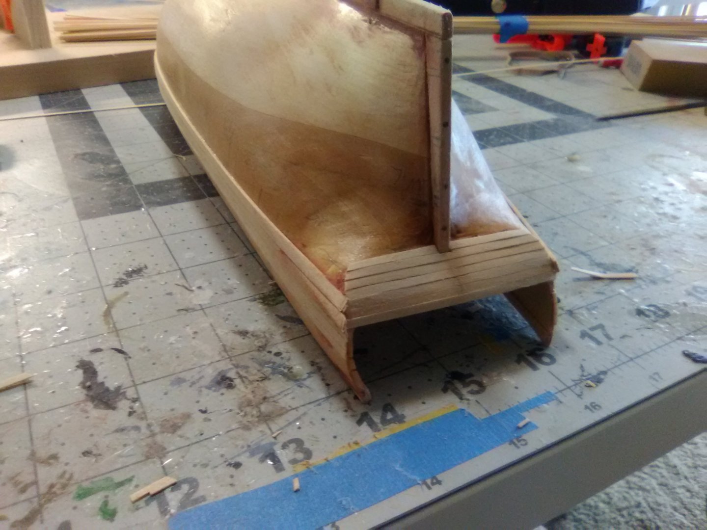
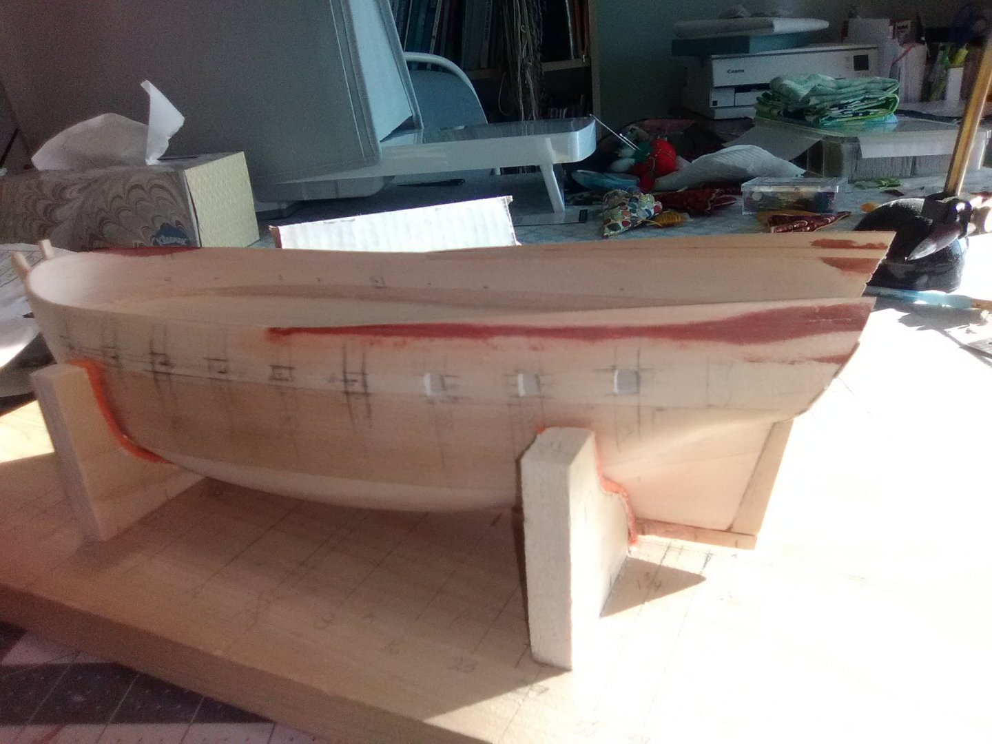
Bulwark planking The planking from the wales up to the top of the bulwarks is completed. This section was very easy to plank and without the need to figure out butt locations each strake went on as a single plank. Since I will be handling the hull a lot while planking the rest it I decided to hold off on reopening the gun ports - less chance of getting a plank end snagged on my clothes. Next up I’m going to try to make a template for the garboard strake and then put those in place.


- 142 replies
-
- 5
-
-
- alfred
- solid hull
- (and 2 more)
-
Hi Thunder, The box says she was built in 1777 but I think they got they wrong by a century. There was a frigate Alliance built in 1777 but she doesn't look anything like this. The second Alliance was built in 1877 as a gunboat and is a very close match for you kit, including the smokestack, and as the kit box says she spent quite a few years as a training ship You can Google USS Alliance and see photos or drawings of both ships. I have never heard of Pyro before but it looks like an interesting build. Good luck with her. By the way, the photos of your completed builds are very impressive - wish I could plank like that!
-
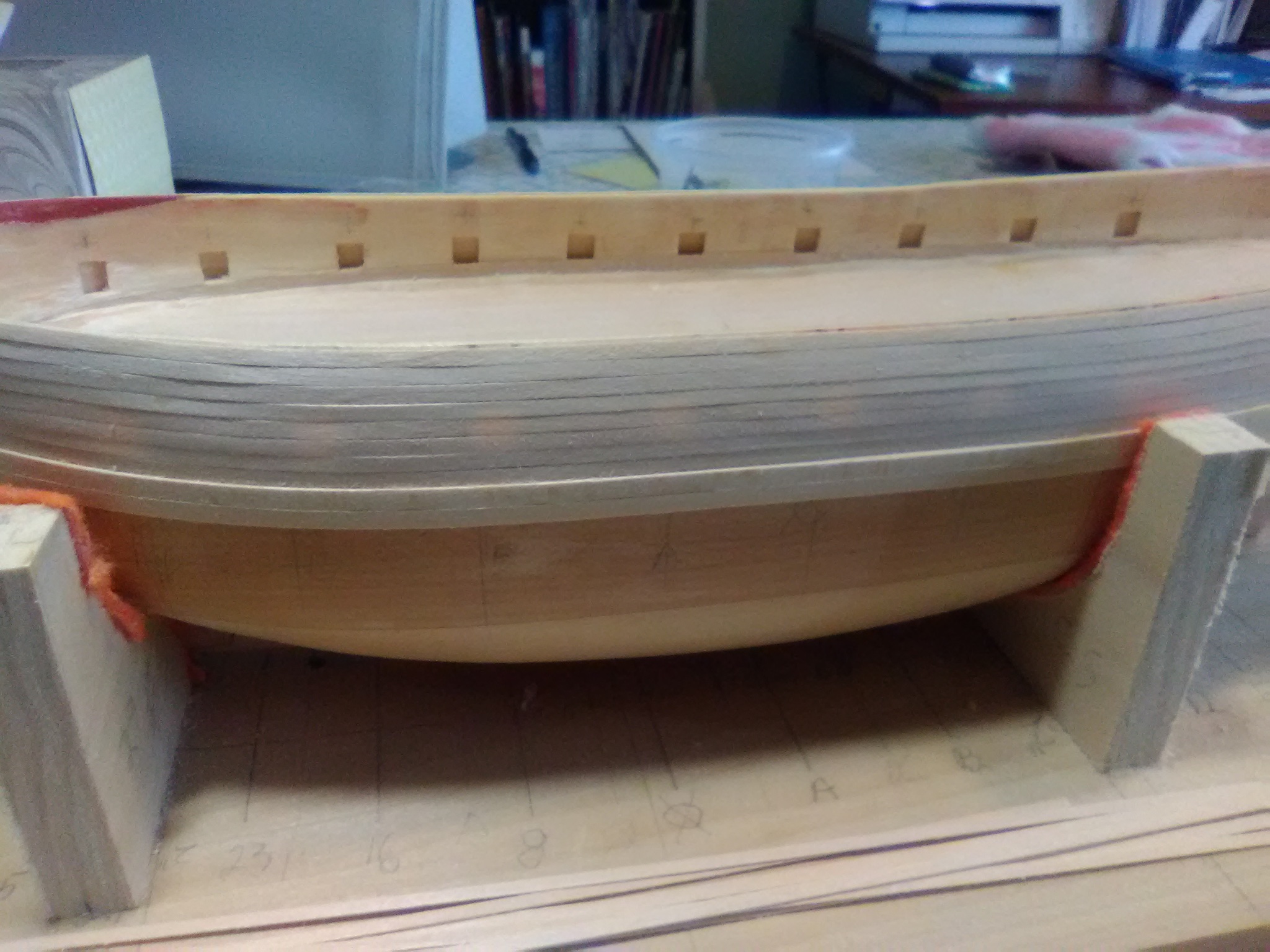
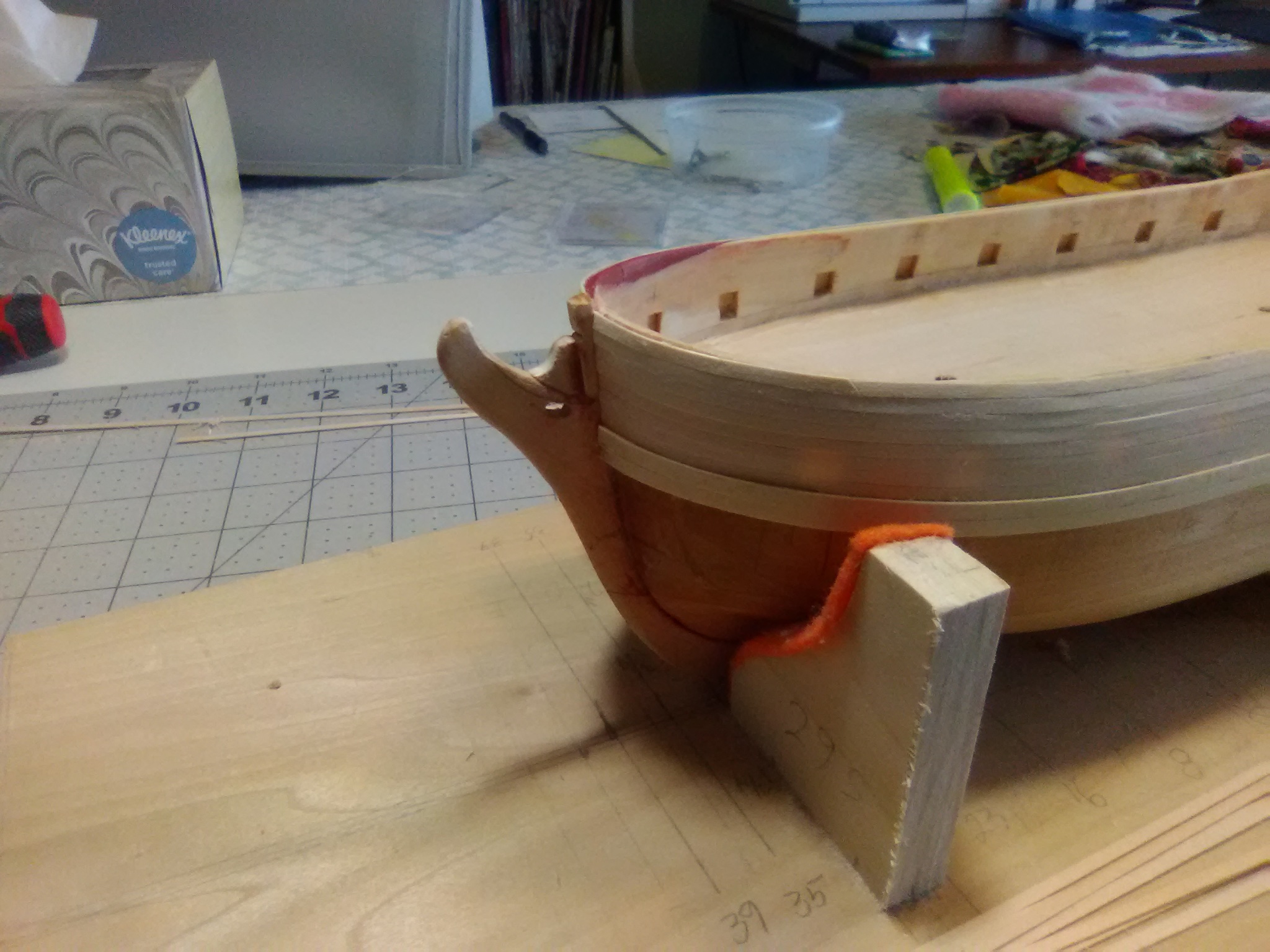
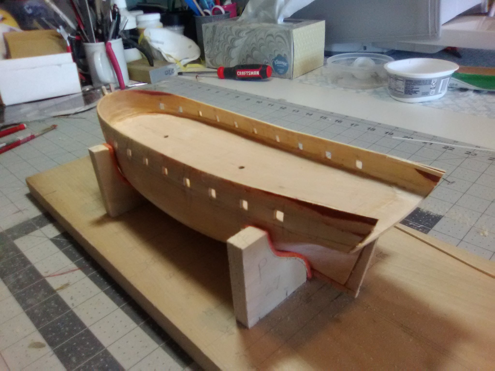
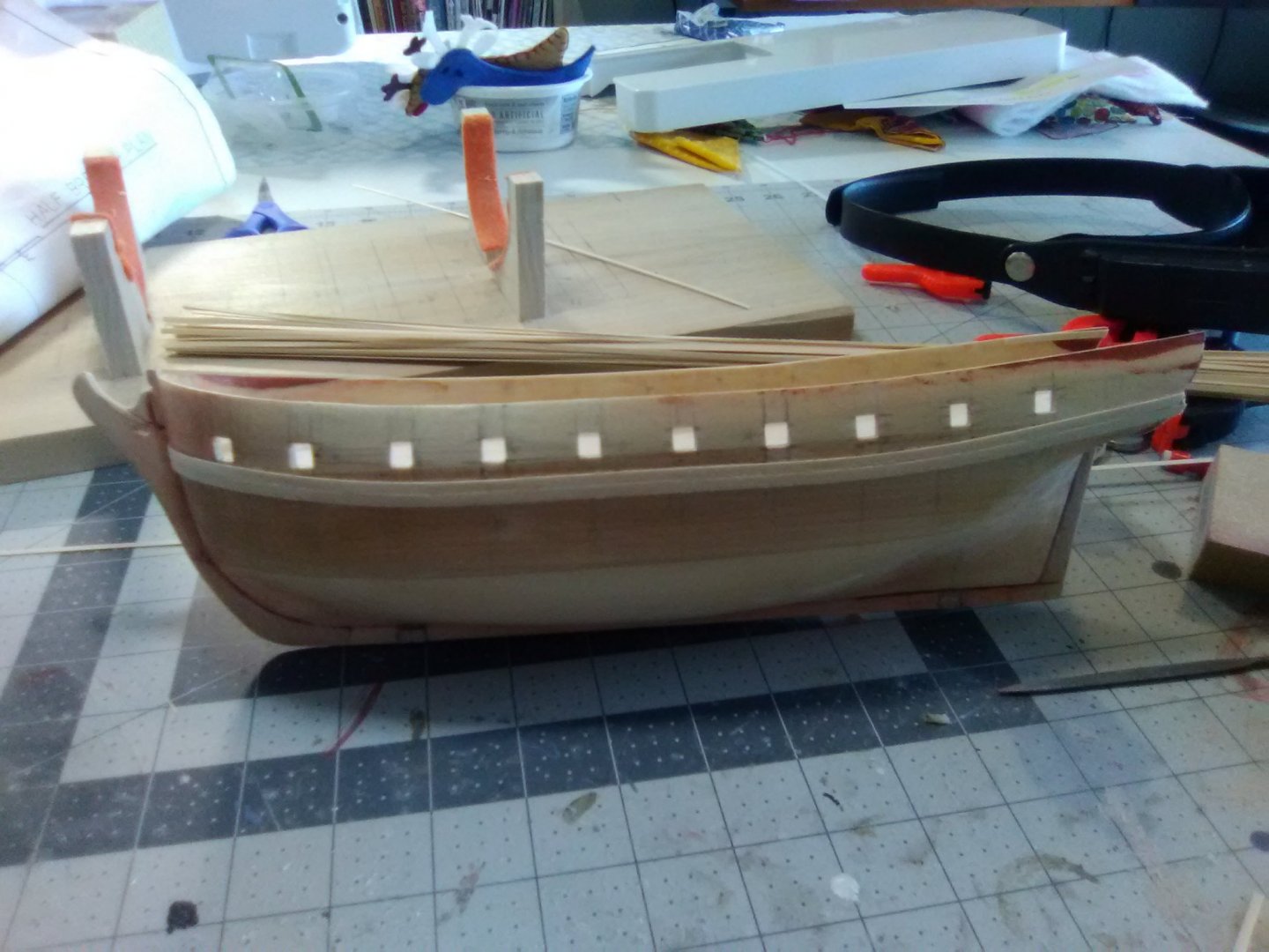
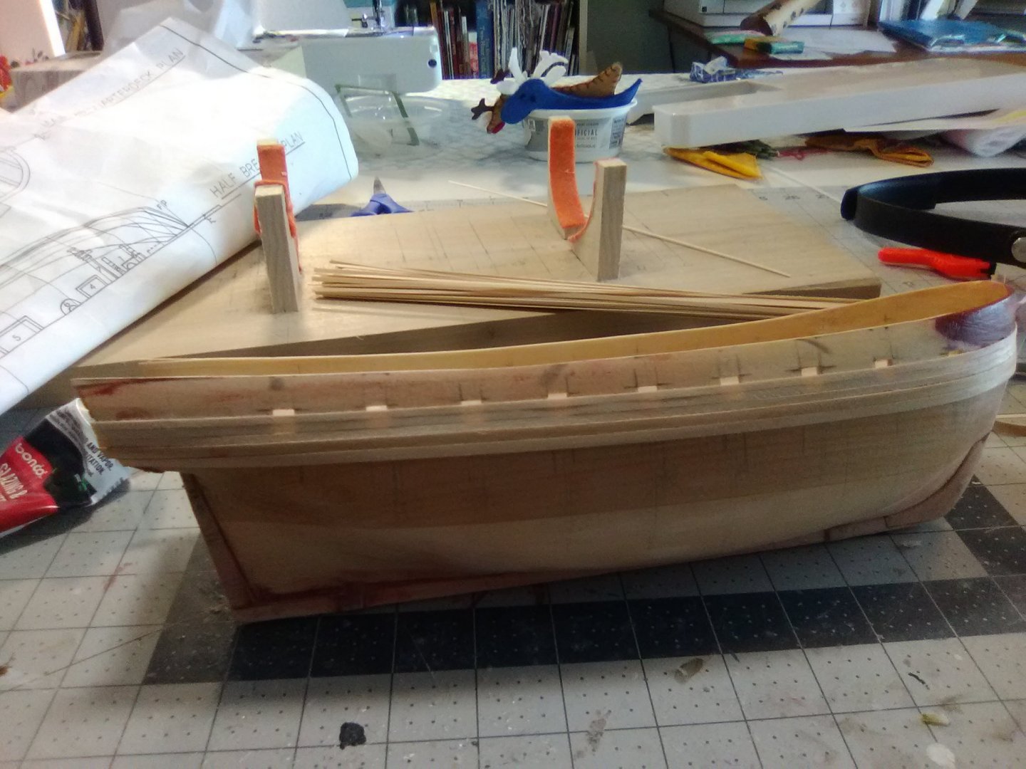
Start of hull planking The first thing I put on were the wales. The instructions call for 2 strakes but per the plans the wales are 1/4 inch high and the material provided is 1/4 inch so at some point the wood strip provided must have changed from 1/8” to 1/4”. I checked my spare parts bin and found some 1/8” of the right thickness and I went with that since it is much easier to edge-bend 1/8 than 1/4. As it worked out, I did not need to heat or soak the wale strips to get them around the bow. Next up I did the counter earlier than the instructions call for because I think it will be easier to get a neat intersection between the hull and counter planking this way. I’ve started to plank the outer bulwarks, following the instruction’s suggestion to just plank over the gun ports in order to keep the planking seams aligned. I’ll cut out the ports again when I’m done (and do it a 3rd time after planking the inside of the bulwarks.)
- 142 replies
-
- 4
-
-
- alfred
- solid hull
- (and 2 more)
-
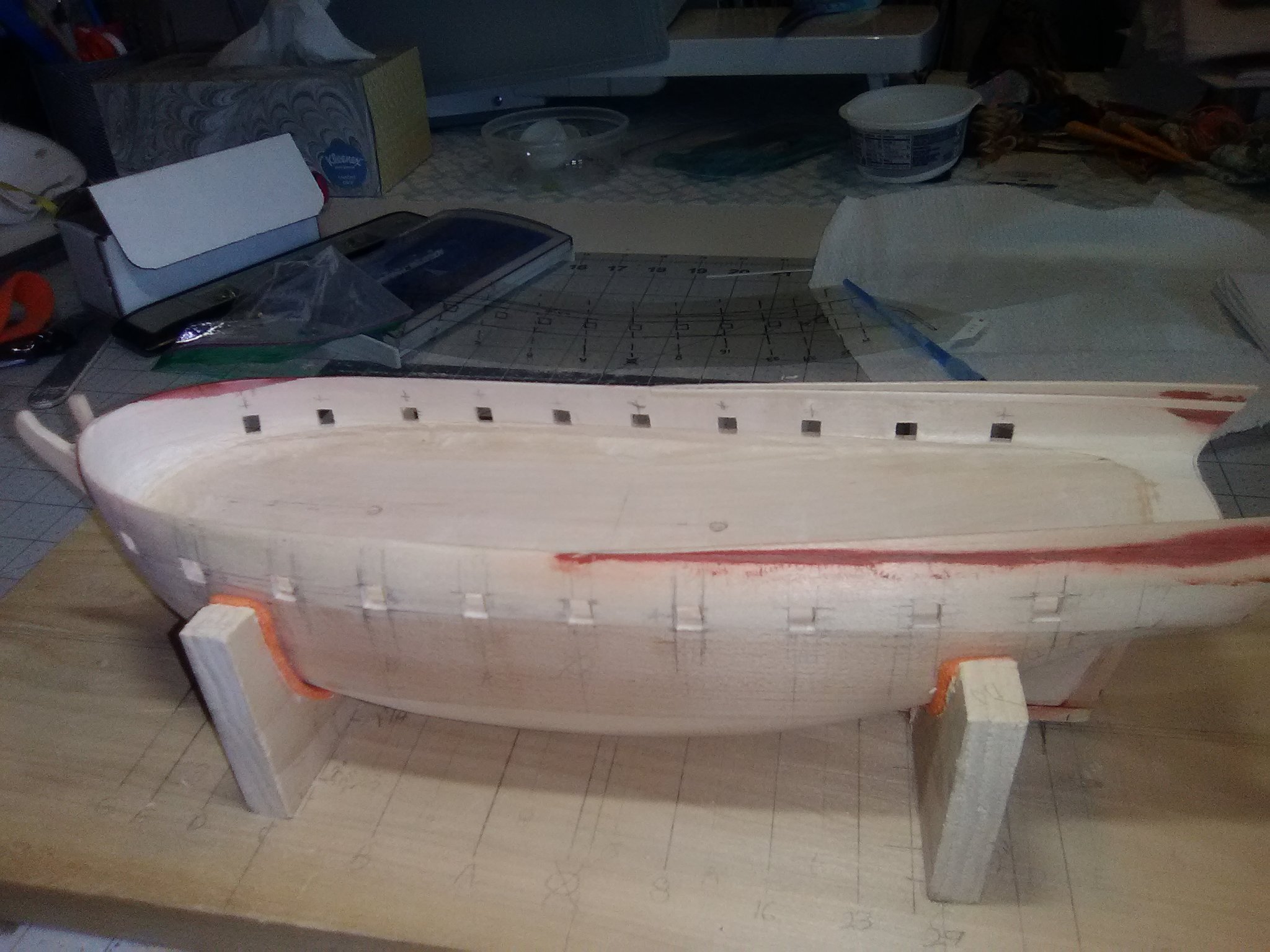
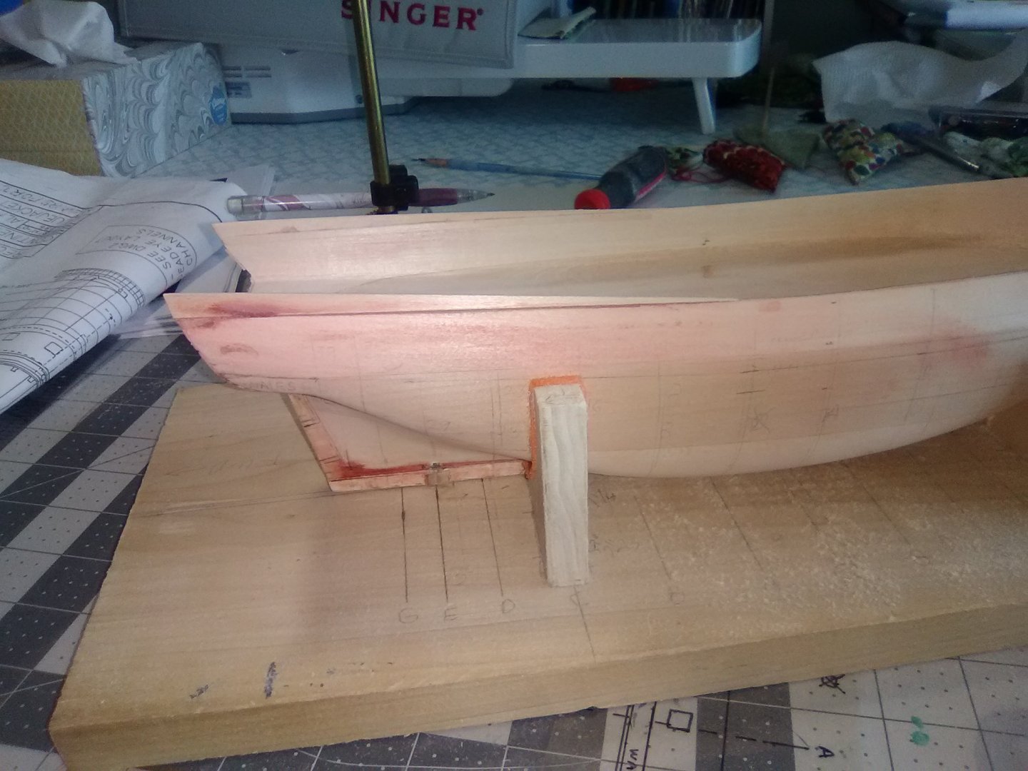
Planking preps There were a couple of things I needed to take care of before starting the planking. I deepened the rabbets on the stem and sternpost so they will hold the plank ends. Using the gun ports as references I marked the location for the top of the wales and the height of the bulwarks to match the plans. For the hull I received, the bow area was right on, the waist needed to come down a little, 1/4” or less, and the aft most 2” needed to come up just a little - something I had already added and then ended up removing most of it. The final item was something I have not done before. The instructions call for coating the hull with thin CA glue and then lightly sanding it to give a smooth surface for the planking that will also resist soaking up most of the planking glue. Since this is the first time I will try planking a solid hull it made sense to me so I did it. Next up will be attaching the wales and then planking the bulwarks.

- 142 replies
-
- 5
-
-
- alfred
- solid hull
- (and 2 more)
-
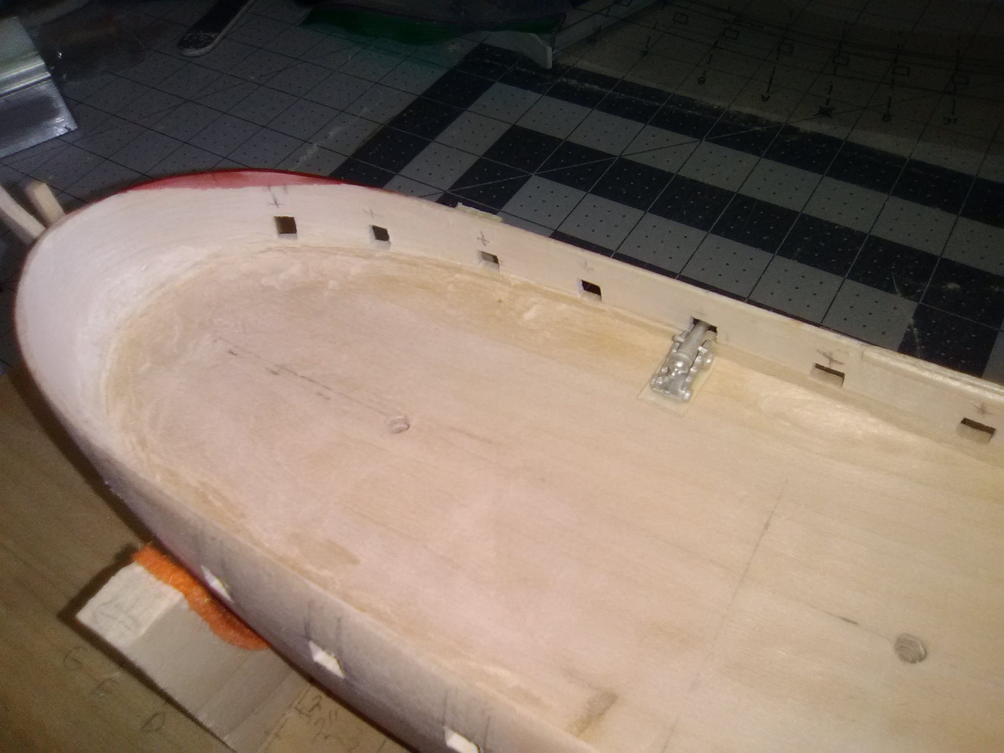
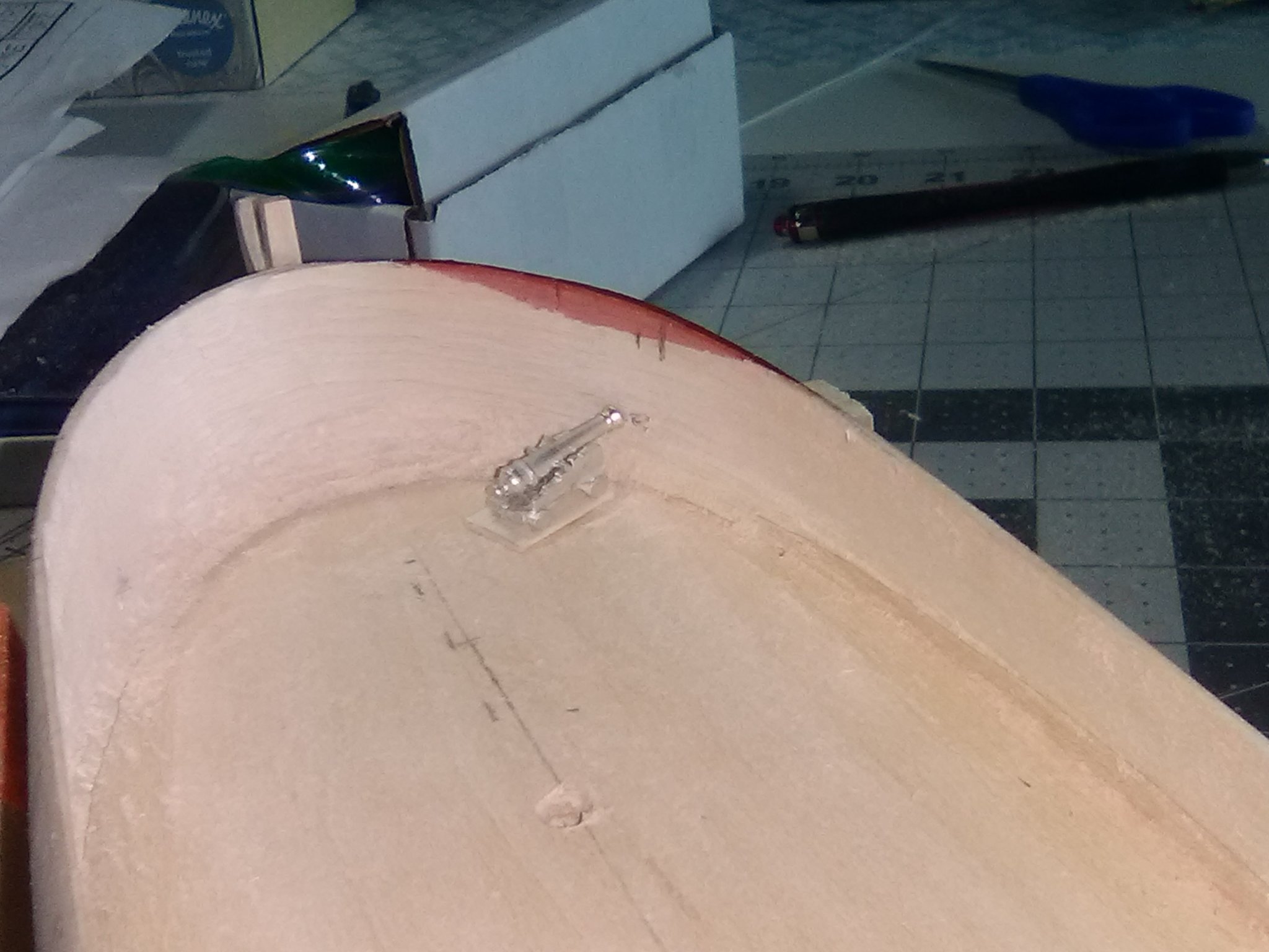
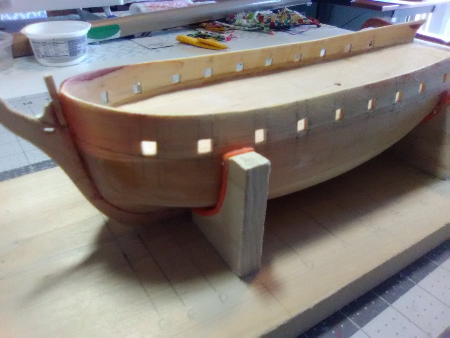
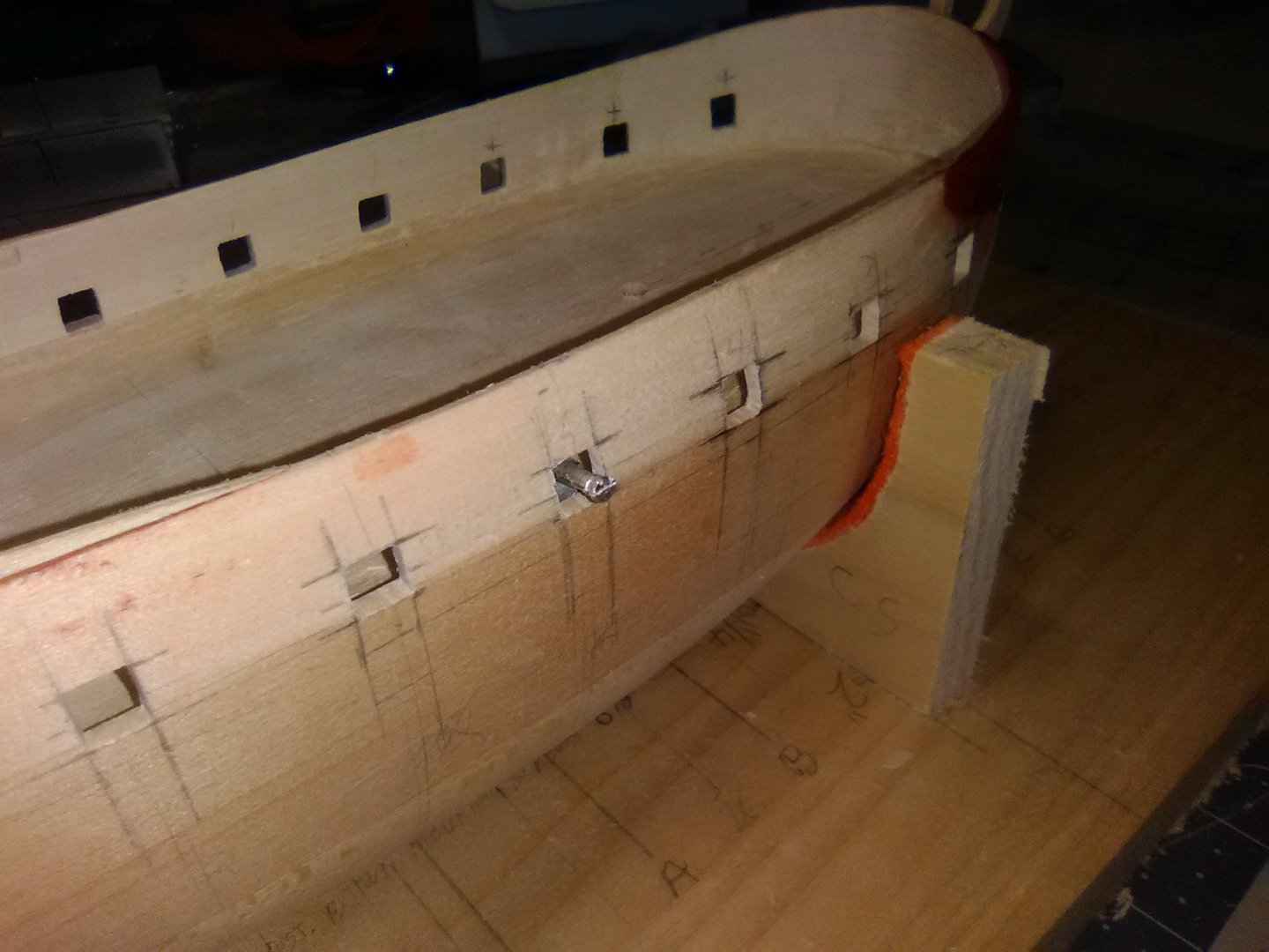
Finishing up the gun ports After filing 3 or 4 a day I finally finished all 20 gun ports. I used my test cannon to confirm that the gun barrels were centered in the ports, they were - almost. There was still a small “shelf” of wood right at the base of the ports (where the deck and the bulwark meet) that I could not see or even feel with my finger but when I pushed the cannon right up to the bulwark the barrel would rise on almost all the ports so I had to spend a fair amount of time using what amounts to a milling cutter on the Dremel slowly going over that area until the guns are all centered. The next steps will be getting the hull ready for planking.


- 142 replies
-
- 5
-
-
- alfred
- solid hull
- (and 2 more)
-
Glazing putty from an auto store will fix just about anything. If you need it to be thicker than about 1/16" then you need to put in on in several thin layers, allowing each to dry. A one-time thick application may not dry properly inside and will not harden.
-
One trick for filling small cracks is to use white (or Elmer's) glue. It has the strange property that if you are filling in a small crack or gap, say between a deck and a vertical bulkhead, the glue not only fills the gap but it tricks the eye into not even seeing the filled crack even though the glue dries transparent. That has really saved me a couple of times where I had 2 surfaces painted different colors that would have been tough to tape off and paint - white glue made the problem invisible1
- 32 replies
-
- 2
-
-
- red baron
- first build
- (and 1 more)
-
Laying out the gun ports I’ve been spending a LOT of time measuring, marking, comparing, erasing, remeasuring, etc, etc, etc as I’ve tried to figure out where the gun ports are supposed to go. It’s no surprise to anyone on this site that one of the great things about working with wood is that there are few unrecoverable errors but getting the gun ports wrong on a model of this size might be one of them so that is why I have been doing all the ruminating. In the process of figuring out where the gun ports go I also dry-fitted the PE transom and figured out I would need to raise the after part of the bulwarks a little so I added a 1/8” strip and then sanded it down to match the sheer of the quarterdeck. Later on I’ll probably have to take off most of what remains. The instruction call for laying out the gun ports using the station lines and the waterline. I did a little of the former and ignored the latter. I finally figured out that the key reference for the gun ports is the height/location of the gun deck at each port location. If the port is too high or too low it would be a real mess trying to fix it so the cannons will protrude properly. Since all the station lines are probably a little off because of the difficulty bringing a line from the keel to the bulwarks I decided to just pick an amidship station line and then mark the fore and aft lines for each gun port from it, that way only the error of one station line is included rather than the compound errors of using all the lines. The only exception was for the forward most port on each side - the plan's side view can't account for the curve of the bow so I measured their location from the stem using the overhead plan. To lay out the upper and lower limits for each port I used a trick from the instructions; I put together the carriage and barrel for one of the cannons, glued it to a small piece of the decking that will cover the gun deck and then pushed the barrel up against the inside of the bulwark at the port’s approximate location (note for anyone building this kit - the instruction book and parts list both refer to 1/16" scribed decking, my kit has 1/32", which is fine with me since it will be easier to work with.) I made a pencil mark and then transferred that mark to the exterior of the bulwark and drilled a small hole. If the hole matched the interior pencil mark I knew I had the line for the vertical centerline of the port, if not a made a correction and drilled another hole until I got it right. Then all I had to do was measure from the port’s center mark up and down to get the port’s vertical dimensions marked. Once everything was marked and checked against the plans again I was ready to start cutting them out (or to put it more accurately drill and file them out). It is a little slow going, I can only do one port in a sitting or I’ll get careless. 3 down, 17 to go.


- 142 replies
-
- 6
-
-
- alfred
- solid hull
- (and 2 more)
-
Thanks Hank and Jaager, good info! Hank - Nice build of the AVS, that was my first (and only) planking build, hopefully I'll remember enough from it to get me through this build. Tim
-
Good point, mine is 1:96 so from 100 ft away I would not expect to see plank seams. Thanks
-
Thanks for the input, you have given me good food for thought.
-
I'm working on a 1775 vessel that was built too early to be coppered. All the models I've seen of ship's of that period show a white coating below the waterline which I assume is some sort of white lead to combat worms and other destructive organisms. My question is: In order to accurately represent that underwater coating should I assume it was put on so thick that individual planks were not really visible and therefore I should use filler on my completed planking in that area so that I will have a smooth finish. Most builds I've seen seem to have smooth, off-white underwater hulls but usually the photos are not close-up enough to tell about the plank seams. Any feedback would be appreciated.
-
Glad to have you along Closehaul and good luck on your build - she will be a beauty.
- 142 replies
-
- 1
-
-
- alfred
- solid hull
- (and 2 more)