


wefalck
-
Posts
6,370 -
Joined
-
Last visited
Content Type
Profiles
Forums
Gallery
Events
Posts posted by wefalck
-
-
Fixing one end (with hoops) and then the other is indeed full-scale practice in barrel-making.
-
-
Soldering is joining two pieces of metal with the aid of another metal that has a melting point well below that of the pieces to be joined.
Welding is heating (punctually) the two pieces of metal (or plastics) to be joined up to their melting point and then pressing them together.
- Keith Black, mtaylor, FriedClams and 1 other
-
 4
4
-
In jewellery-making and clock-making (for soldering the distance-feets to the dials) this is a fairly common process. Sometimes such resistance soldering units pop up on ebay et al.
Making a resistance soldering station is indeed quite possible and would involve winding a suitable transformer. However, its layout should be checked probably by a qualified electrician. Fires or blasting fuses in your domestic wiring system due to such home-made equipment may make your home insurance void otherwise.
One has to not confuse resistance (or spot) welding with resistance soldering. The tweezers to hold parts mentioned above probably pertain to resistance welding.
In resistance soldering, the parts are placed on a conductive pad or held with conductive clamps and a carbon-electrode is brought into contact with the part. The resistance at the contact between the pointed electrode and the part is high enough to heat up the contact point sufficiently to melt the solder. All the usual preparations for soldering, such as cleaning and fluxing are needed.
- dvm27, FriedClams, cotrecerf and 3 others
-
6
-
Great attention to details!
- Keith Black and maurino
-
2
-
Was the prototype hull actually wood or steel?
- mtaylor, FriedClams, Canute and 1 other
-
4
-
Oops, Keith, you beat me to that subject ... a floating pile-driver (or a floating derrick) with a donkey-engine or a portable steam-engine (locomobile) has been on my project list for decades. I have collected quite a bit of civil engineering literature from the 1860s to 1890s on that subject.
There have been quite a few configurations in use, probably depending on availability: vertical boiler to supply horizontal engines, vertical engines attached to vertical boiler, and the classical portable engine configuration with the steam-engine sitting on top of a horizontal locomotive-type boiler (either on a kind of skid, or with the wheels wedged tight). I think the 1881 date refers only to the design with a skidded engine with vertical boiler and winches in one frame. The principle has been in use at least since the 1860s to power cranes, derricks and pile drivers, both on land and floating.
I remember seeing and hearing(!) pile drivers as a little boy in the early 1960s, when they extended the quays for the Scandinavian ferries in Kiel (Germany). They drove sheet-piling though.
BTW, 1/120 is an established model railway scale over here in Europe. There werent too many manufacturers in Western Europe, but it was a popular scale in Eastern Germany. After the Wall came down it saw a kind of renaissance due to people hankering after the good(?) old times of GDR. Now there are several manufacturer catering for this scale. Figures are also available at that scale.
In HO-scale there would be various white-metal kits for donkey-engines on the market, I think. Dito for portable steam-engines.
Perhaps you should get yourself a small lathe to do justice to all the working parts of the engine etc.
I will follow that log with interest too 👍🏻
-
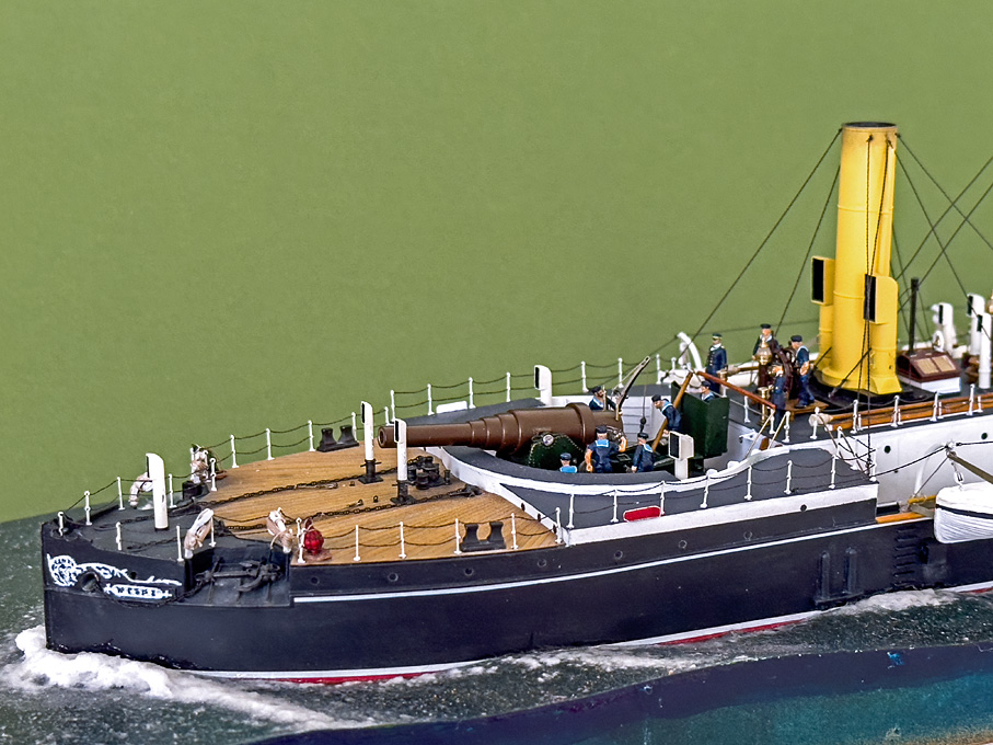
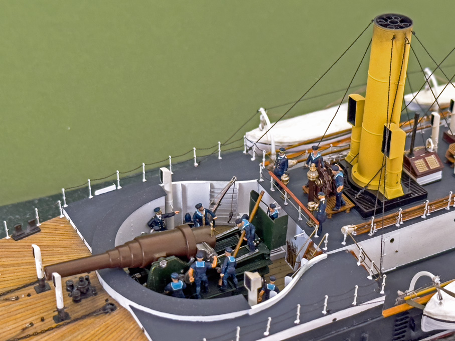
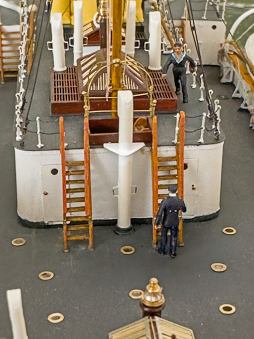
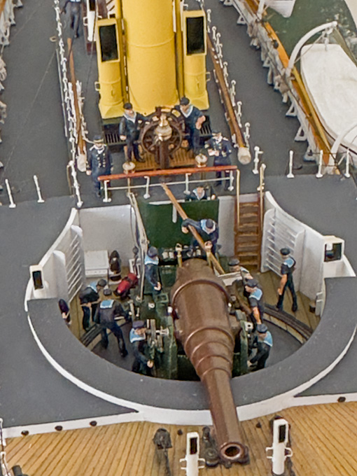
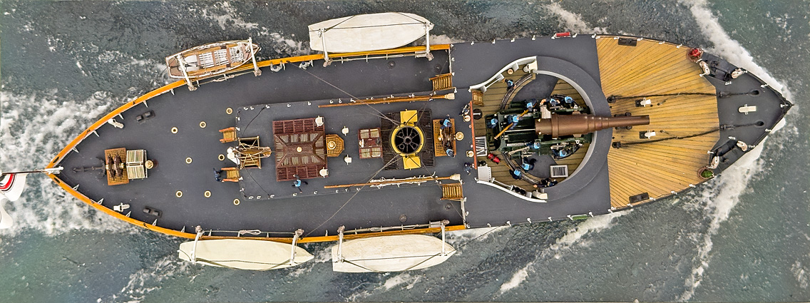
The Crew boards S.M.S. WESPE
With all the crew members being painted, they were place at their foreseen duty stations. They were attached with tiny drops of Vallejo acrylic matt varnish. The pictures below show their disposition.
Final touch-ups
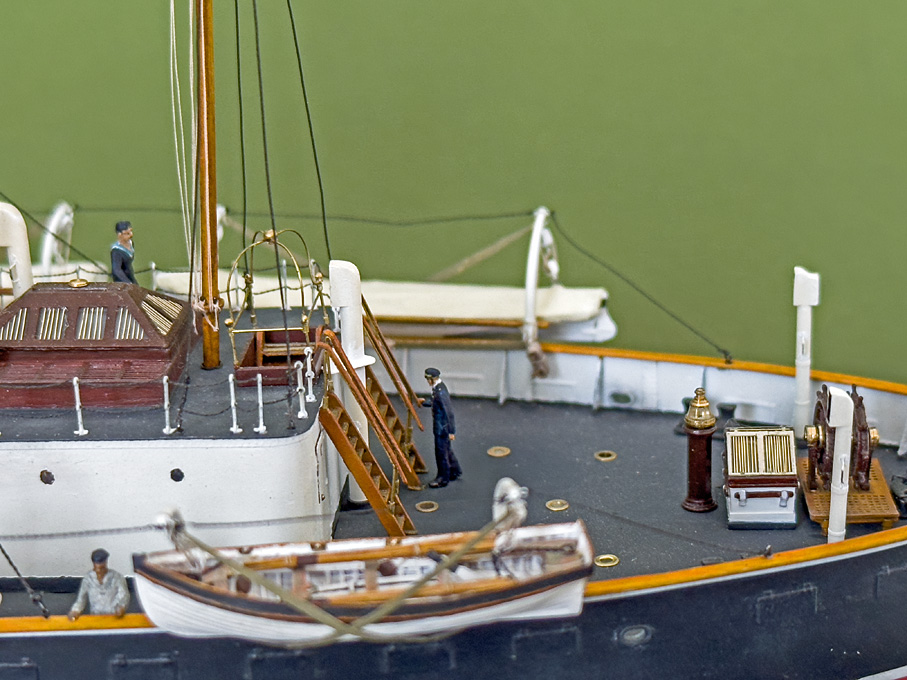
In case I had to remove the model from its base for whatever reason, it had only be screwed down, but the slight gap between the hull and modelled sea had not been filled with acrylic gel yet. Now with the model almost completed, this was done.
I also gave it a very light weathering at certain places. For instance, the top of the smoke stack was lightly dusted with black pastel. White and grey pastel indicated the areas where the ash would have dropped out of the ash-chutes into the sea. Some grey pastel was also applied to certain parts of the hull to break somewhat the uniform black and enhance the visibility of surface structures.
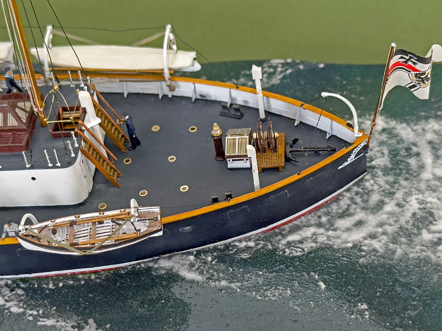
Raising the Ensign
Now, being ready to go to sea, the ensign was raised, meaning the flagstaff was installed. This being extremely delicate, it was left as very last step.
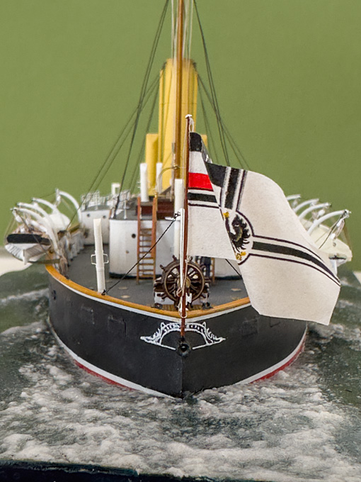
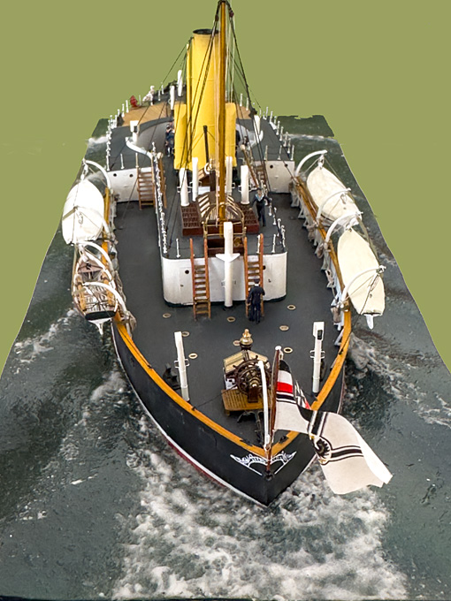
With this the model is in principle finished after a journey of nearly 18 years. I just checked: the first photographs were taken on 1 October 2006. There have been considerable interruptions, such as the move from the Netherlands to Paris. I also built the model of the Zuiderzee-botter in between and spent considerable time on constructing workshop tools and machinery.
However, before screwing down the glass-case the above photographs also serve to check the model for any imperfections that can still be addressed at this point. Paint may have to be touched up etc. This is more visible on 2D images, than on the real thing. Once this is done, some ‘glamour shots’ will be taken before the glass-case makes this more difficult.
There are certainly things that I wish had turned out better. This includes the rigging, which is taught or following catena-curves as I had planned. Making things to scale-size also makes them at the chosen scale rather flimsy with limitations to adjustment possibilities. This is even more the case with ‘modern’ ships in metal and with metal parts, where parts have to be thin and small, compared to those on wooden ships of old. Sometimes, these problems also arose due to a lack of foresight on my side.
What next?
Well, the follow-on project is mentally already almost completed (one of several), but the workshop needs first a good tidying up, cleaning, and re-organisation. Something that had been neglected actually for several years during the drive to complete SMS WESPE. Some machinery also needs a bit TLC to be ready for the next project. There are also a couple of small tool projects that I want to undertake, but I may start those only, once I have started the new ship project.
-
It's good to see that certain old-school techniques, such filing buttons, find new applications, here to get the shape of the prop tube right 👍🏻
- Glen McGuire, mtaylor, Keith Black and 2 others
-
5
-
It will be almost a shame to hide all this wonderful metal work under paint ...
- michael mott, FriedClams, druxey and 11 others
-
14
-
Soldering is joining two metal parts with another metal that has a lower melting point than the parts to be joined.
There are some low-temperature solders with a melting temperature less than white-metal (which I assume are your parts). Some railway modellers solder their white-metal kits and there are some hints on the Internet concerning fluxes and solders. You also need a temperature-controlled soldering iron to make sure you stay below the melting point of white-metal.
Given the risks involved when trying to solder these kits, it seems that railway modellers in general prefer epoxy cement. CA does not have sufficient gap-filling capabilities.
- mtaylor, Canute, michael mott and 1 other
-
4
-
It will also depend on the top-gear of the vessel, i.e. how many men one needs to bring into the mast quickly to take in sails.
On some ships the first or last shroud may also have been slackened in order to allow closer bracing-up of yards or to let booms swing out further.
However, I doubt that any useful information can be found for 16th century ships. Perhaps there are some paintings, but at this time painters were rarely that well informed about such details.
- GrandpaPhil, mtaylor and CDR_Ret
-
3
-
It was used throughout the days of gaff-sails to quickly take out the 'draw' of the sail. One can see this on many paintings, particularly of smaller boats with gaff-mainsail. It reduced the power of the sail wihout putting in a reef, which is a rather complex procedure.
On some ships the tackle to the tack was led to the boom, while on others it was led to the deck at the mast. It was also an early use of chain, rather than rope.
-
Well-done, that looks almost like the 'real' thing.
I didn't read again from the start and apologies, if you discussed this, but wondered, whether these 'chamber-pieces' were really fired from wheeled carriages. I thought they were only used for tranportation. It would be rather difficult to control the considerable recoil without any tackles and such. I though the guns would be placed flat onto the ground to profit from the friction and perhaps wedged down. Any insights on this?
- Keith Black, mtaylor and druxey
-
3
-
On modern reconstructions/restorations, they typically bevel the planks that there is a gap of a few mm on the outside. This is necessary to avoid splitting the wood with the caulking iron by accident.
Deck-planks on iron and steel ships often seem to have a groove planed in half-way down the thickness in addition to the bevel mentioned in another post above. This served as a sort of 'reservoir' for the oakum, preventing it from being squeezed out, when the planks became wet and expanded and acting as a seal, when they shrank on becoming dry.
-
There was a special tool to unload muzzle-loading guns. It looks like a cork-screw, but with two parallel wounded screws. With this the ball could be extracted, which was slightly undersize and the wads that kept the ball in. For the powder a wooden shovel the size of the bore was available.
However, unloading the charge was a rather dangerous operation, as one could imagine.
Unloading of later breech-loading guns was a bit simpler and somewhat less dangerous. Normally, the bag was loaded in silk bags that could be pulled out and put back into their transfer containers. The rammers for the projectiles could also be used to unload them by pushing from muzzle. For this the rammers were hollow in order to clear the fuse. In gun-drill no 'hot' charges were used and special drill-shells, both of which where filled with saw-dust/sand mixtures that had approximately the same weight as the powder.
The barrels of early breech-loading guns would wear out rather quickly, so that, apart from the cost, rarely practice shooting was undertaken. Apart from the mentioned gun-drills, target practices involved e.g. a small-caliber inlay barrel or even a hand-gun barrel.
There are maintenance manuals and instructions available from roughly the middle of the 19th century for several navies.
- mtaylor and thibaultron
-
2
-
It's indeed one of the few maritime/naval museums that has not yet been given a new 'mission' by museum specialists that have no clue of (and interest in) the actual subject.
It has a wonderful collection of large-scale models. A very personal selection from repeated visits here: https://www.maritima-et-mechanika.org/maritime/madrid/madrid.html
- mtaylor, Harvey Golden, cotrecerf and 2 others
-
5
-
I think on earlier boats these connecting rods (as they would be called on locomotives and the likes) were indeed baulks of timber.
I gather the opening in the cladding would have been kept as small as possible to keep spray from the wheel out. Wouldn't have been there be quite a bit of repair on those boats, so you may be able to patch up the existing hole a bit.
- Keith Black, KeithAug, FriedClams and 5 others
-
8
-
I prefer collets for small parts, much safer and more precise. Does the Atlas have a taper in the spindle and is it bored through?
- thibaultron, Canute, druxey and 2 others
-
5
-
What's the material? They look rather grey, like die-cast zinc.
- mtaylor, Canute and thibaultron
-
3
-
-
Thank you very much, gentlemen, for your kind feedback !
***********************************************************
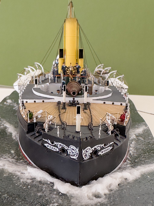
More Crew
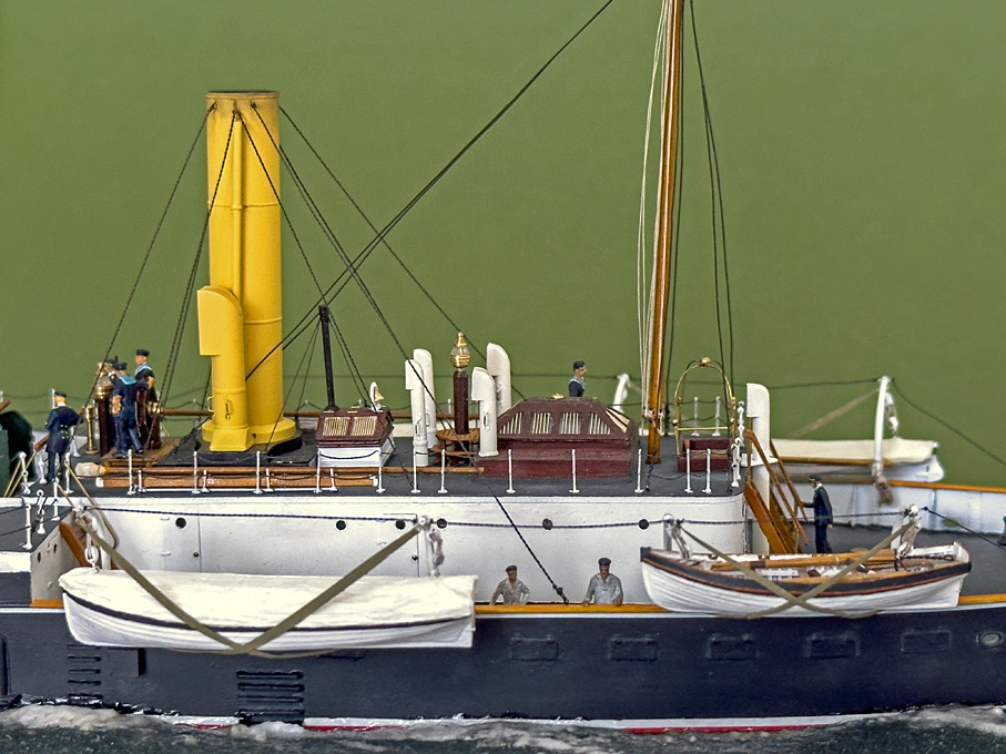
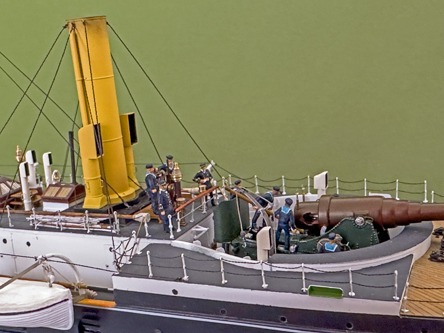
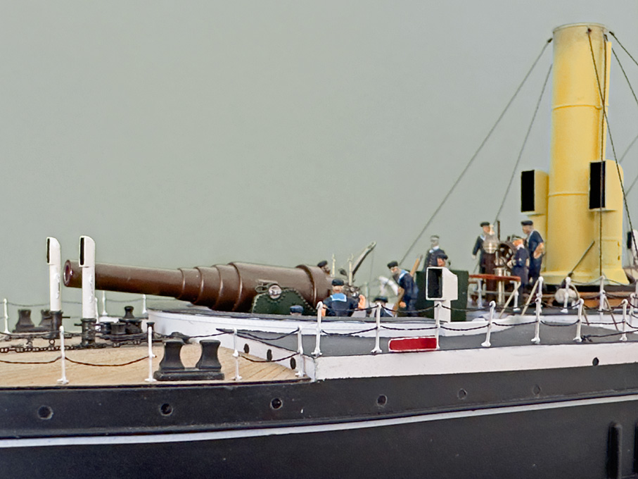
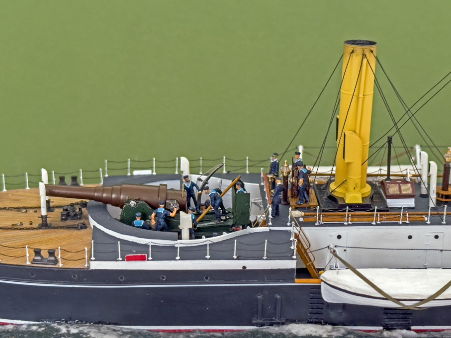
While dispositioning the crew according to the envisages story-board - the crew undergoes some gun drill under the supervision of a petty officer, with the captain (Kapitänleutnant, but I didn’t manage to paint the two embroidered stripes on the sleeves) looks on, the first officer (Leutnant zur See, one stripe on the sleeves) takes notes, and two men man the helm - I noticed a certain emptiness and lack of activity in the other parts of the boat. So, I sifted through the Preiser-sprues in search for some additional suitable figures. Thus, more mid 20th century German railway staff joined the 19thcentury Imperial Navy. There will be two stokers taking a break from their arduous work, a rating on signalling duty walking back towards the mast, and a petty officer on the after deck going about his duty.
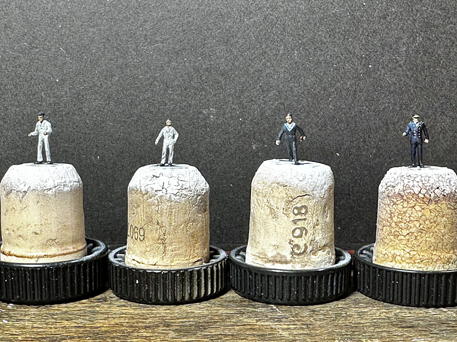
As before, jackets had to be trimmed down and breast pockets scraped off in order to represent blouses and high-waist trousers. The single-breasted railway-jacket was converted into the double-breasted one of the navy, caps or hats altered.
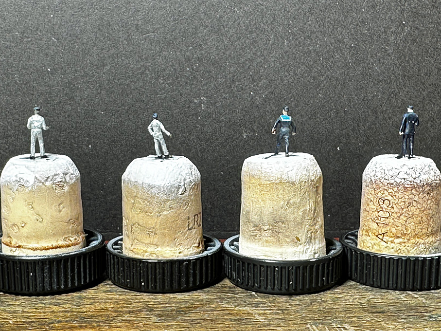
The painting proceeded as before, but I noted that the practices from the other figures paid off. The stokers wear the white working blouse and trousers, which seems a bit strange in a boiler-room environment full of coal-dust, soot, and sweat, but I suppose the undyed cotton stands up better to serious washing than any coloured cloth. After painting, these figures were dusted with grey pastel.
To be continued ....
- Bob Cleek, tmj, Roger Pellett and 11 others
-
14
-
As to the the disposition of the figures, it is useful to make a sort of 'story-board', at least meantally, that notes down what is happening, who is involved (officers and ratings), and how many are needed for the task.
- Jay 1, mtaylor, Glen McGuire and 4 others
-
7
-
The long beading needle are good idea, as they allow you to align the ratlines properly before you pull the thread through 👍🏻
- FriedClams, Glen McGuire, mbp521 and 3 others
-
5
-
 1
1

1880's Floating Steam Donkey Pile Driver by Keith Black - FINISHED - 1:120 Scale
in - Build logs for subjects built 1851 - 1900
Posted
Artists pastels are good for such weathering. White, grey, black and some olive green for around the water-line. The originals would have treated with a solution of tar, but your wood resembles already that.