


Wintergreen
-
Posts
1,002 -
Joined
-
Last visited
Content Type
Profiles
Forums
Gallery
Events
Everything posted by Wintergreen
-
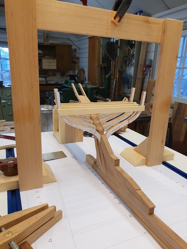
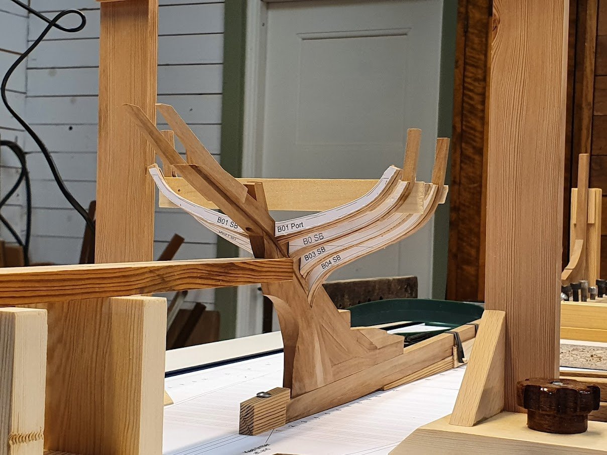
Vaddoc, well, that remains to be seen, doesn't it? And I also am looking forward to see if it will come together. Anyway, it's been a while and I was not released from hospital on that particular weekend. Instead it became almost three weeks in hospital with an additional surgery Fri April 1st. It's a story for itself and I will not recapitulate it here. Status now is that I need IV every day to keep my fluids balanced and I can be up and about for a hour or so before pain takes the fun out of it. They've been rummaging about in my lower abdominum and it takes a while before it "sets" again. Hence the pain. Boatbuildingwise four frames are now in place. Frame no 4 was prepared before my hospital experience and today I felt good enough to glue it in place. It looks like this: Four frames done means it is 32 to go...well, one at a time. Slow and steady, slow and steady. Finally, thank you for likes, comments and well wishes!
-
Wheel looks okay I'd say. Well salvaged 🙂 Keep it up!
-
Looks like a good old cabin or deckhouse to me 🙂 Keep it up!
- 118 replies
-
- 3
-

-
- billing boats
- meta 484
- (and 1 more)
-
No John, it's not! 😄 I have managed to build and mount three frames. It's a finicky business to say the least. On another note, the surgery is done and I'm currently in the hospital. Will be released this weekend as it looks right now. Belly looks like a Swiss cheese with all the patches... Restrictions are no lifting. No cycling. Nothing heavy for at least 4-6 weeks. Modelboat building should be okay though. 😉 Spirits are, if not high, on a modest level anyway.
-
Changing subject is always a good diversion for the mind. And by somemagic the brain works in the background coming up with solutions or inspiration tot he previous task. 😉
-
Nice! Have two books on my wish-list 🙂
-
I too have seen wheels mounted to the side. Awkward - yes. But it saves a 90 degree turn for the steering cables at least. Twin pot petrol sounds likely. But what about a SABB diesel 😉 Link to youtube Keep it up!
-
@KeithAug, @FlyingFish Thank you guys! Yes, I try to keep an upbeat note to this crap called cancer. Makes it easier to bear. Stay tuned for more updates on my build... I feel there are frames coming soon...
-
Yes, sorry about that mess. Probably should sort it through also. 😋 On another note for those who are interested, not shipbuilding, I'm done with the chemo since last Wednesday. Follow up x-rays revealed that the tumor had significantly diminished in size. Next up will be a preop meeting with the surgery dept in 1,5 weeks. Still suffering from side effects though, and I'm still very tired. But the sun is shining!
-
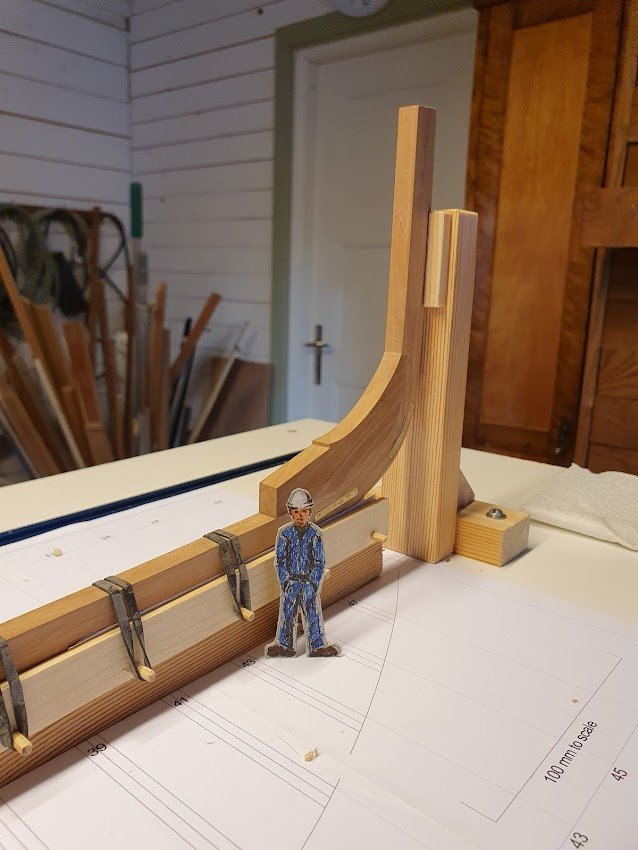
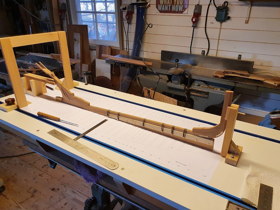
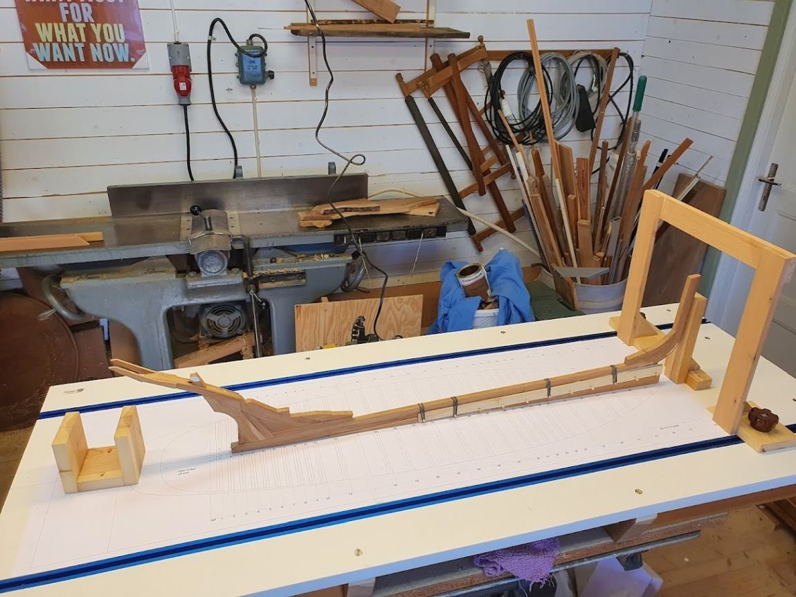
Hi guys, Quick status update. Over the last weeks I've been preparing framing. That meant, 1. Finish the centreline structure 2. Print the framing plan for the shipway and all plans for the frames 3. Build and mount the slanted keel support 4. Glue the plan to the shipway 5. Build end supports to hold the ends (no duh 😄) 6. Prepare wood for the frames Bullet one was fairly quick since the only parts missing were the fashion pieces. After some trimming they aligned with one another. Bullet two was really easy. Got that done before I went on 100% sick leave. Bullet three took some time. However, I didn't really think it through since I mounted the keel support prior to gluing the plan on the shipway. I had some challenge in getting the plan at the correct place in correlation to the keel. But what would building scale model boats be without a challenge or three?? Anyway, I solved it so now the plan and the keel are on par with each other. The plan I glued with spray glue after carefully masking off all adjacent surfaces of the shipway. Finally, the stem and stern supports. Inspiration was taken from EdT:s Najad build vol 1, where he describes both the shipway as well as supports and other stuff. And finally finally, the most time consuming task, milling timber to scale thickness. I have yet to decide whether to use birch or apple. Probably I will do a couple of test frames. In calling them "test frames" I hide the issue of redoing stuff. Clever huh? After all this text, some pictures. (don't mind the background mess) And Karsten is happy as Larry (just learnt that expression 🙂)
-
What is the guy with the yellow coat small mallet doing in this picture? To me, it seems he would need a bigger sledgehammer to drive those bolts in 😄 Looking good Siggi!
-
Re about other projects in the background - it's like a proper boat yard I'd say. There are always several ongoing jobs at any given time. (just found this log) Bluenose looks good. Tall and proud masts also. I guess, when you look at sailing photos of these era you can get a appreciation for the sheer amount of canvas and actually how tall the masts were (are). Especially if you can spot a rigrat handling the topsail when tacking. Keep it up!
-
Deck looks good. Shifts are laid properly with three shifts lengthwise and four sideways. Nice 🙂 Out of curiosity, why did you plank the aft deck in line with the bulwarks while the main deck is laid for and aft? Usually work boats had their decks laid for and aft as I understand. If it was just for fun, then it's all right, your the shipwright 😉 Keep it up!
- 118 replies
-
- 1
-
-
- billing boats
- meta 484
- (and 1 more)
-
Well, it's a sensitive thing to do, put it aside for the time being. Maybe you will find the inspiration to continue later on. No worries. Cheers
-
Yes, the stern and the galleries are quite intimidating to say the least. But, look through the various bits and pieces and make a step by step plan. I'd say that part of the ornamentation can be attached after rigging is done. Like all the figurines on the side galleries. They will for sure be up to the task of being regular pita:s. Catching a stray sleeve or a stray line or so and then launch themselves into the abyss never to be found again 😉 Just take it a step at a time.
-
Always a good idea to have the hull secured in some kind of cradle or stand. Your padded version will aid when you tilt the hull to get a more convenient position for detailing. Good work, keep it up!
-
Looks about right to me, the planking width that is. Good progress Bolin. Keep it up!
- 118 replies
-
- 2
-
-
- billing boats
- meta 484
- (and 1 more)
-
@clipper-Tony, if the online PDF:s doesn't cut if for you. I mean, print shops might have problem with the COPYRIGHT watermark, I have the plans and can possibly have them copied locally and send them to you. Just send me a PM. Cheers
-
Hi Tony, So sorry for your loss! Can't image what it's like to loose a sibling, even so a twin. Hope you find the strength needed ❤️ About plans, will this link prove useful: https://www.billingboats.com/index.php/modelboats-footer/75/120/boats/the-expert/P-bb490-wasa There are two downloads. One for the construction and one for the rigging. It says copyrighted on the rigging plan but you easily see through that text. Might it work?
-
Well done on the cupolas Johnny! On my 1985 kit I only painted them and did not try any shingles or so. Might possible draw shingles on them if I get to renovate the ship. Reason is to not get too out of scale. That is always a risk when working at these smaller scales. Very nice planes also. Talented father obviously 🙂 Keep it up!
-
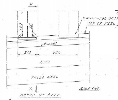
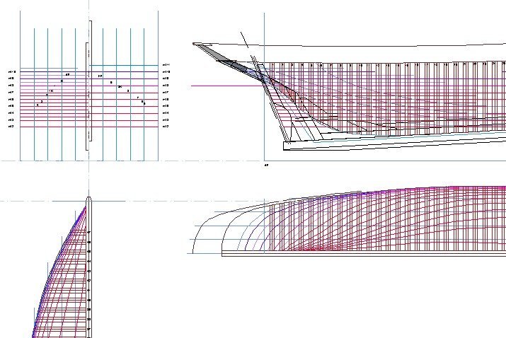
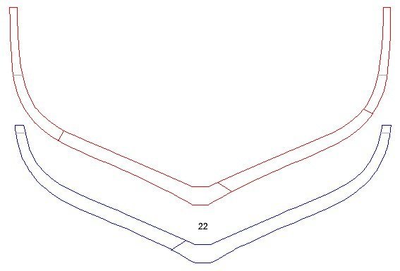
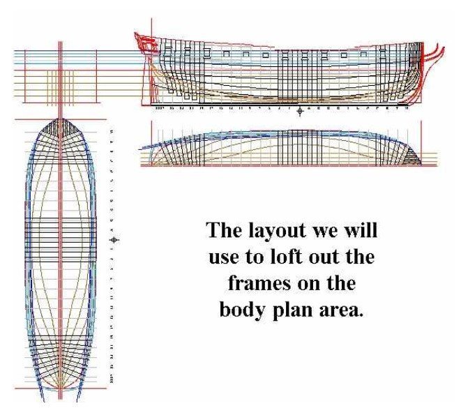
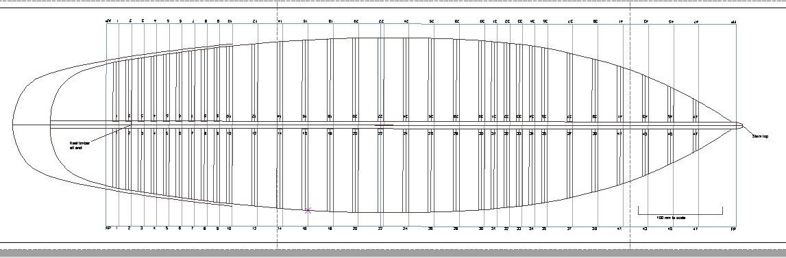
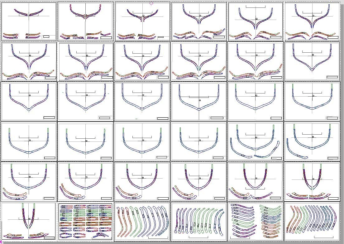
1.2. Frame lofting party All Atlantica’s frames are double from sawn timber. All necessary details can be found in the construction drawing. From the latest lines plan, create a copy and start by removing all station lines from it. Instead put in new station lines corresponding to the given distance for frames. On older drawings usually called room and space. Room is the space the frame occupies lengthwise and Space is the distance between two frames. In the detail above the room would be 210 mm and space 450 – 210 = 340. To get consistency throughout I copied the entire center structure from my Construction keel plan. That way everything matches up with timbers and deadwood. On the keel plan I also had already marked where most frames would be. A bit of cleaning up was needed to get rid of some surplus lines. I used the rectangle tool to create the first double frame and then did a linear copy to create the lot. Then a lot of trimming and numbering and I’m all set. One thing missing from the construction plan are details about futtocks. That is the members of the frames. There is no clear evidence in the book either apart from them using quite few futtocks for each frame. From what I can gather from all pictures no more than maybe 6 members for each double frame. The practice seems to be to mirror the futtocks for each half of the frame. That is my best bet and it will also limit the number of members in total. As a practice run I lofted the widest frame, no 22 it turned out to be. Red depicts the aft face of the aft members and blue depicts the forward face of the forward members of the frame. The grey line is waterline 8 which is also the actual waterline and it is marked out for being a good reference point when mounting the frames. The taper or siding is also a bit of guess work and what looks good. The top and bottom ends are given by circumstances but the taper in between is just been shapely made up. After a couple of more practice runs I started creating frames from aft working on forward. A decision was also made to omit frames that did not have stanchions on them bar the aft 10 frames. They will all be done. The reason for this is to reduce the labour of framing the ship on my behalf. The process of drawing the frames are quite straight forward as described in Wayne’s treatise. Simply, on the sheer plan, construction lines are set at every crossing between a futtock line and station/frame line. The futtock line describes a curve. On the half breadth plan a construction line is set at every crossing between a water line and station/frame line. These two sets of construction lines converge in the body box. Then it is a matter of tracing these intersections and voilá, you have a frame line. I take the liberty of a screenshot from Wayne’s treatise to show the setup of plans. It will give you an idea of how it works with construction lines and all that jazz. Of course all this takes place after the plans have been faired. Nevertheless, bumps appear when the frames are lofted. It is hard to have plans 100% faired for all station, water and futtock lines. Take it as sanding margin. After all frames are lofted comes the work with exploding them into separate members for templates to use when cutting timber. I choose to put most members on separate sheets. Every sheet has the centreline and waterline marked for easy adjustment and lining up when building. All 36 frame sheets are shown in the screenshot below. Size is A4 for easy printing. As can be seen in the screenshot above, three colours are used. Green is used for the aft most face of the frame. Red is used for the middle face of the frames. Remember, each frame is double. Apart for the frames in the middle of the ship where the red is omitted due to the small or little bevel on these frames. Blue is used for the forward face of the frame. The templates are printed to be glued on the forward face of the forward frame pieces and on the aft face of the aft frame pieces. Hence the aft templates are mirrored for this purpose. Since I had the CAD up to speed, work continued on the frame plans for the shipway or building board. I have understood that it simplifies greatly to have the ship built upon a framing plan. Then it is a matter of setting the gantry on the frame line in question. The keel and centreline structure needs to sit firmly in place on the shipway though. Here is a screenshot of the framing plan. For my own convenience it is printed on three, size A3 papers. As it happens there is an A3, colour printer at my work... what a coincidence. Each frame is numbered and there is an additional line where the keel ends. Also in this plan can be seen the gaps where frames were left out. One might wonder why there is a gathering of frames at no 30-35. That is because the main mast goes there and more stanchions are needed for the pin rails. The same goes for frames six through ten. With all this work done some building can take place. Next item up for drafting is the deck structure with deck beams, carlings, hatches and bitts and stuff. Thank you if you read all the way here. I hope all this text makes at least some sense. Til next time, ta!
-
Nice paint job. Those closeups always a bit intimidating. Seeing your build I am more an more tempted to renovate my own old build... Keep it up!


