

DelF
-
Posts
1,398 -
Joined
-
Last visited
Content Type
Profiles
Forums
Gallery
Events
Posts posted by DelF
-
-
Many thanks for the kind words B.E.
1 hour ago, Blue Ensign said:The only downside of looking at your log is that it cost me money, another three items of interest to follow up including those wonderful looking chisels.
Having spent the last several years gaining inspiration and ideas from your build logs from Pegasus on, I think it's only fair that I should pass some ideas/cost your way! The chisels are indeed great, but to use them to best effect you really need the honing guide from Richard Kell, a toolmaker from Northumberland. Here's a link to a recent discussion on the subject, with a link to Richard's website.
Have a very happy* Christmas and a peaceful New Year.
Derek
* I think I was the one that confused Glenn on the happy/merry point; I always get it wrong!
- Blue Ensign, glbarlow, chris watton and 1 other
-
 4
4
-
-
Vanguard make great kits but they still require care and skill to produce such fine results. Have a happy Christmas.
Derek
-
Unfortunately that doesn’t seem to explain the current problem, at least in my case. I’ve taken a series of photos with the same device, saved them on the same PC and all organised in Photoshop. Some photos in the batch upload fine; others show the 200 error. This has never happened before. Others seem to be experiencing the same issue.
- mtaylor, Keith Black, Canute and 1 other
-
4
-
1 hour ago, James H said:
One thing is for certain, nothing has actually changed here with regard to software updates since December 8th. Are these problems from that point or going back way further?
Happened to me for the first time on Saturday. I’d posted another batch of photos after the 8th before Saturday without problem.
- Keith Black, Canute, hollowneck and 1 other
-
4
-
Thanks Yves and Rusty, much appreciated.
16 hours ago, glbarlow said:...boxwood coupled with the well done decorations make for a stunning look.
Thanks Glenn. I bet you'll raise the bar again with your Winchelsea, especially when you get to that lovely Alaskan yellow cedar.
16 hours ago, glbarlow said:I’ve enjoy our cross-pond dialog this past year and look forward to more next year.
Me too, although we'll have to keep the tool recommendations to a minimum in future in case our spouses start to wonder what's happened to our retirement funds!
- Ryland Craze, chris watton, Rustyj and 2 others
-
5
-
As B.E. says, a wealth of interest and great photos. My Sphinx is still in her box but itching to get out when I read your log!
Best wishes
Derek
- mtaylor, Ryland Craze and hollowneck
-
3
-
The error is still there. I had one photo rejected just now, out of seven. As before, saving it under a different name and reloading it solved the problem.
- Keith Black, glbarlow, Canute and 1 other
-
4
-
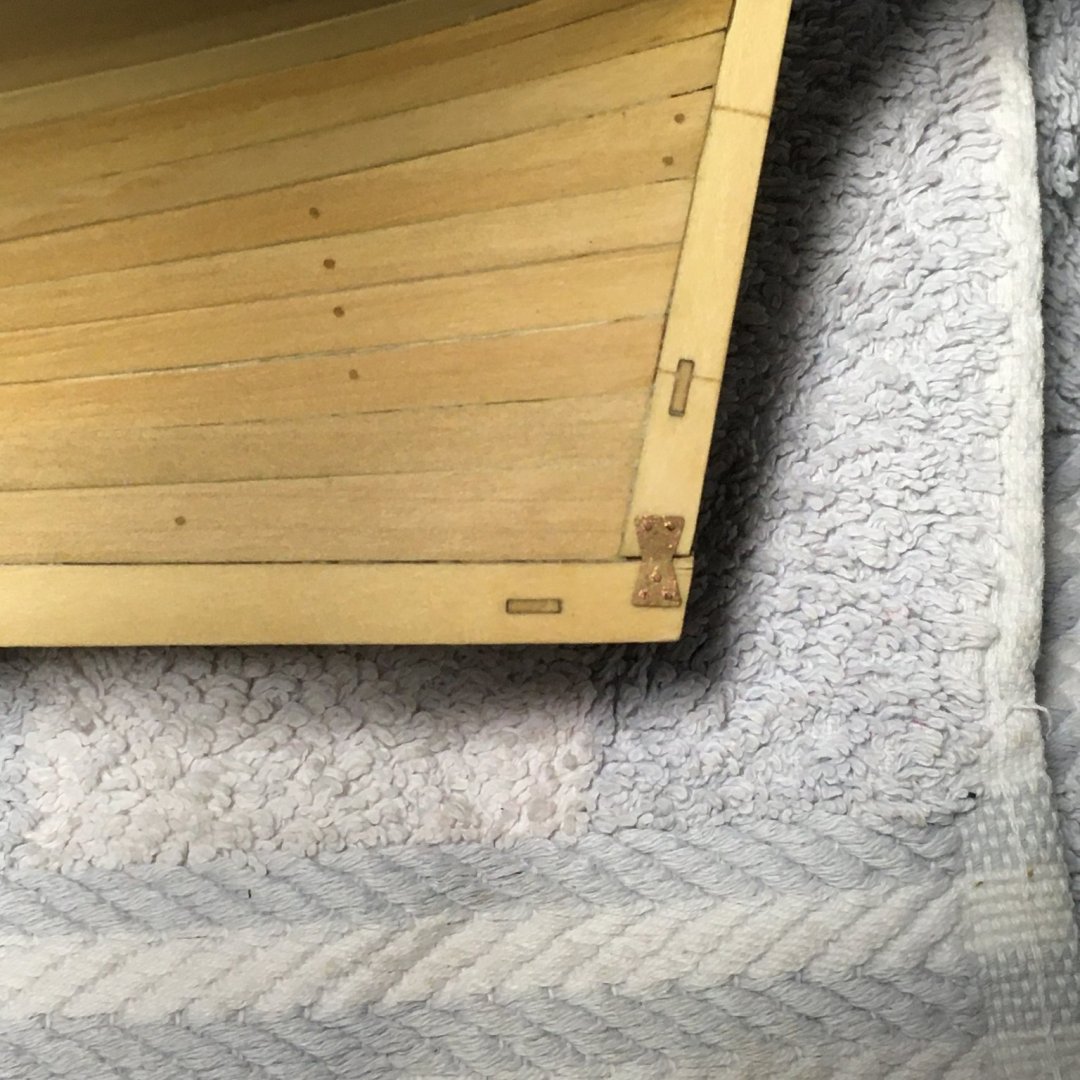
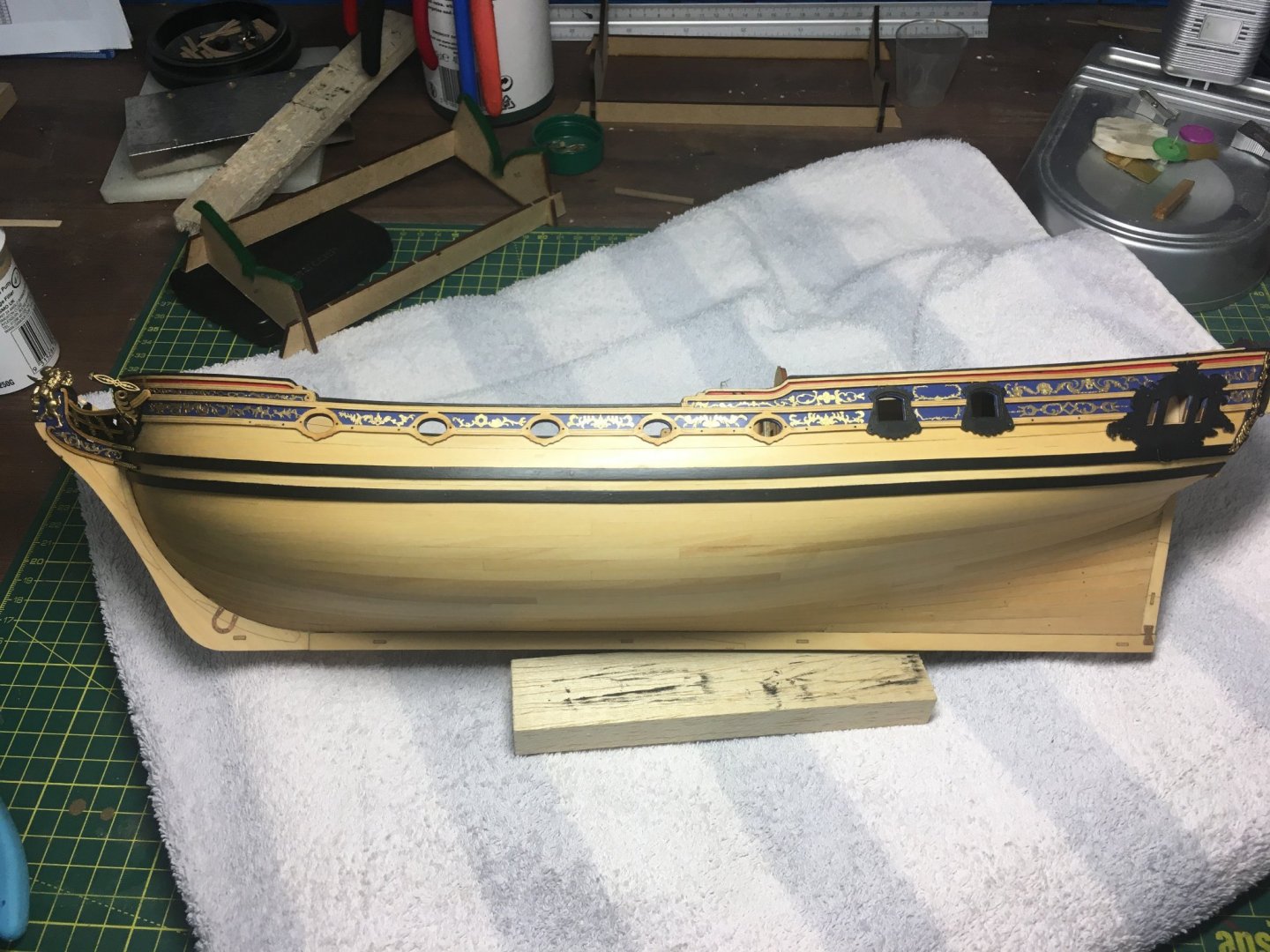
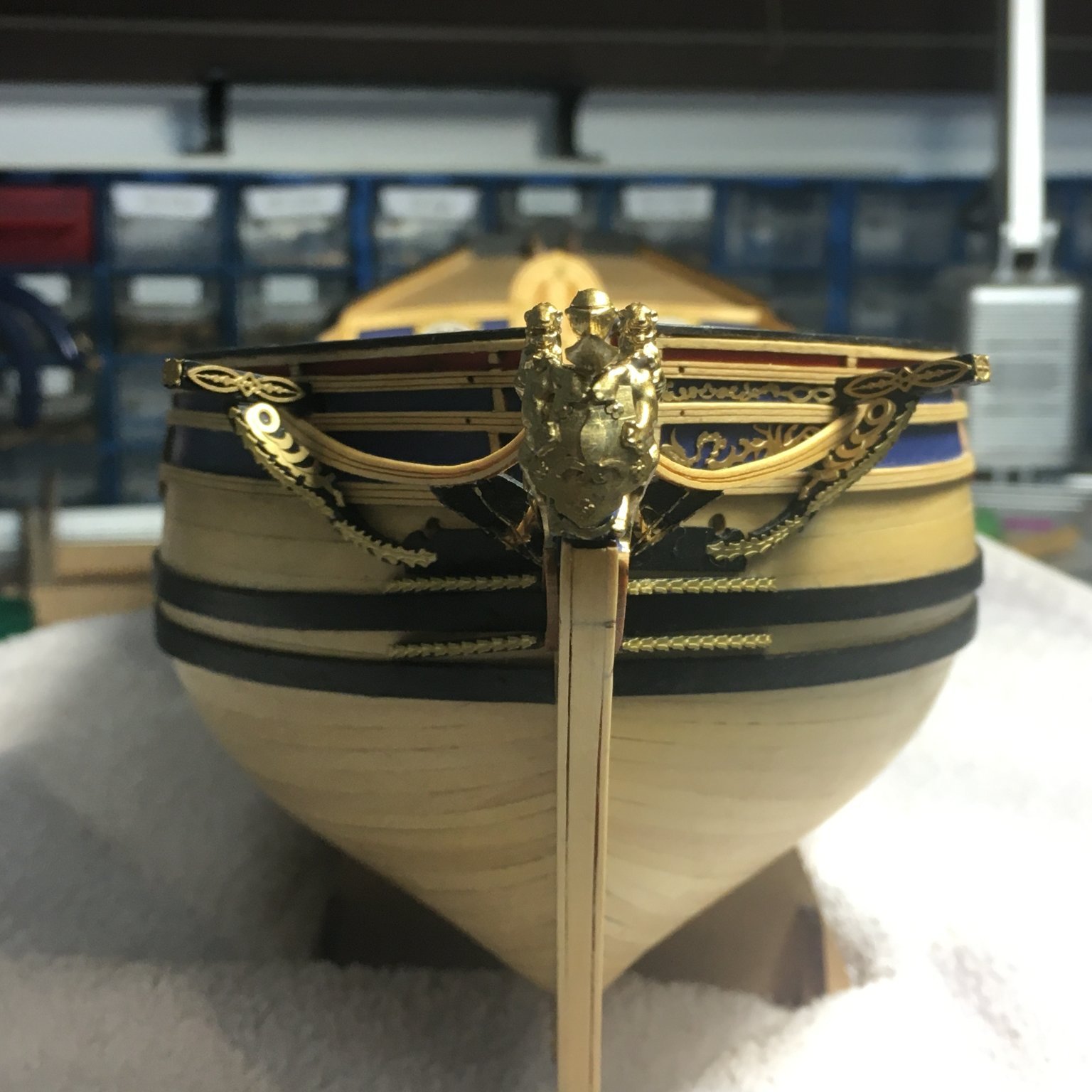
Completing the decoration
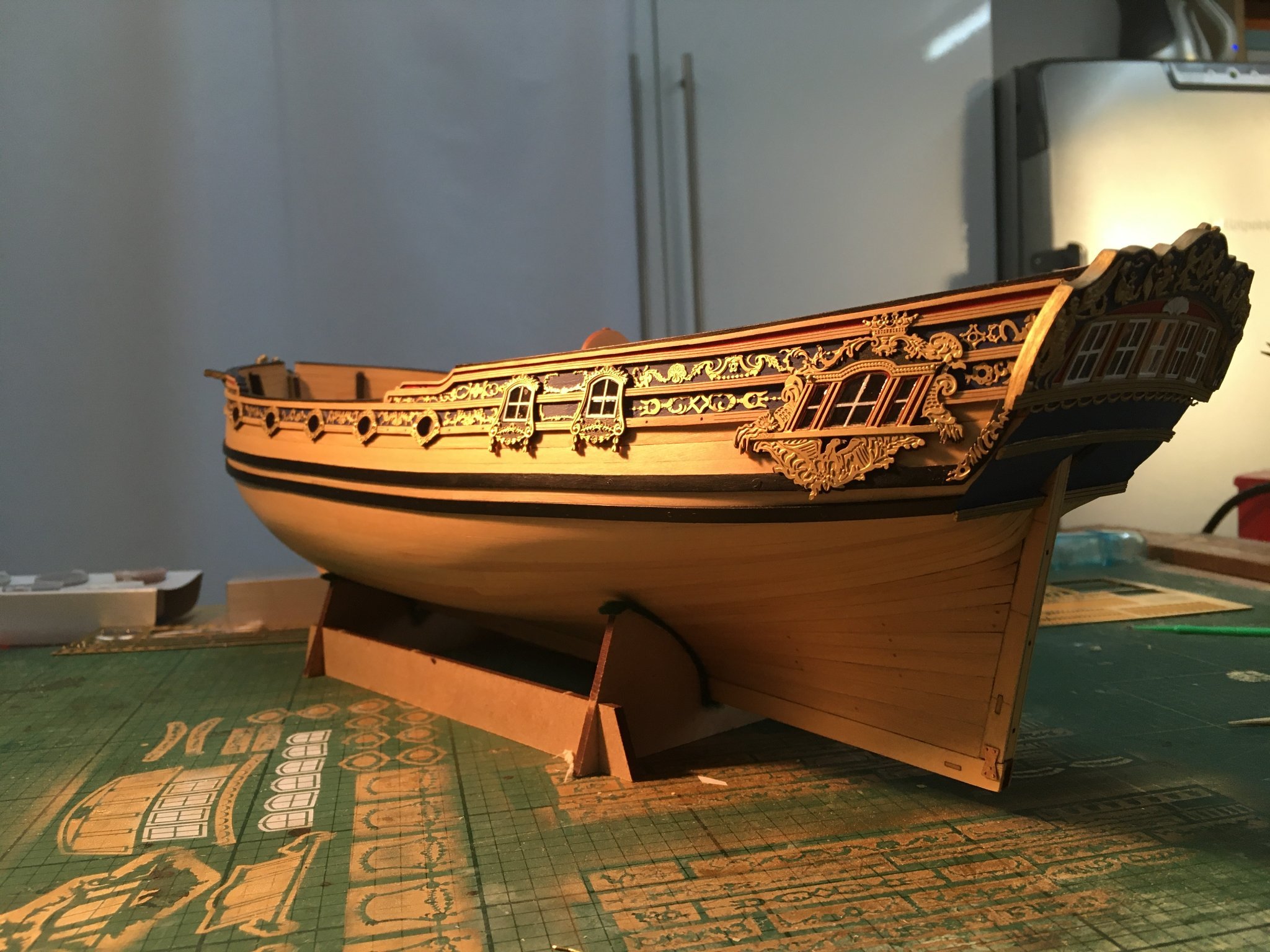
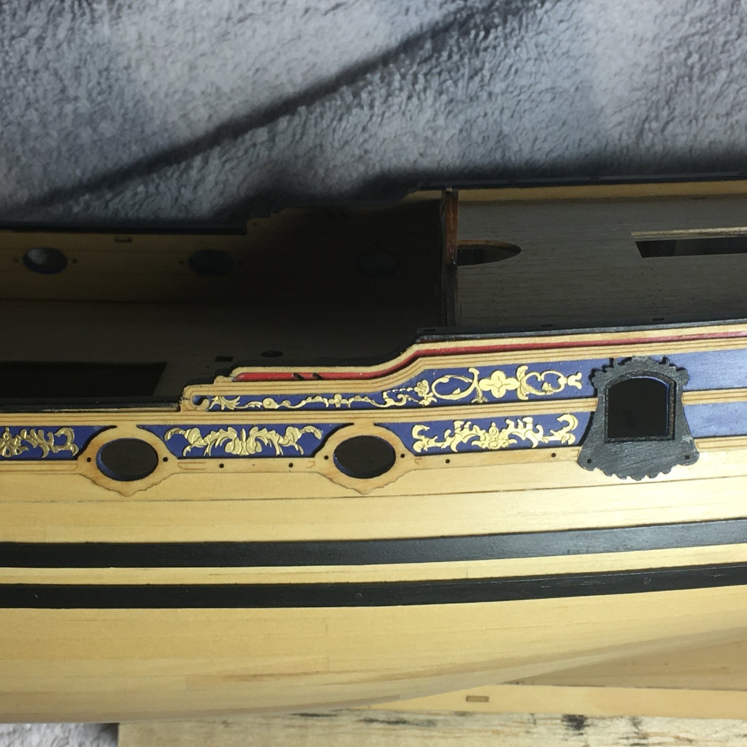
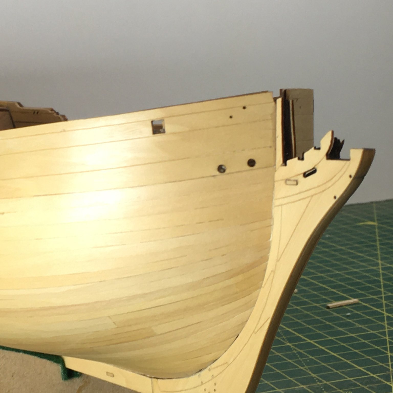
Finishing the starboard side decoration and then fitting the oval surrounds to the gunports was all straightforward. I fitted the four small side windows next, having glazed them using the same technique as on the stern. As with the decoration, the port and starboard sides are very slightly different - the windows will fit in the frames on either side but will not look right if not on their correct side. Again, careful study of the plans and manual is essential. Here's the port side gunports and small windows fitted:
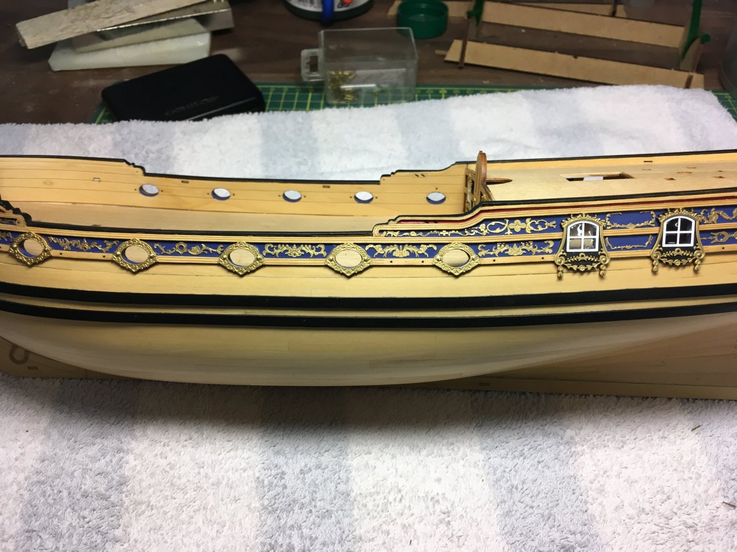
When it came to gluing back the tiny dangly bits that had broken off the wooden window surround, I found it easier to glue them to the back of the PE surround before I fitted the latter in place.
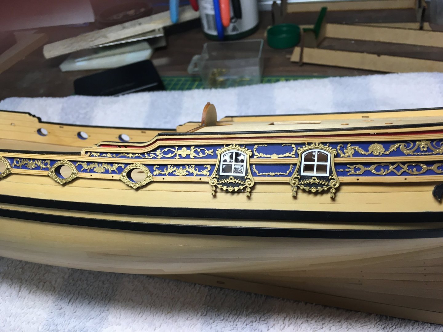
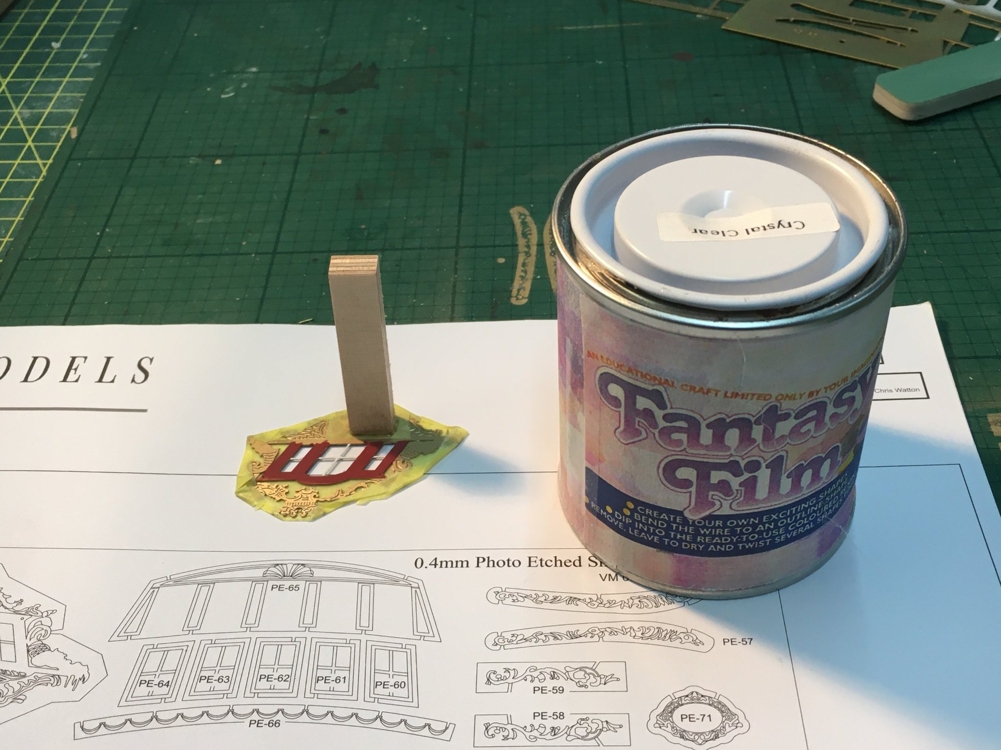
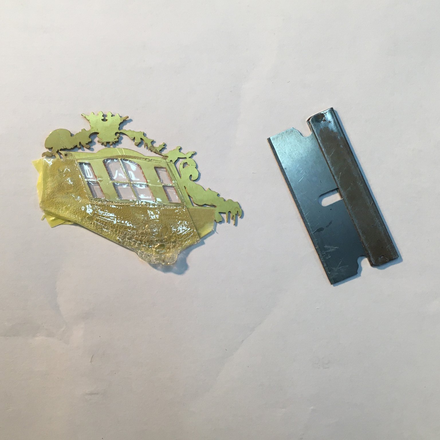
Next, it was on to the large windows at the aft end. These are ornate objects pierced with several holes that I did not want to glaze, so the first job was to cover all but the window openings with masking tape. Also, the windows were too large to allow me to use tweezers to dip them into the glazing solution as I had with the smaller versions. Instead, I stuck a piece of scrap wood to the front of the PE, giving me a handle that enabled me to dip the window flat against the surface of the Fantasy Film:

As before, the trick was to allow only the back surface to touch the film, then to withdraw it as quickly as possible and hold it in the vertical position while the excess film ran off the bottom edge. The first window worked fine. The second took two goes before I was happy. The first attempt left bubbles in the film - I don't think I lifted it quickly enough - and I had to wait for it to dry before I could cut it off and dip again. Once the film was dry I used a razor blade to cut round the back of the window frame so I could peel off the excess film and masking tape:

The next job was to bend the PE slightly to match the curve of the hull. I was reluctant to bend the glazed portion so I wrapped it in paper to protect it and held it in the rubber jaws of my vice while gently bending the bottom, non-glazed part:
Here's the port side fitted:
And a more atmospheric view (ie I got the lighting wrong!):

No prizes for guessing what I used the old cutting mat for!
That's almost all the decoration fitted. I'm holding off fitting the scuppers while I'm still handling the hull a lot. Next job will be the rudder.
Probably my last post for a while, so I'll wish everyone a happy Christmas and peaceful New Year.
Derek
- chris watton, BenD, KARAVOKIRIS and 15 others
-
17
-
 1
1
-
1 hour ago, desalgu said:
You can compare this to others that painted hull white, and to Delf's beautiful boxwood hull left natural. When I look at his, I want to try working with boxwood!
Thanks, but I think yours looks equally good. Take extra care when you fit the upper and lower rails on those V-frames. I found I had to tweak the slots a fair bit to get them to sit correctly.
Derek
-
I had the same problem - must be an issue with the server. However I loaded the photos into Photoshop and saved them under different names, with no other changes, and they then uploaded. No idea why, but it worked.
-
Completing the bow area & portside decoration
Thanks for all the likes and kind comments, they're much appreciated.
Before fitting the various head rails I painted and fitted the catheads. Unlike Speedy, when I neglected to drill sheave holes in the catheads until they were on the hull, I got to work with the trusty Proxxon micro mill before fitting them. The catheads are just shy of 3mm wide, so a 0.5mm mill was just right to cut the necessary holes and grooves:
The cathead support brackets require careful bevelling on each contact face. I found this problematic and ended up disguising a small gap each side with acrylic filler and paint.
As a quick aside, I also fitted the horseshoe and fish plates at this stage. Not a big deal in itself, but worth mentioning as a further example of the kit's accuracy - all the 0.5mm holes in the plates themselves, the two boxwood veneers and the keel itself were lined up perfectly so that all 13 pins went through without a problem:
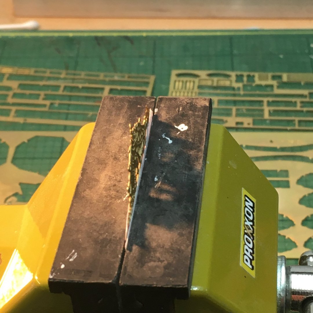
On to the various bow rails and decorations. These were fiddly given their small size, but went together as per the manual without a hitch. The manual is supplemented with detailed 1:1 plans showing the placement of all the photoetch decoration. Given the shear volume of decoration (I counted 30 separate items in the bow area and catheads alone) I found it essential to have the plans to hand to correctly identify and position each piece. Most pieces are asymmetric, meaning the port and starboard sides are different which further highlights the importance of care at this stage. I should add that I grew impatient waiting for the matte medium I mentioned in my previous post to dry, and ended up resorting to CA for most of the photoetch.
Here's the bow area mostly finished:

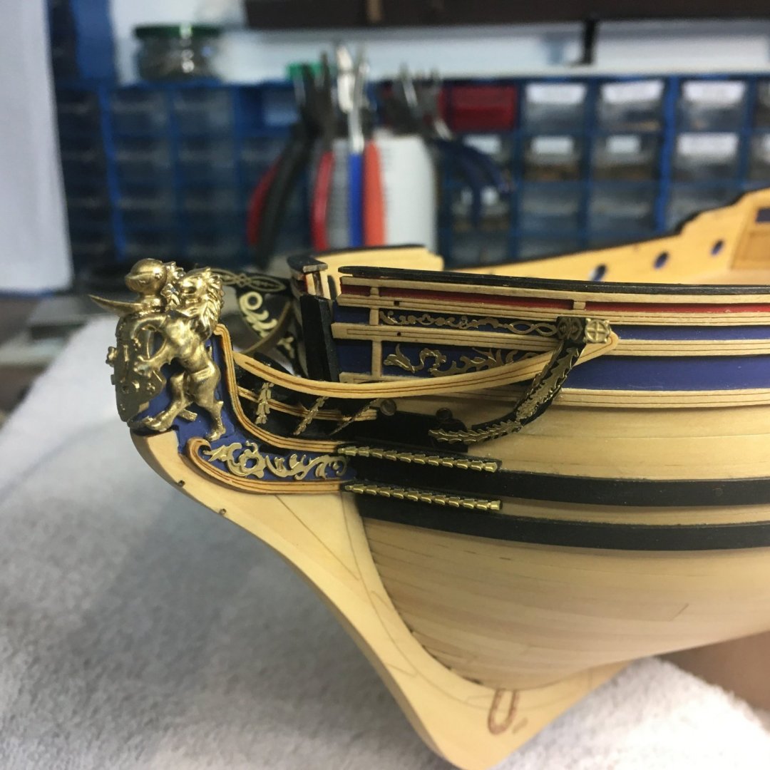
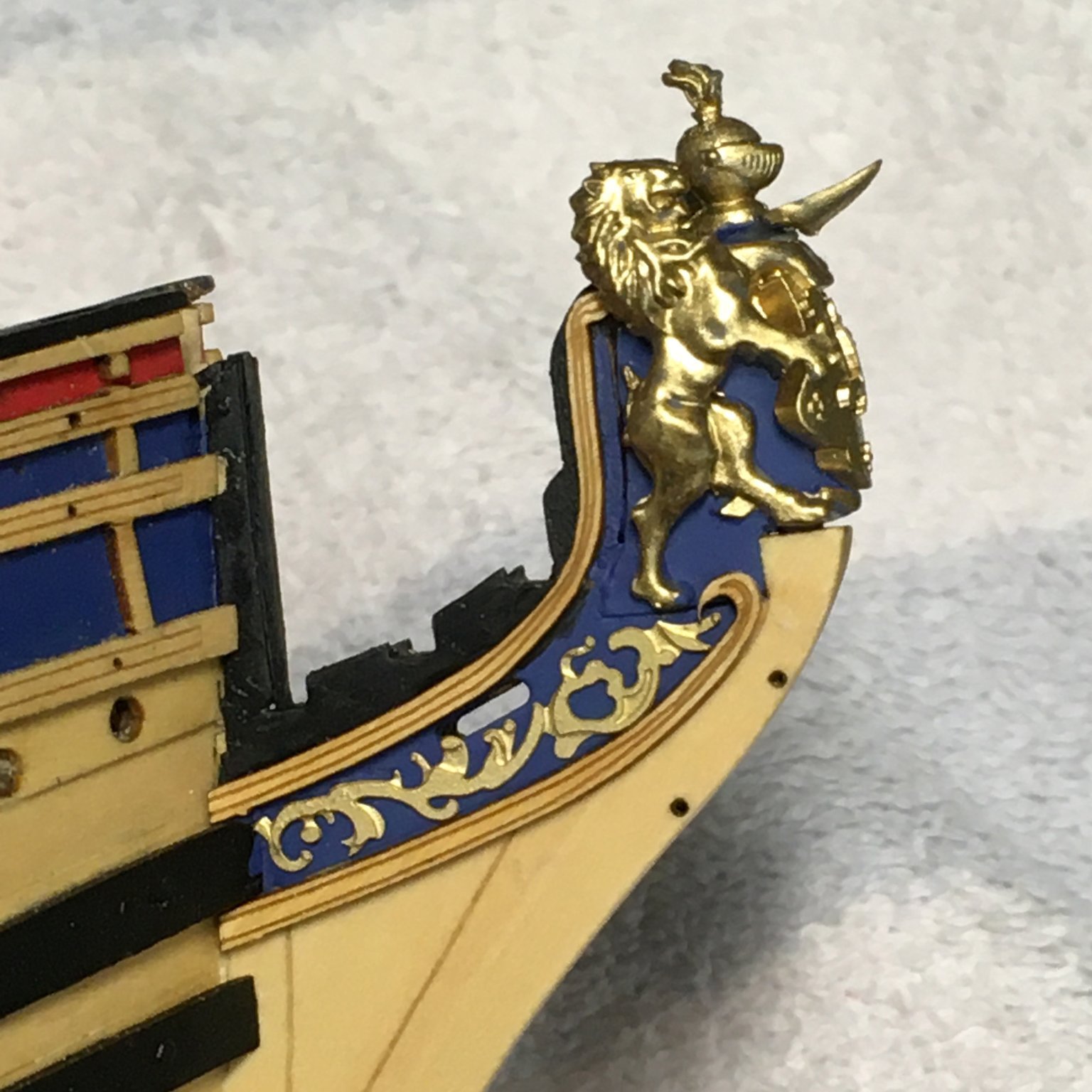
It was around this time that I read @desalgu's Duchess log where he mentioned accidently breaking the plume off the knight's helmet on the figurehead. I felt a sinking sensation as I rushed back to the workshop to check mine. Sure enough, the plume was missing and I hadn't realised 😒. I hunted far and low but it had fallen into the black hole. Oh well, I'll knock up a replacement from Milliput or similar.
Anyway here's the current state of play, with most of the portside decoration finished and just waiting on the gunport and window surrounds:
It's worth a closeup of some of the decoration. Bearing in mind this is from a 0.2mm sheet, I'm amazed how the process manages to produce three dimensional detail:

Extraordinary. I think I'll do the starboard side next then all the gunports. I'll leave the windows 'til last as I don't want to risk damaging the glazing. I also need to glue back on the tiny details I managed to break off the window frames earlier in the build. I'm normally very careful when I'm modelling, but this kit has so many fine and delicate parts I'm finding it a real challenge. I must learn to be less ham fisted!
Derek
- usedtosail, Thukydides, BobG and 14 others
-
13
-
4
-
4 hours ago, Blue Ensign said:
but why the stop, yet another of the myriad of questions constantly buzzing around my head that I don't have the answer to
I don't know the answer either, but when I eventually get round to my Sphinx I'll leave the stop off. Historical accuracy be dammed - it just looks wrong 😒!
- glbarlow, hollowneck and mtaylor
-
3
-
-
4 hours ago, glbarlow said:
I wonder about the durability and longevity of this as glue, it seems almost too good to be true?
Good question. However I'm only using it on the lightest pieces of PE on flat surfaces so hopefully they won't need to stand up to any wear and tear. As for longevity, I've not found any references to it degrading quickly so I'm keeping my fingers crossed that it'll last me out. With heavier PE and pieces that have to fit on curved surfaces I'm using CA.
-
Hi David
You've made a fine job of that stern - I think it was well worth the effort to fill in that gap and create a smooth cap rail. Your planking also looks particularly beautiful as it runs up into the stern.
Before you get on to the bow area you might want to check this potential problem I've described in my log. I can't claim to have spotted it personally - I read about it in Glenn and Rusty's logs - but I thought I'd pass it on in case you hadn't picked it up.
Derek
-
Fixing problems in the prow
Whilst work was progressing steadily at the stern, things haven't been going quite as smoothly at the sharp end.
Sometime between these two photos I managed to snap off - and more importantly lose - the fragile curly bit:
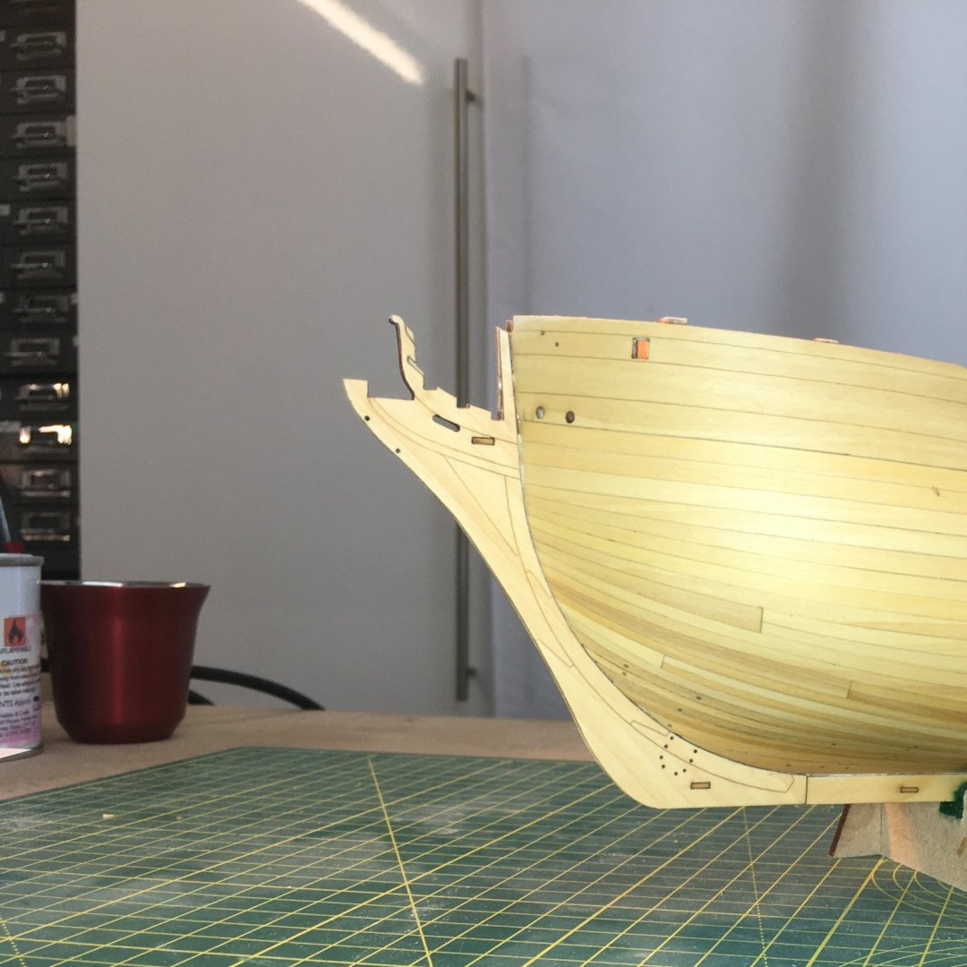

I gave up trying to find the errant piece in the black hole that is my workshop and decided to make a replacement from a piece of scrap pear. This is where Chris's scale plans showing every component are particularly handy, as I was able to photocopy the part and stick it to the wood for shaping. Here it is approaching the final shape:
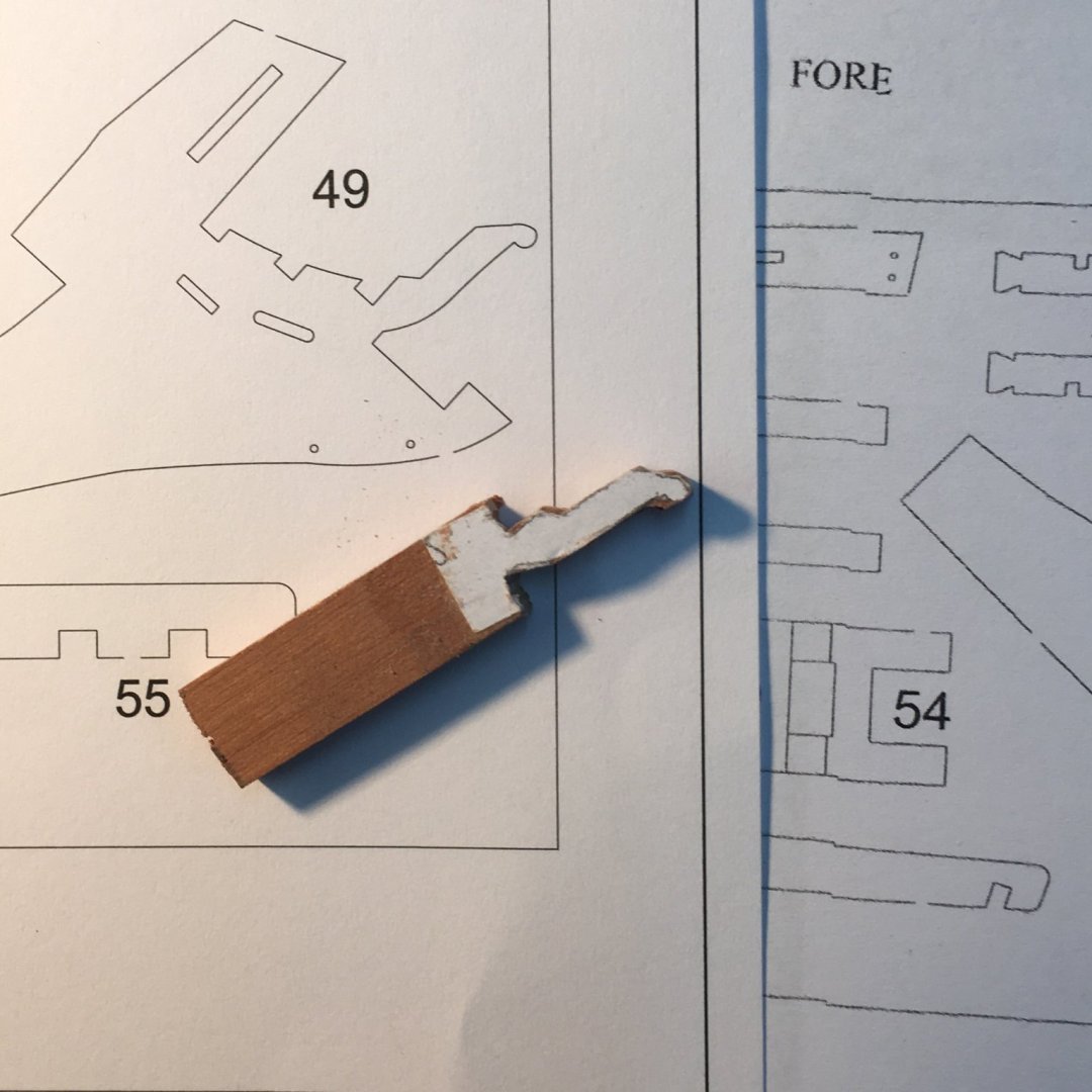
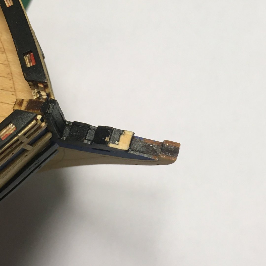
I departed slightly from the original model which consists of three layers - a 3mm wood core sandwiched between 1mm veneers. The latter are a slightly different shape to the core, creating small cut-outs in the final shape (these are visible in the first photo above). I decided I would use a single 5mm thick piece based on the shape of the 3mm core, and wing it if and when I needed the cutouts. After trimming the broken section to provide a firm base I dry fitted the new piece along with the figurehead and upper cheek rails. More work needed!
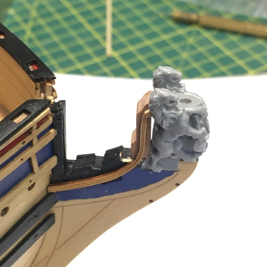
Important note for future builders
It was at this point I remembered a warning I read in @glennard2523 and @Rustyj's logs. The manual tells you to fit the cheek rails first, then the figurehead. Unfortunately the figurehead has a dovetail-type base which means it can only slide in to the prow from the side, which will be obstructed by the lower cheek rail. In fact the rail in the manual has been broken to fit the figurehead. Chris got the order right in the plans (Sheet 5) which describe and illustrate a very clear set of steps for constructing the bow area (@chris watton for info).
Anyway, to cut to the chase, here's the current state of play, with the repair in place along with the figurehead and cheek rails:

Now I'm looking forward to fitting more of this lovely photoetch decoration.
Derek
-
-
2 hours ago, Dr PR said:
For example, James Lees "The Masting and Rigging of English Ships of War" never says what he means by mast length
I agree he could have been more explicit. However in the first page of text he describes the taper of the fore and main masts from the heel to the head, so it's clear to me he's referring to the whole mast from then on. His work is based in large part on the instructions given to dockyards on the construction of masts and other spars, so when a mast length is given (and parts of the mast such as the head are specified in proportion to that length) that dimension must surely refer to the overall length.
-
Hi Dave
See my previous post. I definitely think you must be (understandably!) confusing the overall length of the main mast with the length of the first and largest component, also called the main mast. Also, the formula in use in Endeavour's day did not include the length - that was only used before 1719 and after 1793. The formula for the main mast (assuming Endeavour was refitted per RN standards) would have been beam X 2.28; main topmast = main mast X 0.6; main topgallant = main mast X 0.49.
-
2 hours ago, DaveBaxt said:
Derek I have had a look at James Lees book and pages 44 & 65 and it clearly shows that the mizzen cap fall short of the main mast top
Sorry Dave, I don't know how I let my eyes deceive me on that one. It's strange, because it makes the mizzen look very short especially compared to other models of the period (such as plate 61 of the Victory of 1737) where the mizzen cap looks almost on a level with the main top - which is what you'd expect from the proportion calculations I mentioned earlier.
16 hours ago, DaveBaxt said:When using the Caldercraft drawing They give the total length of 293 mm inlcuding the mast head. Now according to RC Andersons book The rigging of ships in the days of the sprit sail , the main mast is anywhere between 2 and 3 times the breadth of the ship .
The breadth of my model is 145mm
I think this is a separate issue. 293mm must be the overall length of the mast from the heel of the main mast to the truck of the main topgallant. When I cited the length of the main mast I was referring to the first of the three components of the mast, ie the main mast, main topmast and main topgallant. The main mast length is proportionate to the beam, the other two to the main mast. The overall height of the mast is these three added together minus the two overlaps.
Just seen your latest post - I'll stop this now for a quick response.
-
40 minutes ago, DaveBaxt said:
Thank you for that Derek and please forgive my ignorance but if those mast lengths include the section below the deck how cam we then work out the length of the main mast above the deck and then work out every thing else from that. Also when looking at James lees The Masting of Rigging of English ships of War . I thought it only covered rated ships. If the Endeavour is not rated, what is her classification.
Hi Dave
I don't believe Lees only covers rated ships. As a fully ship-rigged vessel refitted in a naval yard I'm reasonably confident her masts and rigging would have followed RN standards of the time. In fact, James Lees built and rigged his own model of Endeavour which is shown in several photos in the book - see especially Photos 64 & 65 which appear to confirm the respective sizes of the masts.
I'm not sure I understand your question about the length of the mast above the deck. Proportions such as the length of the masthead are worked out from the total length of the mast, not from the part above deck. Also, if all three masts are stepped into the keel then they all have the same baseline and any differences in their height will show up at their tops, regardless of how much of each mast shows above the deck.
Although a great resource, Lees' book can be difficult to wade through. Have you looked at Danny Vardas' spreadsheet? If not, it's a great resource available in the Articles Database on the forum, and will do all your calculations for you.
It sounds like you're on a similar journey to me. I didn't know any of this stuff a few years ago (and I'm sure there's a lot more I still don't know!) but it's great fun researching all these arcane facts. For me, it adds greatly to the pleasure of model shipbuilding, and I hope you're enjoying it too.
Derek
-
Hi Dave
Although she was originally built as a collier, the Earl of Pembroke, when she was bought by the Navy she was extensively modified for the expedition to the South Seas. I haven't read whether or not these mods included bringing the masts and rigging up to Navy standards but it seems likely, especially as the refit cost almost as much as the ship.
Anyway, that preamble is just to explain why I checked the Royal Navy Establishment in force at the time in James Lees The Masting & Rigging of English Ships of War. Given her beam, Endeavour's main mast would have been 70' 7" and her mizzen 60' 8" - about 10 foot difference. These are the overall lengths to where the masts are stepped in the hold. At the time, mastheads were 5" long for every yard the mast was long, which would make the main masthead 9' 9.5" - about 10 feet, confirming that the mizzen cap would have been level with the main top.
Derek
-
It may be an optical illusion, but looking back at your penultimate post I’m not sure the left hand window frame is the right way up. The frames should be very slightly wider at the base. All the others look OK but the LH* seems slightly off, at least in the photo.
* LH on the upright ship/RH in the photo


Duchess of Kingston by Delf - FINISHED - Vanguard Models - 1:64 - Boxwood version
in - Kit build logs for subjects built from 1751 - 1800
Posted
Thanks David, kind of you to say so. I'm enjoying watching our models progress in tandem.
I just think empty widow frames look wrong - nearly as bad as poorly applied glazing! I've struggled for a while to get it right, but the film I'm using at the moment gives good results if used carefully. My next job is making a replacement for the blasted plume on that figurehead.
Best wishes
Derek