


DelF
-
Posts
1,409 -
Joined
-
Last visited
Content Type
Profiles
Forums
Gallery
Events
Posts posted by DelF
-
-
Thanks David, much appreciated, although having just caught up with your Duchess log I think you're being unduly modest!
13 hours ago, desalgu said:I think I'm going to have to invest in some tools. Between table saw, sanding disk, lathe, milling machine, and perhaps something else I haven't thought of, what do you end up using the most? in other words, what would you buy first?
Machine tools can certainly help make jobs easier and quicker but careful use of hand tools can usually achieve the same end result and often with at least as much satisfaction. That mast head in your last post looks absolutely fine to me. Having said that, I love tools and asking a tool-o-holic like me which is my favorite is like asking me to name my favorite child*. Each has it's place, and most can be used for other jobs around the house. I've used the Byrnes saw to make picture frames and the larger mill and lathe to make plumbing parts that I couldn't find in the shops (always good selling points when trying to persuade the holder of the purse strings that I need another new 'toy'!).
(* Janet, but don't tell the other two)**
A good table saw is indispensable if you want to cut your own timber and the Byrnes is certainly the class leader. However I still hang on to my old Preac for really fine jobs. Sadly the Preac company is now defunct, but if you ever see one on the second hand market I'd snap it up if I were you. Anyway, a good table saw would have to be the first serious purchase for me (I'm not counting Dremel-type drill tools as they're relatively modestly priced and I assume we're talking significant investments?).
However the one tool I'd probably shed the most tears over if you took it away from me would be the Proxxon micro mill, purely because it has allowed me to tackle jobs I simply couldn't do before and has thereby greatly enhanced my enjoyment of the hobby. This was especially true when I built models by firms other than Vanguard and Syren and had to remake lots of out-of-scale and inaccurate parts. Just to give one example, kit ladders usually look far too chunky to me. The micro mill allowed me to make my own, being accurate enough to cut a series of precisely spaced slots 0.5mm wide and 0.5mm deep in 1.0mm thick timber to fit the steps. If you look round the site you'll find lots of examples of people putting the mill to good use.
Of course these are just my views - I expect other people would have different choices. The best advice I can give is don't just buy a tool because it seems like a good idea; wait until you've got a real need for a particular machine then do your research and go for the best you can afford based on that research. For example I didn't go for a wood lathe until I decided to make my own masts and yards from square stock and wanted to be able to shape them more quickly and accurately.
Hope this helps.
Derek
** Janet is a pseudonym 😬
- Ryland Craze and Thukydides
-
 2
2
-
-
Coming along very nicely David. I agree with your comments about ships' boats - not my favourite part of the build either.
On 5/7/2022 at 1:49 AM, TBlack said:Vanguard (Chris) now sells a hull, completely formed, with ribs
I'm tempted to go with Tom's suggestion when I get around to unboxing Sphinx.
On ratlines, I think the idea is that white thread is easier to see. Having tried it once, I'm going back to black.
Nice mice, btw. I make mine on the lathe, but your results look just as good and probably involve much less messing around trying to get angles and such right.
Derek
-
More Strops
Thanks for the kind comments and likes - much appreciated.
I've tried to continue following full size practice in rigging the various blocks and deadeyes to the masts. I'll describe the method used in rigging a 3mm deadeye to the
foremain mast.Following the steps I described in my previous post I produced a served line 0.5mm in diameter and 40mm long, with spare serving line left at each end and cut on the diagonal just outside the served portion . The line needed to be long enough to form an eye at each end, seize the deadeye and wrap round the mast leaving a short gap between the eyes. The gap doesn't need to be too precise - just wide enough to allow a decent lashing between the eyes.
To form each eye I held the cut end in a loop with self-close tweezers while I wrapped the spare serving line round the join (I think I must have been stirring paint with those tweezers😬😞
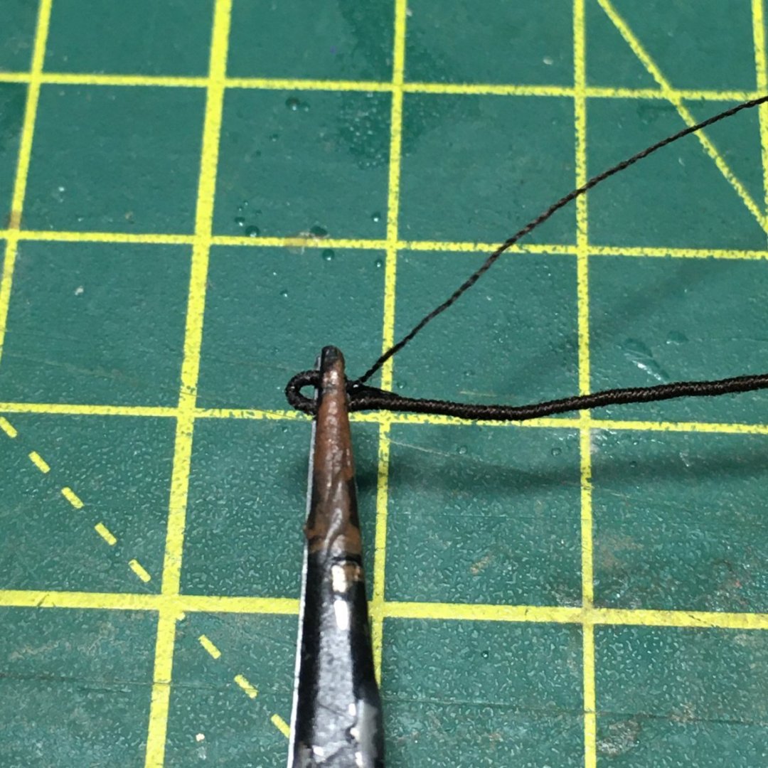
I tried gluing the join first but found the result too bulky. Instead, I wrapped the join first, finished the serving line with a half hitch round the served line, applied dilute PVA and trimmed when dry.
Here's the result with the deadeye seized in:
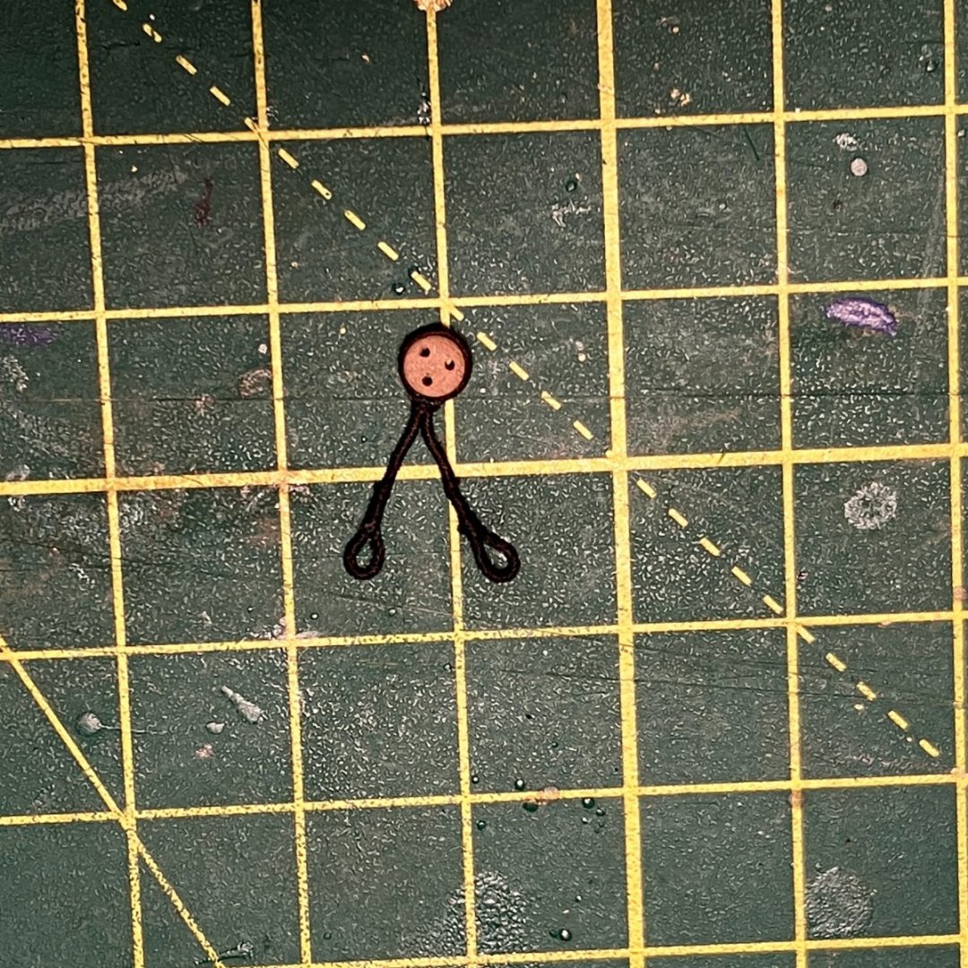
Previously I would have used 18/0 fly tying thread for the seizing, but I found that the Gutermann Mara #150 I used for serving was thin enough to do a decent (ie non-bulky) job. I'll probably still use the fly silk for smaller tackle.
I've also got the #150 thread in the shade I plan to use for running rigging (shade #854 for running rigging, #696 for standing) so I used that for the lashing. I started by tying one end to a loop...

...then with the strop in place round the mast I used a needle to thread the line back and forth between the eyes to create the lashing, finishing with a hitch round the centre:
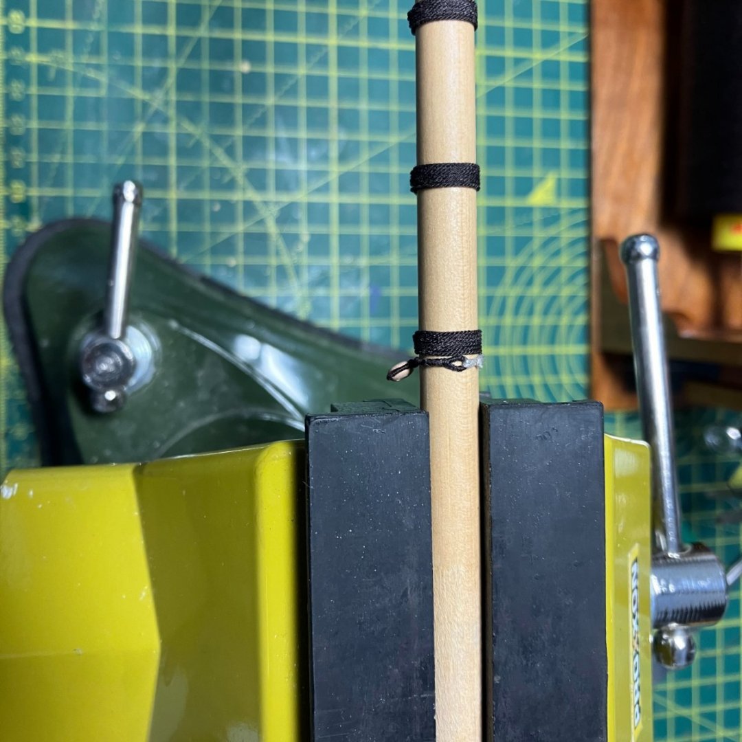
I've probably got the gap between the eyes a little wide in this example, but I still like the extra little detail.
Lots more blocks to attach to the yards next.
Derek
-
Rigging the Masts & Yards
Thanks guys, much appreciated.
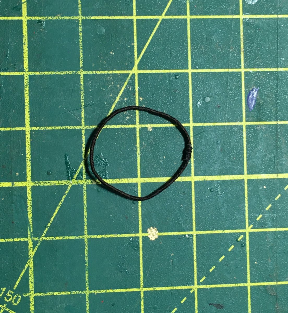
On my last model I found rigging the bowsprit quite challenging, especially the part where four deadeyes had to be seized into a ring. Here's how I tackled it on Speedy. This time round I decided to try a different approach, making a strop from a circle of served line into which I seized the deadeyes. I worked out the length of line I needed by adding together the circumferences of all the deadeyes and the bowsprit, plus 10mm to allow for overlap and seizings. To my surprise this actually worked out about right!
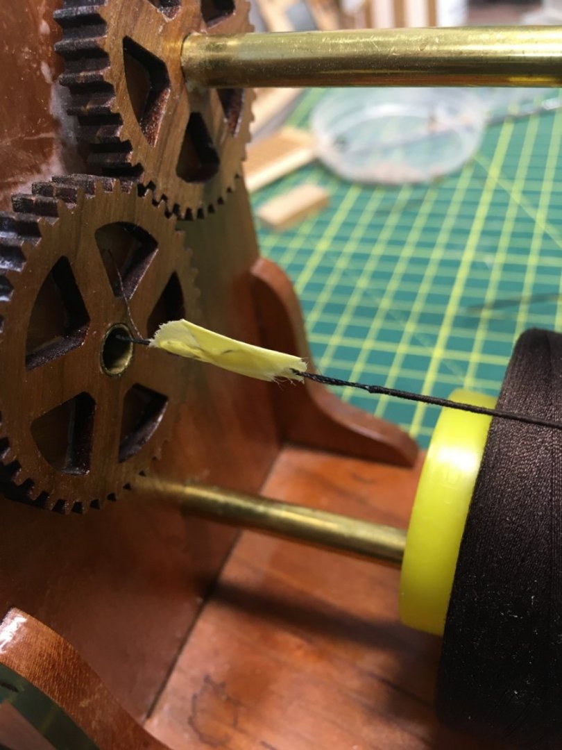
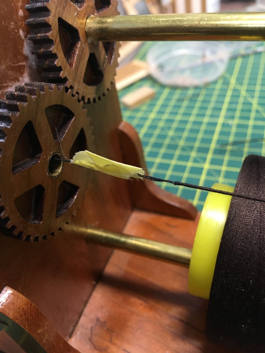
As the line would be served I used some spare thread from a kit, while for the serving line I used Gutermann Mara #150 in dark brown. #150 is the finest thread I've got, apart from fly tying thread. I've not measured it precisely, but I doubt it's more than 0.1mm. With the kit thread it produced 0.5mm served line. Here's the Syren Serv-o-matic set up with a fine needle starting the serving line off:
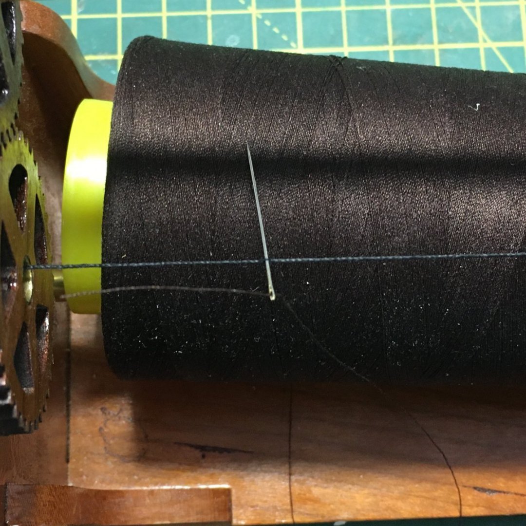
Not shown on the photo, I spread dilute PVA on the first few millimeters of line before serving it, just to prevent any tendency for the serving to unravel. I wanted to leave plenty of spare serving line, so to prevent it tangling up as the machine span round I taped the excess out of the way:
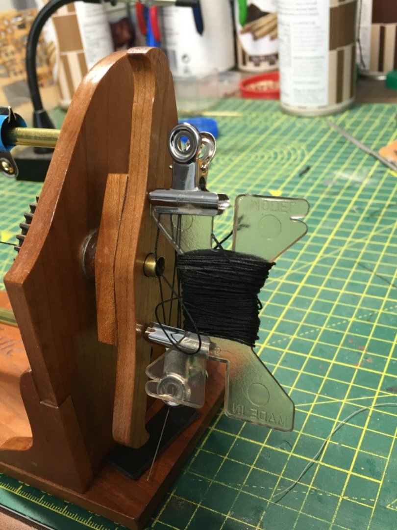
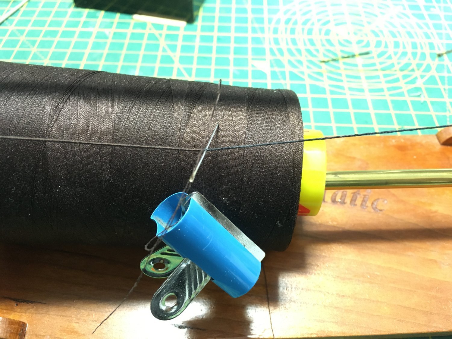
To save having to cut long new lengths of thread for each strop I clipped the thread holder to the handle, meaning I was always dealing with a single complete line and minimising waste:
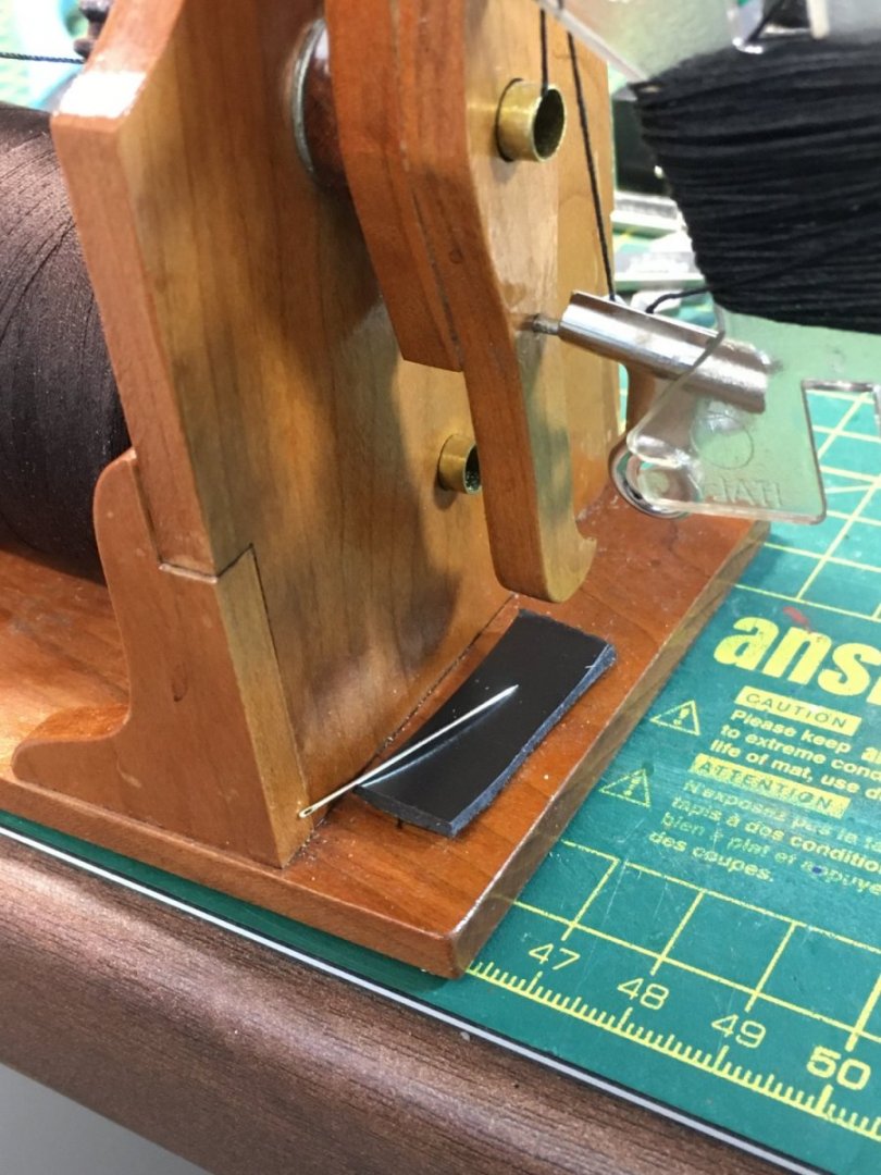
I'm always losing stuff in the workshop, so cut down on the frustration I try to keep tools where they're needed, as far as possible. So on the Serv-o-matic machine I've stuck a magnetic strip to hold the fine needle I only use for serving:
When I got near the final served length I smeared dilute PVA on the last few mills then threaded the needle through again, with a clip on the serving line to stop it unravelling:

When dried I made diagonal cuts at both ends, just outside the served portion, glued the cut ends together to form a circle, wrapped the spare serving line round the join, then finished with more dilute PVA before trimming:
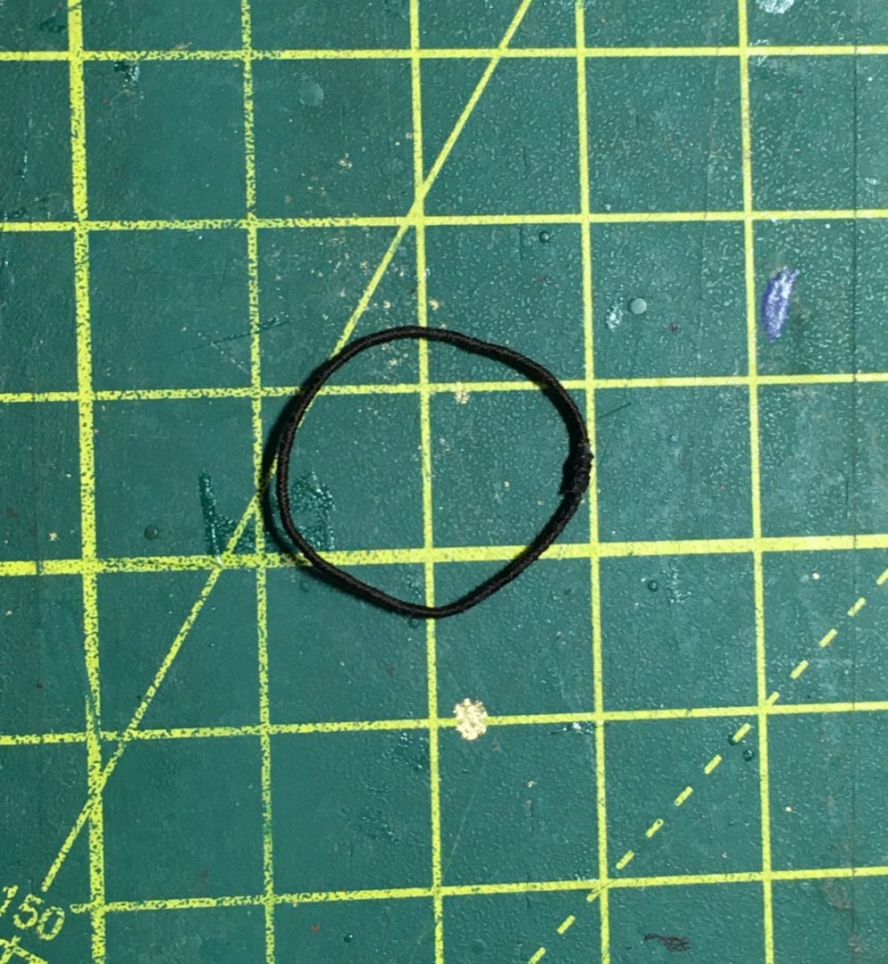
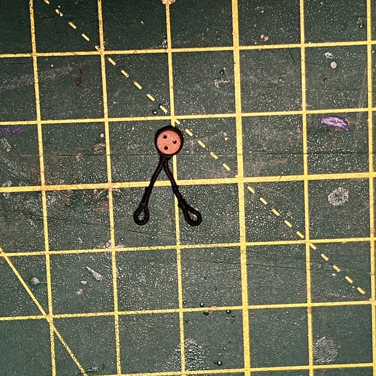
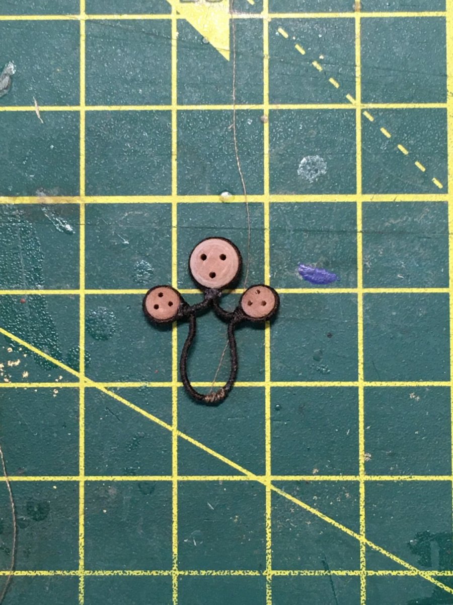
I felt the result was a bit chunky, so on my next attempt I trimmed the serving line right back then used fly tying thread to reinforce the join. Here's the strop with the first three deadeyes seized in:
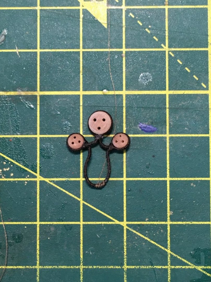
On reflection I could have used black fly tying thread as the brown is too light, but the join will not show as it will be hidden under the bowsprit. With 3 deadeyes in position I slipped the strop over the bowsprit and into its final position before seizing in the final 3mm deadeye:

I'll tackle strops on the masts next.
Derek
-
Masts & Yards
Some progress to report.
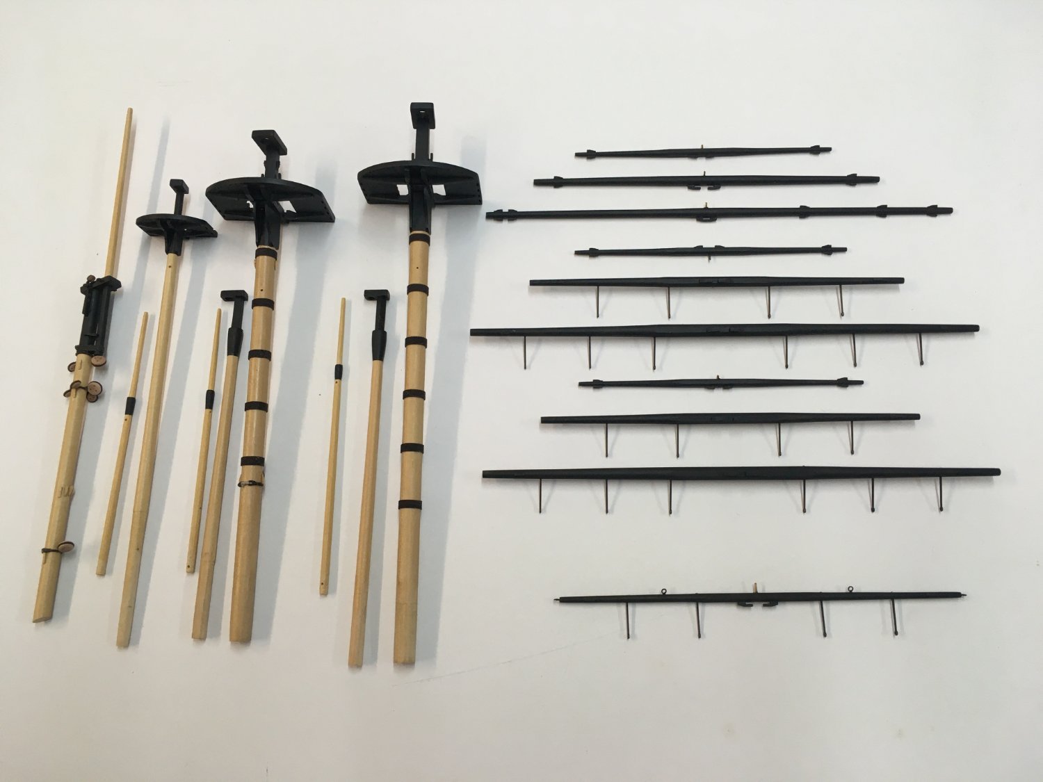
I've finished all the basic carpentry and ironwork on the masts and yards, and have started rigging the various blocks, lines and footropes. Following my usual practice I've made my own spars from boxwood, preferring the lighter wood to the kit material. Also, preparing the spars from square stock makes it easier to produce octagonal sections in the centre of the yards - with a couple of exceptions such as the mizzen yard and the cro'jack which are round throughout.
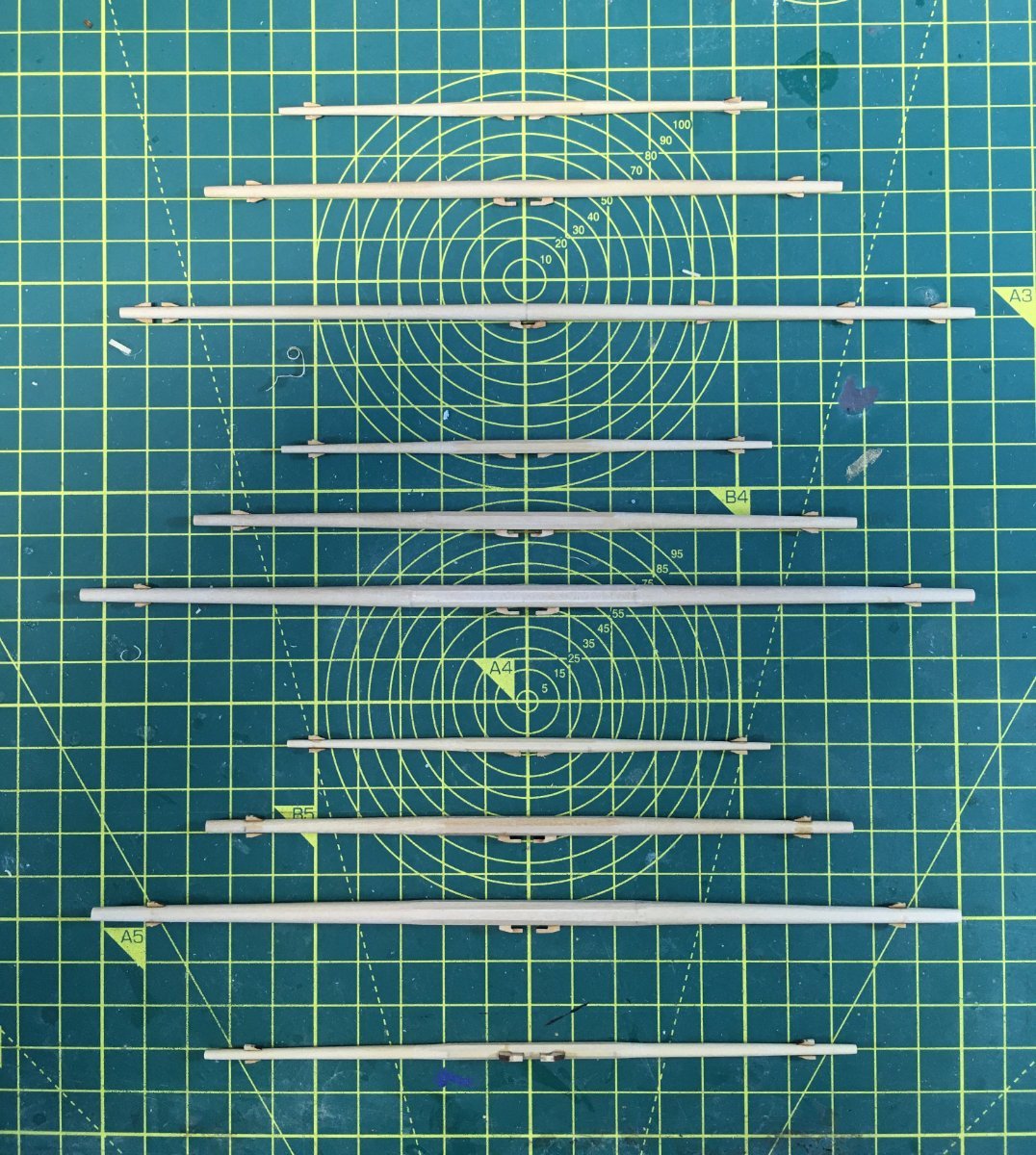
Here's the full set of yards before painting:
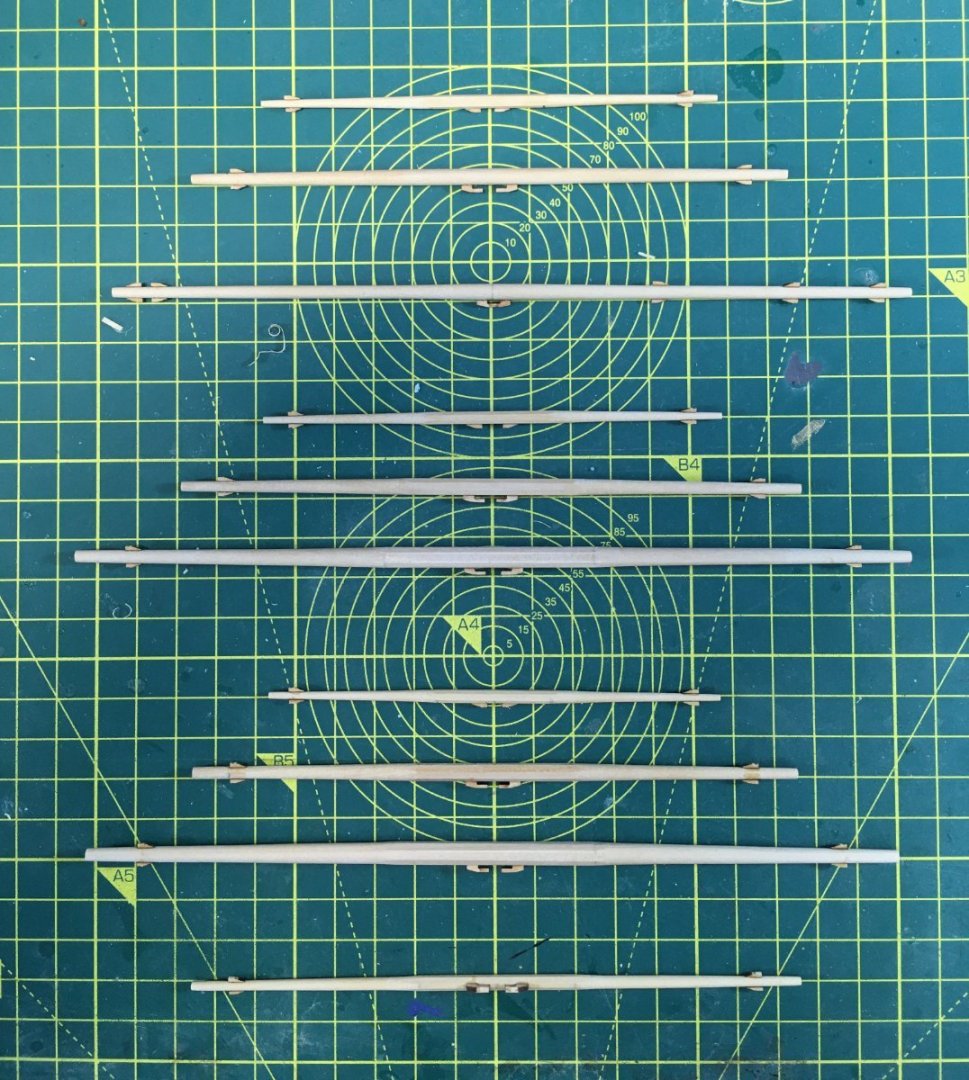
Care is required when making the mizzen yard (aka the lateen yard - the 3rd from the top of the photo) as the point where it attaches to the mizzen mast is slightly off-centre. Only by a few millimetres and easily missed, but it makes a difference.
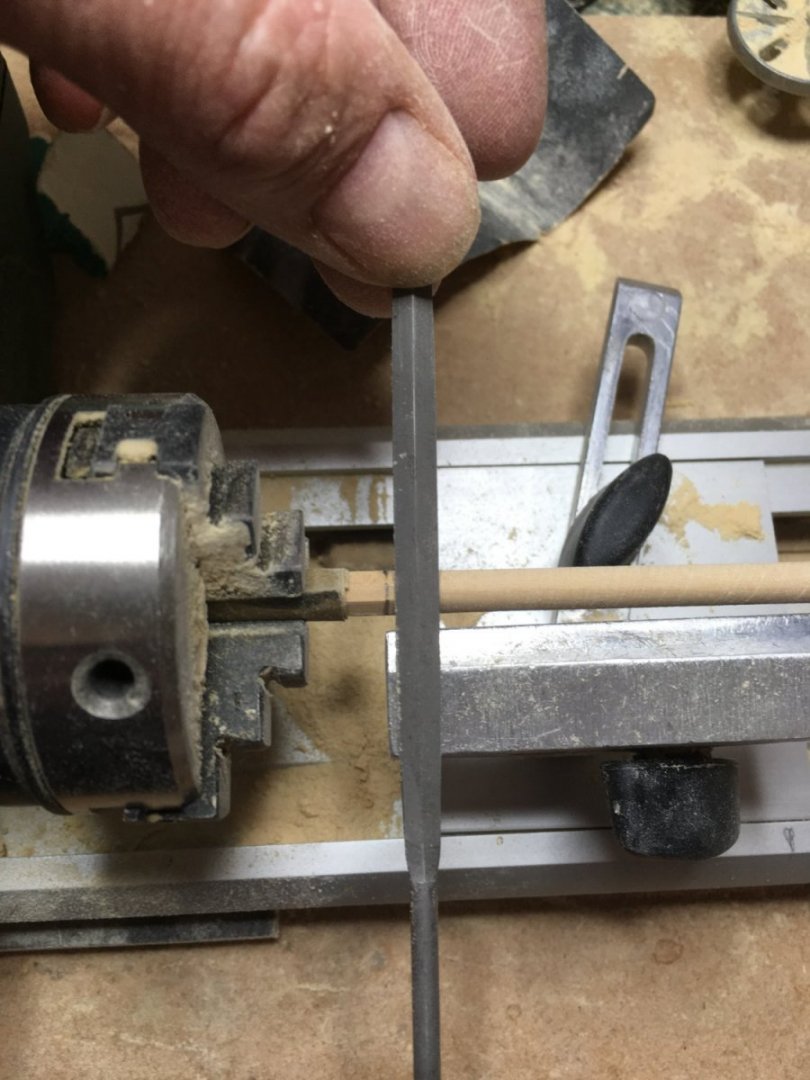
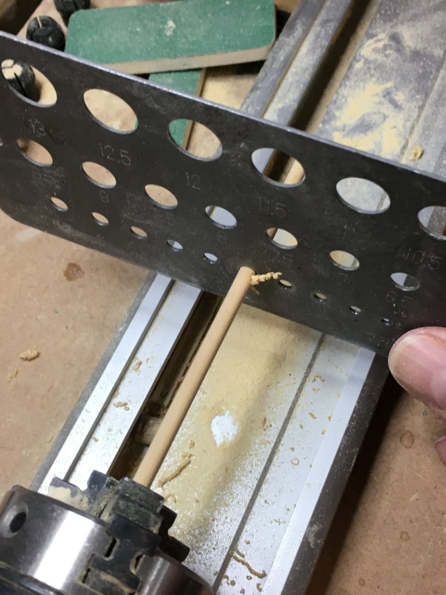
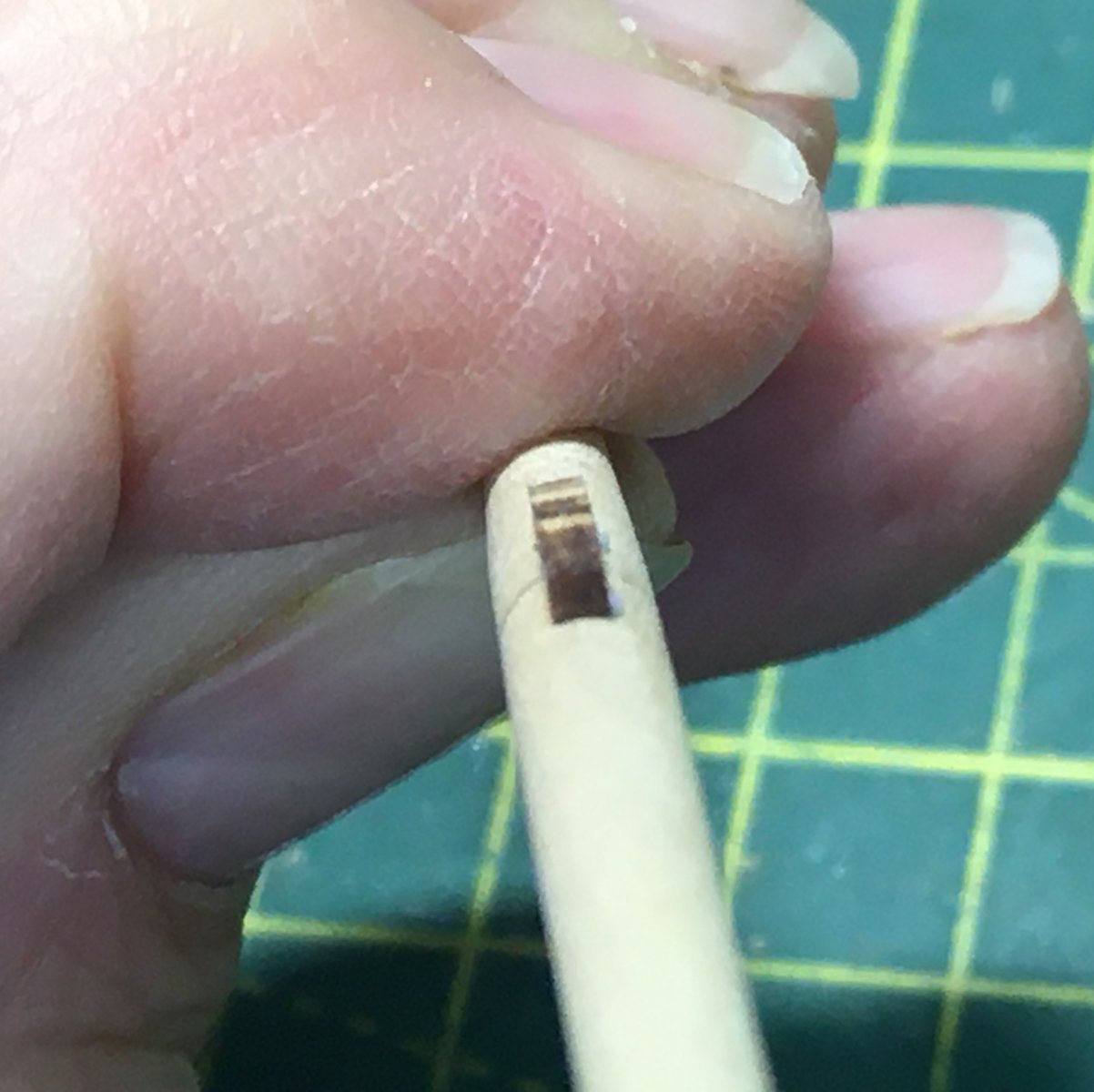
I covered spar making techniques in my Speedy log so I won't repeat all that here, but will just mention a couple of slight tweaks this time round. A quick way I found to trim the corners off the octagonal stock held in the Proxxon lathe was with an old drill gauge - crude but effective:

I made more effort to get a nice transition from the central octagonal section to the round ends. I found the best way to do this with a file held securely on the lathe rest:
The rest of the process is just the usual tapering with sandpaper and files.
When fitting cleats to the yards I usually struggle to get enough contact between the flat cleats and the round yards for the glue to grip. On the Duchess I tried using my finest rat tail file to make the undersides of the cleats concave to match the yards. Difficult at this scale but worth the effort:

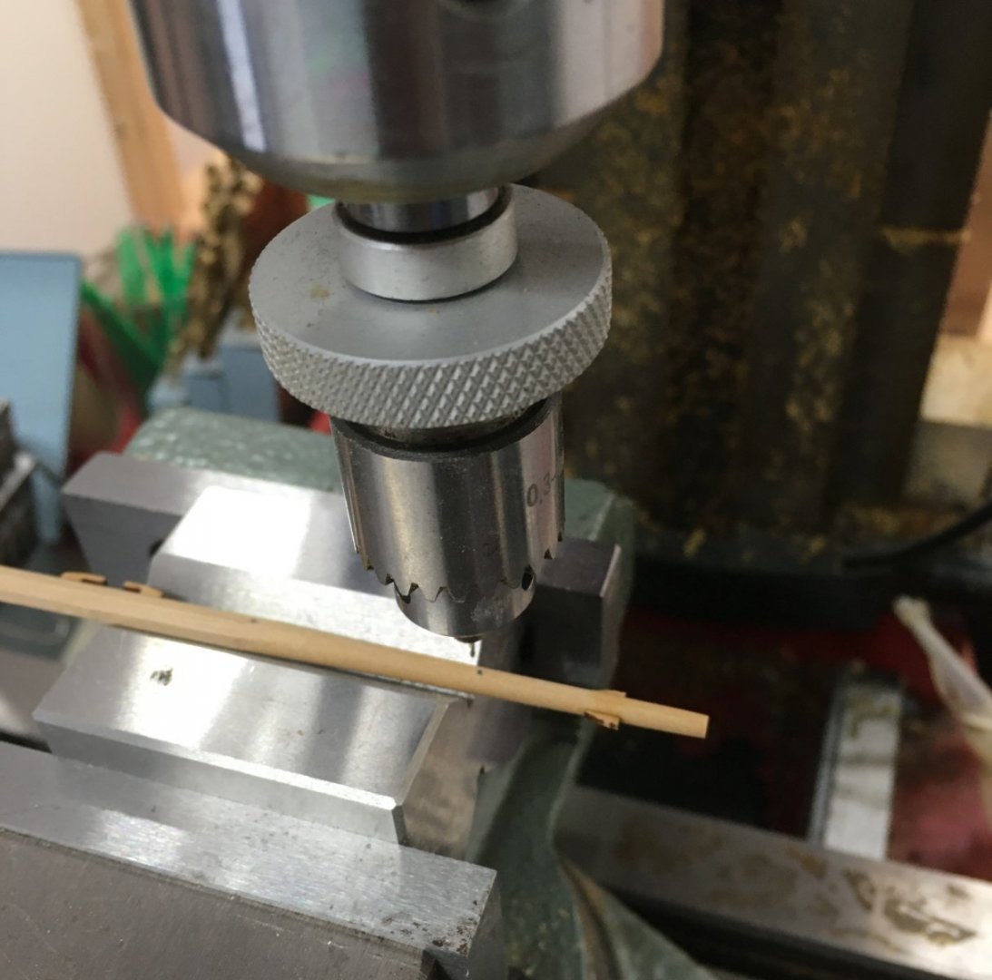
Various holes followed, using the micro drill attachment described in more detail here:
Then it was out with the spray gun:

I'll cover rigging the masts in the next post.
Derek
-
-
Wow. Just wow!
(That's me being speechless too)
- Dave_E and FrankWouts
-
2
-
-
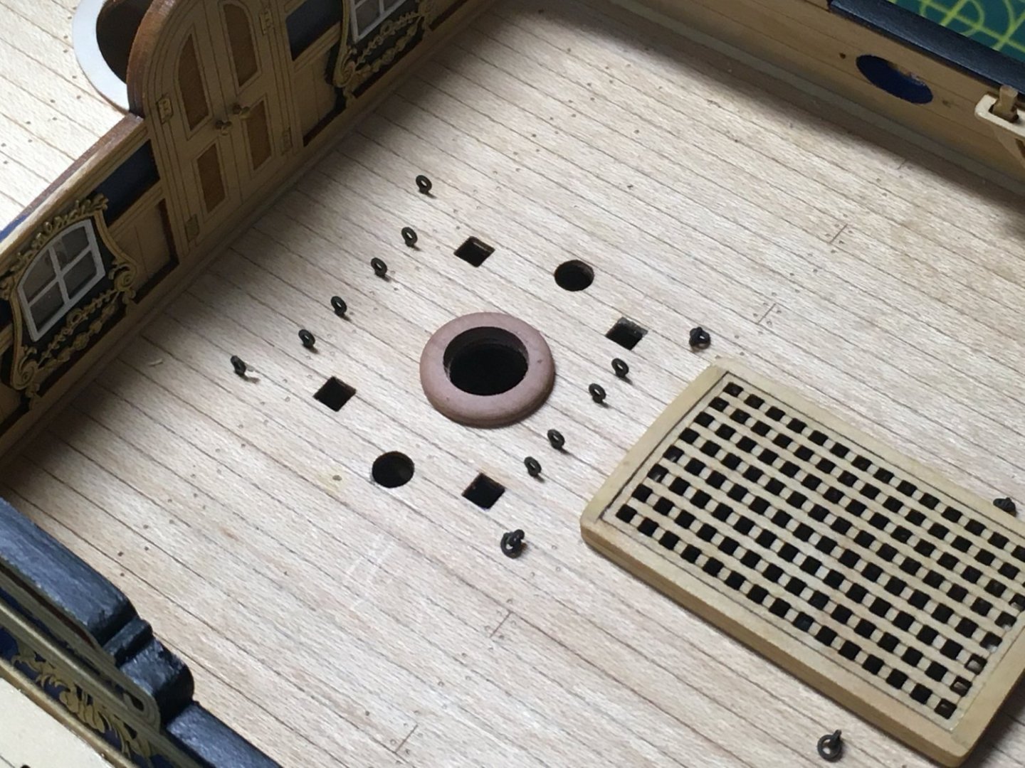
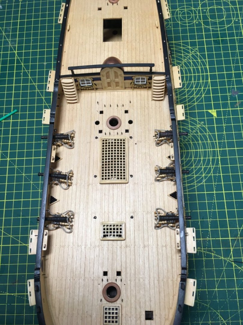
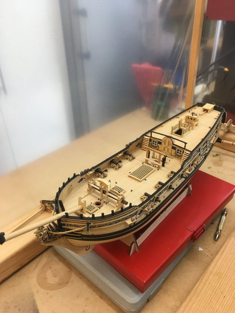
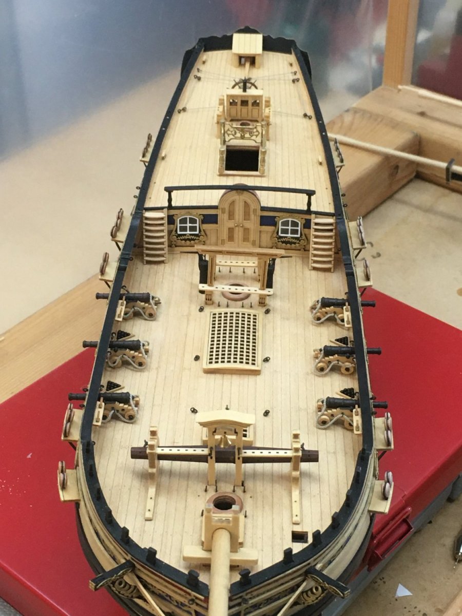
Very little to report I'm afraid, as I've been caught up in other projects. However I've finally got round to gluing the cannon and most of the deck furniture in place so I'm posting a few pictures of the current state of play. Mostly components I've already described - the one small exception being the spouts on the pumps, simply made from short lengths of brass tubing.

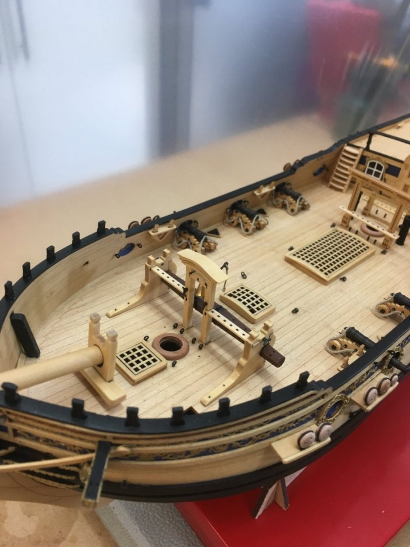
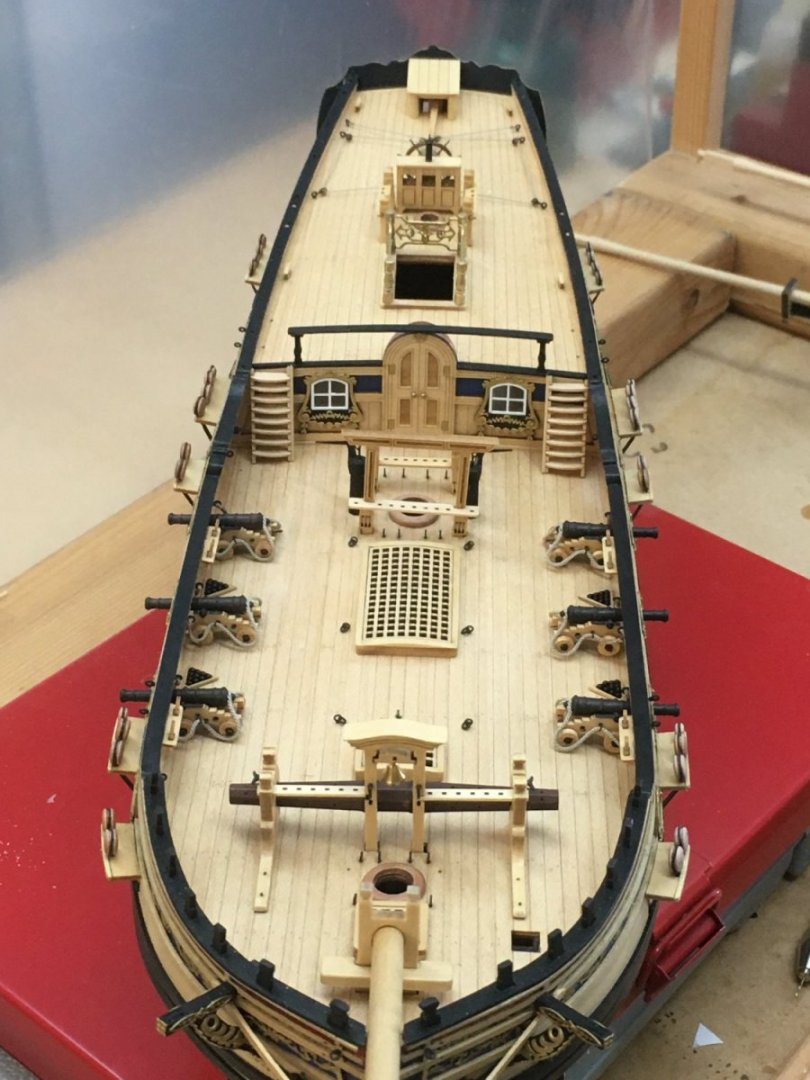
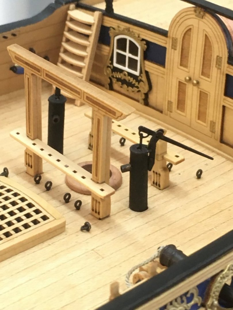
Amazing what you spot in photos but miss on the actual model! I've just noticed the main mast bitts are really wonky and will need fixing

The only other work I've done recently is on the spars, where I've made some of the masts and yards. I've had to put the Duchess in my dust cabinet to protect her while I file and sand the spars on the lathe, which makes lighting and photography a challenge. I'll record some of the detail in due course.
Derek
-
-
-
6 hours ago, Dave_E said:
How did you get those lower deadeyes into the chain plates? Is there a trick? I broke one of the rings and don’t have a clew how to open it up to put the deadeye in and then get it closed and looking good.
Here's a link to the method I used in my Speedy log. It doesn't matter if you haven't got the exact same tool as I used - anything smooth and tapered that you can push the chainplate over to expand it will do. I've also used a thin metal pen. A pair of fine nosed pliers helps to squeeze the ring shut.
Derek
-
Your serving looks really good David, and makes all the difference to the appearance of the shrouds.
Btw, thanks for referencing @Gerald Spargo's method for lashing futtock staves. Very helpful, and I've bookmarked it for future reference. I usually start with an over-length stave held against the shrouds in the quadhands, but this method looks much more practical. If others are interested, here's the link for convenience. Gerald's work is exceptional; I'd not come across his log before and have enjoyed reading through it.
Derek
- David Lester and Dave_E
-
2
-
-
4 hours ago, Rik Thistle said:
It is high speed
Richard's point about speed is an important one. The MF70 has a maximum spindle speed of 20,000 RPM, which is about eight times faster than my larger 'regular' mill. Small mills rotating at high speed produce very clean cuts which makes them ideal for miniature work like model ship building. Larger mills have their place, but I always turn to the Proxxon for the finest work.
Derek
- Ryland Craze, mtaylor, Canute and 1 other
-
4
-
+1 for the Proxxon MF70. Search on the forum and you'll find lots of examples of the work it can produce.
Derek
- DaveBaxt, mtaylor, Ryland Craze and 2 others
-
5
-
Stunning. Yet another skill I'm going to have to master!
- Blue Ensign and mtaylor
-
1
-
 1
1
-
Quarter deck rails, ladders, timberheads etc.
Thanks as always for the kind comments and likes.
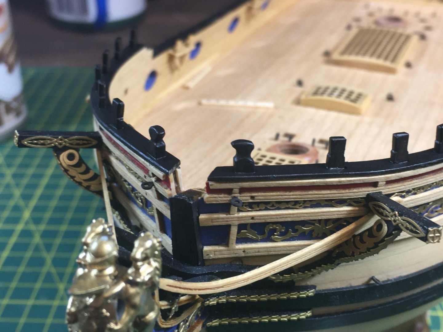
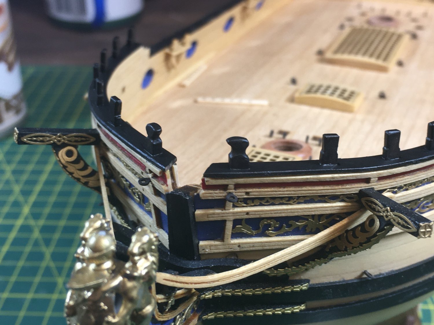
I'm still just pottering around the deck furniture and other fittings, with plenty of distractions keeping me out of the dockyard. Although most of the fittings are built I've been reluctant to fit them as I go along as they tend to get in the way and get damaged. However I'm getting to the stage where I'm having to put glue to wood. One of the first jobs was the forecastle timberheads - two large either side of the bowsprit and 12 smaller ones behind them. They needed a fair degree of sanding and filing to bring out their proper three dimensional shape. I also felt they looked better painted black rather than left natural:
Just visible in the photo above is the foremast base. The main mast base is clearer in the photo below:
For contrast with the mast and deck I decided to make my own mast bases from Swiss pear, using the method I described in another topic here.
I won't stick the bases down until I fit the masts.
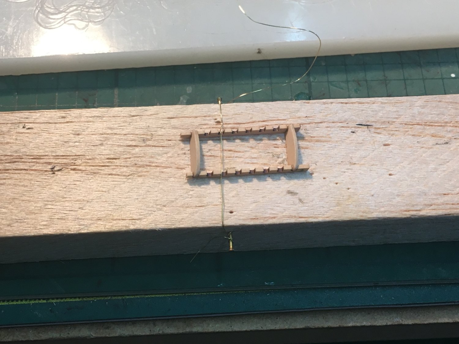
Next I turned to the two ladders leading to the quarterdeck. Apart from the inevitable char removal the only slightly tricky steps were remembering that the port and starboard ladders were different, and holding the fiddly pieces during gluing. I ended up holding the side rails down with a length of wire pinned to a block of balsa, gluing the top and bottom steps first then filling between:

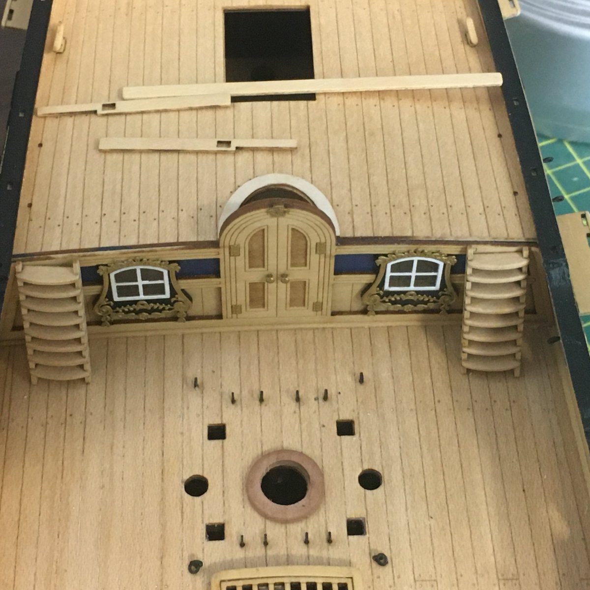
Here are the completed ladders being dry-fitted to check size and position:
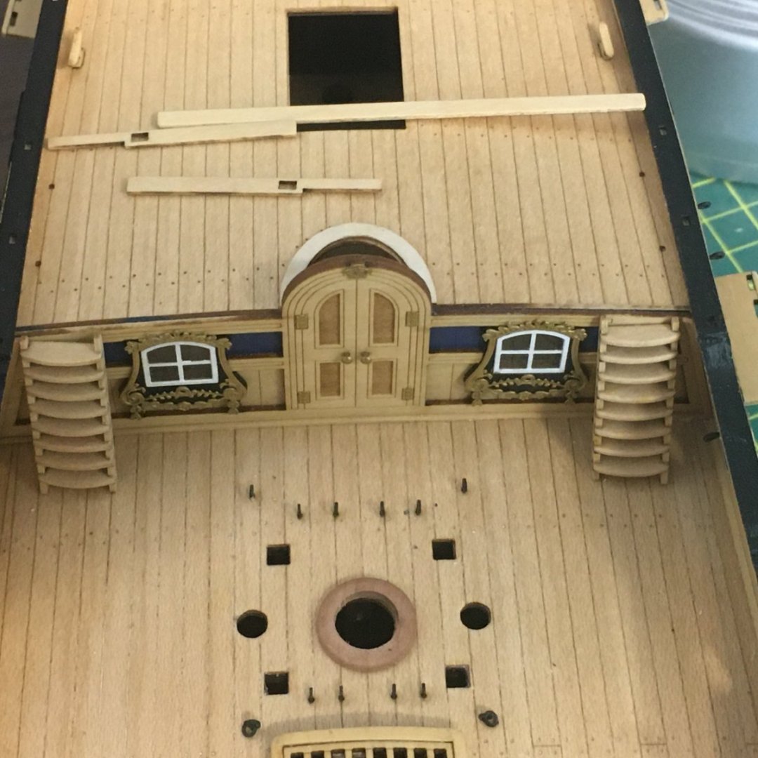
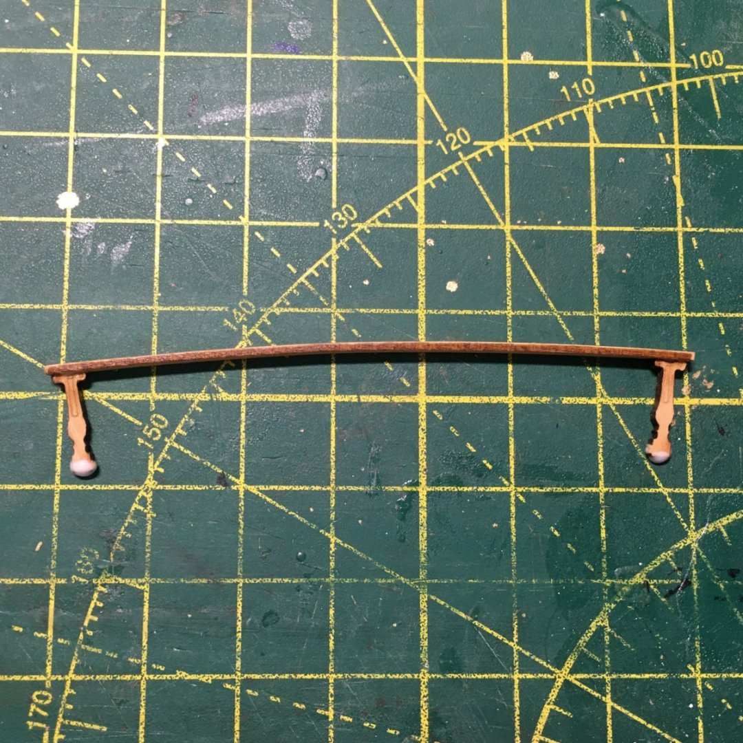
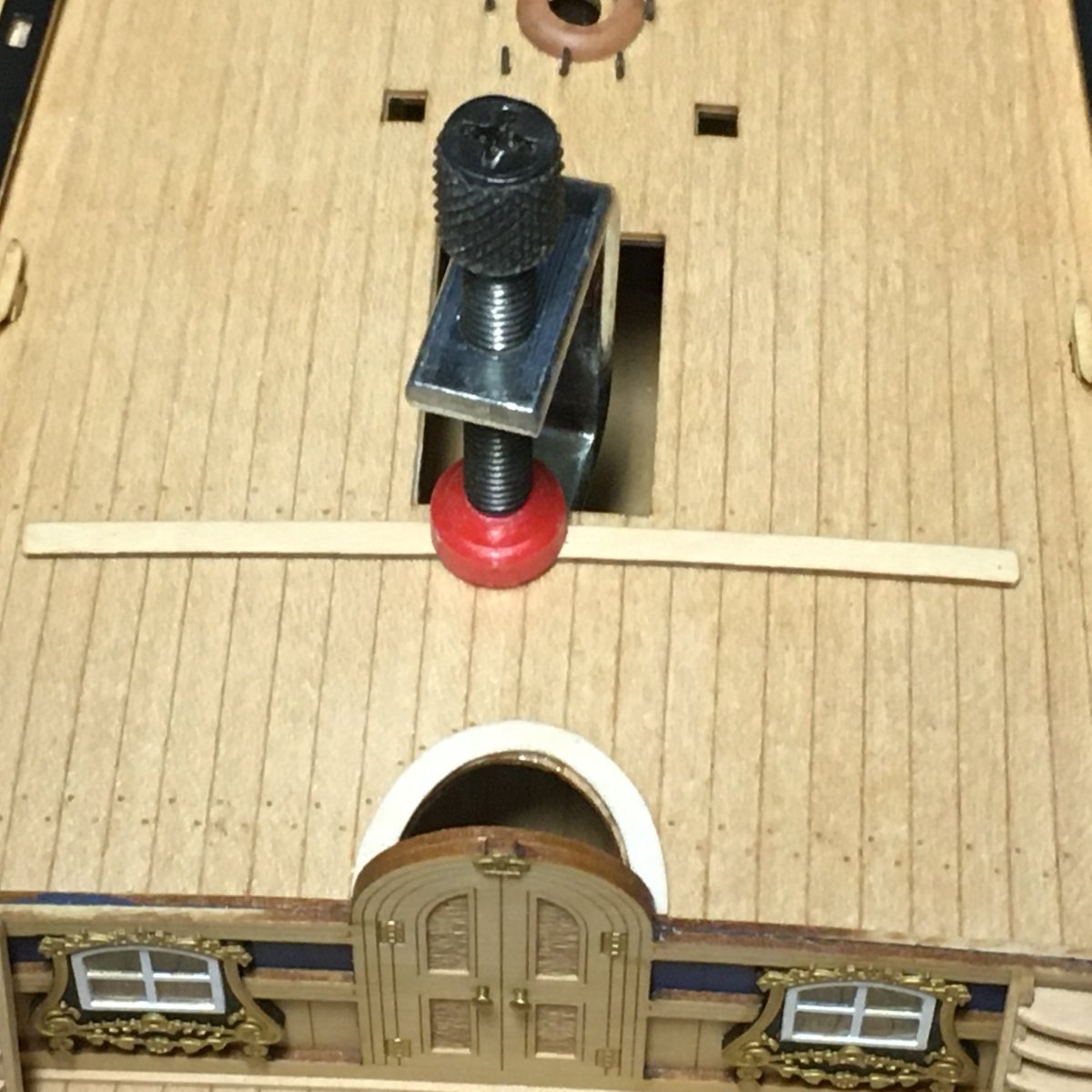
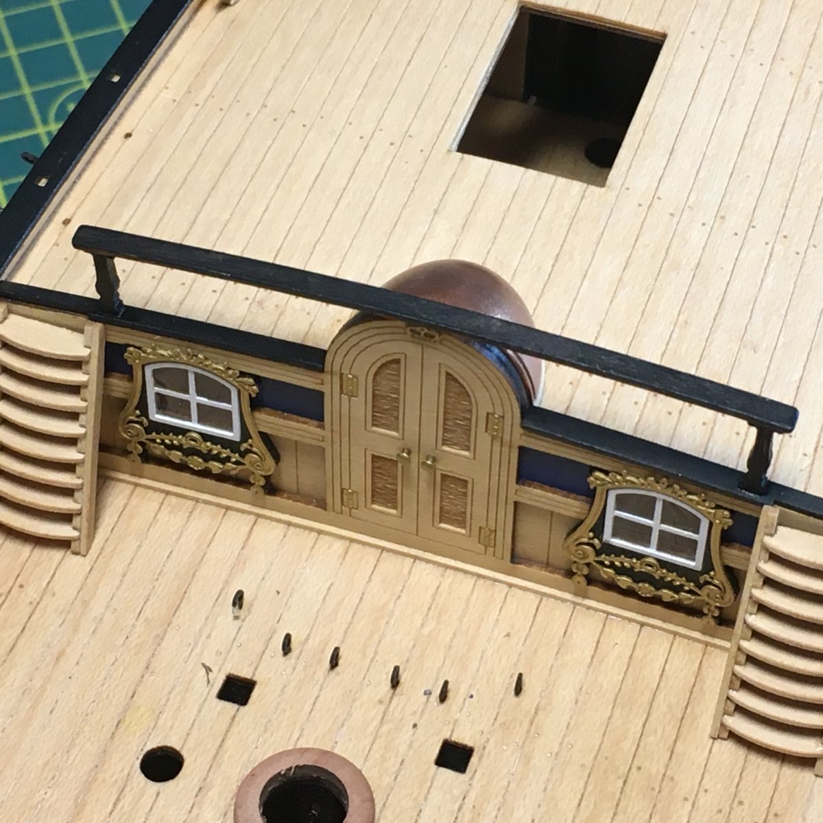
The components visible on the quarterdeck are the two boards that cover the front edge of the deck either side of the canopy, and the handrail. I bent the handrail with dry heat via a hot air gun over a curved tin can. However the result was too curved, so to get it to conform to the required shape I clamped it to the quarterdeck overnight:

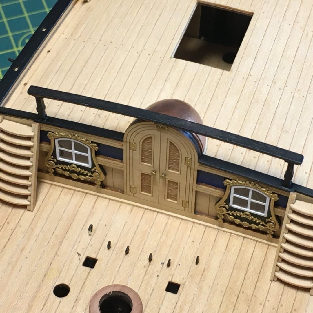
Next, I painted the covering boards black and glued them in place. I also painted the top edge of the door frame black to match, then glued the ballustrades to the handrail. Shallow cut-outs in the underside of the handrail made it easy to locate the uprights:
Here's the rail painted and in place along with the canopy which I painted copper:
Finally, I couldn't resist dry-fitting the guns:
When I fit them permanently I'll brush dilute matte acrylic medium on the breeching ropes to make them lie more naturally.
Derek
-
9 hours ago, glbarlow said:
Proxxon Pen sander
How do you get on with this tool - would you recommend it?
9 hours ago, glbarlow said:It’s looking more and more like a ship...
...a very beautiful ship!
Derek
- glbarlow and FrankWouts
-
2
-
Very well done, and well deserved!
- Ryland Craze and Jack12477
-
1
-
1
-
18 hours ago, desalgu said:
Looks like you added a little "iron" piece on the back of the cannons that I don't remember being in the kit.
The quoin, the little wooden wedge under the rear of the barrel, was indeed used to adjust the elevation. The quoin often had a handle at the rear to make it easier to push and pull in and out, which is what I tried to represent with a piece of wire. I believe the steps in the sides of the carriage also had a role to play, by providing pivot points at different levels for levers to move the barrels.
- bruce d and chris watton
-
2
-
-
17 minutes ago, Blue Ensign said:
B.E.
27/02/22
I know you work quickly but you've really got ahead of the rest of us today!
Brilliant and informative as always, regardless of the time travel.
Derek
- mtaylor, Blue Ensign and hollowneck
-
2
-
 1
1


Duchess of Kingston by Delf - FINISHED - Vanguard Models - 1:64 - Boxwood version
in - Kit build logs for subjects built from 1751 - 1800
Posted
A really good point Glenn. Kit supplied timber can vary considerably in thickness, even from the best companies. I try to plane planks down to an even size but it's a pain and I can see a good thicknesser being the best solution. How bad is the dust though?
Derek