


DelF
-
Posts
1,409 -
Joined
-
Last visited
Content Type
Profiles
Forums
Gallery
Events
Posts posted by DelF
-
-
Cannon #2
Thanks as always for the kind comments and likes.
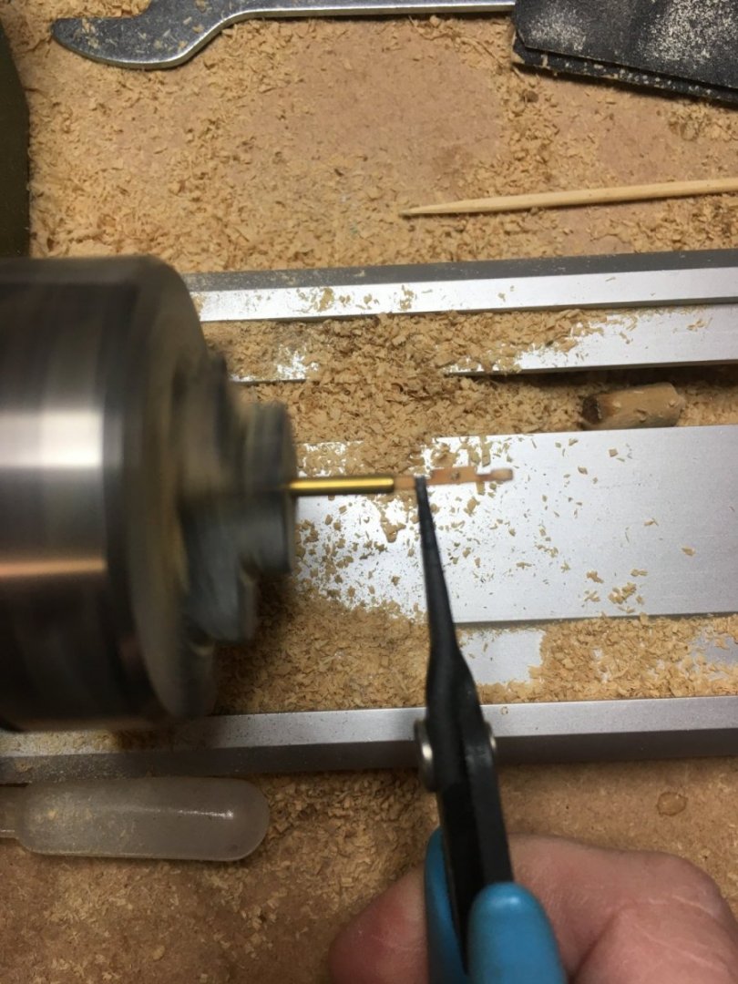
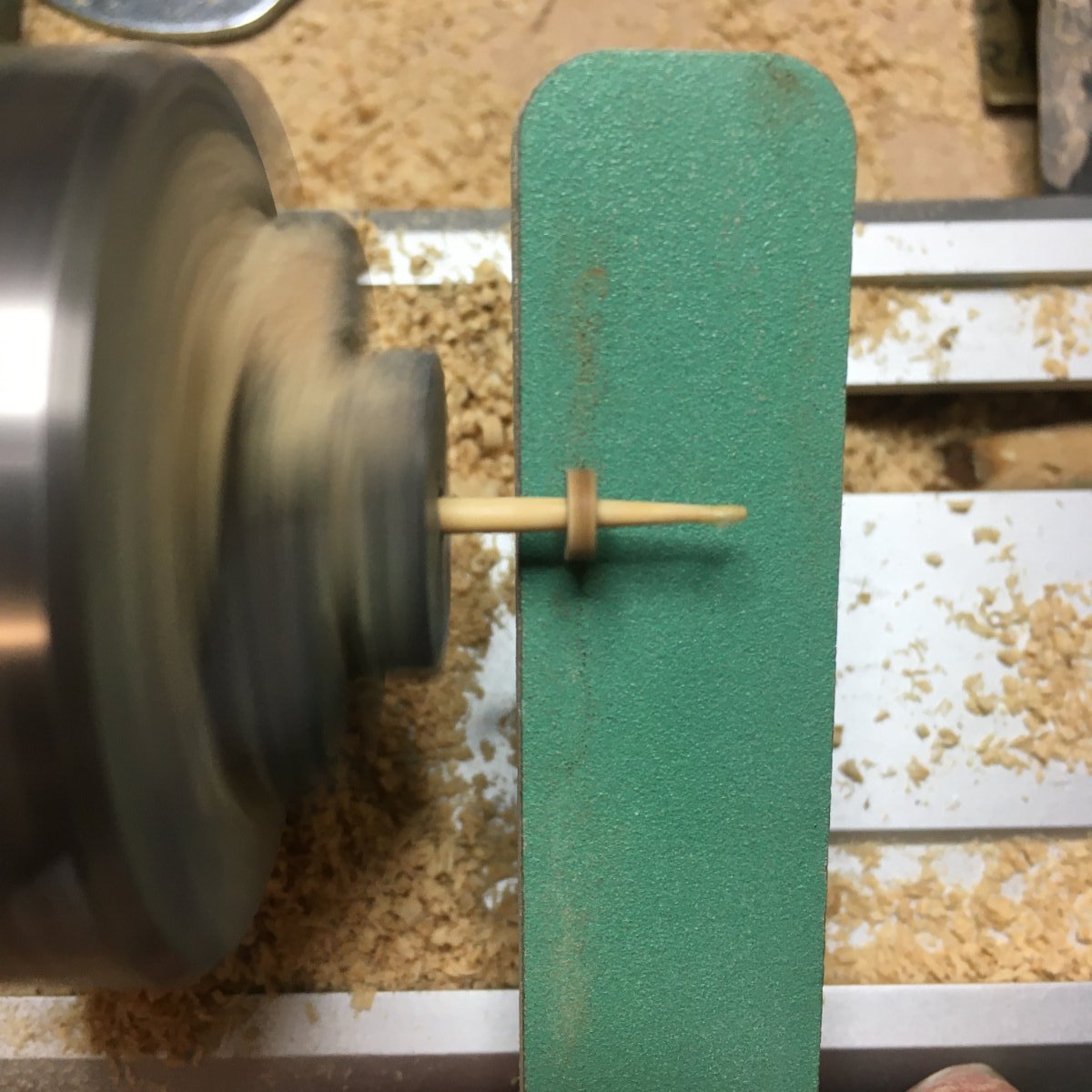
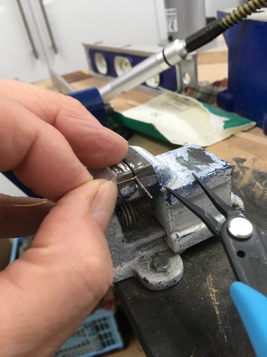
I've finished building the cannon, with just a couple of additional points to record. First, I found rounding off the axles by hand with sandpaper was a bit hit and miss so I decided I needed something a bit more accurate and repeatable. I used a short length of brass tube with a suitable internal diameter (I think it was 1/16") mounted in the lathe. First I filed the end from the outside to create a sharp edge then, holding an axle carefully with pliers and gently pressing against the spinning tube, the result was just the right amount of rounding:
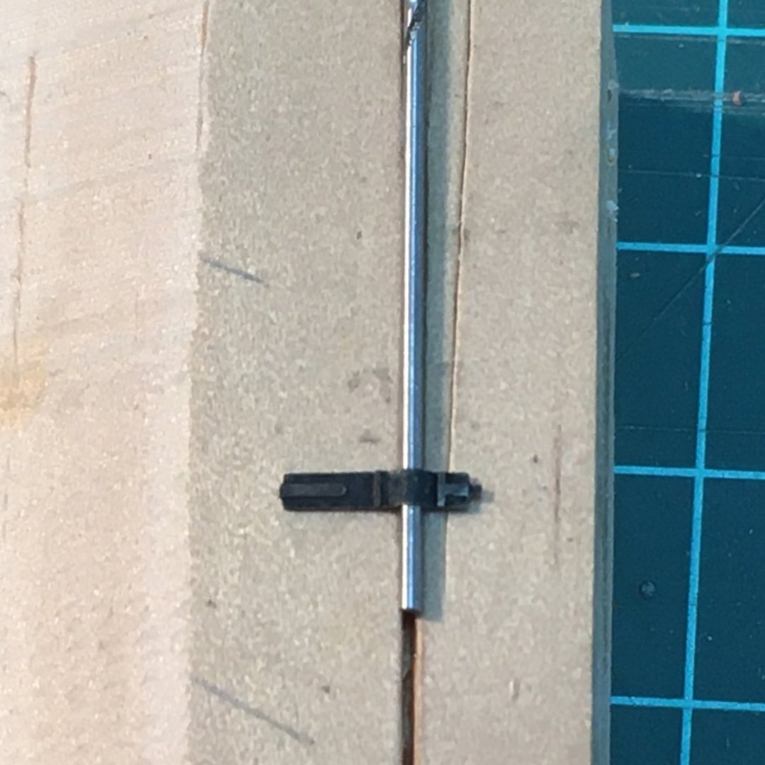
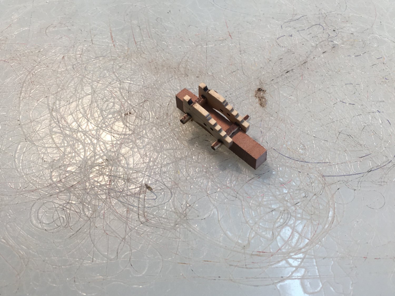
I also found gluing the components of the carriage tricky so I milled a couple of 1.5mm slots in a small piece of wood to make the job easier:

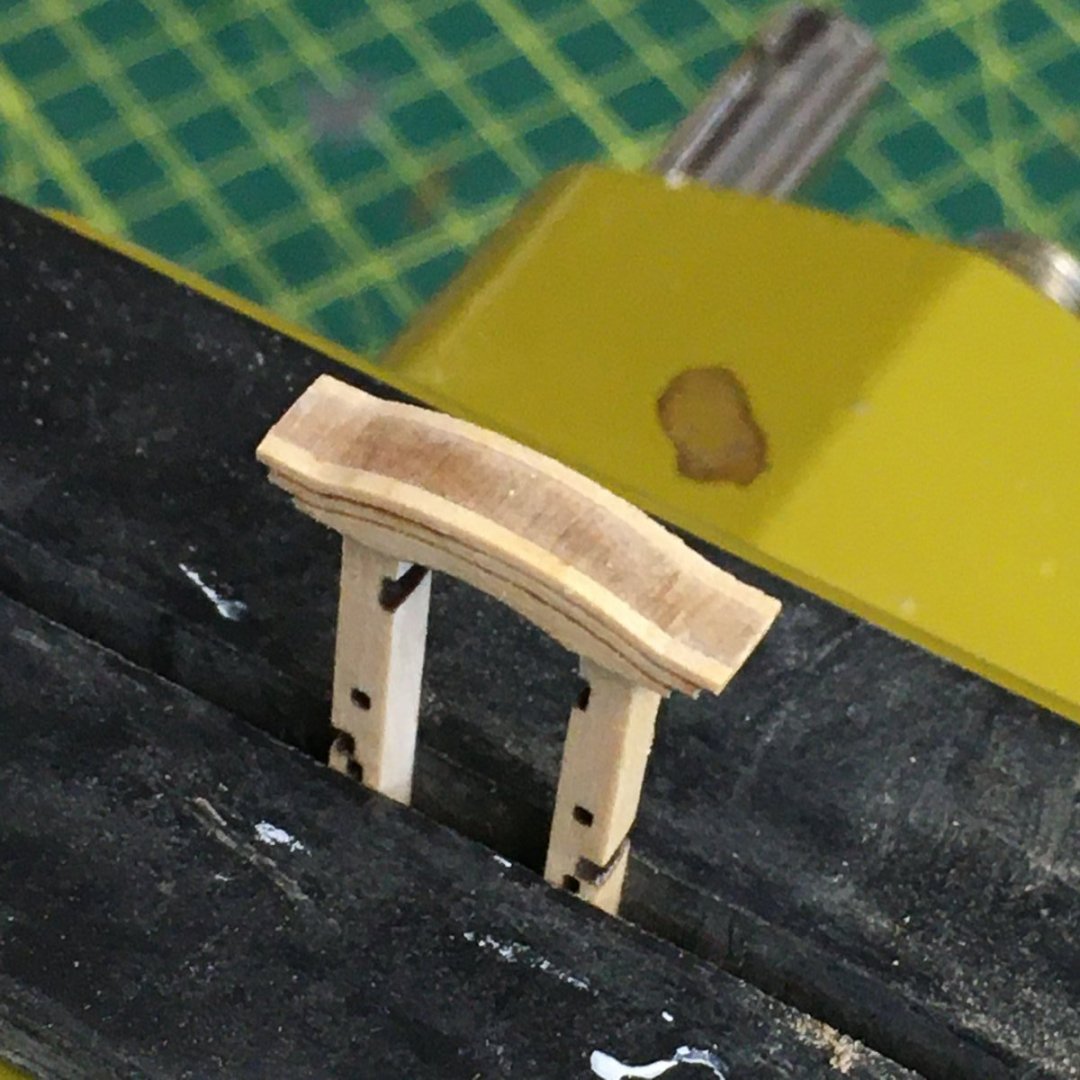
Next I dug out a little jig I'd made to shape the cap-squares for Speedy, just a groove half the depth of a drill bit the same diameter as the trunnions. A thumbnail either side and the cap-square is ready-shaped to fit.
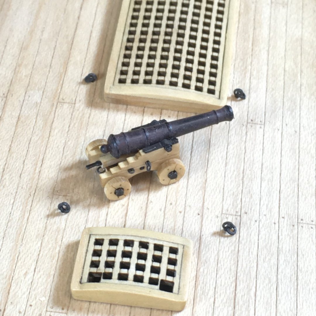
Here's the completed cannon:
Despite encouragement (?) from Mr Barlow (@glbarlow) I'm not going to fully rig the guns. I've done it once, for Speedy, and once is enough - a least for a while. I'll do the breechings though, as I think the guns will look bare without them.
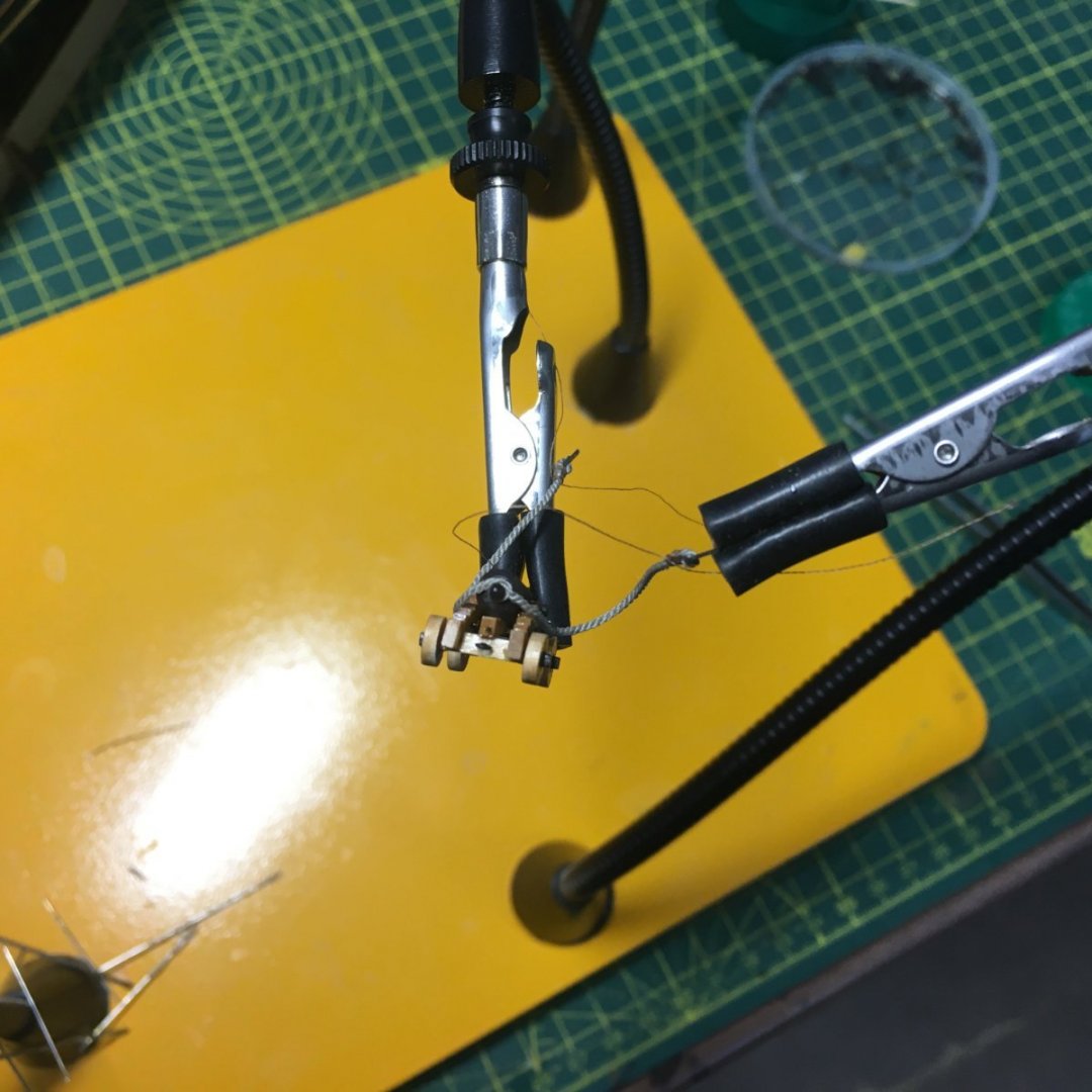
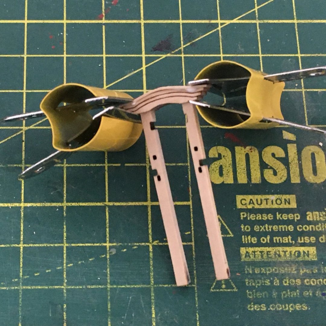
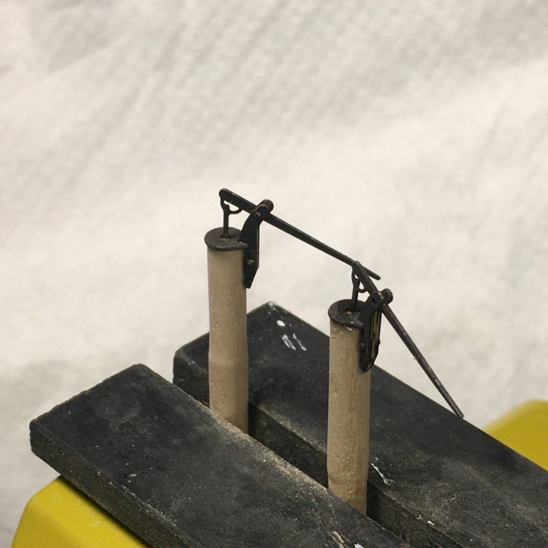
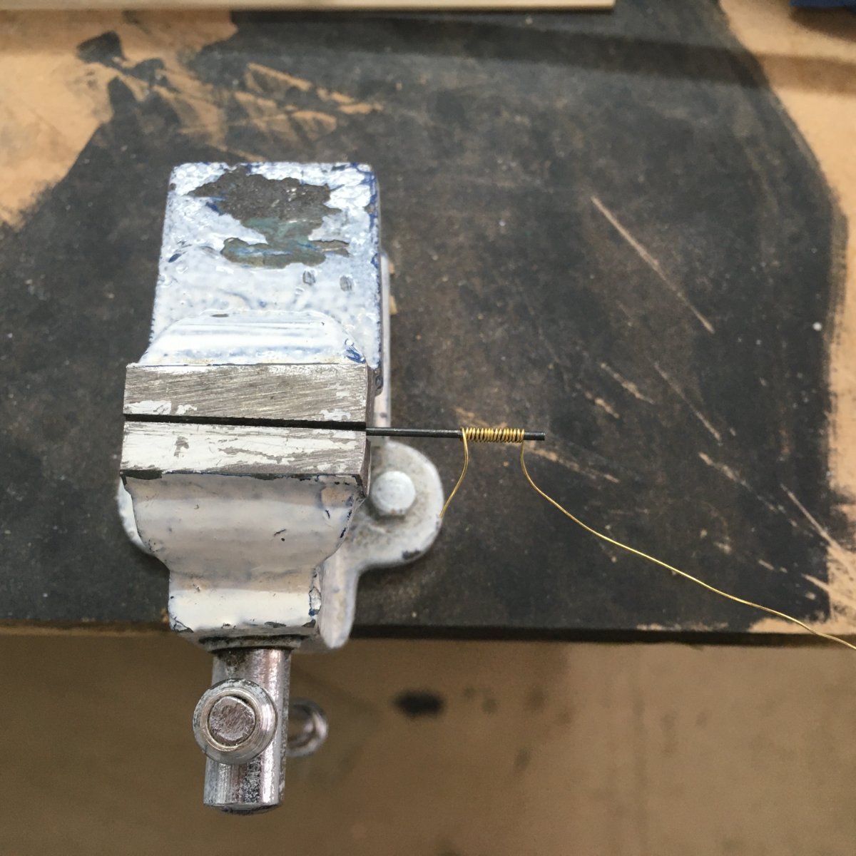
I've run up some 0.7 mm line on the Rope Rocket for the breech rope and made a start on the first couple of guns. According to Lavery in The Arming & Fitting of English Ships of War, breech ropes were typically three times the length of the barrel to allow for just the right amount of recoil. I'm making mine 85mm to allow a few mill for seizing. I'm doing the latter on the quadhands - here's a picture and for more information I've described the process in more detail in my Speedy log here.
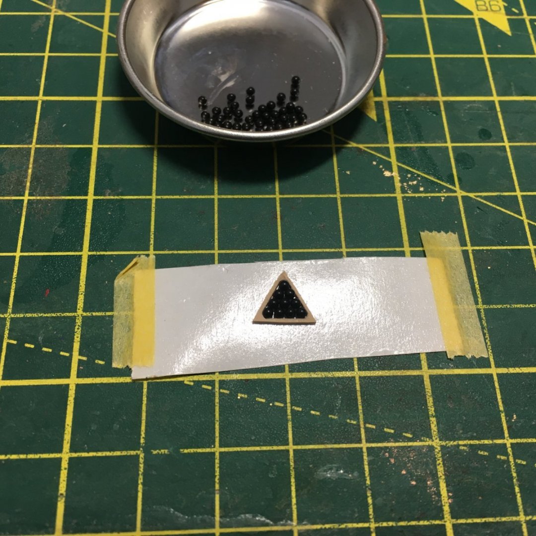
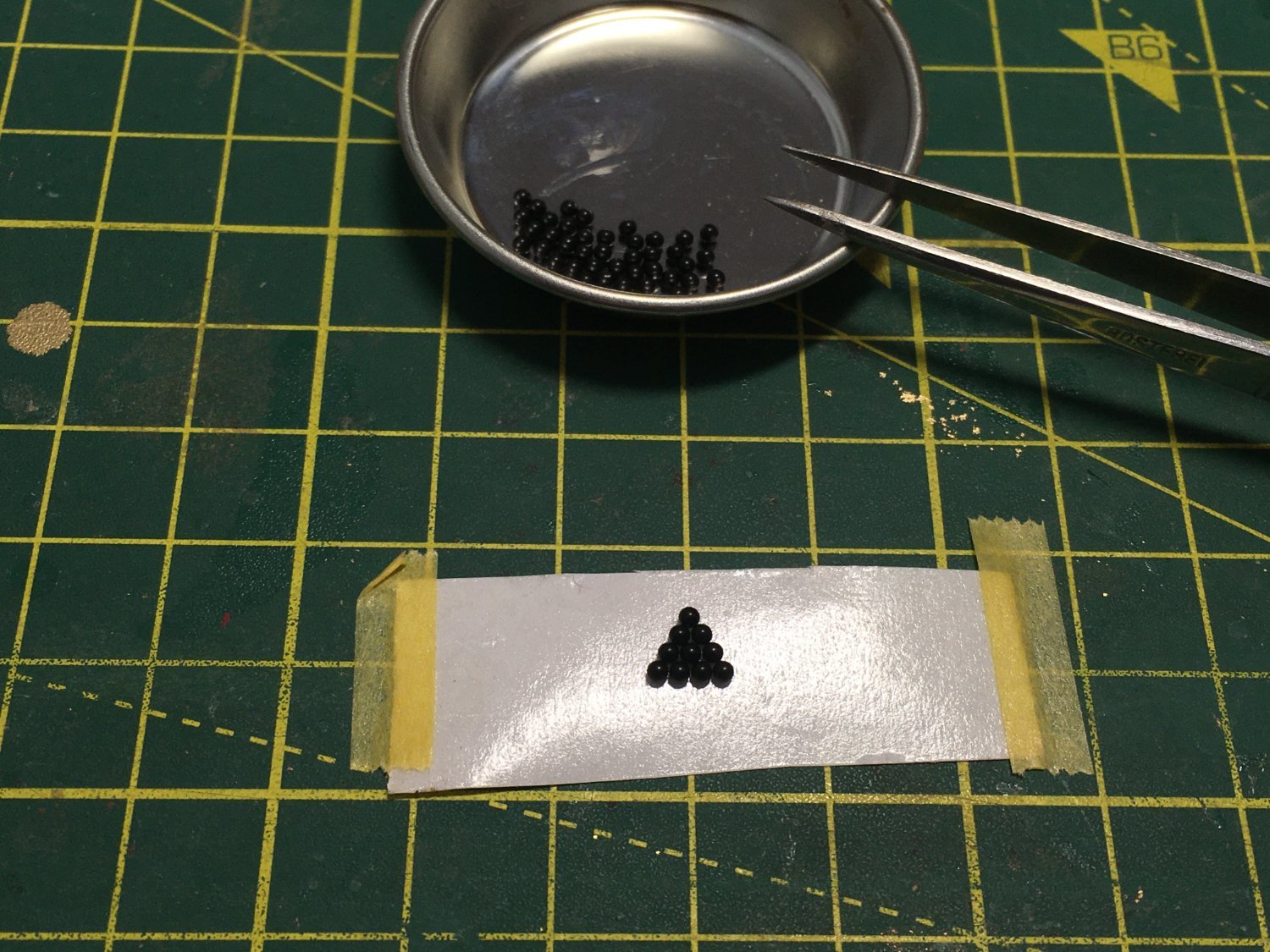
Lastly I thought I'd have a go at making up the shot garlands. Rather than building these on a piece of clear film as suggested in the manual I used double-sided sticky tape. Starting with one sticky side facing up and the backing paper still on the bottom face, it was easy to arrange the balls without them rolling around:

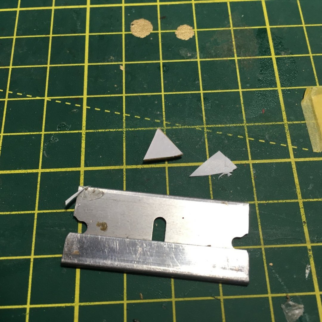
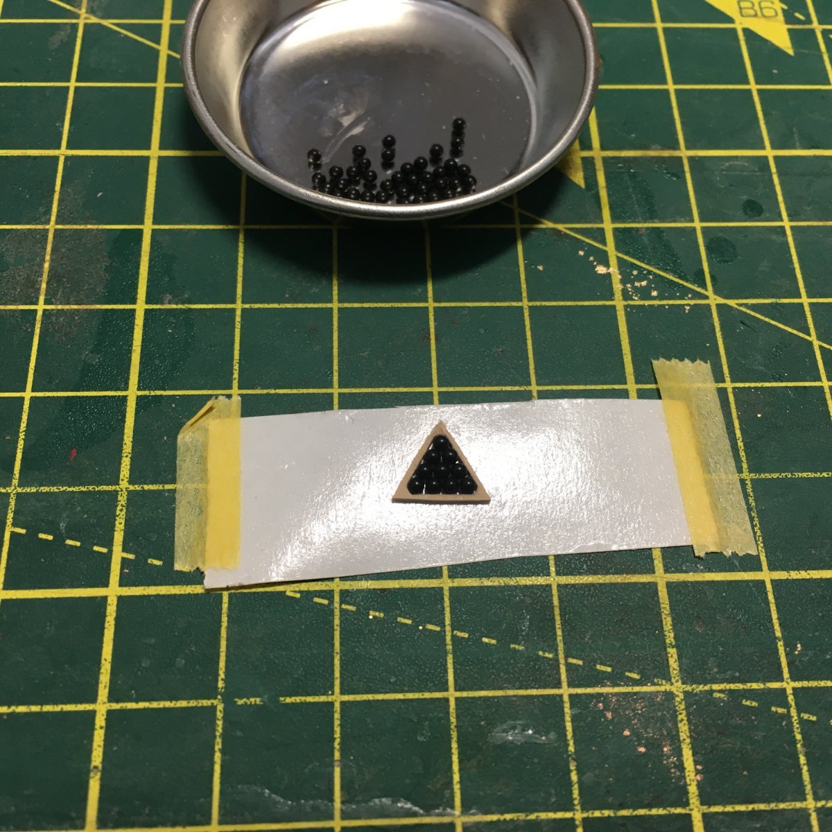
I had intended to build my own frame around the resulting triangle as I felt the kit garland was a little chunky. I'd done this for Royal Caroline and it worked well. However before committing to that I thought I'd try thinning the laser-cut kit garland down a bit, holding it very carefully against my sander. The result looks quite decent so I might go for this method:
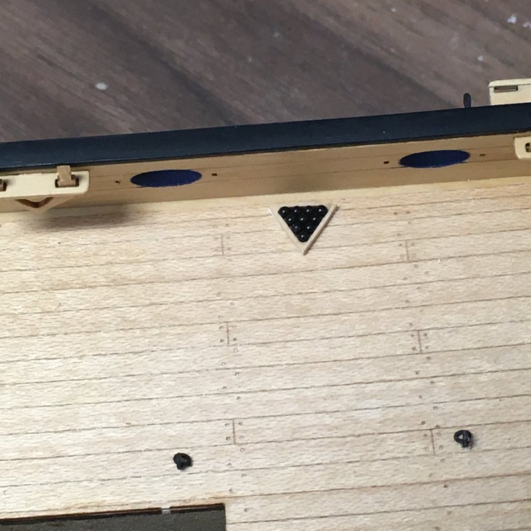
The next steps are to cut the triangle off the sticky tape, remove the backing paper then stick straight onto the deck:
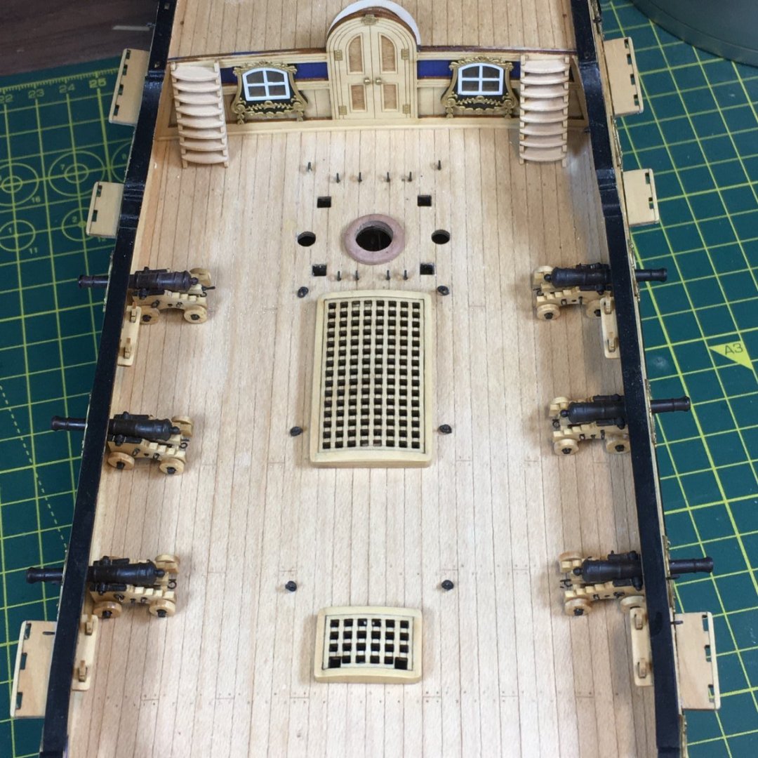
Looks like someone's about to start a game of snooker or pool!
Derek
-
-
Coming along fine. That main hatch definitely looks better for the slight curve. I think I might have done mine too much - your's looks just right. I'm leaving off fitting my winch and belfry and the rest of the deck furniture until I'm confident I've finished all the major structural stuff, otherwise it just gets in the way.
Derek
-
7 hours ago, rudybob said:
Thanks for the in situ heat and water tip
No problem. Most wood bending includes heat and/or water - if you've not seen them I'd recommend Chuck Passaro's videos which you'll find under Planking Techniques in the Modelling Techniques section at the top of the forum home page. Personally I try to use heat on its own where I can as water can cause unwanted expansion. See this link to my latest build where I describe ruining a major component by soaking it too long.
Derek
- Ryland Craze and bruce d
-
 2
2
-
53 minutes ago, The Gimps Chimp said:
Getting hold of the Gutterman mara thread is proving difficult here in the UK
I get mine here: https://www.williamgee.co.uk/shop/gutermann-threads-mara-100-5000m-cone/
They have plenty of #696 (for running rigging) and #854 (standing) in all different thicknesses.
- DaveBaxt, The Gimps Chimp and mtaylor
-
3
-
1 hour ago, glbarlow said:
I’m sure you plan to fully rig each one right
🤣😂🤣😂🤣😂🤣
-
Cannon
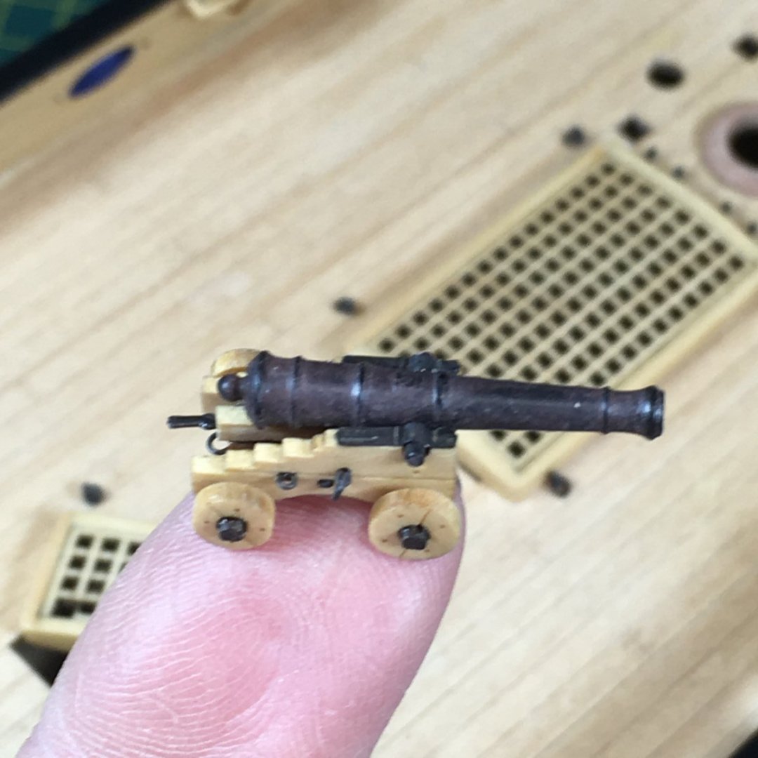
I haven't been able to spend much time in the workshop for the last week or so, just enough to potter around on a couple of odd jobs including making up one of the cannon:
Looking at the close-up the handle I've fitted in the quoin looks over-scale and I'll replace it with a smaller piece of wire. That apart, I'm reasonably happy with the result and will follow the same process with the remaining five guns. I'll just mention the main points of interest.
First, the char cleaned off well, the only tricky part being the wheel rims which I tackled by jamming them on a cocktail stick held in the lath:

I sanded the axles by hand to round them off then painted them black.
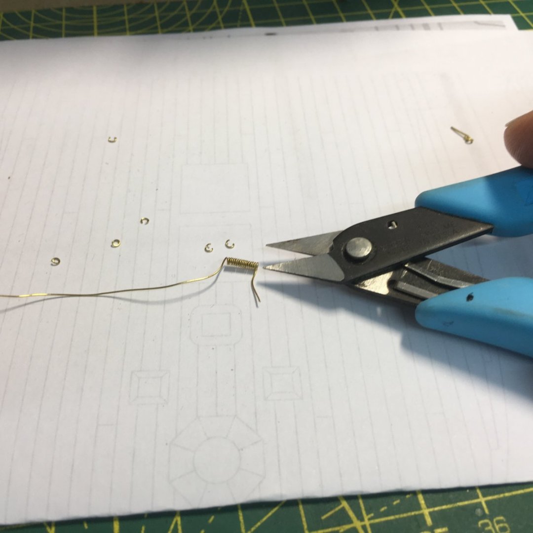
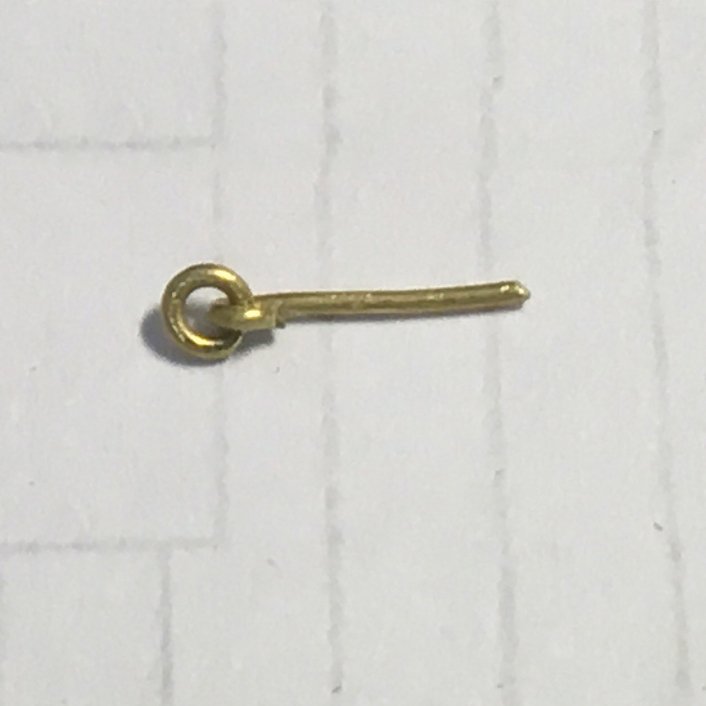
I felt the kit ringbolts were too big so I made my own with 0.3mm brass wire bent round a 0.5mm drill bit:

I used a slightly different technique for the breech rings. I described this in detail in my Speedy log, from which I've copied these photos which hopefully explain the technique:

I drilled 0.4 mm holes in the carriage as there was no provision for breech rings in the kit.
The barrel was painted with Admiralty Ironwork Black then lightly treated with rust coloured weathering powder.
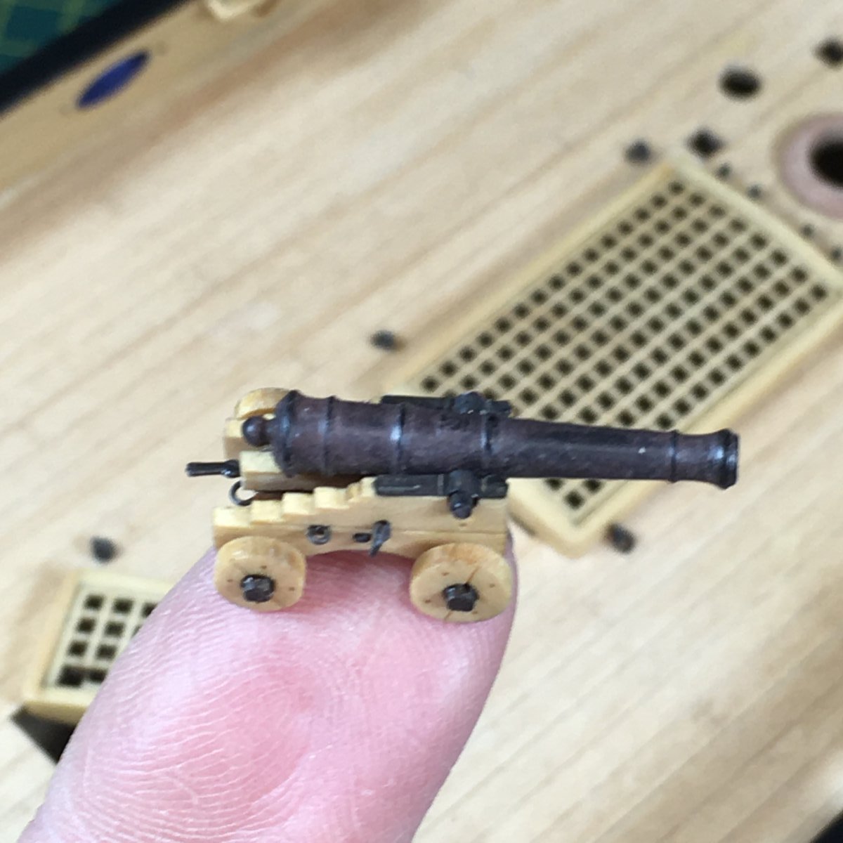
Here's the obligatory finger shot to show how small these little blighters really are:
Derek
- VTHokiEE, Rustyj, Blue Ensign and 14 others
-
17
-
Good job on the gunport patterns Bob. Even the best kits aren't intended to snap together like Lego bricks (they'd be boring if they did!) - you've shown that they need a degree of skill and perseverance to get good results. Well done!
Derek
- hollowneck, bruce d and BobG
-
2
-
 1
1
-
Excellent work as always B.E. - I found myself holding my breath when you described cleaning those fragile rails and volutes!
On 2/10/2022 at 9:41 AM, Blue Ensign said:One would imagine that a Captain would know how to spell his own ships name
Despite Dr Johnson's efforts I suspect spelling in the Georgian era was less standardised than he would have liked, and Captain Kendall probably just used the version he preferred.
Derek
- BobG, hollowneck, Blue Ensign and 1 other
-
4
-
Just catching up with your log Bob. Looks like you're off to a good start, and well done for recording the full journey. I get a tad suspicious when I read a log where the builder sails serenely from a pile of wood to a superb model without a single hitch on the way. For me overcoming problems and rectifying mistakes is part of the fun of our hobby, and recording them in a log not only helps others but reduces the chance you'll suffer the same problems on future models. I'll enjoy following along.
Derek
- Theodosius, glbarlow, BobG and 2 others
-
5
-
-
-
Good work on the cannon David. A couple of points:
5 hours ago, desalgu said:I was doing very tiny parts, and I believe I didn't keep them separated by stirring enough while blackening. Some blackened fine and others not so good.
I found the same problem. For me, the answer was to put the parts in a small leakproof container with the blackening solution and shake them for a minute. That way I was able to treat 100+ components in a single batch.
4 hours ago, desalgu said:I really only used this to get a length for the breech rope, and it was still a bit of a guess.
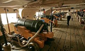
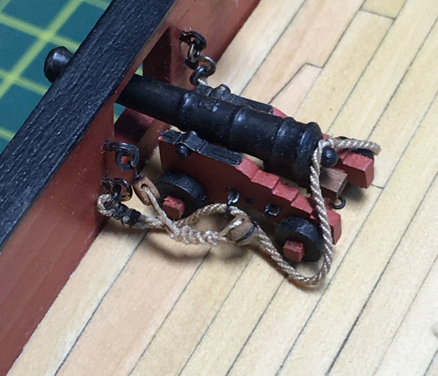
Breech ropes were generally 3X the length of the barrel (Lavery; The Arming and Fitting of English Ships of War, 1600-1815) to allow sufficient slack for just the right amount of recoil. I take that not to include the seizings, so for example with a 30mm barrel I would allow about 96mm to include short seizings at either end. If you make the rope too short it won't look right on the model - you should aim for it to drape down on the deck when the gun is run out, like this on the real Victory and my Speedy:

Sometimes breech ropes were frapped up out of the way, but they still had to have the same amount of slack.
You're getting well ahead of me! I've been spending time on one of my other hobbies, astronomy, so I'll need to get back to the workshop to catch up😁
Derek
-
-
-
-
Thanks guys, much appreciated.
On 1/26/2022 at 4:09 PM, Rustyj said:I don't have good luck blackening so I appreciate your advice and will give it a go
13 hours ago, desalgu said:After seeing what you do, I'll have to try blackening again sometime
I've found that blackening is like silver soldering - preparation is everything. Skimping on any part of the process will spoil the result. For me the game changer was the pickling bath that I read about in the forum post I referenced earlier. I couldn't find the Sparex brand in the UK but the jewellers' pickling solution I buy works fine. Apparently the "PH minus" products people use in spas and hot tubs also works. I can't vouch for that as my wife treats our spa as her personal domain and I'm not allowed near the chemicals. The second game changer was using the leakproof bottle to shake the components, enabling me to deal with large batches. The process may seem time consuming but once you develop a routine it's pretty straightforward and well worth the effort. Certainly a lot easier and more effective than painting!
One final point. If you lightly buff blackened components with a soft cloth or Q-tip they will look even more like iron - look at the cannon barrels in the earlier link.
-
I would also suggest you look at Vanguard Models, one of the forum sponsors. As well as top of the range warships, the designer Chris Watton has also produced a range of fishing vessels that provide a good introduction to planking. Manuals for all the Vanguard range are viewable and downloadable on the website, and there are many build logs on the forum. Here's a good example. I should add that Vanguard ship worldwide.
- Ryland Craze and BenD
-
2
-
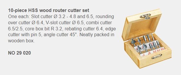
Belfry - an exercise in char removal!
I spent an inordinate amount of time on this task, mostly dealing with char removal and related issues. Don't get me wrong, I love the quality of the laser cut parts and for me they add greatly to the model, but they bring their own challenges. I have also noticed a difference in the quality since Chris got his own laser cutting machine, For example, on Speedy some of the tiny parts such as cleats tended to crumble - they were so small they were as much char as wood - whereas on the Duchess the laser seems to have achieved very fine tolerances with no bad effects. This allows great detail in the laser cut parts; the downside is that the more intricate parts are more challenging to de-char. This is particularly true of the end grain where the char seems to be particularly stubborn, and of course the end grain on components cut from flat sheets can appear in a variety of places. Also, I'm working in boxwood which tends to show the char more than pear.
I use a combination of scraping, filing and sanding to remove char. I've even resorted to taking off fine slices on the table saw and mill. Sometimes however even that isn't enough, as evidenced by the belfry where I just couldn't get rid of the striped effect created by the end grain of the main upright sandwiched between two veneers:
I considered several options including painting the belfry and fitting a copper roof. I decided to maintain as much of the bare wood look I've gone for with this model. The solution was a spare piece of boxwood cut to 0.4 mm on the Byrnes saw. I soaked it in boiling water for five minutes before clamping it to the belfry and leaving it to dry. I reverted to wet bending as I didn't think dry heat would work on such a short length with two fairly tight changes of direction. Anyway it worked. Once dry I clamped it again, this time with PVA:
Here it is after a light sanding:

Incidentally I've fitted the metal handle for the bell. This isn't described in the manual but is listed in the parts and shown on the plans. From a practical perspective it saves crew having to climb on the winch to ring the bell! The slightly tricky bit is ensuring the pin holding the bell is very short, otherwise it'll foul the hole required by the handle.
The next job will be preparing the winch that sits just aft of the belfry.
Derek
-
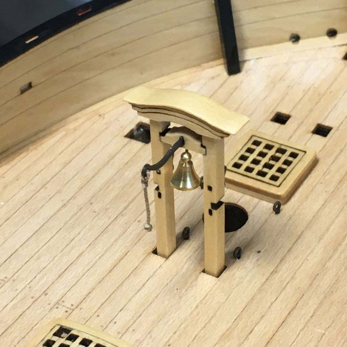
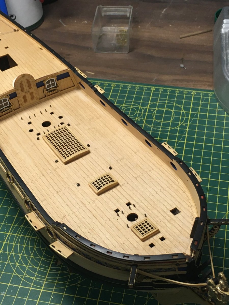
Gratings & Blackening Revisited
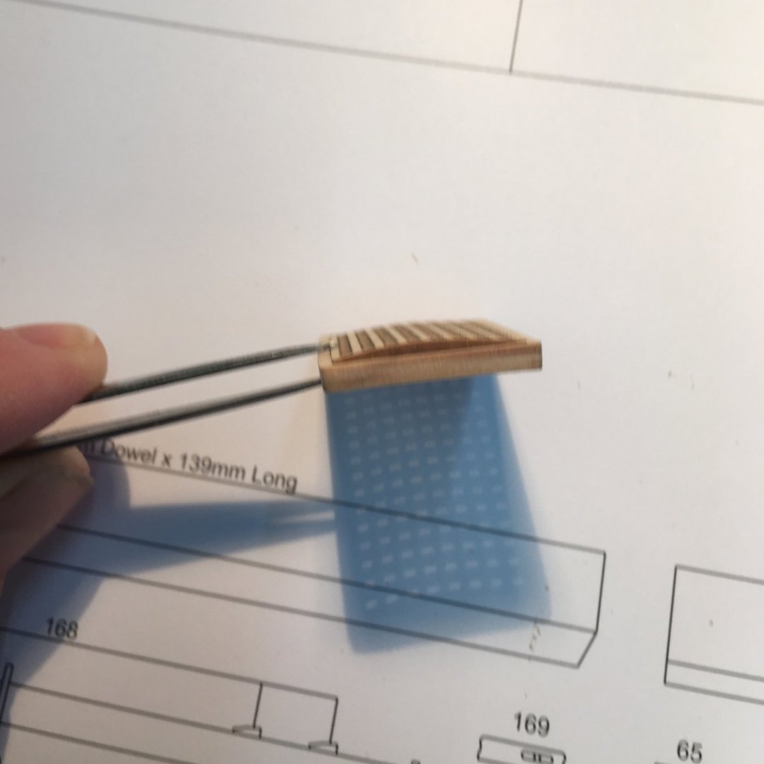
The bending method I tried out on the main hatch worked equally well on the hawse hatch:

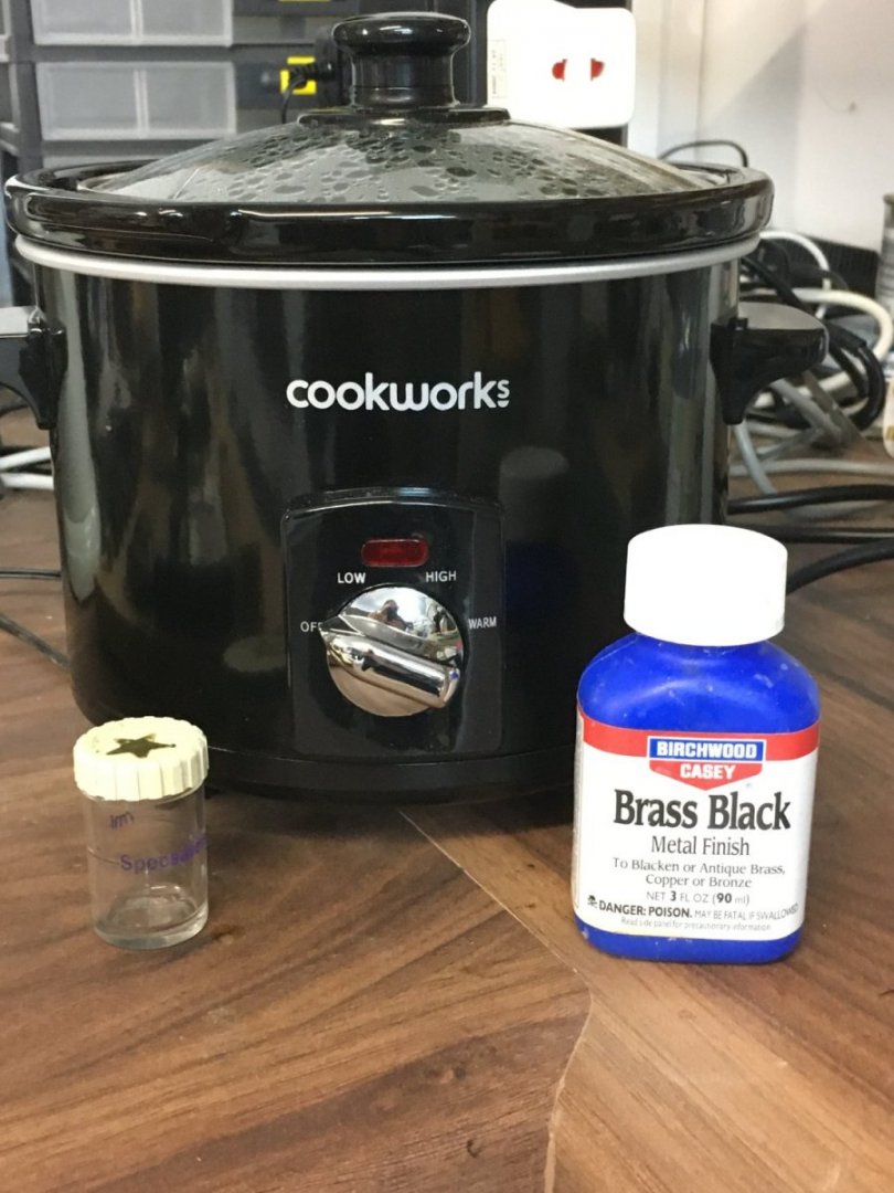
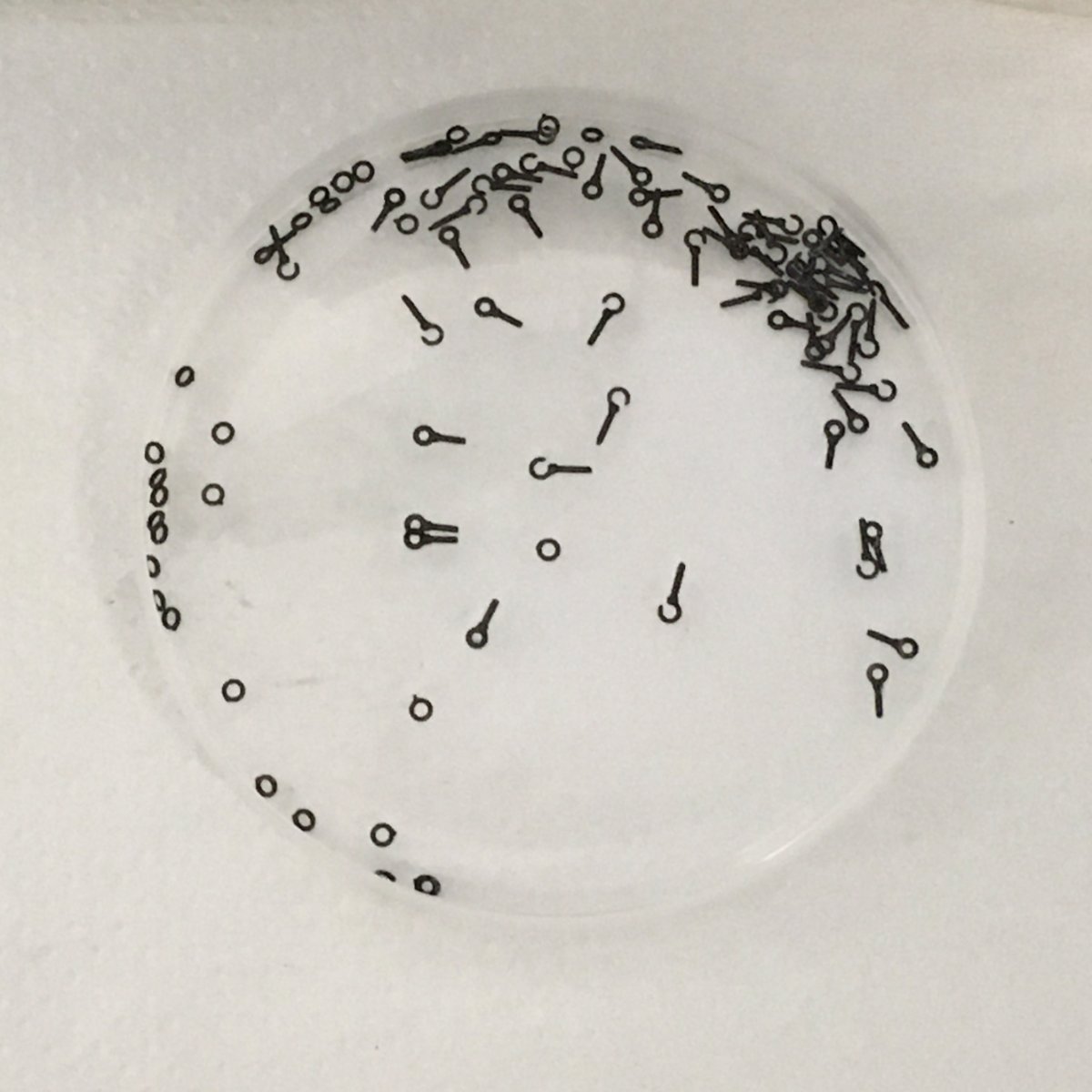
With lots of hooks and ringbolts to blacken I decided to revisit the process I use. For some time now I've used Birchwood Casey Brass Black in conjunction with the preparation method I found here on the forum. In brief, I put the pieces to be blackened in jewelers' pickling solution heated in a slow cooker for 10 minutes (holding small components in a plastic tea strainer for ease of handling), then into a baking soda solution to neutralise the acid, then isopropyl alcohol for final degreasing (others use acetone but I prefer IPA) and finally a minute in Brass Black before rinsing in water. Generally this works well, the only problem arising when I have to blacken large numbers of small components and I find it difficult to ensure all surfaces get properly treated. Consequently I would find myself doing lots of small blackening runs. The solution when I thought of it was so obvious I was annoyed with myself for not thinking of it sooner. I found a small plastic container that my wife had years ago for cleaning contact lenses and was therefore leak-proof. Here it is alongside the slow cooker (£cheap from Argos):
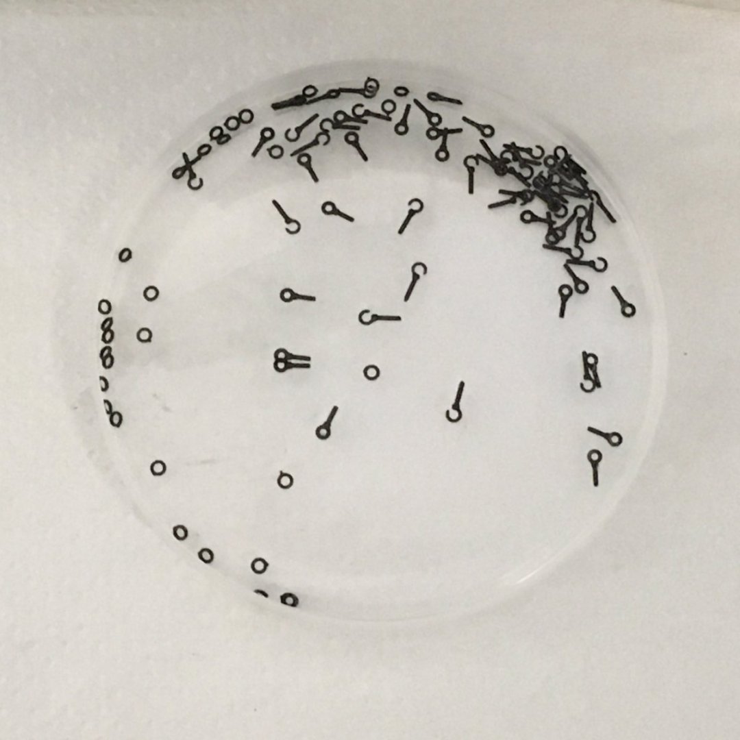
Once out of the baking soda, put the components in the container with a few drops of IPA, shake vigorously, rinse and replace with Brass Black, shake again and rinse. Result - I was able to treat over 100 items in one go, all well and evenly blackened:
It's not easy to see on this photo, but the pumps didn't blacken quite so well. However I think that was because I'd glued the components together before blackening them and some of the CA had leaked where it oughtn't. Not a problem that some minor touching up won't solve.
More deck furniture next.
Derek
-
Gratings
The kit supplies nicely made wooden gratings and coamings for the fore, main and hawse hatches. The gratings on Speedy were photoetch which, although well made, didn't allow me to camber them. On previous build I had cambered gratings by rubbing them against sandpaper stuck to a board with a gentle concave curve. However the Duchess's gratings come with very finely etched lines to represent the battens and ledges and I didn't want to lose them, deciding instead to use heat bending.
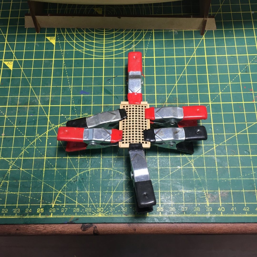
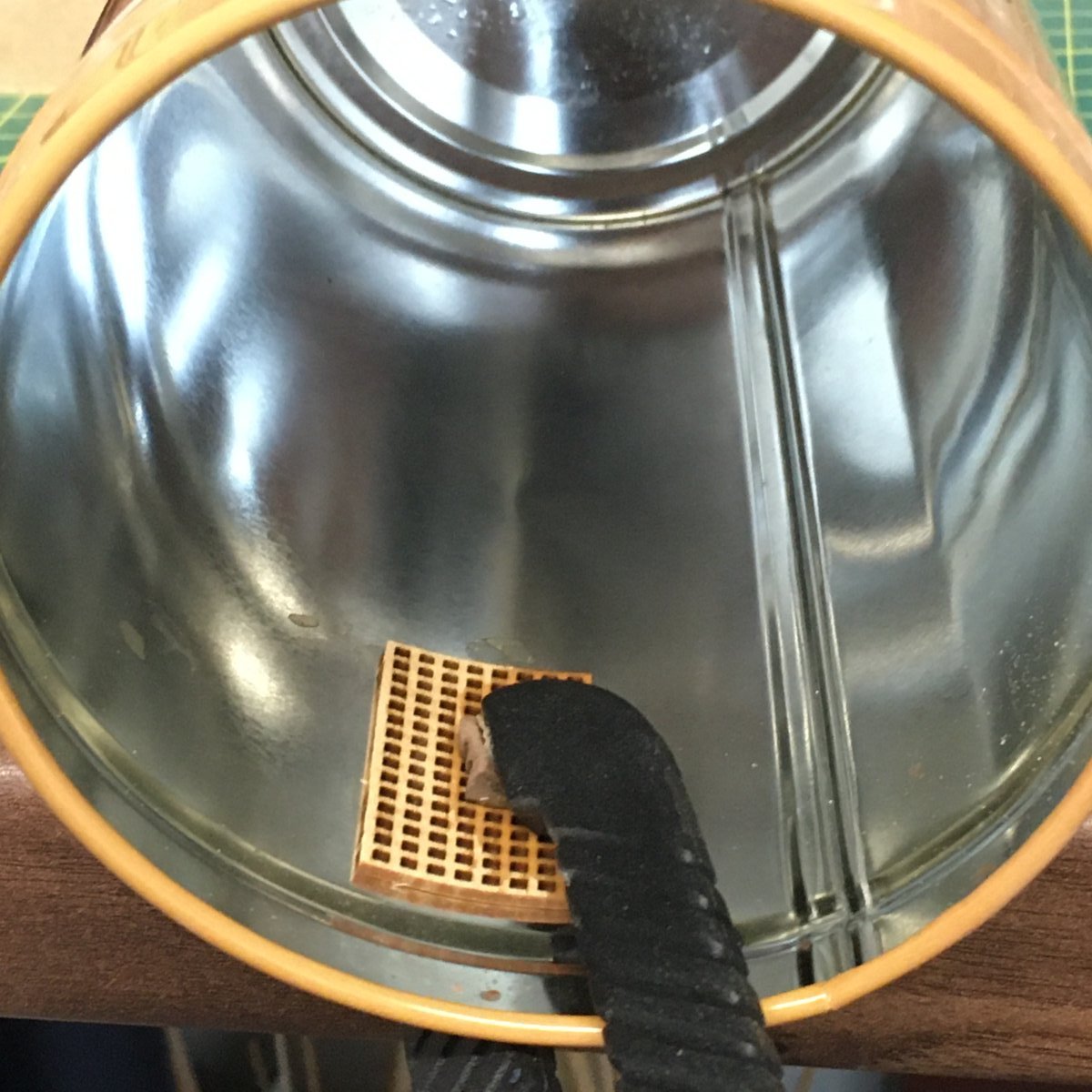
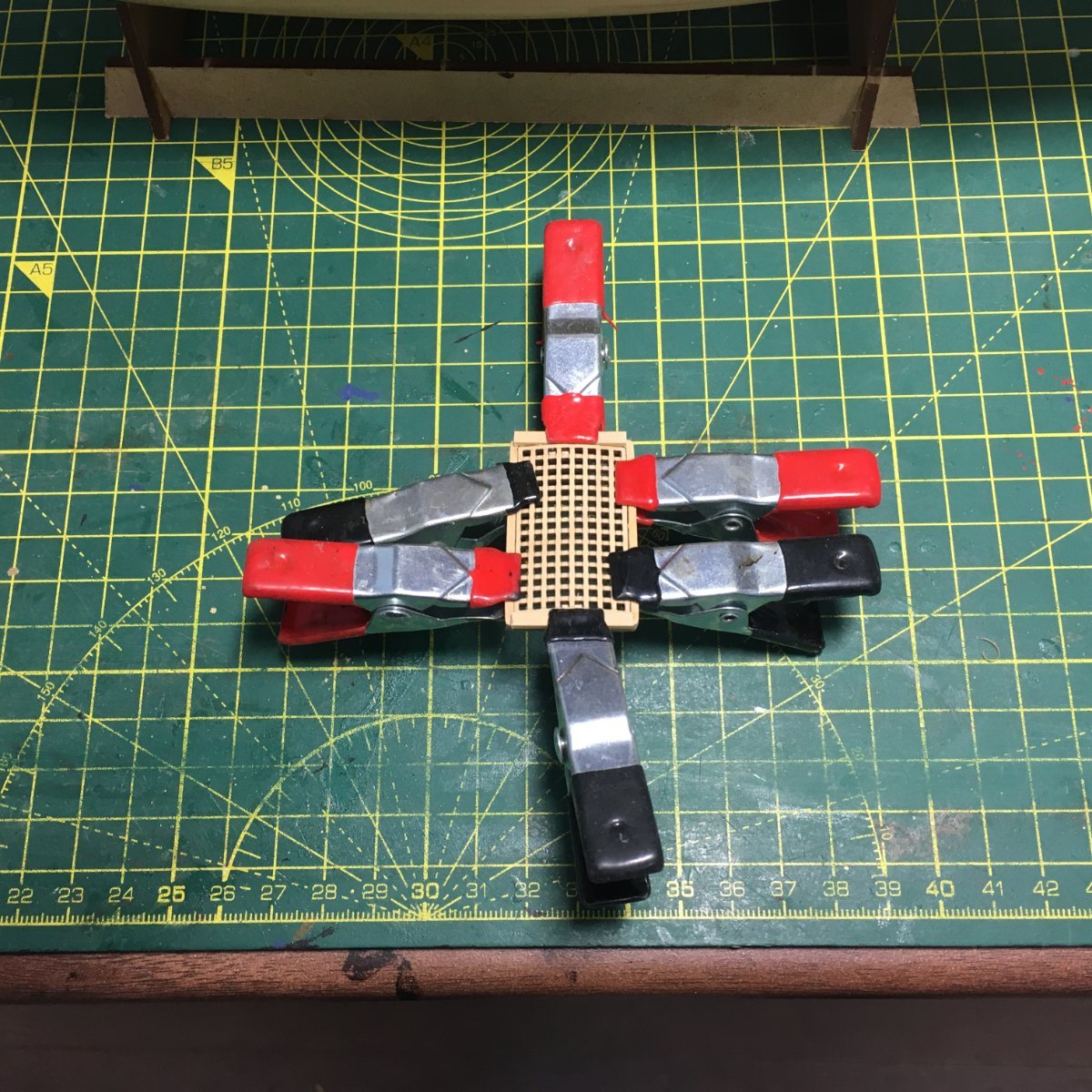
Starting with the main hatch as a test piece, and with a fair degree of trepidation, I put it in freshly boiled water for a few minutes before clamping it face down inside a tin of the right diameter. I tried using the outside but found it was too tricky trying to get two clamps on such a small component. One clamp in the middle on the inside did the job:

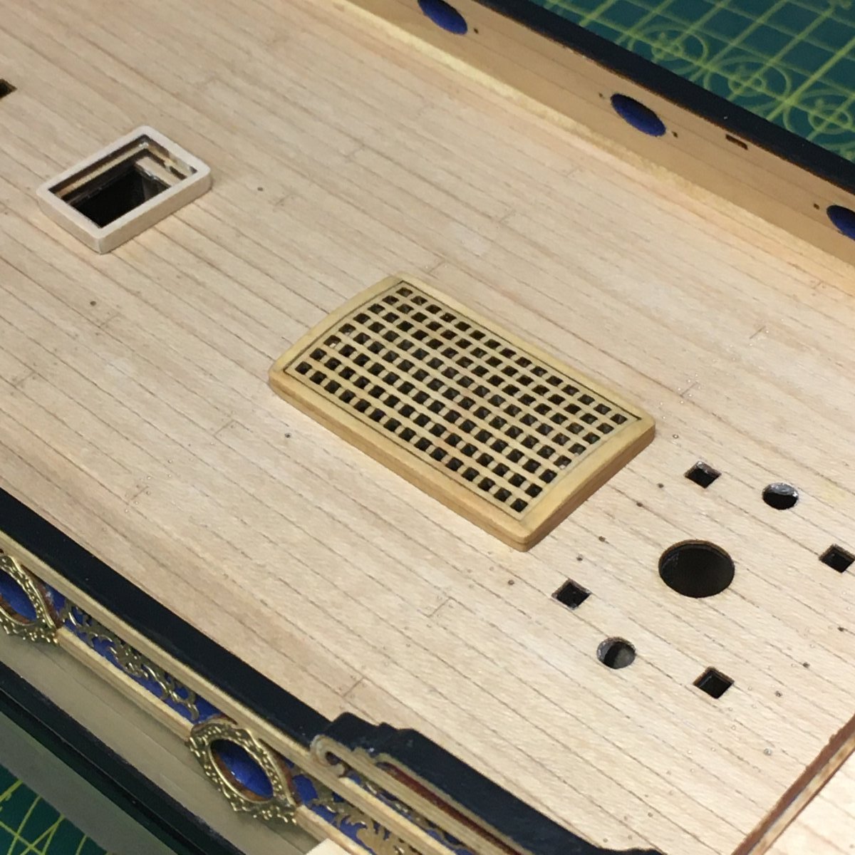
Once dried the grating fitted neatly in the coaming with a pleasing camber - apologies for the poor focus but I was holding my phone one-handed:
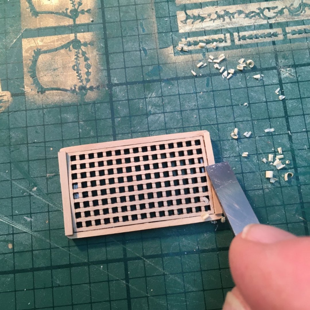
The next job was to add a curved section to each end of the coaming to match the grating. I started by gluing two small pieces of scrap boxwood to the coaming. Once dried, I pared down the excess with a mini chisel and finished with sandpaper:
Here's the final result:

Worth the bit of extra effort, I think. I'm pleased that it's still possible to see the battens running fore and aft, as they should. Now I know the method works I'll try it on the hawse hatch. Although it's a lot smaller I should be able to impart a slight camber if I'm careful. However the fore hatch is a lot smaller still - the grating's only about 10mm square - so I'd be on a hiding to nothing if I tried to bend it. Besides, it's so small I suspect any camber would be almost imperceptible.
In between finishing hatches I'm planning to start blackening batches of ringbolts which need to be in place before I fit the deck furniture.
Thanks as always for the likes and supportive comments.
Derek
-
More great work, some of which I'll shamelessly copy. I'll try that wood dye as an alternative to spraying, which I find a pain - especially the cleaning up. I'm also seriously tempted to get one or two of Chris's new boats.
Derek
- mtaylor and hollowneck
-
2
-
Completely agree about the PE parts, especially the belaying pins which are far better than the out-of-scale Christmas tree bulbs that masquerade as pins in most kits. None of the hooks and eyebolts look flat when viewed normally on the model. The only ones I changed on Speedy were the ringbolts on the gun carriages - not because they looked flat but just because they looked a little large to my eye. They were easy to replace with home made versions.
-


Duchess of Kingston 1778 by desalgu - Vanguard Models - 1:64 - Royal Yacht
in - Kit build logs for subjects built from 1751 - 1800
Posted
I've used the same method I tried on Royal Caroline. I don't know if it's clever but it's simple enough for me. Here's the link to my log.
Derek