druxey
-
Posts
13,405 -
Joined
-
Last visited
Content Type
Profiles
Forums
Gallery
Events
Everything posted by druxey
-
 Just pulling up a seat for this one. Looking good!
 -
L'Amarante by marsalv - 1:36 - POF
druxey replied to marsalv's topic in - Build logs for subjects built 1501 - 1750
Sweet! -
Great going - especially the 'fiddly bits'!
-
Lovely work as usual. However, I am curious; Why do you not use a drawplate and split bamboo to make your treenails? It's much more time and labor effective.
-
Good questions. I think you need to do your own research. Look online in the RMG site. Check not only the plans, but contemporary model photos as well. An example: https://www.rmg.co.uk/collections/objects/rmgc-object-66464 Blow up this image. Although lo-res, you can see that the fore face of the bollard timber projects forward of the hawse timbers, above the line of planking - in this case.
-
Freehand drilling? I usually drill an undersized hole, then open it out making any correction.
-
Yes, reaching around is usually fatal! If you can rig a lazy susan to revolve the model instead may help stop that evil habit!
-
My method is to use a long length of wire, and bend one end into a short 'V'. Then thread on the ring. The next step involves holding the two end of the V (inverted so gravity moves the ring out of the way) )in a parallel plier and squeezing the V together using a needle-nose pliers. I then release the ringbolt and, with fine wire cutters, cut the short end at an angle and then the longer end to make a stem. As observed by Gregory, the bolt is partially sunk into the wood. After drilling a suitable hole, I open it up using a miniature jewelers' screwdriver tip held at about a 35 degree angle. This forms a sort of countersink for the ringbolt.
-
Yes, Caruana was a principal source.
-
It looks like you have found your medium, Aleksandr!
-
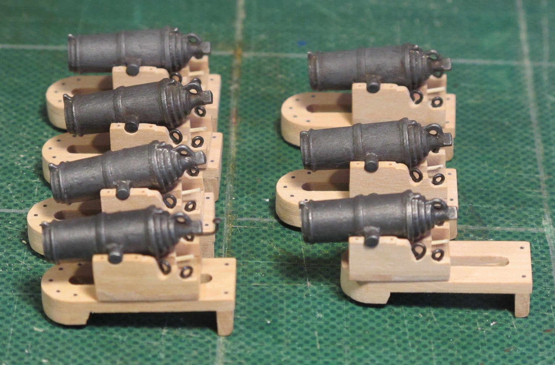
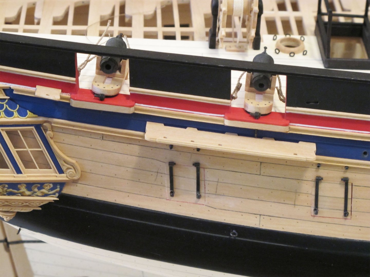
Early carronade mounts are a subject in themselves. This was something I delved into some years ago for a 1782 fireship. From the evidence I could uncover in Caruana and elsewhere, the early carronades were mounted on the 'outside principle' and had no muzzle extension to limit blast spread. Also, there were no wheeled trucks on the inboard end of the slide. I'm about to read your pdf and may have some additional comments later.

-
It's clear that you are having too much fun fitting out the accommodation. Well done!
-
Well done, Mark.
-
While the use of wax or modeling clay (Plasticene) is very helpful to work out the problems of a carving in 3D, the process is quite different. In the case of carving, the process is subtractive, while modeling using a plastic material is additive. Sure, one can carve wax and clay, but if a mistake is made , one simply adds more material. Try to do that with stone or wood!
-
Welcome here ! Nice job on the pram. The puzzle under it looks challenging as well!
-
Well done, DocTom. The lessons learned that you stated are both important to becoming a first rate model maker.
-
Great result, but very labor intensive!
-
Lovely work, as usual. Best wishes for a far better New Year.
-
Fascinating. The 17th century English fashion paice was set is a similar way and, by the end of the 1600's, the two radius stem was also used, although sometimes in a slightly different way. Usually the lower radius ran smoothly to the keel. In other examples there was an angle at the forefoot as your example.
- 49 replies
-
- 1
-

-
- Wildmanden
- Turesen
- (and 1 more)
-
Must have been a challenge to bevel plywood! Result look s very good.
-
Sail feedback request, Mondfeld method
druxey replied to travis's topic in Masting, rigging and sails
Curious. I've never known real Silkspan to tear like that. It is, in fact, very strong. Are you sure that this was, in fact, SilkSpan? -
Ah; chip happens!
-
Make sure the blades are sharp enough and take very light cuts to prevent thin bits splitting off. Of course, if there is a flaw in the wood itself.... Linden is lime wood, not boxwood, by the way.
-
Sail feedback request, Mondfeld method
druxey replied to travis's topic in Masting, rigging and sails
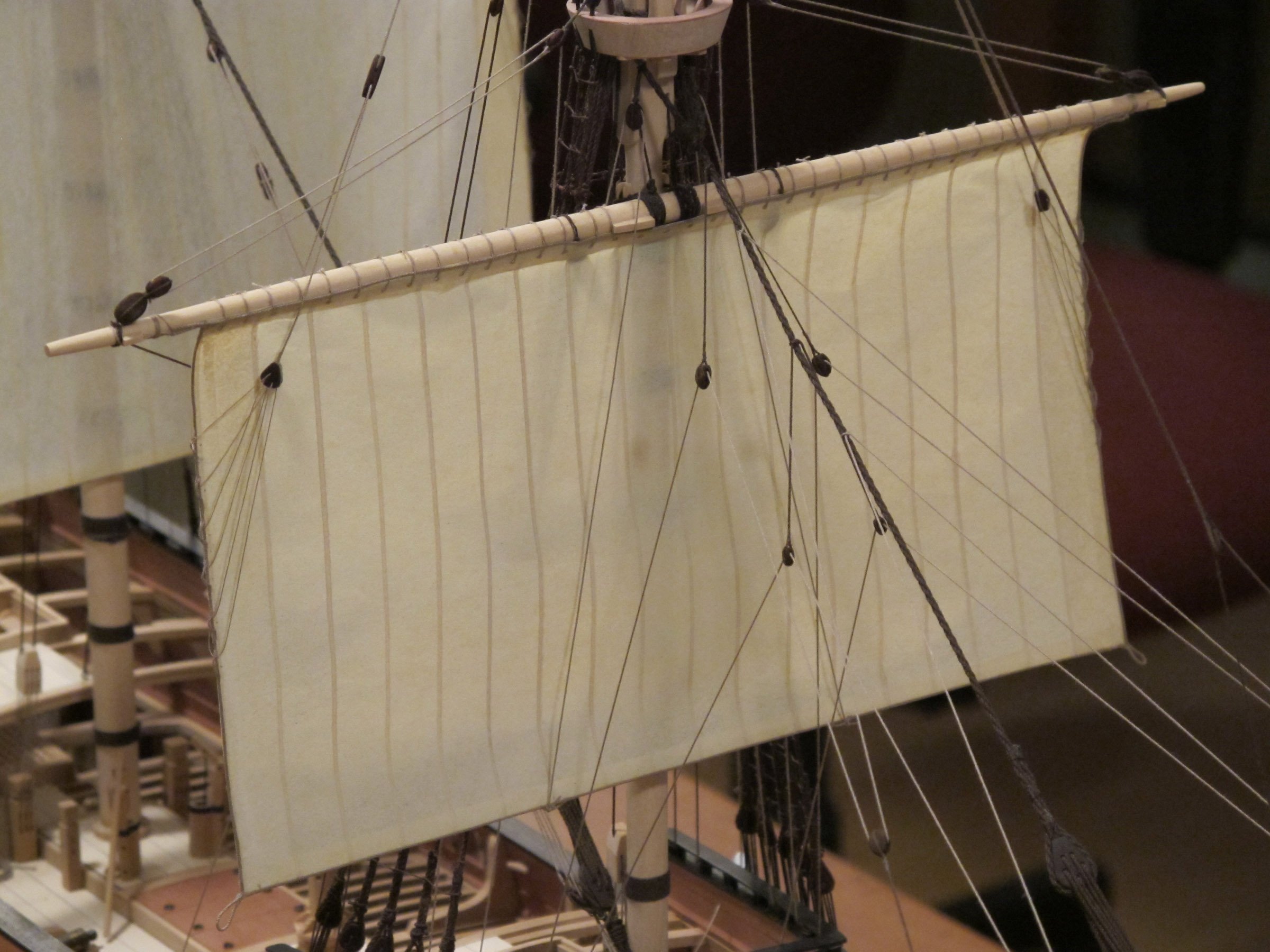
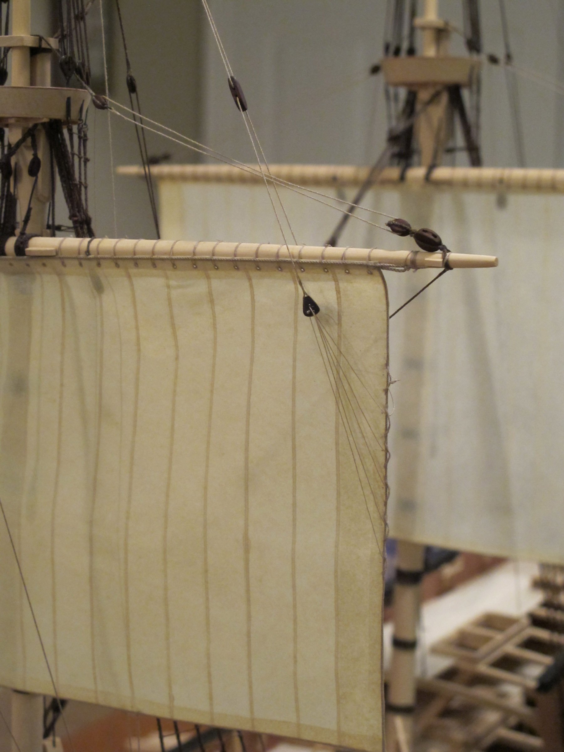
You've done a very neat job, but there is basic problem of scale. You mention 1:60, and one can never stitch that finely to be even close to scale, as well as the material is over scale thickness. What youa re doing is also very labor-intensive. Now, if that's the way you want to do it, read no further! A better way, IMHO, is to uses the material called SilkSpan. It is essentially a thin but strong paper product. The overlaps can be easily simulated with acrylic paint applied using a bow pen. The reinforcing edges are glued and rope also applied using white glue or matte acrylic varnish. An example is pictured below at 1:48 scale. Instructions of how to make sails using this technique are available through SeaWatchBooks: https://seawatchbooks.com/products/swan-iv-sail-making-supplement-from-the-revised-and-expanded-edition-by-david-antscherl

-
Sorry, but Miller in his day had a different meaning in his title 'model' - it could mean 'ideal' here or plan, as well as, less usually then, a model as we understand it now. (A 'platt' was also a plan.)