druxey
-
Posts
13,374 -
Joined
-
Last visited
Content Type
Profiles
Forums
Gallery
Events
Everything posted by druxey
-
 This gets more interesting! Thanks for the replies on the fore ports.
- 1,051 replies
-
- 2
-

-
- cheerful
- Syren Ship Model Company
- (and 1 more)
-
I'd say your right leg would be a good source, Pompey, if you are desperate!
-
Not an entirely satisfying answer, Chuck, but thanks for trying! If the windlass and bitts were moved 2' 0" aft, I could see that it might just be possible on the starboard side. The bowsprit would still intrude on the port side, though....
- 1,051 replies
-
- 2
-
-
- cheerful
- Syren Ship Model Company
- (and 1 more)
-
Often 're-makes' give fewer headaches down the road than 'fix-ups'. Those station lines are good reference points for other structures, but if you shift some of the frames and not others, you'll end up confusing yourself. If I may advise, the re-make route is the better one.
- 525 replies
-
- 3
-
-
- anchor hoy
- hoy
- (and 1 more)
-
Looking great, Chuck. One thing that's puzzled me for years is why there were large ports placed right up in the bows. There's no space to move, much less work, a cannon or carronade of any sort. Do you have any idea of the purpose of those ports?
- 1,051 replies
-
- 5
-
-
- cheerful
- Syren Ship Model Company
- (and 1 more)
-
Real progress visually now, Frank. That is looking great!
- 649 replies
-
- 6
-
-
- dunbrody
- famine ship
- (and 2 more)
-
Try seeing how 6' 0" above deck looks for a starting point.
- 649 replies
-
- 3
-
-
- dunbrody
- famine ship
- (and 2 more)
-
Nice simple method for ensuring the partners are on the centreline, Frank.
- 649 replies
-
- 7
-
-
- dunbrody
- famine ship
- (and 2 more)
-
One can never have too much line! I think you will be happy with Syren's cordage.
- 24 replies
-
- 1
-
-
- three sisters
- schooner
- (and 1 more)
-
Your choice, of course; but in the lower picture the boat hull looks a bit naked without its garboard strake!
- 269 replies
-
- 4
-
-
- Queen Anne Barge
- Syren Ship Model Company
- (and 1 more)
-
If you are working with rigging thread, you might wish to consider the line that the Syren Ship Model Company produces. (Scroll down and click the link on the right side of the cover page of this site for the Syren web site) It is produced in many diameters and is probably the best commercial line available. And you are right: patience is the word for any model work!
- 24 replies
-
- 1
-
-
- three sisters
- schooner
- (and 1 more)
-
Check the SeaWatchBooks site. I'm not sure of publication date, but it should be out sometime in the next three months, all other things being equal. Thanks for your interest!
- 641 replies
-
- 8
-
-
- greenwich hospital
- barge
- (and 1 more)
-
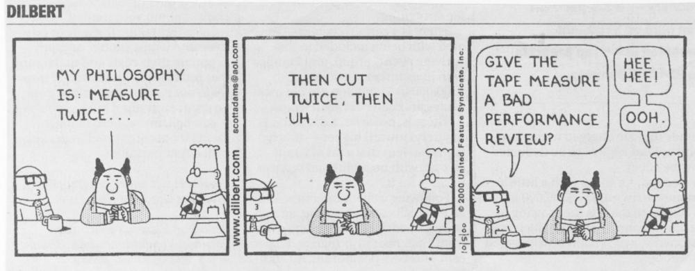
Two feet short? Reminds me of my favourite Dilbert cartoon (Hope I'm not infringing copyright by showing this, but it's too good not to share):
-
Steamboats and other rivercraft - general discussion
druxey replied to Cathead's topic in Nautical/Naval History
My mistake: I'm remembering this from nearly 40 years ago, Gerhard! Thanks for the correction. However, looking at the photos you've linked, this was a much older Edeltraud that I recall.- 281 replies
-
- 2
-
-
- Steamboats
- riverboats
- (and 3 more)
-
Yes, Landrotten, that's one of many techniques that will be included. Slainte!
- 641 replies
-
- 6
-
-
- greenwich hospital
- barge
- (and 1 more)
-
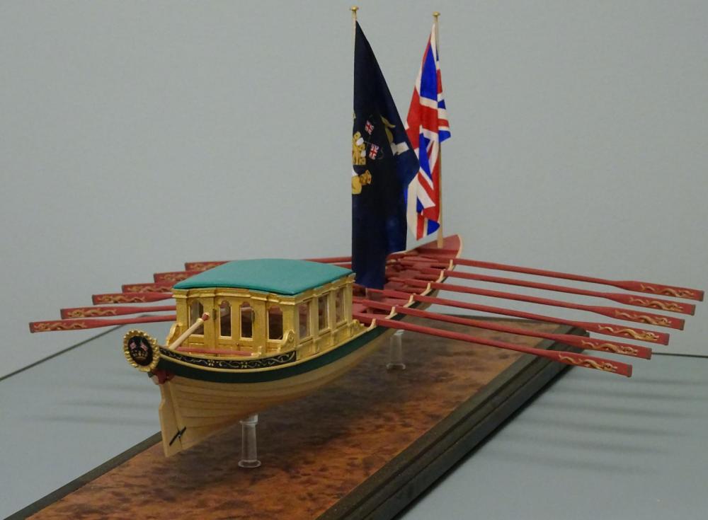
Postscript: Since the last posting there have been revisions! The sweeps were discovered to be sized for a single-banked boat not, as in this case, for a double-banked one. So, a new set of 12 sweeps have been made, 15' 0" as opposed to 19' 0". I also took this opportunity to paint the dolphins on one side the correct way up! Now, at the risk of incurring the wrath of the moderators, I'd like to mention that the full story, along with various techniques of making small open boats will appear in a full-color book shortly. Stay tuned! Again, my thanks to all who contributed to this log. You helped to make a better model.
- 641 replies
-
- 41
-
-
- greenwich hospital
- barge
- (and 1 more)
-
I'm amazed that, with children, you still have time and energy for a strenuous build! My model at that time was put away under plastic for ten years while my daughter was young. You have my respect, Gary.
-
Brilliant - as usual! Love the tooling as well as the final product.
- 281 replies
-
- 1
-
-
- falls of clyde
- tanker
- (and 2 more)
-
Oops. my apologies, Frank. (Excuse: I was always poor at remembering people's names!) I agree: wood.
- 649 replies
-
- 4
-
-
- dunbrody
- famine ship
- (and 2 more)
-
Coming along beautifully, Albert. The knees (standards, if they are that way up!) look right. I doubt if anything would be stowed along the midline anyway.
- 649 replies
-
- 4
-
-
- dunbrody
- famine ship
- (and 2 more)
-
See the pics I posted on your model log, MK.
-
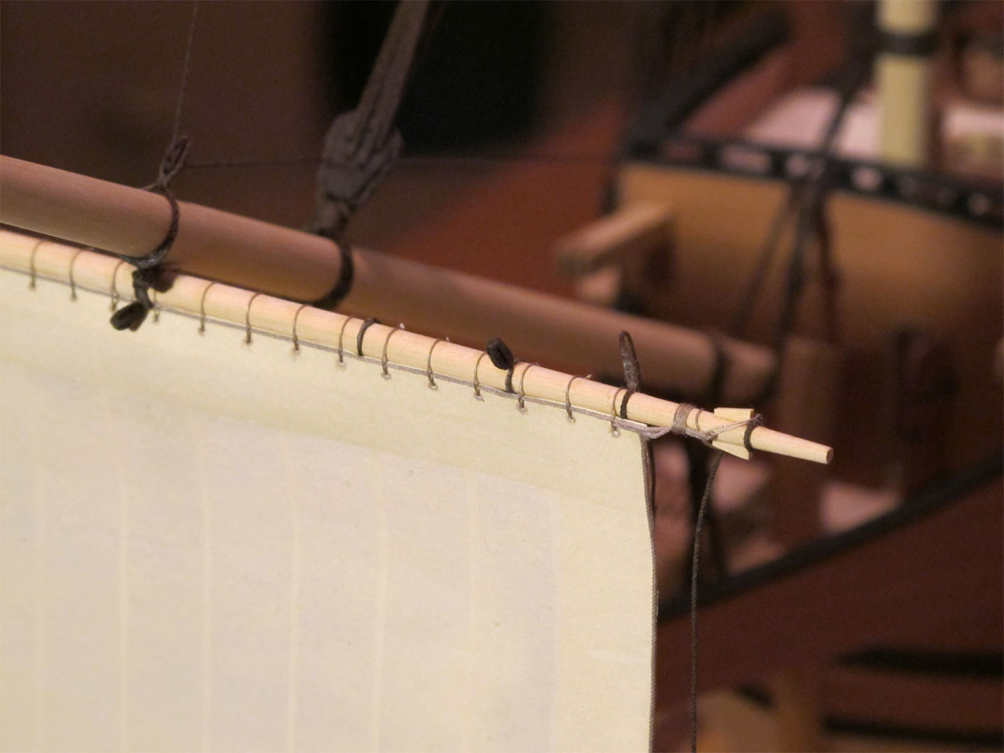
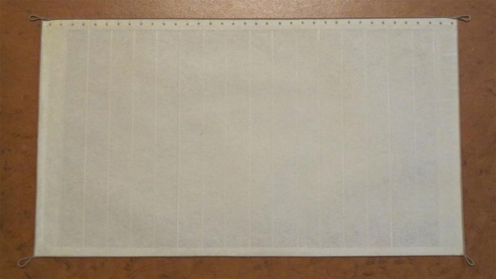
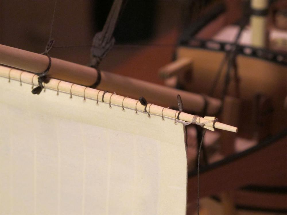
Don't try to sew at that small scale, MK. Take a look at paint on SilkSpan and glued bolt ropes, etc. in the photos and see what you think.
- 29 replies
-
- 2
-
-
- santa maria
- amati
- (and 1 more)