


druxey
-
Posts
13,368 -
Joined
-
Last visited
Content Type
Profiles
Forums
Gallery
Events
Everything posted by druxey
-

Mast Lengths and their above deck heights for HMB Endeavour
druxey replied to dashi's topic in Masting, rigging and sails
What does the mizen diameter at the partners measure on the draughts that you have, Dashicat?- 63 replies
-
- 2
-

-
- HMB Endeavour mast lengths
- above deck mast heights
- (and 3 more)
-
Nice to see you back at the workbench, Siggi! I'm looking forward to see this model progress.
- 58 replies
-
- 4
-
-
- barge
- ships boat
- (and 1 more)
-
Mast Lengths and their above deck heights for HMB Endeavour
druxey replied to dashi's topic in Masting, rigging and sails
One further thought: Measure the diameter of the mizen on the NMM (RMG) draughts. Extrapolating from that, what would be the mizen lower mast length? Perhaps that will settle the question for you.- 63 replies
-
- 3
-
-
- HMB Endeavour mast lengths
- above deck mast heights
- (and 3 more)
-
Mast Lengths and their above deck heights for HMB Endeavour
druxey replied to dashi's topic in Masting, rigging and sails
I'm sure that there were exceptions in 1768, Dashicat. However, if you look at contemporary plans, generally you will only see mizen steps on the lower deck from the mid-1780's onward. Check out ships' plans images on the Royal Museums Greenwich web site.- 63 replies
-
- 1
-
-
- HMB Endeavour mast lengths
- above deck mast heights
- (and 3 more)
-
Enjoy your holidays, Paul!
-
Mast Lengths and their above deck heights for HMB Endeavour
druxey replied to dashi's topic in Masting, rigging and sails
The mizen mast was stepped on the keelson until late in the 18th century. I suspect Endeavour was stepped in this earlier style. It is irritating that contemporary draughts all omit showing any mast steps!- 63 replies
-
- 2
-
-
- HMB Endeavour mast lengths
- above deck mast heights
- (and 3 more)
-
Nice result, Frank. You might wish to back up the clamp with a scrap of hardwood to prevent tear-out on the drill exiting.
- 649 replies
-
- 7
-
-
- dunbrody
- famine ship
- (and 2 more)
-
HMS Naiad 1797 by albert - FINISHED - 1/48
druxey replied to albert's topic in - Build logs for subjects built 1751 - 1800
Lovely looking and great progress, Albert. If you are planning on planking the lower counter, it's easier to do this before adding the wale planking. -
To stiffen SilkSpan, dilute acrylic paint or matt medium - no need for nasty organic volatiles!
-
Well, I hope that the charges are inert! Neat solution to the problem of unscrewing the fuses without damaging them. Well done.
-
I am reminded of an anecdote about Oscar Wilde. In company one evening, he made one of his witty remarks. Someone laughed and said "I wish I'd thought of that!" Oscar replied, "Oh, you will, you will!" I'll think of cutting bands to exact length that way soon, Ed.
- 3,618 replies
-
- 9
-
-
- young america
- clipper
- (and 1 more)
-
Cutting the bands to length using your method is a brilliant idea, Ed! Thank you.
- 3,618 replies
-
- 7
-
-
- young america
- clipper
- (and 1 more)
-
I've used SilkSpan for sails and flags. There is a booklet on this technique from SeaWatchBooks: Swan, Volume IV, Sailmaking Supplement that may help.
-
I think, while you are correct, Michael, in saying the damp towel will expand the wood; once the humidity level returns to ambient, the wood will shrink back again. This treatment is only a temporary fix, unfortunately.
-
Interesting conundrum, Bill. Two out of three sources don't show this port. The VdV and Boston images look more accurately rendered than the Payne.... The more forward-pointing catheads of that era look as if they would be almost immediately above such a port, if it existed. My inclination would be to omit it. However, its's your model, your call! Beautiful work again, Bill. It's nice to see the head of your model finally being populated!
- 382 replies
-
- 1
-
-
- sovereign of the seas
- carving
- (and 1 more)
-
Lovely metalwork, as always, Ed. You could always make another one for blackening....
- 3,618 replies
-
- 6
-
-
- young america
- clipper
- (and 1 more)
-
Pandora by marsalv - FINISHED - 1:52
druxey replied to marsalv's topic in - Build logs for subjects built 1751 - 1800
Very nice monograms indeed, Marsala. How did you make and apply them? -
I'm sure that this is a disappointment to you. However, none of us reach perfection. Somewhere in every model, lurks an 'oops'. One possible (non-destructive) solution might be this: the actual scarph will be hidden under the mast step. As the bolting pattern is regular, could you scribe a scarph in the correct position and slightly darken this with a fine pencil point?
- 649 replies
-
- 11
-
-
- dunbrody
- famine ship
- (and 2 more)
-
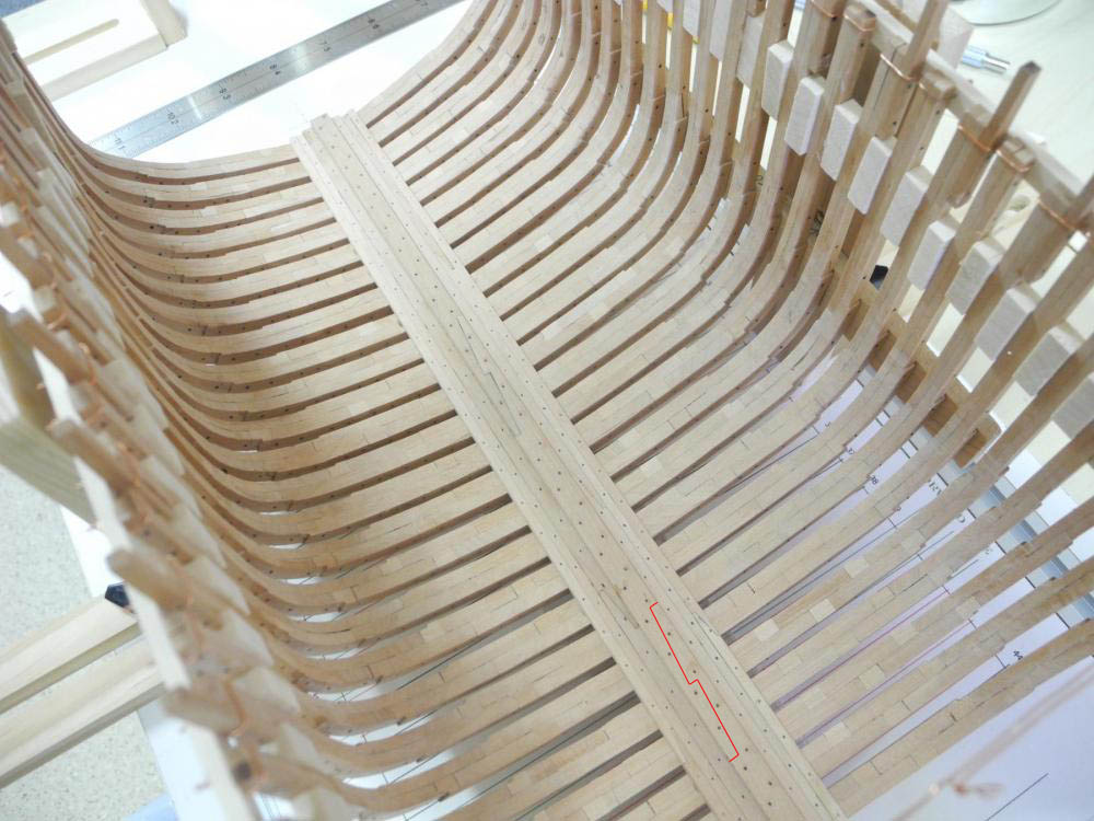
Yup, building one of these framed vessels is an education indeed!
-
Impressively researched and well modelled, Dick. Just catching up with your last few posts.
-
Pandora by marsalv - FINISHED - 1:52
druxey replied to marsalv's topic in - Build logs for subjects built 1751 - 1800
That is a lot of machining! Well done, Marsalv.