


druxey
-
Posts
13,090 -
Joined
-
Last visited
Reputation Activity
-

 druxey reacted to Siggi52 in HMS Dragon 1760 by Siggi52 - FINISHED - Scale 1:48 - English 74-Gun ship
Hello,
without much words, the knees are ready. It wasn't so bad as I first thought. Because I had not to dive so deep into the hull. From that point of view were the knees at the gun and upper gun deck the most worse things I had to do.
The next thing to do is to install the cannons with all there tackle.
Regards,
Siggi
-
druxey reacted to ChrisLBren in USF Confederacy by ChrisLBren - FINISHED - 3/16 Scale
Finger still hurts a bit a week later but my model related injury hasn't stopped me ! Finishing Confederacy by year end or bust.....
Update - the foremast channels are installed. I chose to paint Chucks nice boxwood deadeyes with Tamiya Flat Black paint. If I use paint/dye again on my next model (which Im leaning more to a "Belgian school" approach of all Pear) I will not bother with Fiebings dye - Tamiya flat black with an overcoat of Watcos Danish Oil looks as good as Fiebings with far less trouble in application.
This is may be my last build at this scale - thanks to a photo etch set from Model Expo Ive been able to realize the chainplate assemblies - soldering them this small would be a serious pain - kudos to you Rusty !
-
druxey reacted to Alex M in HMS Sphynx 1775 by Alex M - Scale 1/48 - English 20-Gun Frigate
Thank you guys for warm words! Druxey, you read my mind... I will fill the gaps with paint because it is too deep now, and I will make the "cement" a bit darker, as it is a bit too white.
Alex
-
 druxey got a reaction from mtaylor in HMS Sphynx 1775 by Alex M - Scale 1/48 - English 20-Gun Frigate
Beautiful, Alex. However, might I suggest toning down the color of the cement a little?
-
druxey reacted to Alex M in HMS Sphynx 1775 by Alex M - Scale 1/48 - English 20-Gun Frigate
Hi,
here the next update. I have made the base for the stove from 0,3mm wood strips, cut in squares. The first image show the cutting jig. Second image show some the "Stones" with a pencil line I mark before cutting, it's serve as direction guide by gluing. The "stones" are glued to 1mm plywood base.
To simulate the slate stone the plates are painted with diluted acrylic paint, then rubbed with pencil to give the surface "stone look"
Alex
-
druxey got a reaction from mtaylor in how to create rope of different thickness?
Three (or four) right hand lay ropes spun up left-handed will make a cable, not just thicker rope.
-
 druxey got a reaction from hornet in how to create rope of different thickness?
For really thin line, rather than use a two-strand (which never looks right), start with three thinner threads. If thinner thread isn't available, turn three-stranded thread in such a way as to un-spin it. You will find it consists of three yarns. Carefully pick up one yarn at one end with tweezers and cut it. Don't let the long end go! Now strip out this yarn, leaving two intact. Do this to the other two strands, then make up your line in the usual way.
On a planetary style ropewalk this technique may not be possible. I've only done this on a conventional style machine.
-
druxey reacted to NenadM in Using Adobe Ilustrator
Anybody use this program ?
To me, it is very useful, considering I do not have technical education, and do not know to work with any type of CAD programs
I have bit mapped Campbell`s *.pdf plans which I was forced to rescale, and then - lines get thicker, so plans in details become ... hmm ... dingy for use in workshop
In AI I put cropped bitmap from original plans rescaled to 100% as a first layer, and then draw over it, in separate layers, and get really clean "technical" drawing which can be used in workshop, with possibility to print every layer separately
MSW don`t allow to upload *.ai files, so here are two screenshots what I have got with AI
When you learn basic commands of AI, all process comes pretty fast
-
druxey reacted to Maury S in Echo by Maury S - FINISHED - Cross-Section
Thanks for the comments and the pictures. I spent time with ratios and fibonacci (Golden Ratio) proportions. Still unsure. Then I started laying out test strips (Bass Wood...not the good stuff) for the taper jig on the Byrnes saw and it just came together. The starting measurement was the 20" for the width of the two strakes. I started with 8" at the ends and 12" at the max. width. So I cut some sample planks to 12" (scale) (First mistake!) by 7" (actual) long. I copied the approximate long-side angle from Greg's TFFM III illustration at 2.5 degrees and cut a piece. The taper meant that the widest part (mid-strake) was not 12" anymore. Back and forth a couple of times on starting plank width and finally zeroed in on .325" (actual). I used my caliper set for 12" (scale) and slid it up the planks 'til I found the 12" width and marked it. That is the starting point for the short-side angle cut. Flipped them over, set the taper jig to 7.5 degrees (Greg's picture again) and made the second cut. All that was left was to set the caliper to 8" (Scale), slide it up the planks and I have the ends at 8". Total width now at 20". Good start. Now to line up the butts with frames. A smaller angle on the jig cuts will lengthen the spacing between the butts and I need to add about 1/16". I'll try 2 and 6 degrees. Greg, I'm going to paint the wales, but all of you and I will know they are done right! I probably will not darken the seams with the pencil this time though.
Maury
-
druxey got a reaction from mtaylor in Echo by Maury S - FINISHED - Cross-Section
Actually, after a while, those joints will 'read' through the paint or dye. Just give it time and seasonal wood movement!
-
 druxey got a reaction from Canute in How exactly does the rig for a hove-to maneuver look in the 18th ct ? (edited by admin)
I thoroughly recommend John Harland and Mark Myers' Seamanship in the Age of Sail. Get a copy! It shows every conceivable evolution that might be carried out by ships with various rigs. It's been out of print for years, but good copies are usually available on abebooks.com
-
druxey got a reaction from Canute in Echo by Maury S - FINISHED - Cross-Section
Actually, after a while, those joints will 'read' through the paint or dye. Just give it time and seasonal wood movement!
-
 druxey got a reaction from GaryKap in How exactly does the rig for a hove-to maneuver look in the 18th ct ? (edited by admin)
I thoroughly recommend John Harland and Mark Myers' Seamanship in the Age of Sail. Get a copy! It shows every conceivable evolution that might be carried out by ships with various rigs. It's been out of print for years, but good copies are usually available on abebooks.com
-
druxey reacted to dvm27 in Echo by Maury S - FINISHED - Cross-Section
I used the top and butt method of anchor stock planking. The combined two lower strakes of the main wale are 20" wide. I used 12" for the thickest part and 8" for the thinnest part. I used 20' for the length of the plank with a 14' and 6' section. Once you lay this out on paper the angles are set. It's very easy to cut these using the taper jig on the Byrnes table saw. If you are planning to paint or dye the wales you may wish to forgo this and just use plain strakes. As you'll see in the photo my meticulous top and butt joinery is not visible after sanding and staining.
One last point - the "black" strake may be either blackened or not.
-
 druxey got a reaction from allanyed in Super fine saw from Japan
The illustration is of one of the famous 18th century Kabuki theater actors, Otani Oniji II, by the woodcut artist Toshusai Sharaku.
-
druxey reacted to jhearl in how to create rope of different thickness?
I use different sizes and quantities of threads to make different sizes of ropes. I prefer DMC crochet thread - http://www.dmc-usa.com/Products/Needlework-Threads/Crochet-Threads/Cordonnet.aspx
I might use 3, 6, or even 9 threads to make a rope. When I was first figuring it all out, I made a bunch of ropes of varying sizes then kept a sample of each with details of their thread size and count so I could reproduce them as needed.
Cheers -
John
-
druxey reacted to cabrapente in Le Francois by cabrapente
Hello Michel. I'm doing a 1 / 48.francoise
progress of the day
-
druxey reacted to Cristiano in What is "entry level" in the world of Wooden Ship Building? - moved by moderator
Almost all of my thoughs are already included in previous other answers, so I will not repeat something that has been already said.
In anycase, if someone want to approach the wooden ships world for the first time, should start absolutely with simple small kits and with a lot of humbleness, since wood sometimes is not so a "smart material" to be managed.
The world is full (and ebay too!!) of big (and costly) ships started by newbies and never finished, due to their willingness collapsed in front of contructions problems never seen before.
-
 druxey got a reaction from dvm27 in how to create rope of different thickness?
For really thin line, rather than use a two-strand (which never looks right), start with three thinner threads. If thinner thread isn't available, turn three-stranded thread in such a way as to un-spin it. You will find it consists of three yarns. Carefully pick up one yarn at one end with tweezers and cut it. Don't let the long end go! Now strip out this yarn, leaving two intact. Do this to the other two strands, then make up your line in the usual way.
On a planetary style ropewalk this technique may not be possible. I've only done this on a conventional style machine.
-
 druxey got a reaction from alangr4 in Super fine saw from Japan
The illustration is of one of the famous 18th century Kabuki theater actors, Otani Oniji II, by the woodcut artist Toshusai Sharaku.
-
druxey reacted to EdT in Young America 1853 by EdT - FINISHED - 1:96 - POB - extreme clipper
Young America 1853 – POB 1:96
Part 20 – Knightheads
The knightheads reinforced the stem on either side and provided a base for securing the hawse timbers that formed the forward hull back to the first cant frames. This detail is shown in the posts for the full framed version of the model. Rising above the top of the sides, the knightheads also provided lateral support to the bowsprit. To accommodate the 36” square section of the bowsprit, additional space was provided between knightheads by additional members, 10” thick stem timbers, bolted to the sides of the stem assembly. The two 10” stem timbers astride the 16” thick stem provided the necessary 36” spacing for the bowsprit.
On the POB model only the upper parts of the knightheads and stem timbers were modeled. In the first picture their patterns have been pasted to the correct size stock.
As with all of the stock for this demonstration model, ¾” wood was used, allowing all the thicknesses to be cut on a good model circular saw. This was done to allow the model to be made from readily available stock without the need for a thickness sander/planer – a rather expensive tool and not one that beginning scratch builders might have. In the next picture the members have been cut out and given an initial bevel based on the pattern lines.
These were cut from hard maple. The knightheads will be exposed on the model but painted black. The members to the right are shown in their relative positions. In the next picture the starboard head timber is being fitted into the space between the stem and the most forward bulkhead.
To prepare for this, the pine spacers forward of the first bulkhead were removed by sawing and paring with a straight chisel. These spacers had been installed to protect the forward bulkhead during initial rough fairing of the hull.
In the next picture the breadth across the installed head timbers is being checked for the eventual fit of the bowsprit.
At 1:96 the breadth needs to be 3/8”. This precise breadth was obtained by sanding the sides of the members after they were glued in. In the next picture the port knighthead is being glued into place.
With both knightheads firmly secured they could be faired into the stem rabbet. In the next picture a gouge is being used for this.
With the shape roughed out with the gouge, a curved rasp was used to refine it – as shown below - followed by 120-grit sandpaper.
With the knightheads in place and faired, the topside planking could begin.
Ed
-
druxey reacted to Senior ole salt in Has anyone come out with a kit of the James Caird (edited by admin)
It's a shame no has done a model or kit of this boat. However I did a painting of her skirting S. Georgia island.
The boat is on a back of a wave as they seek a possible landing place.
SOS
-
druxey reacted to jack.aubrey in HMS Guadeloupe by jack.aubrey - 1:48 scale - ex French Le Nisus - Brick de 24
Hi Apollo,
don't worry to go off topic in this thread, in this period I've nothing to show, so I like to discuss about ships rather than being idle . .
The following four images show the Prince Royal model presented in the book "1st Rate....". It isn't a contemporary model, there is nothing contemporary. This model is of 1991 made by Peter, Basil Grenville in Pinner, Middlesex, UK.
Scale: 1:48.
It's a full hull model of the 55-gun three-decker ‘Prince Royal’ (circa 1610), built plank on frame in the Navy Board style.
The model is equipped, fully rigged with a highly decorated hull, nearly all of which is based on the fine contemporary painting of her by the Dutch artist Adam Willaerts (see BHC0266 and BHC0267). Designed and built by the well-known shipwright Phineas Pett, the ‘Prince Royal’ was floated out of the building dock at Woolwich on 25 September 1610, and had the distinction of being the first three-decker in the Royal Navy.
It was common practice during the 17th century for major warships of this size to undergo several repairs during their careers and this ship in its last configuration had a gun deck measuring 160 feet in length and was capable of mounting up to 90 guns in total. It was not until her 40th year, under her Commonwealth name ‘Resolution’ that she saw action engaging successfully at the battles of Kentish Knock, North Foreland and Scheveningen, during the First Anglo-Dutch War (1652–54). During the reign of Charles II, she survived the Battle of Lowestoft in 1665, but during the Four Day’s Battle, 1–4 June 1666, she ran aground and was captured and subsequently burnt by the Dutch.
Regarding the German forum, I reviewed it and it's impressive. I have no idea about his sources on the ship but I suggest you to try to communicate with the modeler and get some answers. It seems well introduced . .
Regarding SOTS the sources belong after its construction but the majority of them try to refer to her in the first years of her life. There is also a model in the NMM from Robert Seppings, Surveyor of the Navy in the first years of 1800 trying to reproduce it . . in its original shape.
Friendliness, Jack.
-
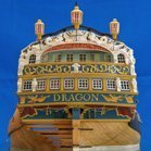 druxey got a reaction from Siggi52 in HMS Dragon 1760 by Siggi52 - FINISHED - Scale 1:48 - English 74-Gun ship
Nicely done, Siggi!
-
druxey reacted to Dan Vadas in Super fine saw from Japan
Further to Al's post above, check out THIS blade. 120 teeth per inch - WOW . They also have coarser blades and holders/handles.
Danny