HOLIDAY DONATION DRIVE - SUPPORT MSW - DO YOUR PART TO KEEP THIS GREAT FORUM GOING! (Only 13 donations so far - C'mon guys!)
×

.jpg.f26acc9a74319261612561bfa7da1303.jpg)
vaddoc
-
Posts
1,601 -
Joined
-
Last visited
Content Type
Profiles
Forums
Gallery
Events
Everything posted by vaddoc
-
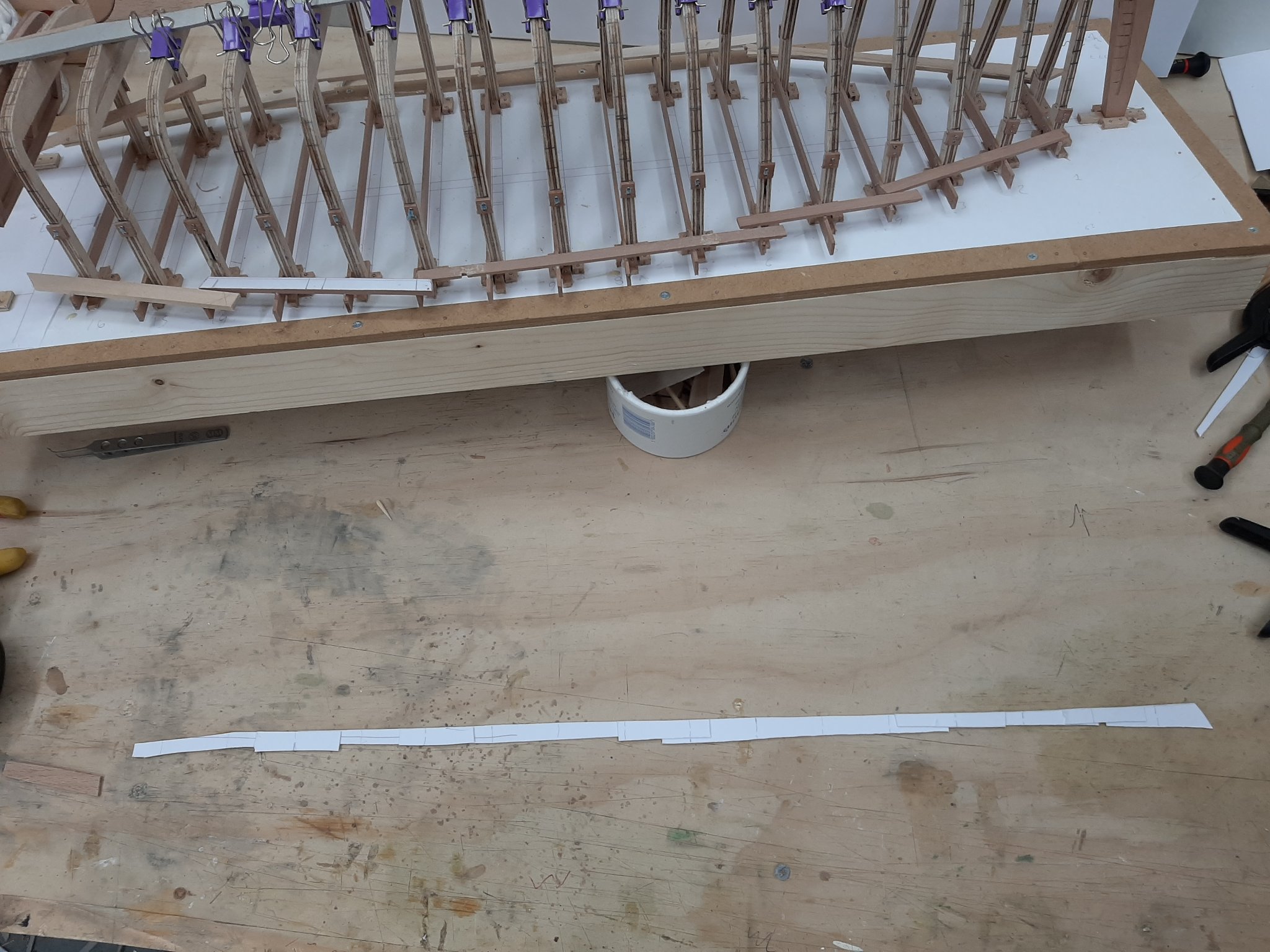
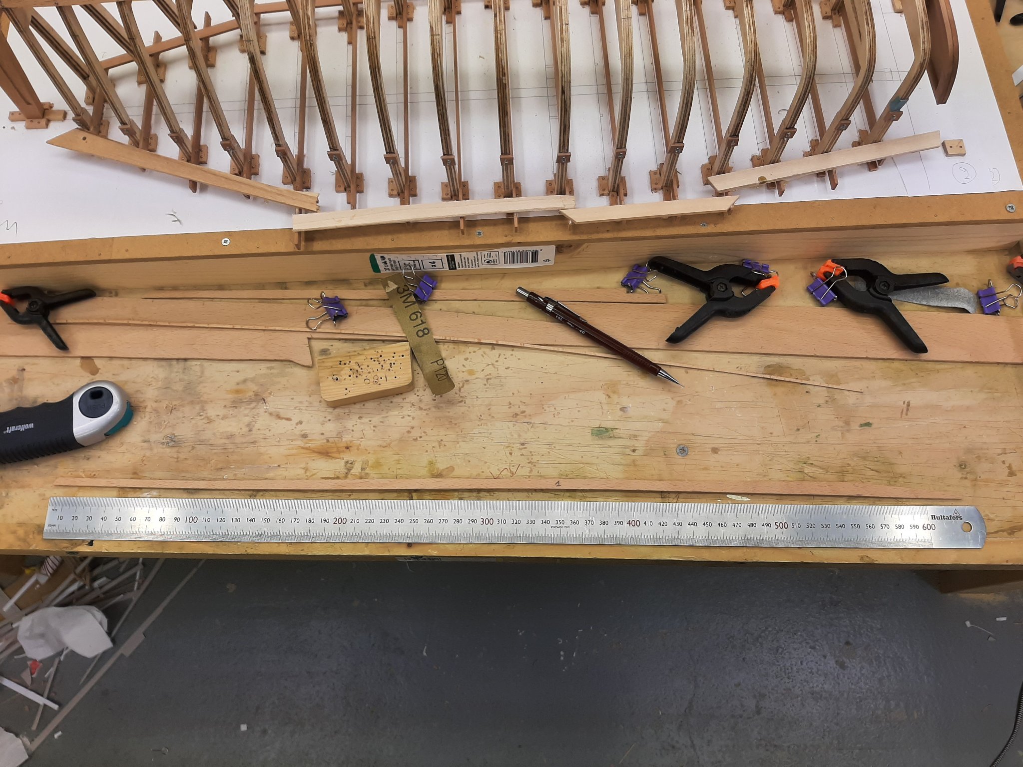
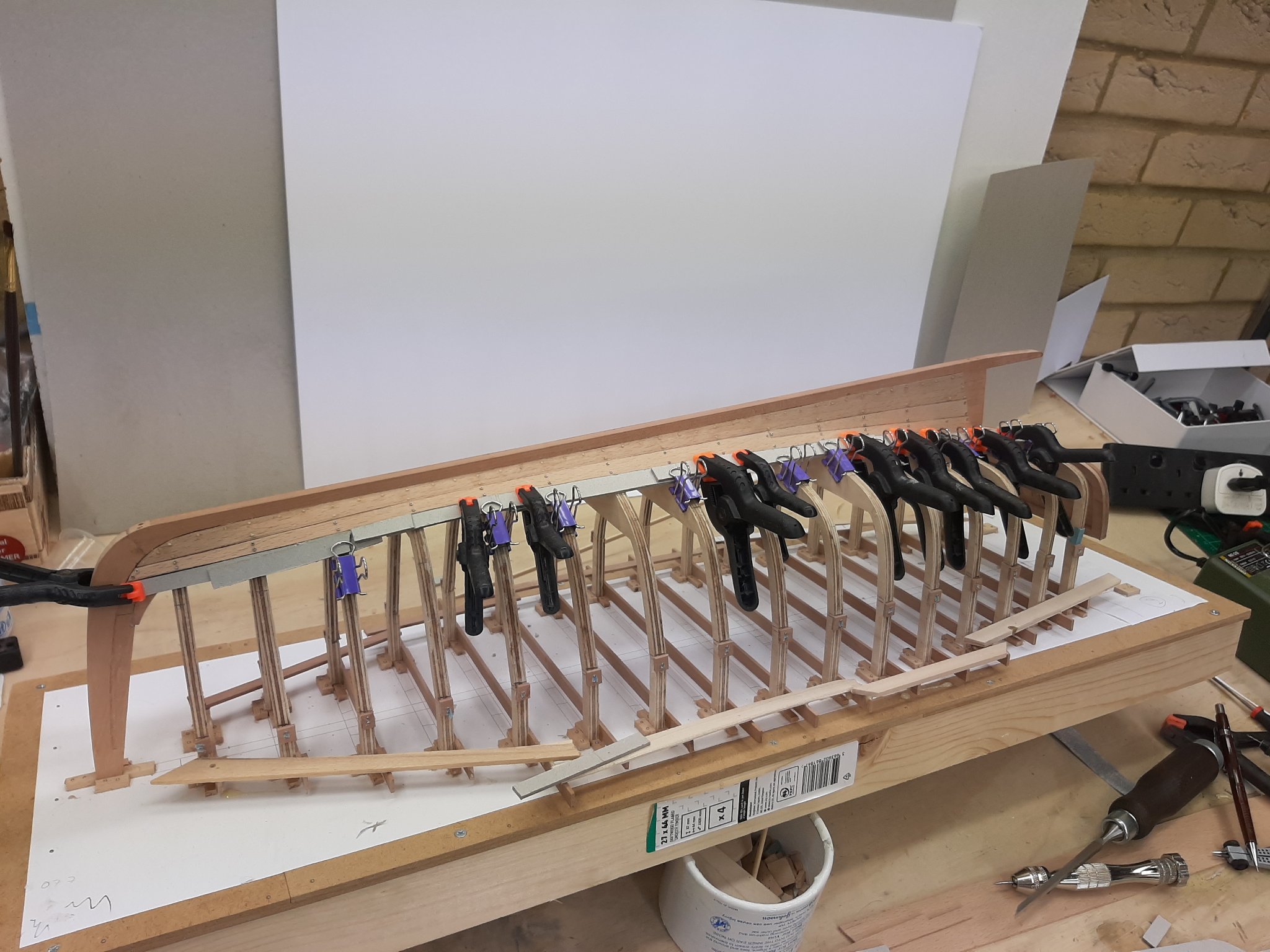
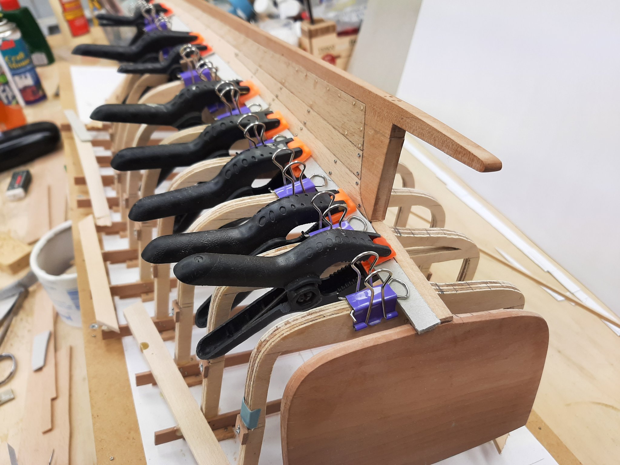
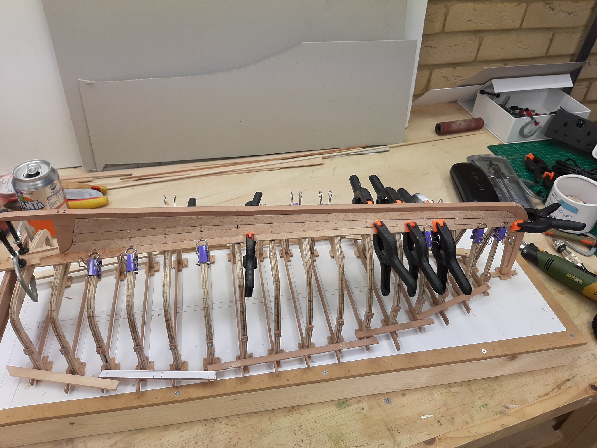
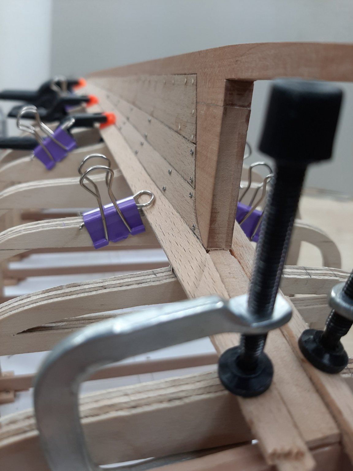
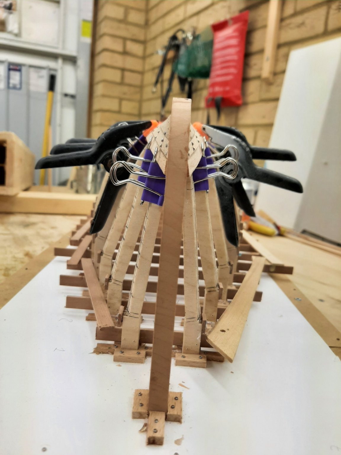
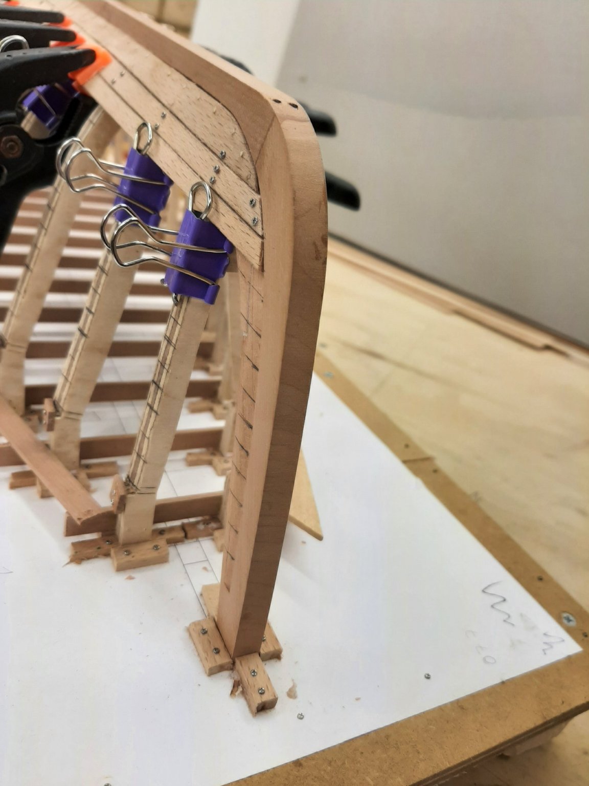
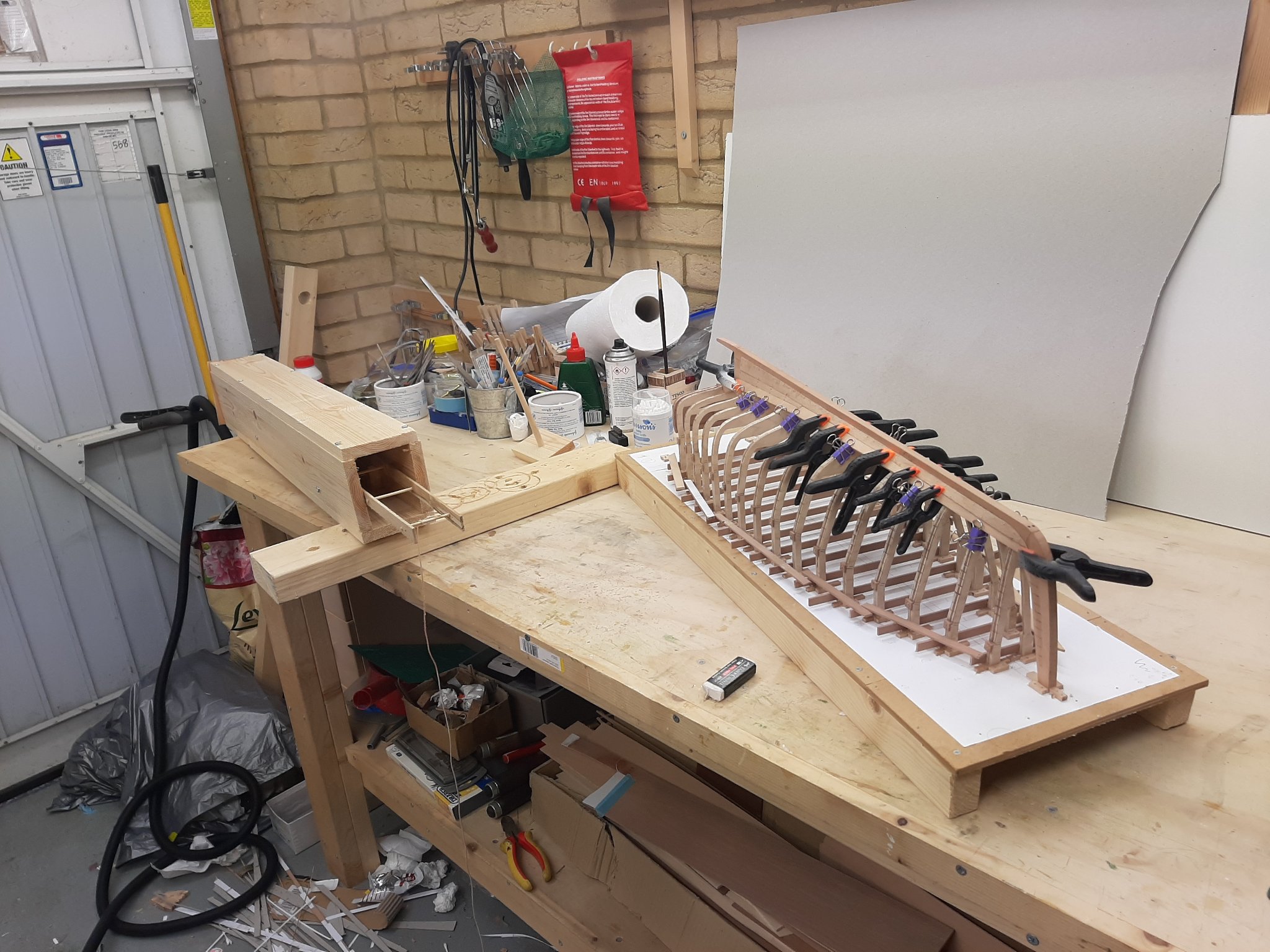
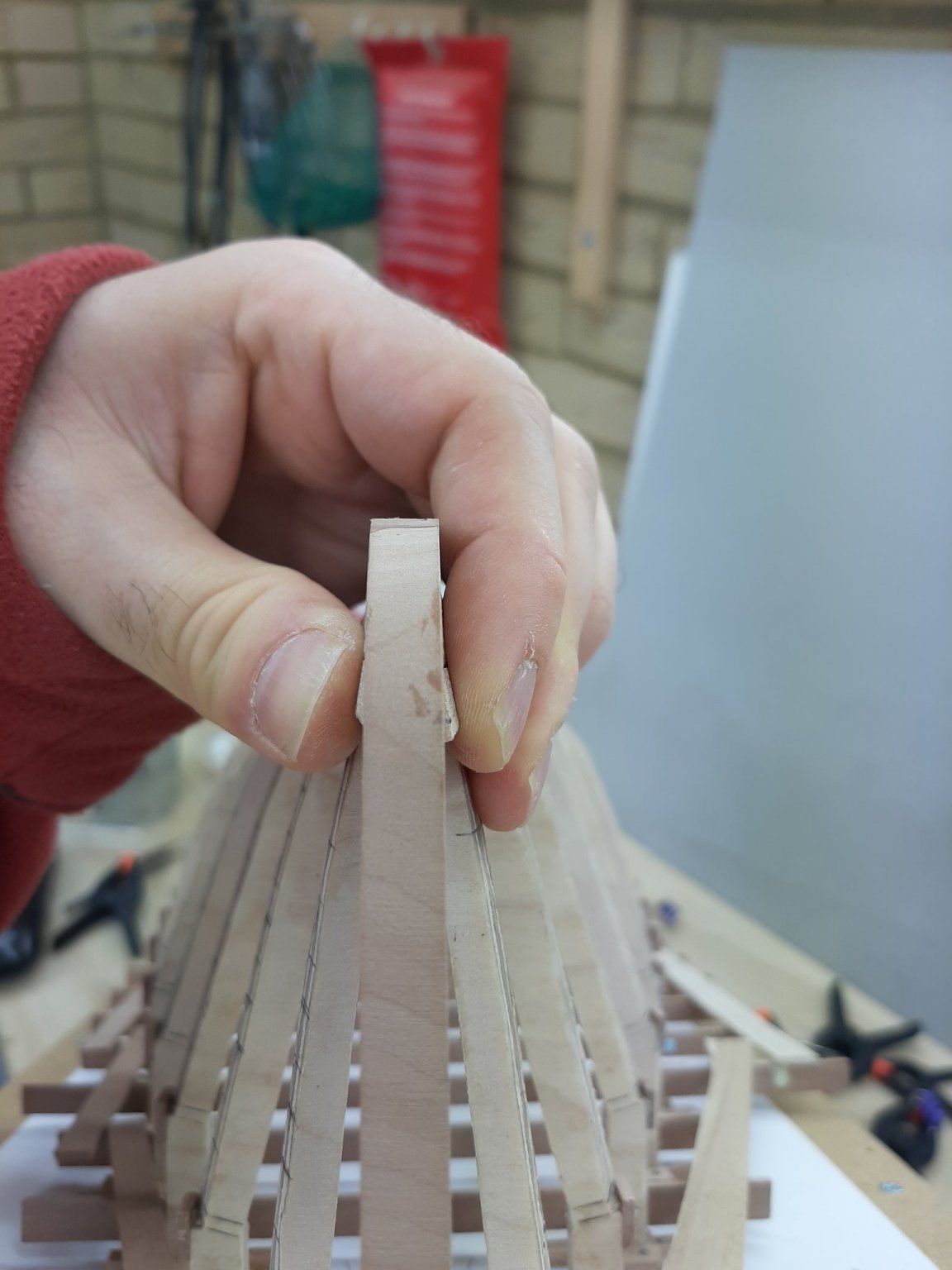
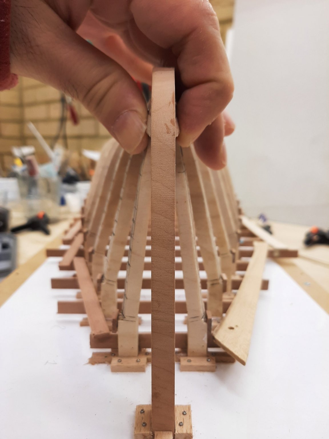
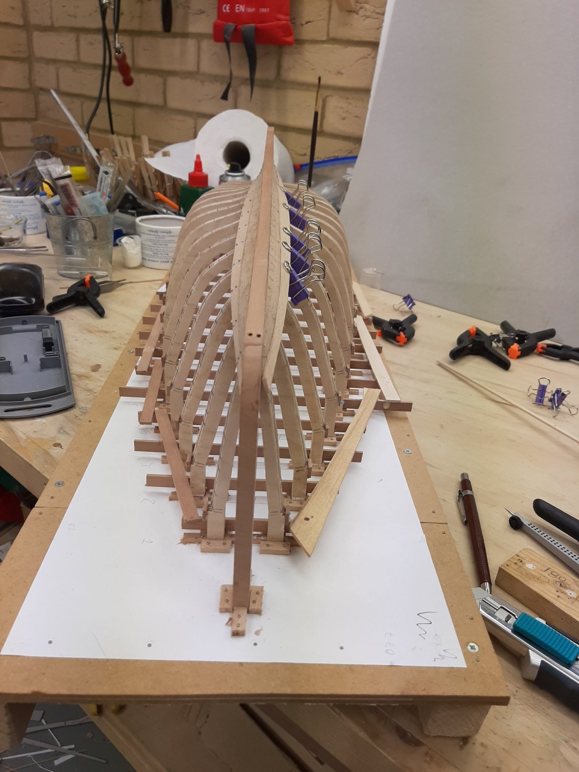
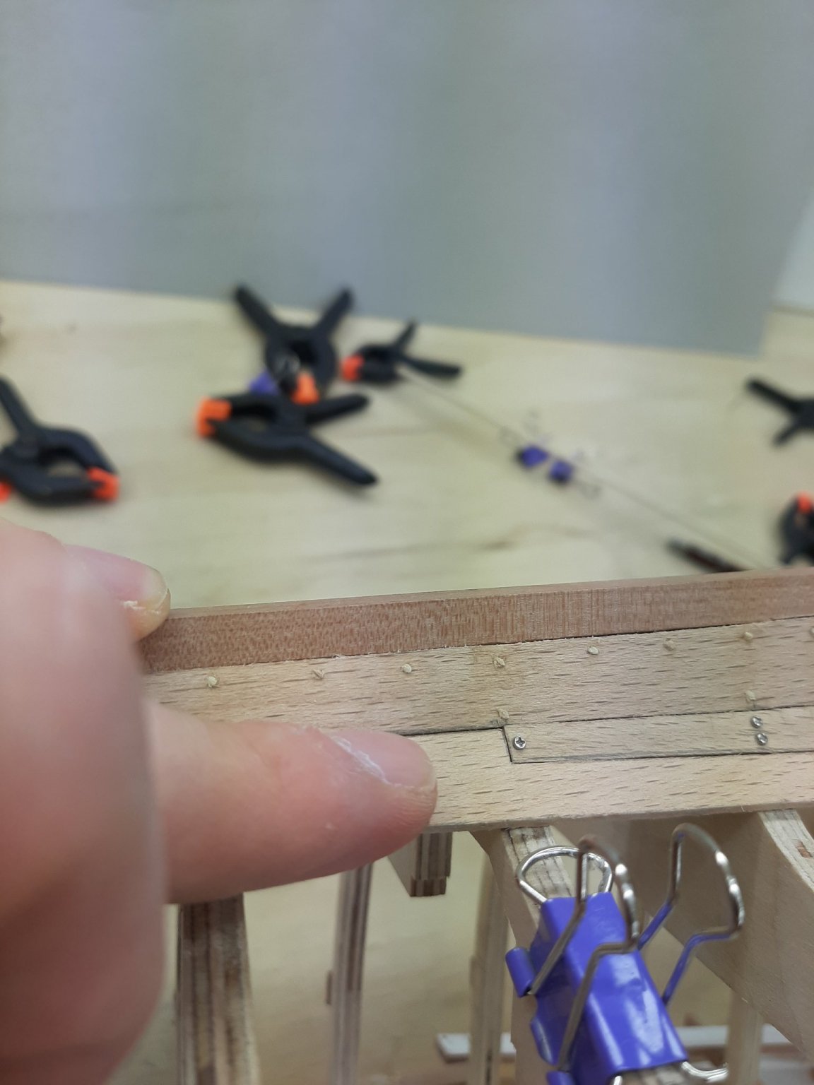
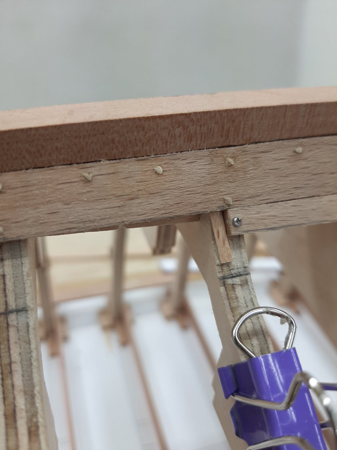
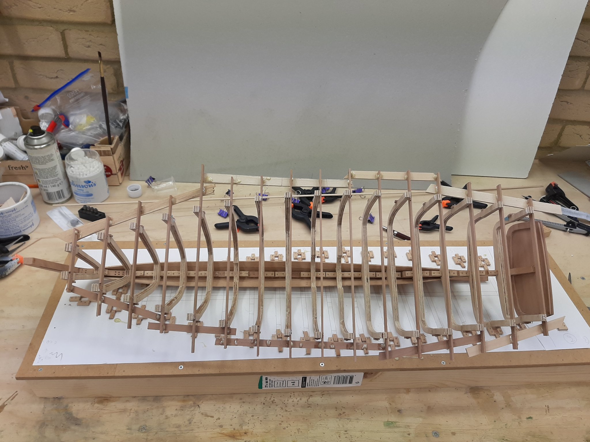
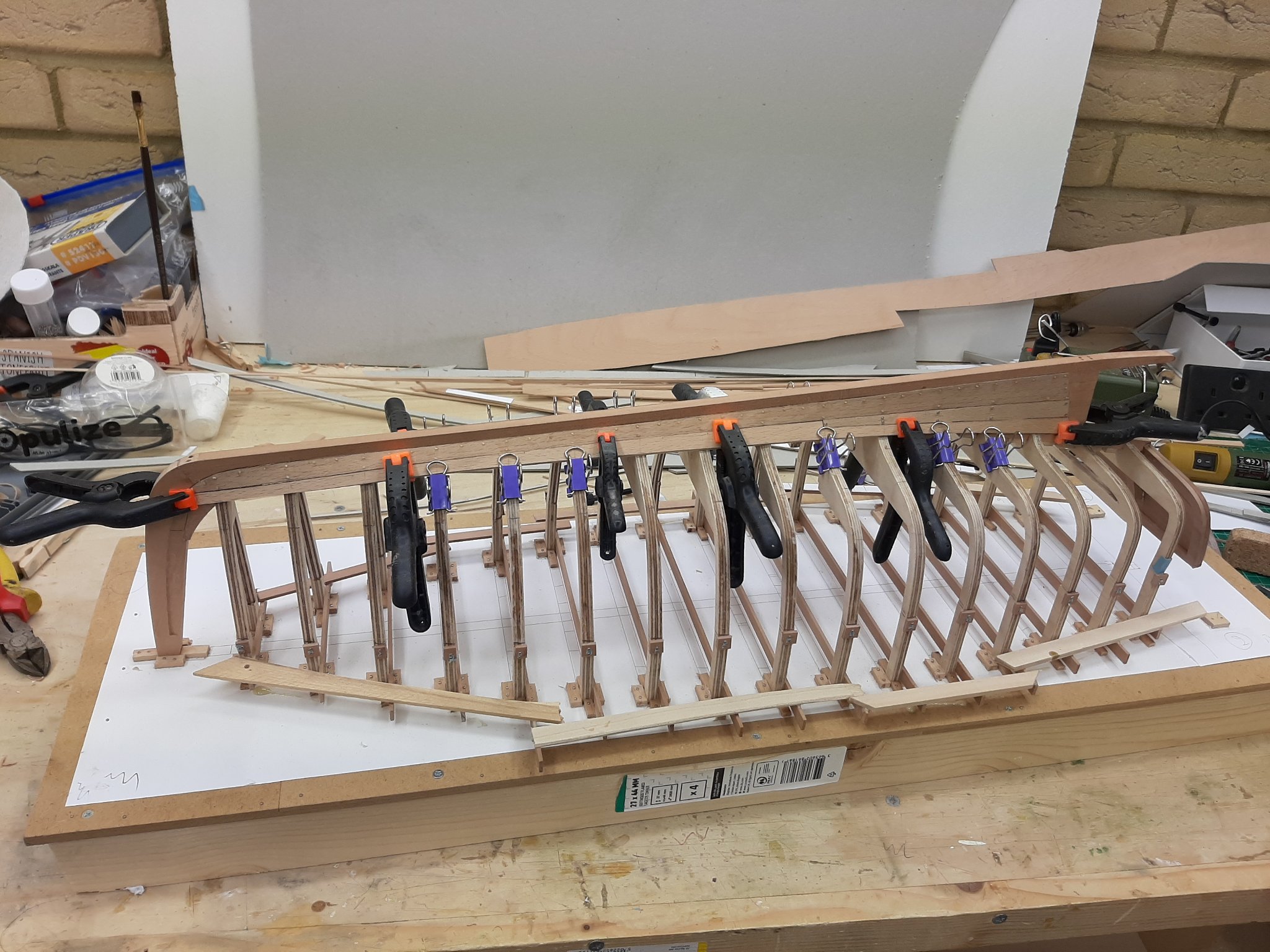
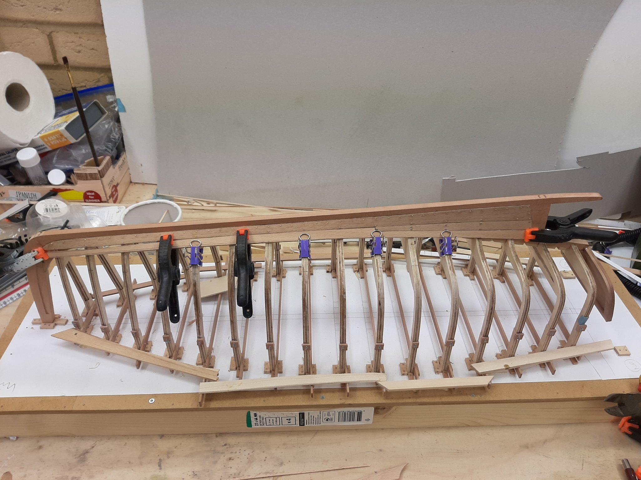
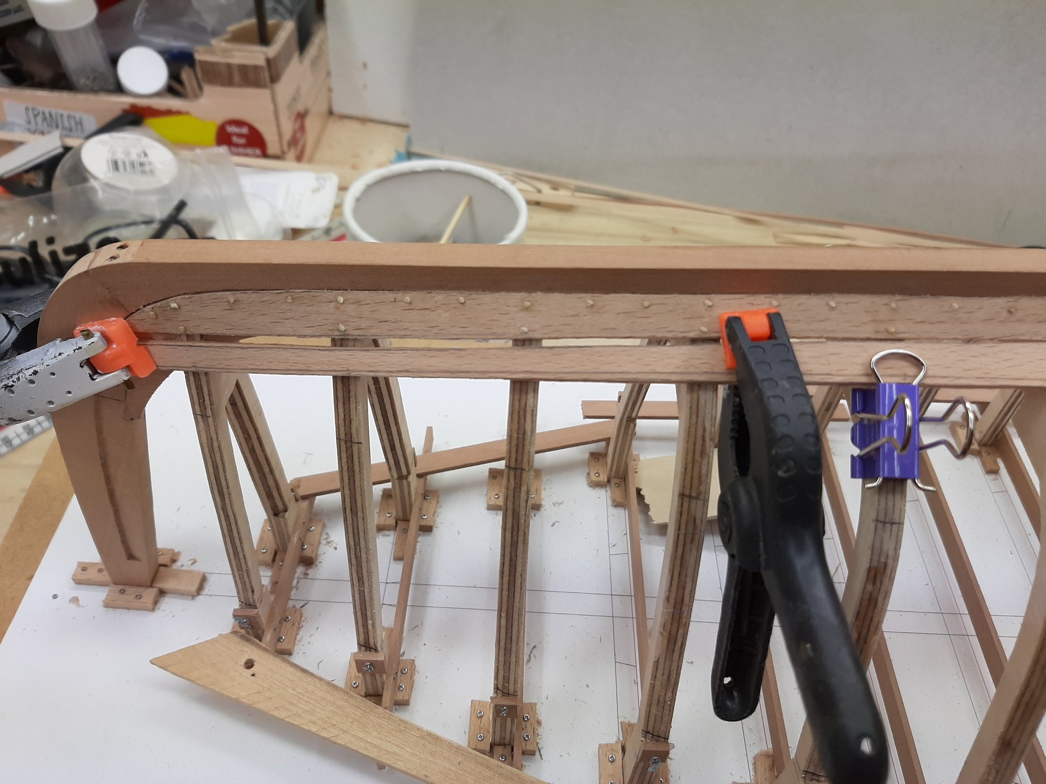
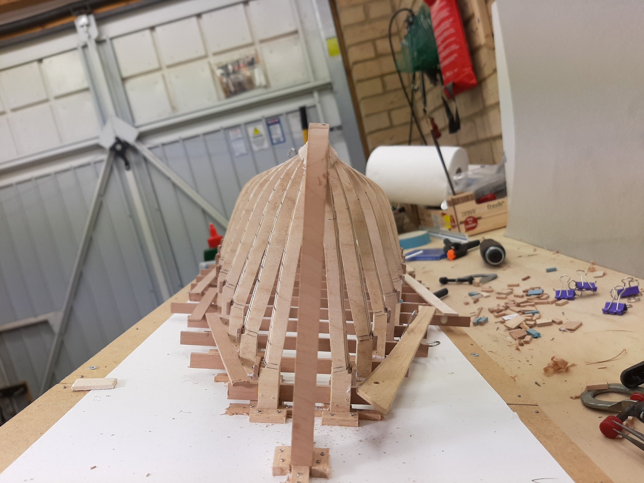
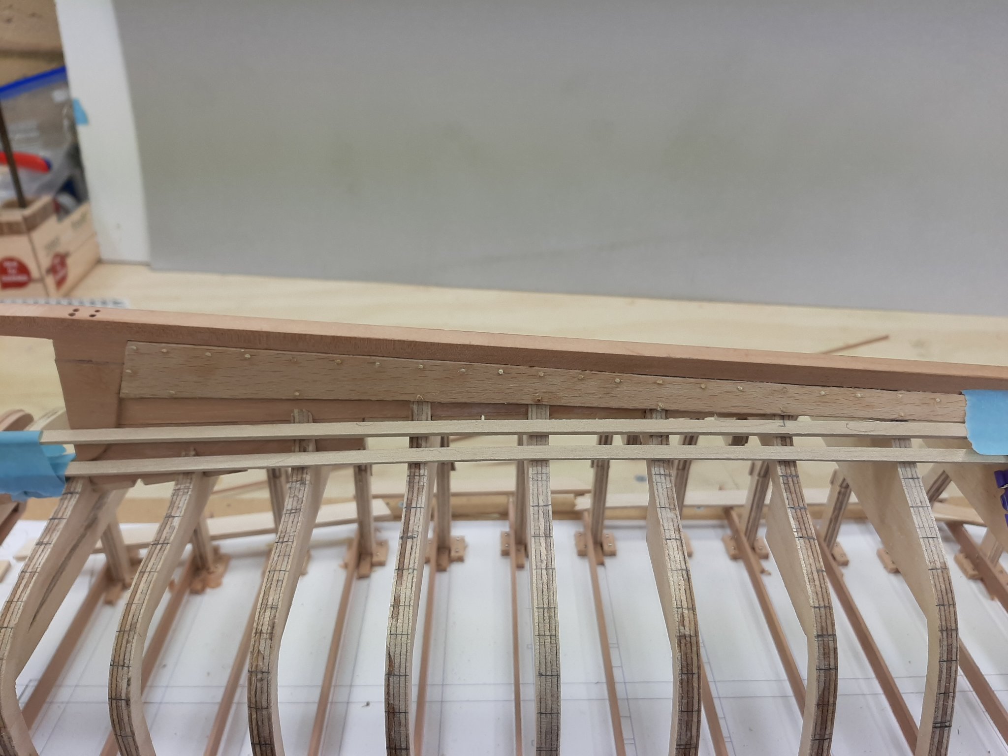
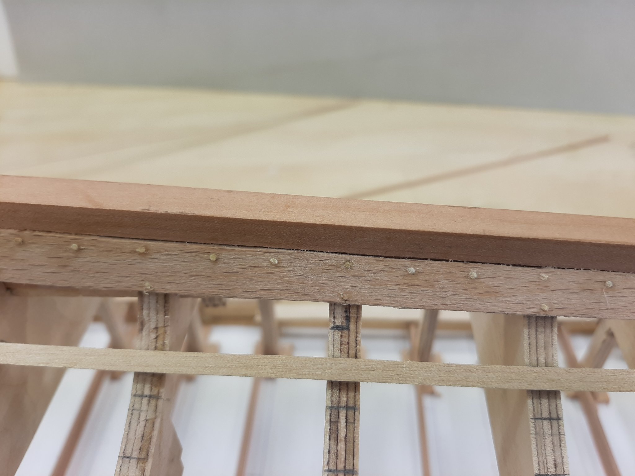
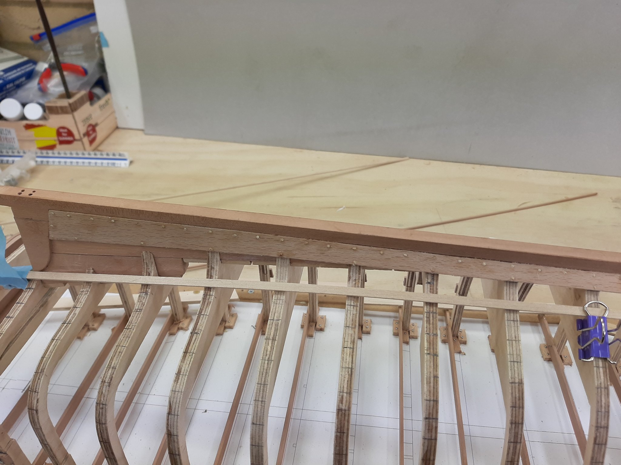
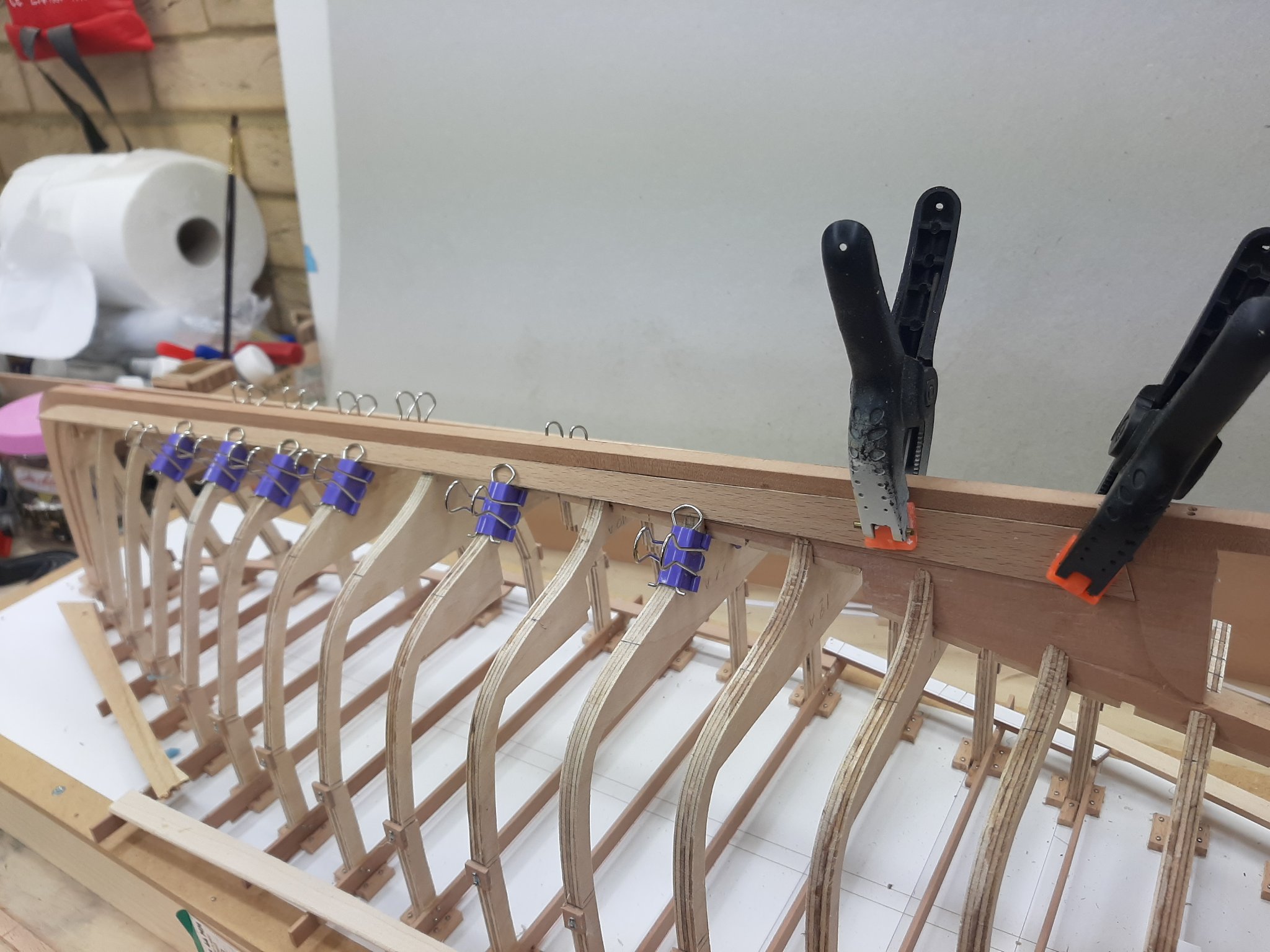
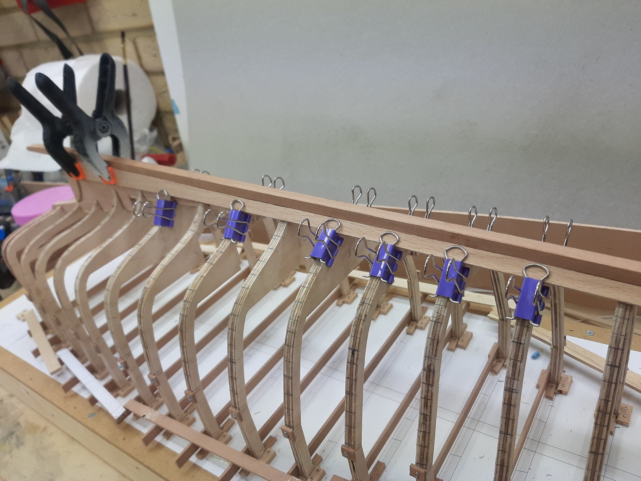
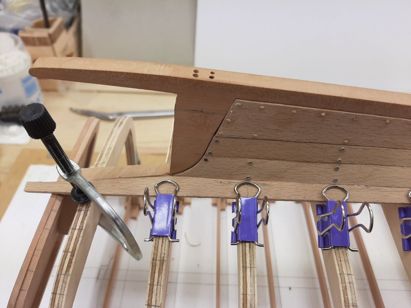
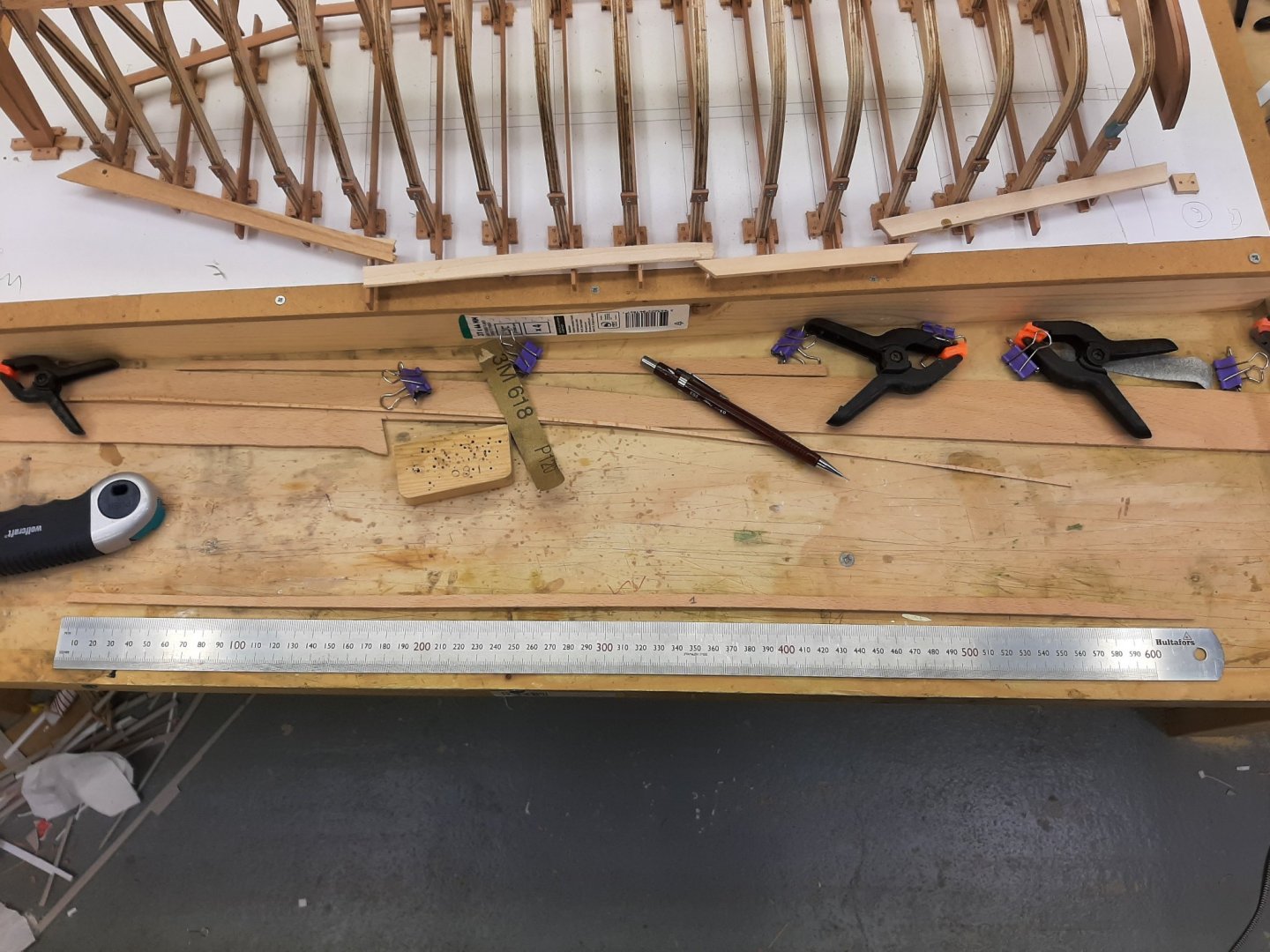
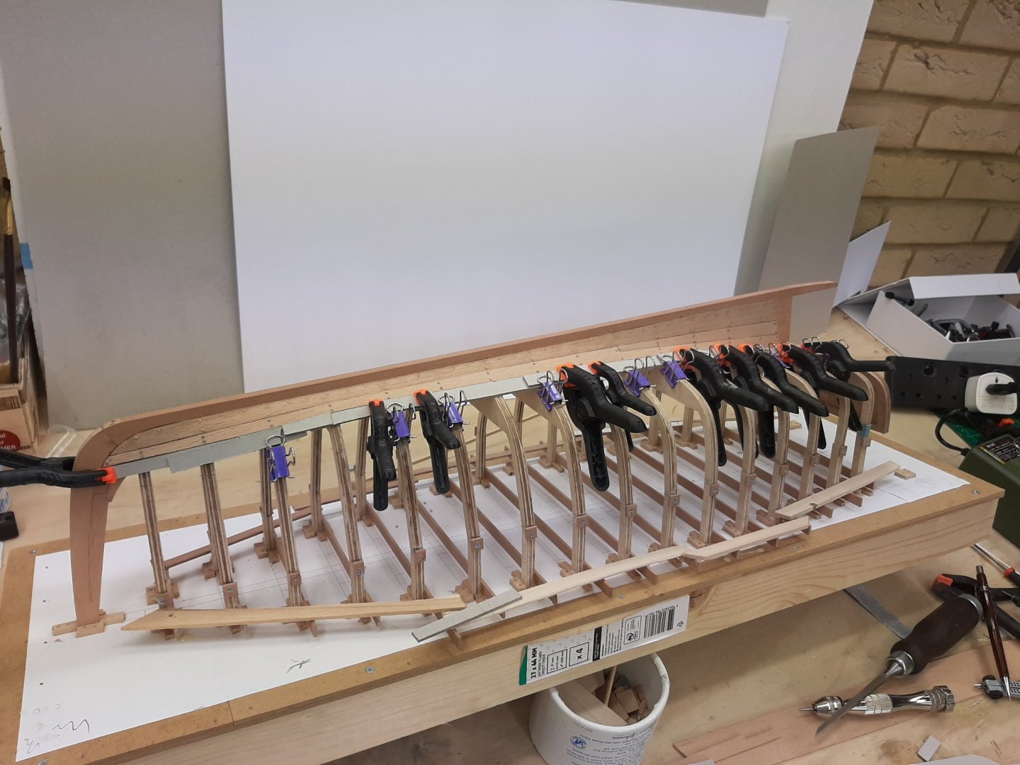
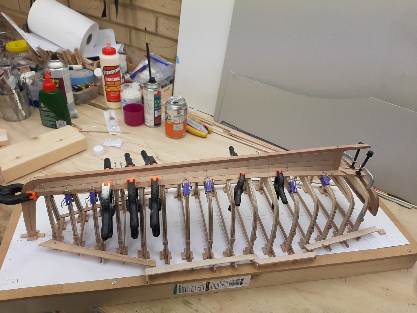
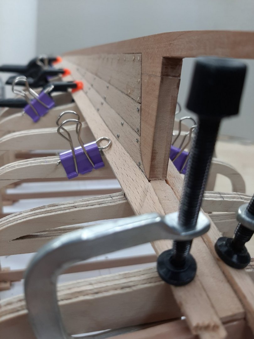
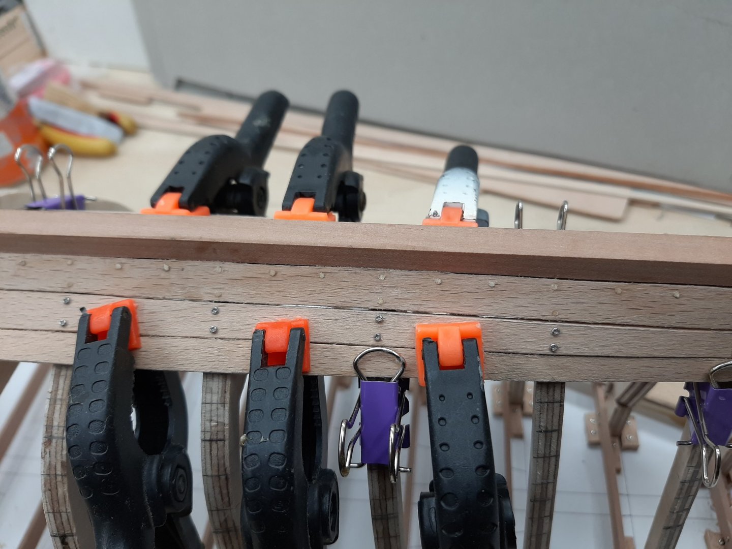
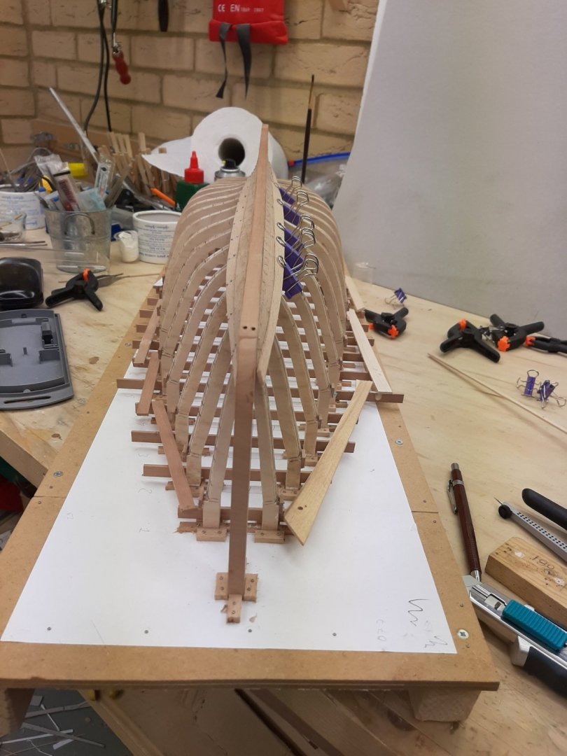
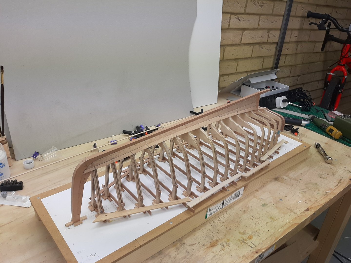
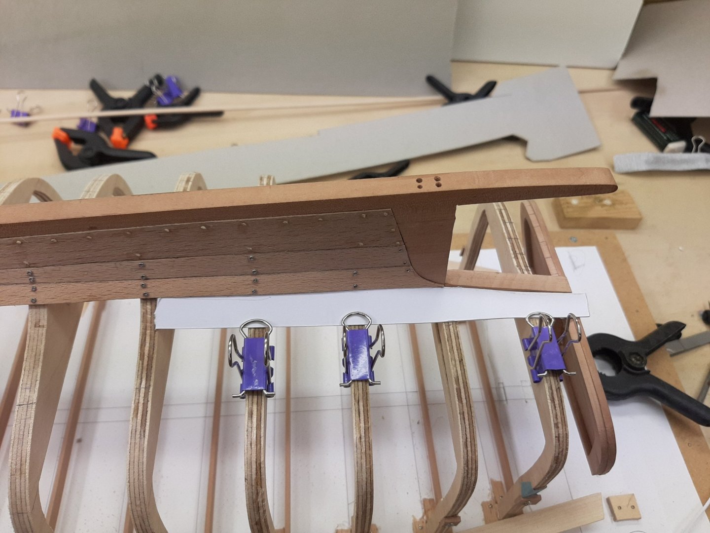
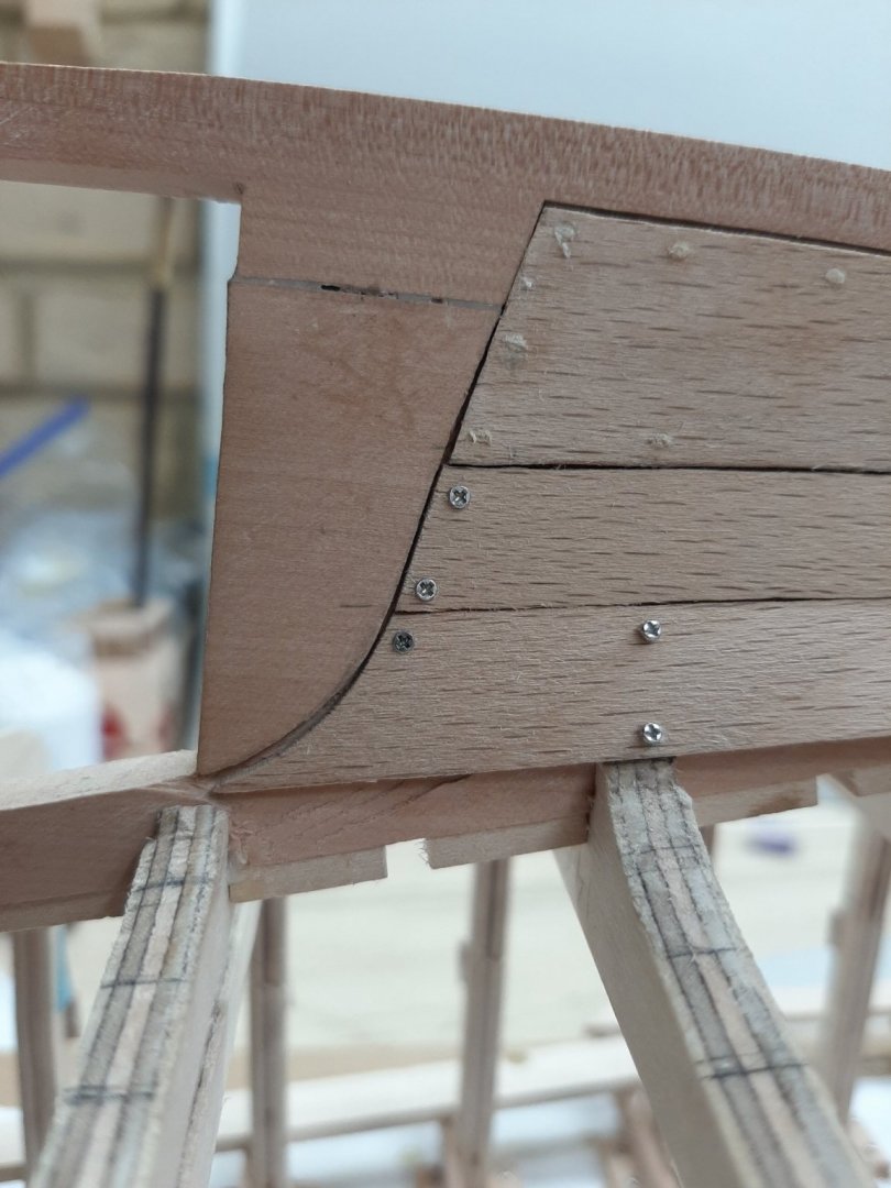
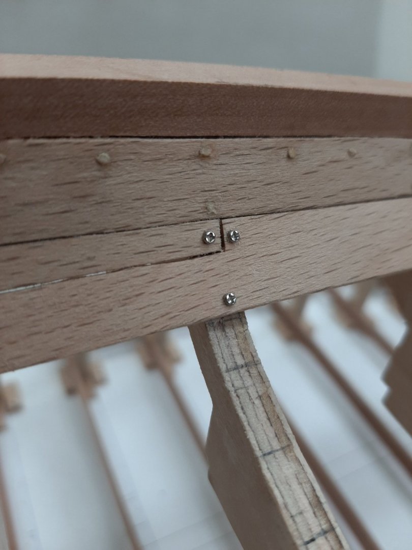
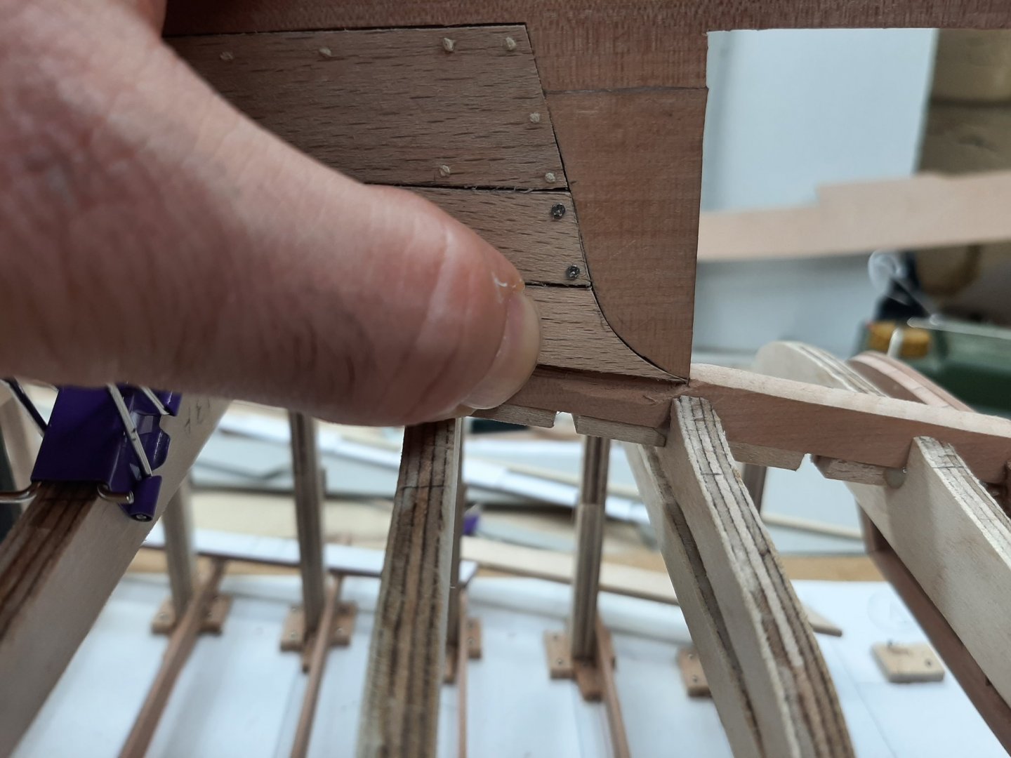
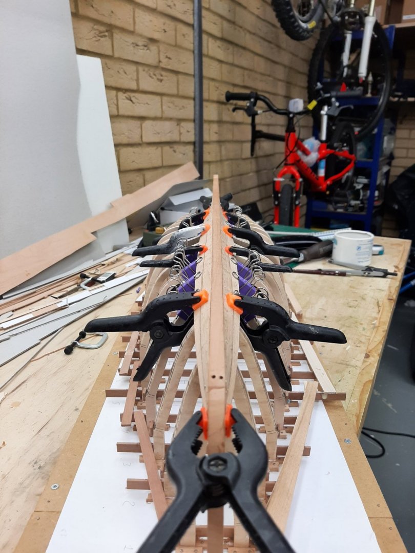
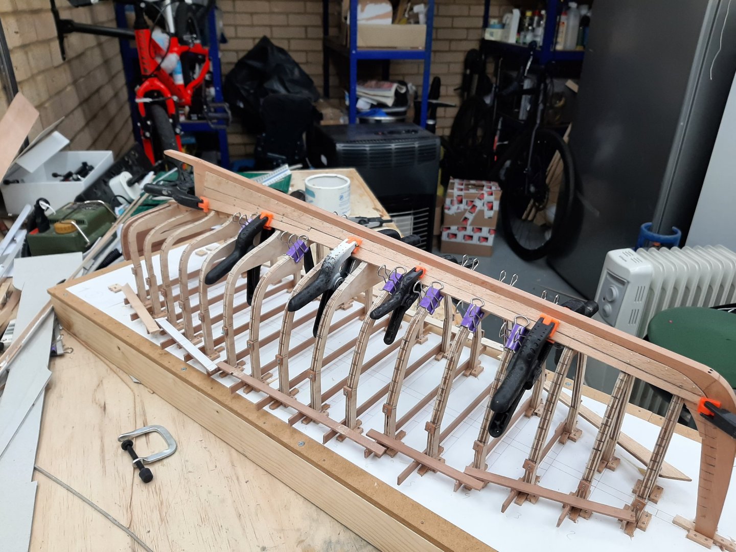
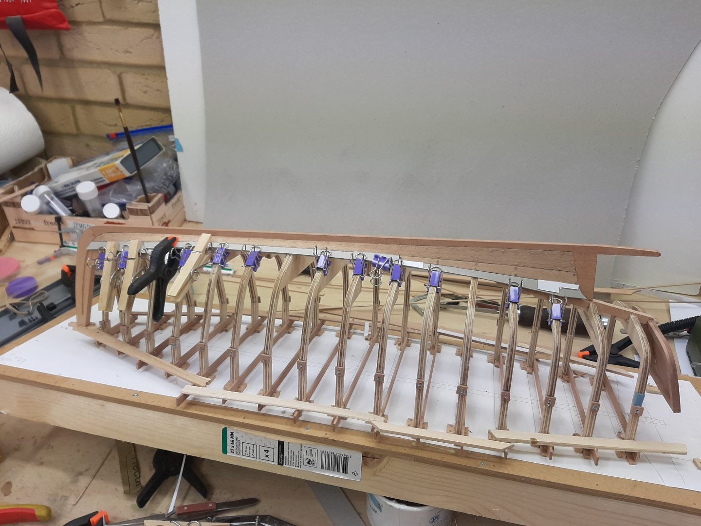
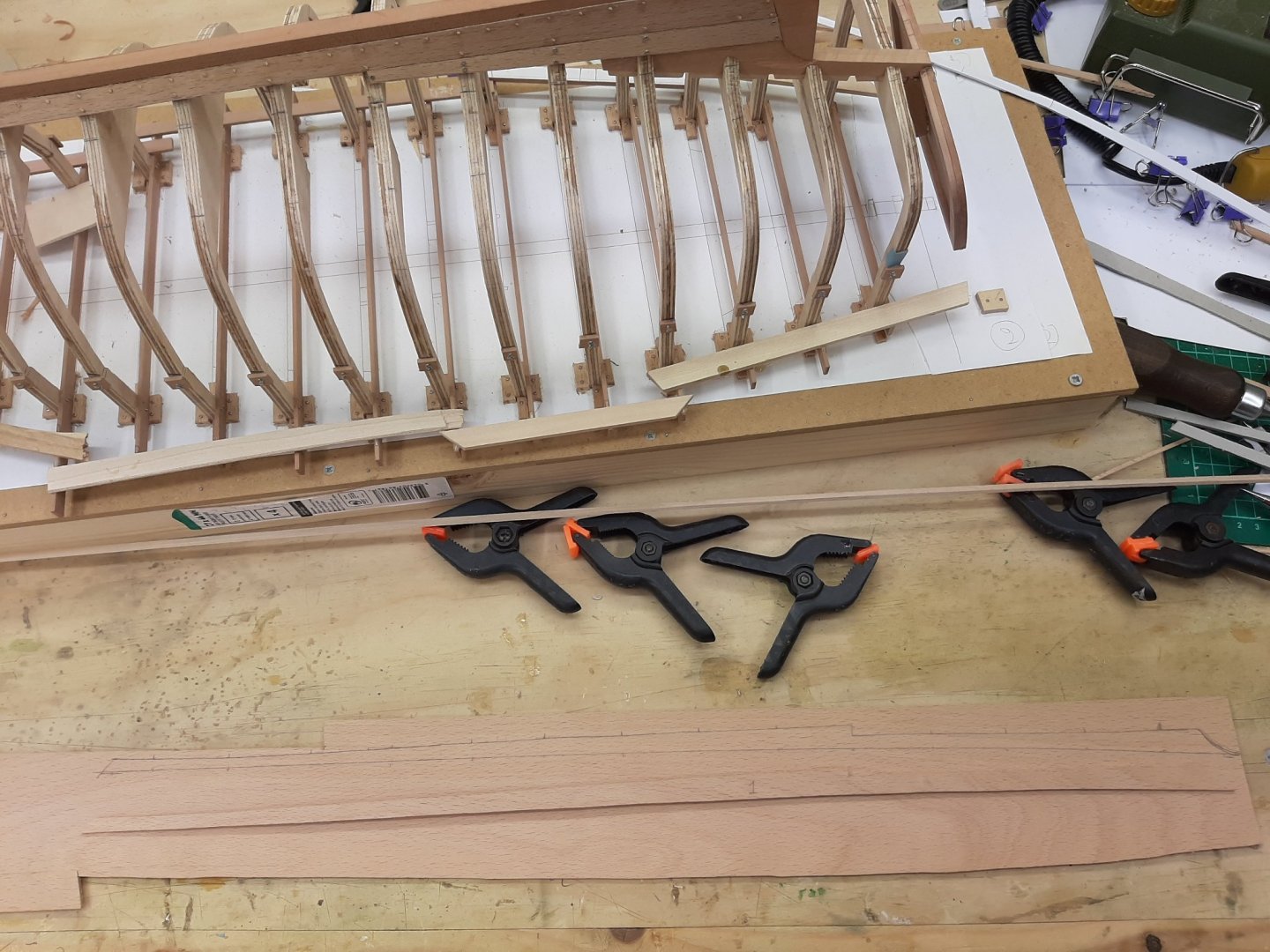
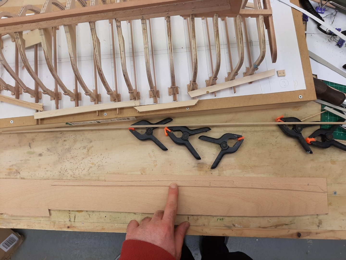
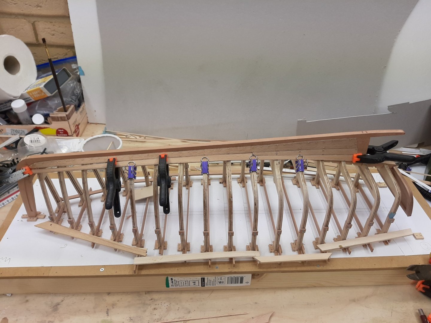
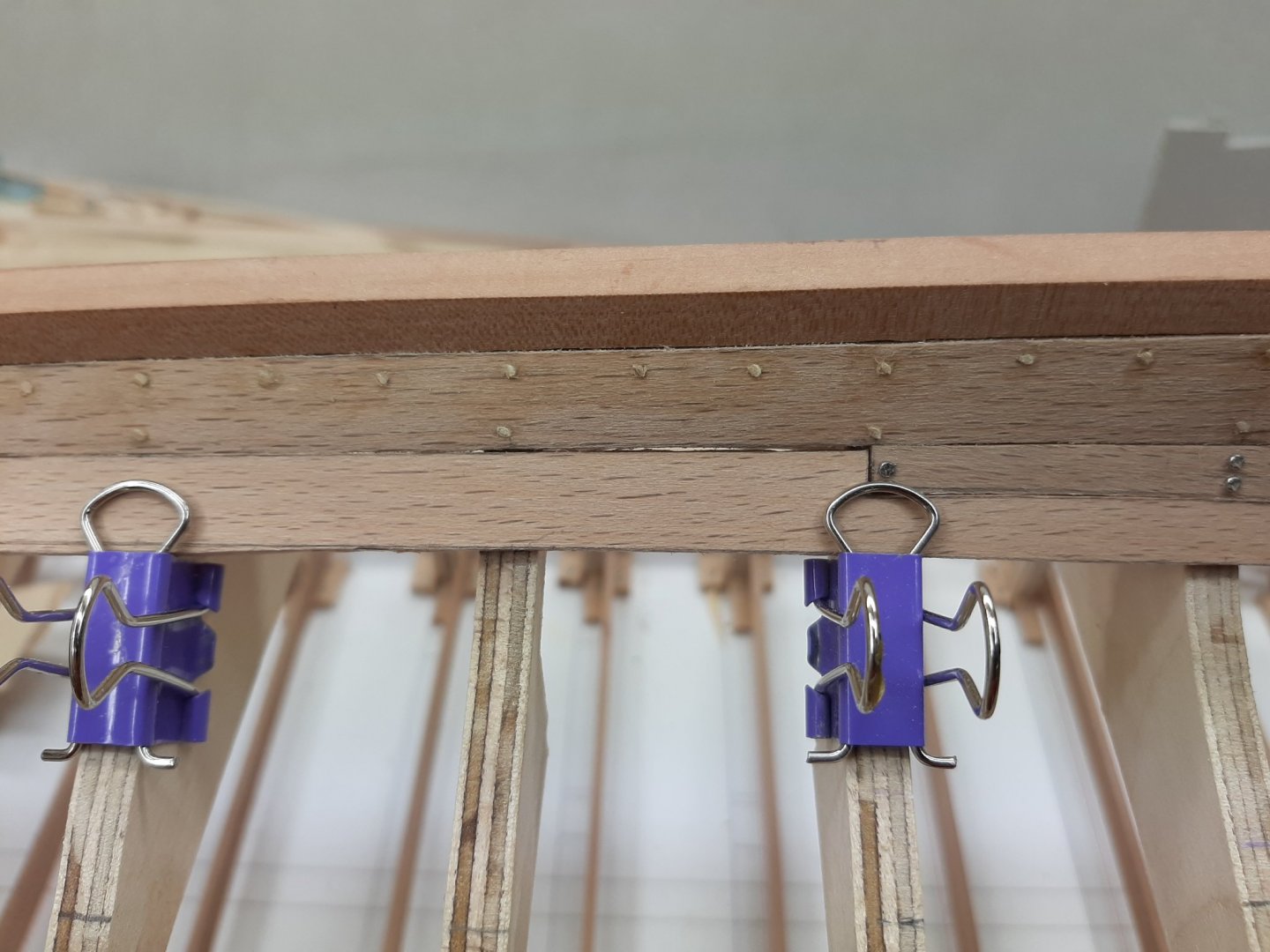
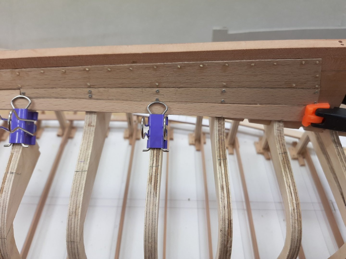
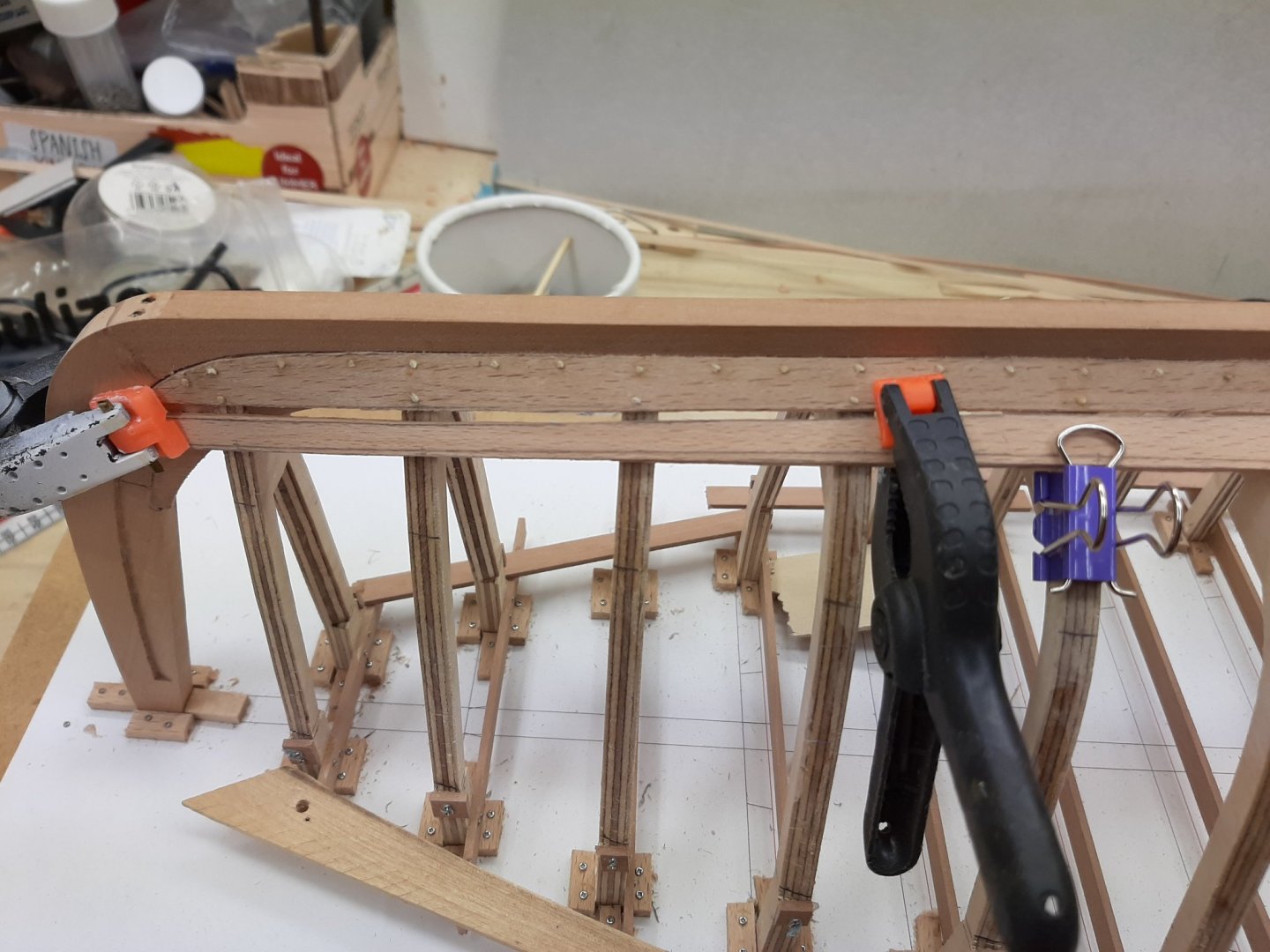
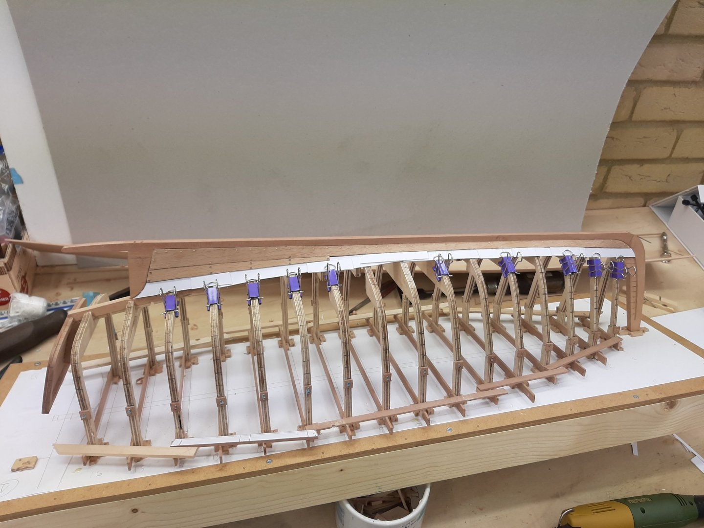
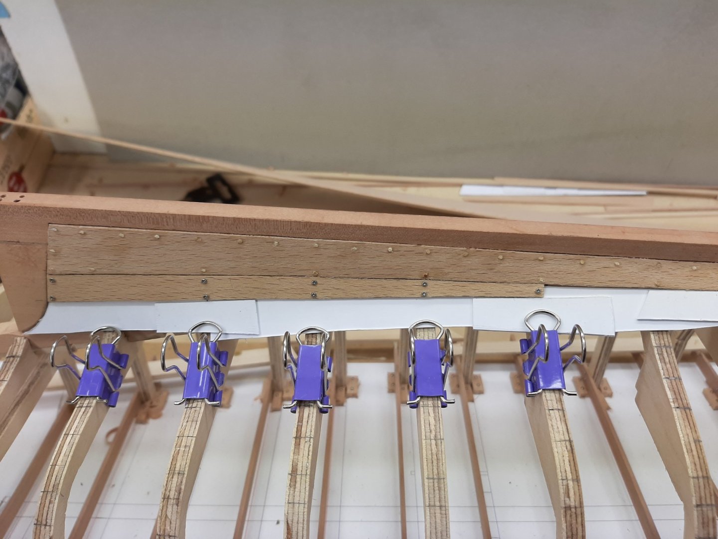
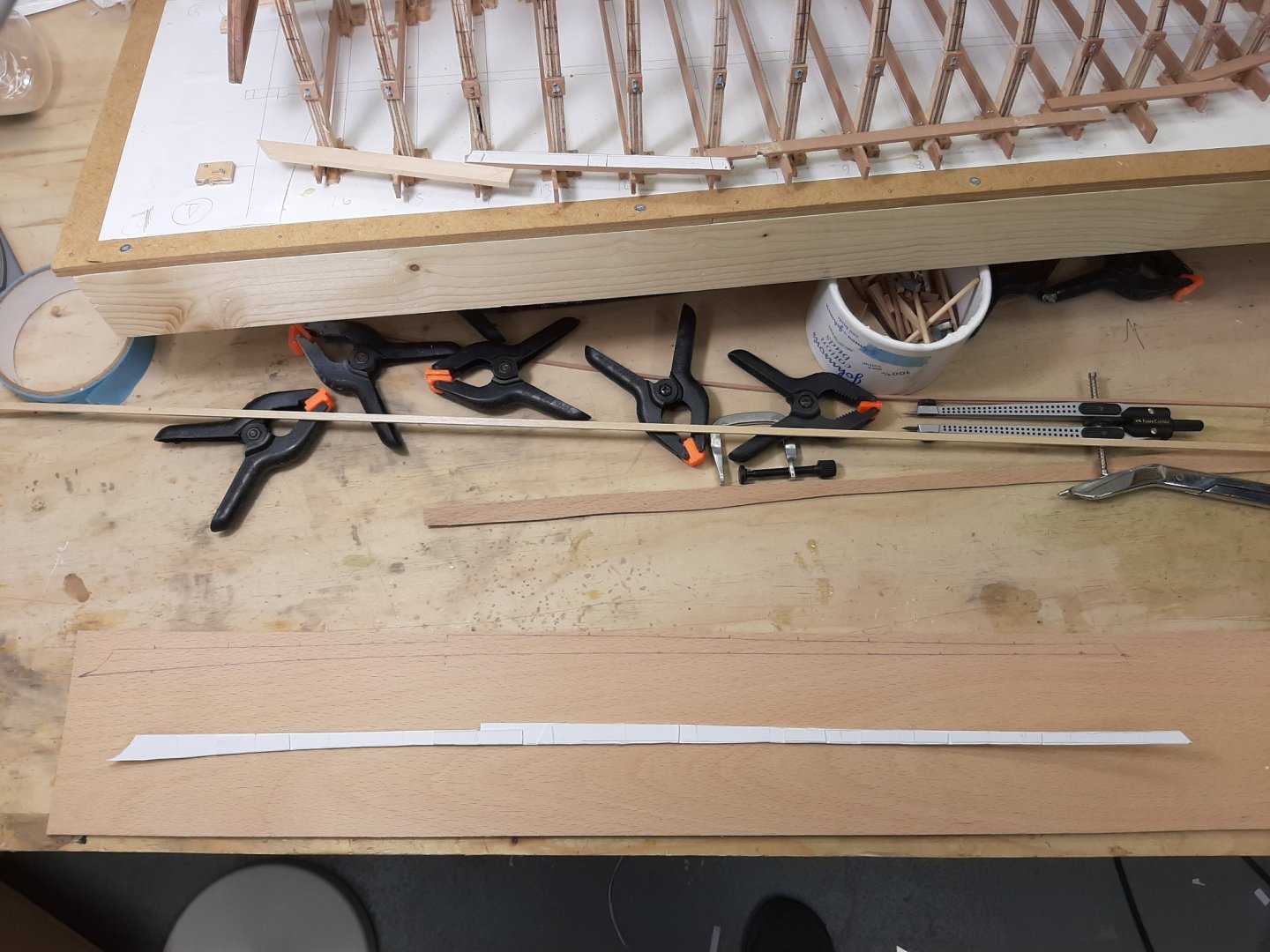
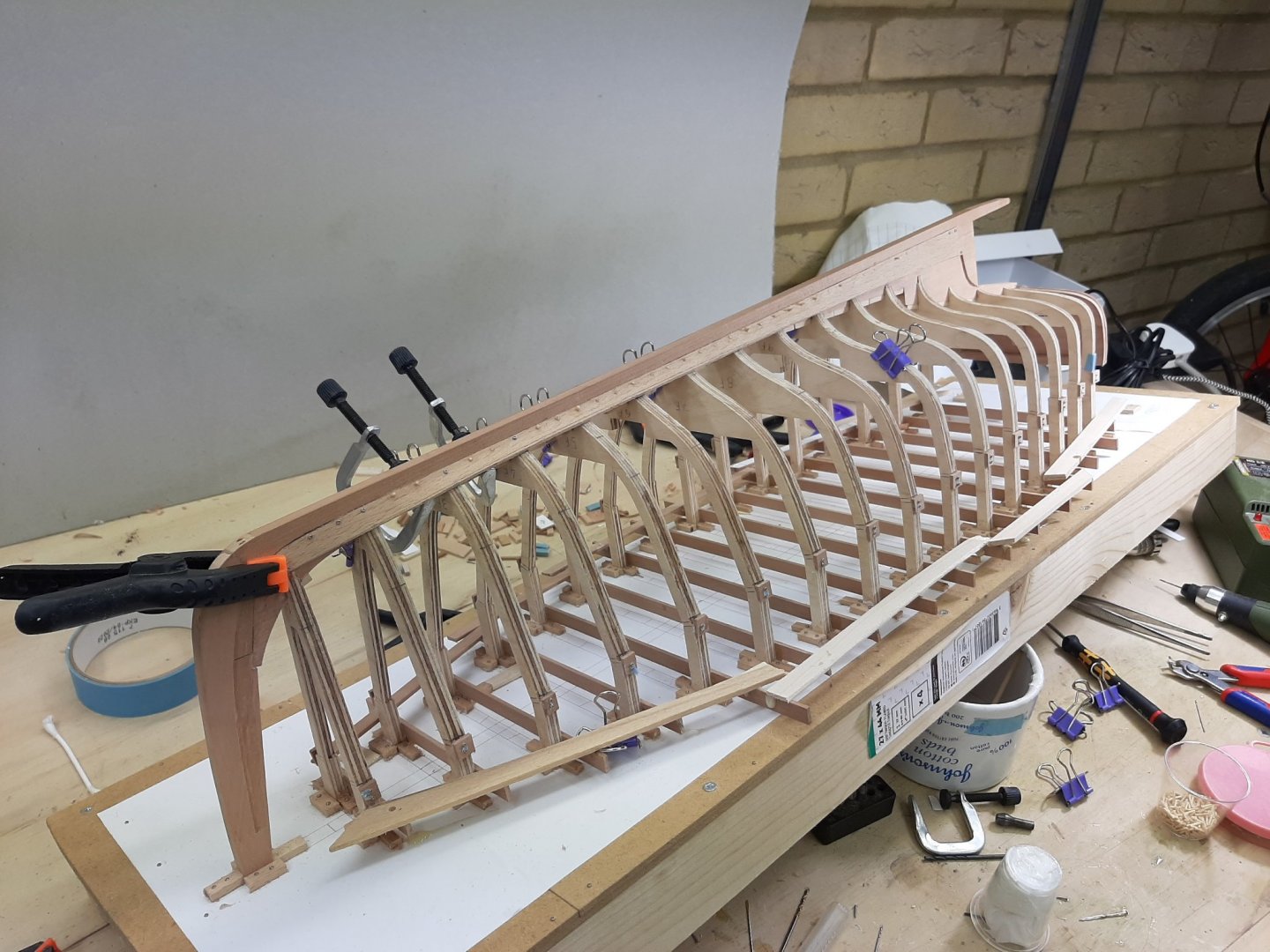
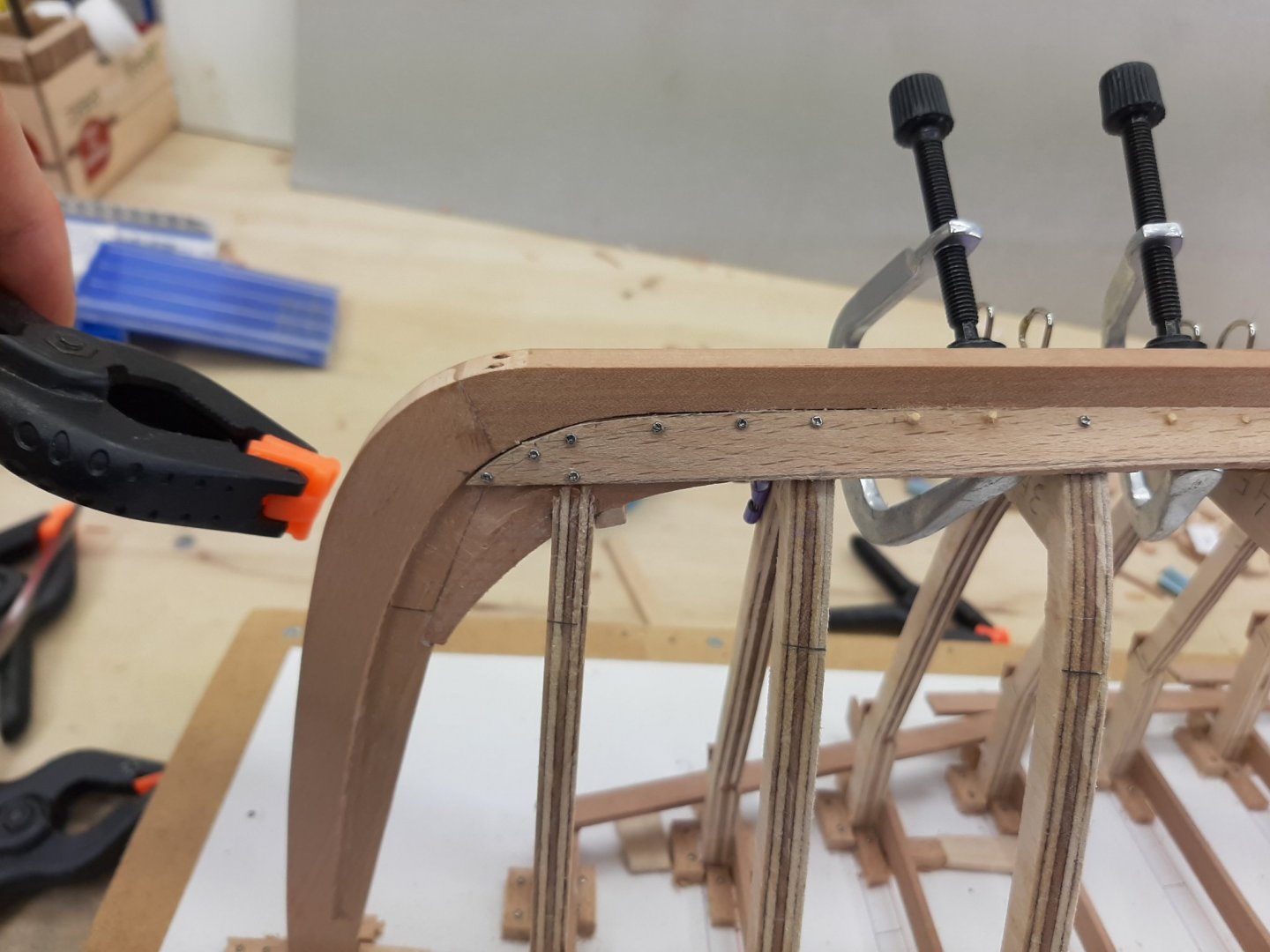
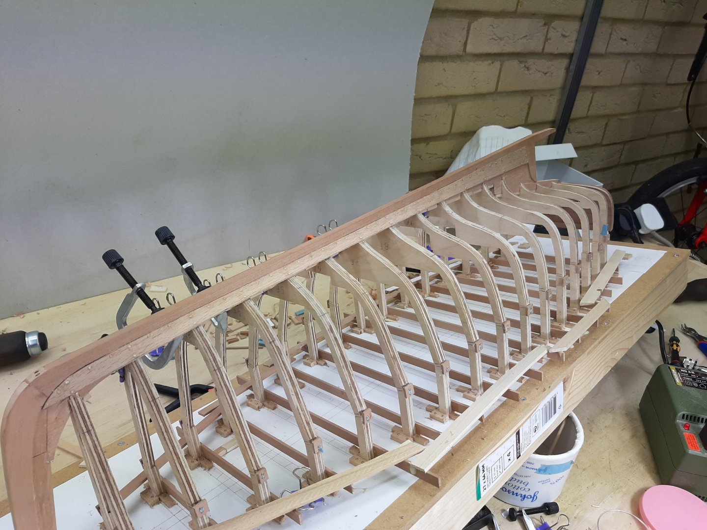
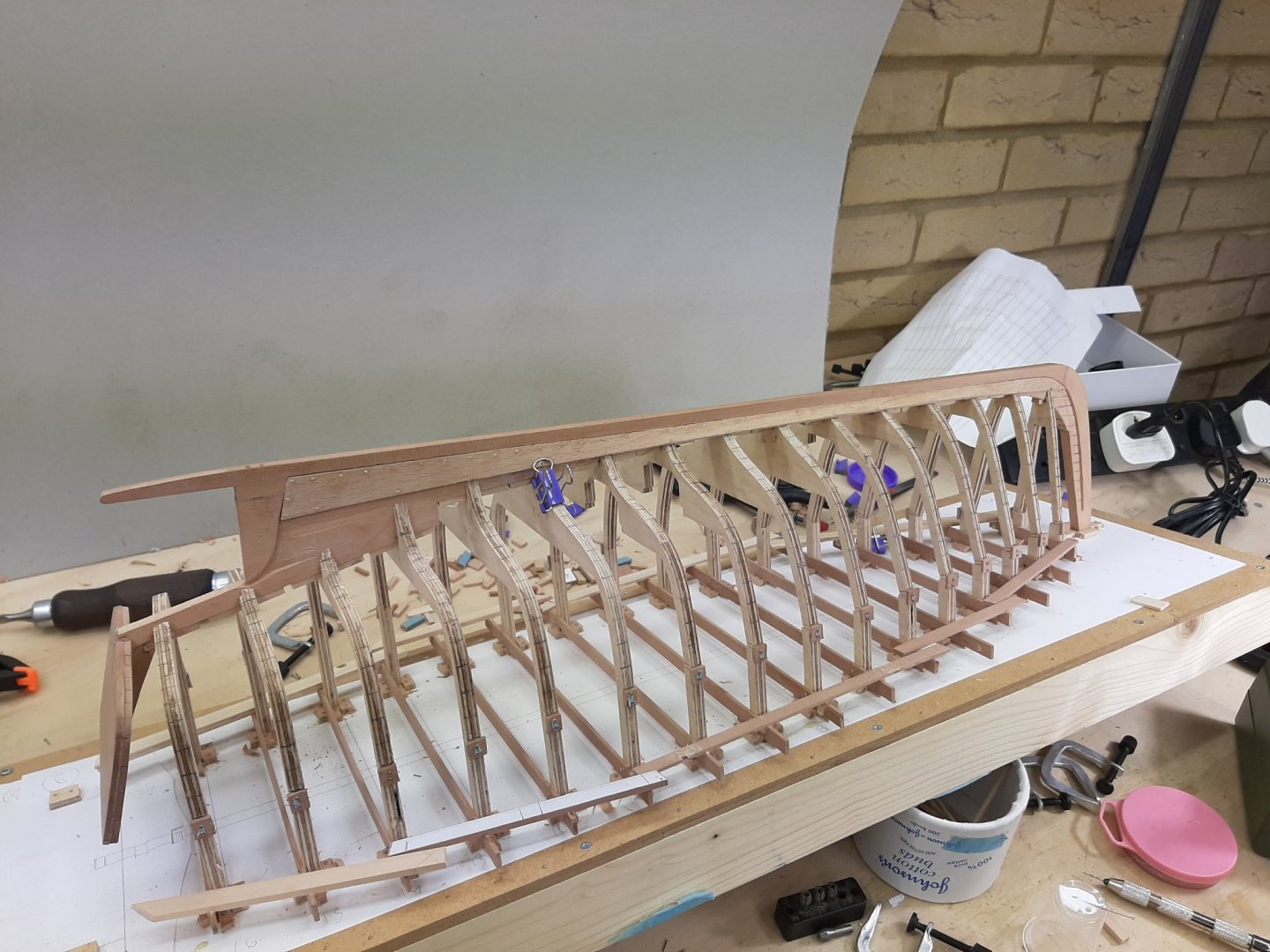
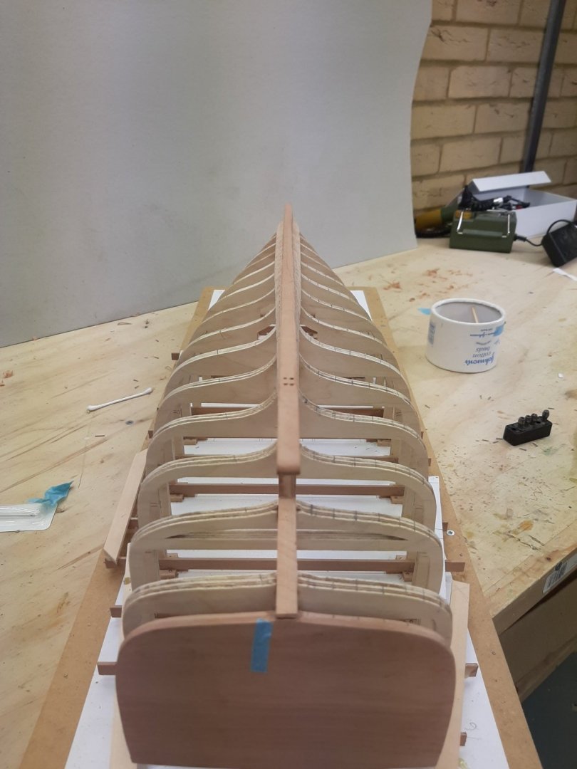
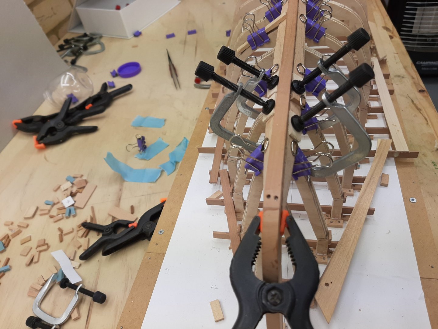
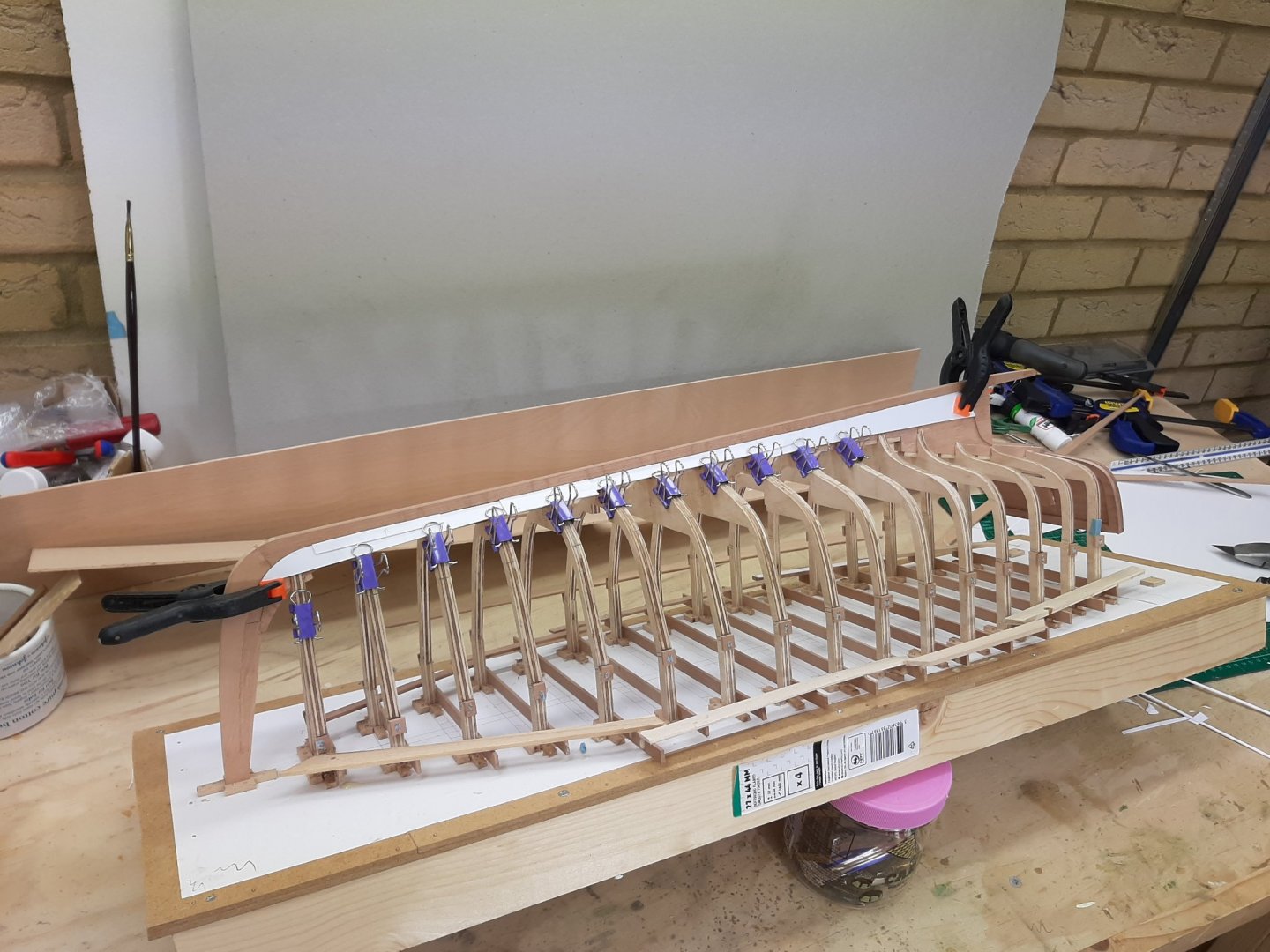
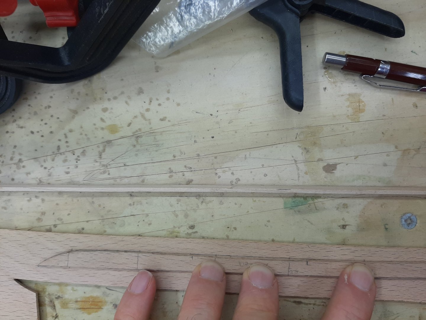
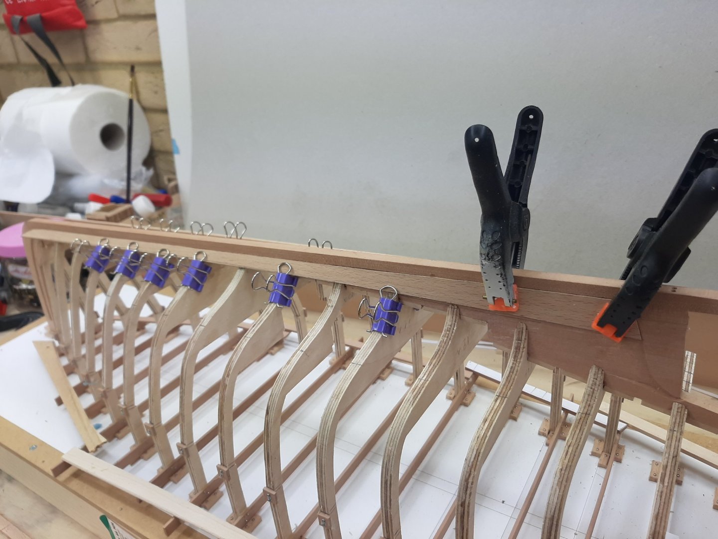
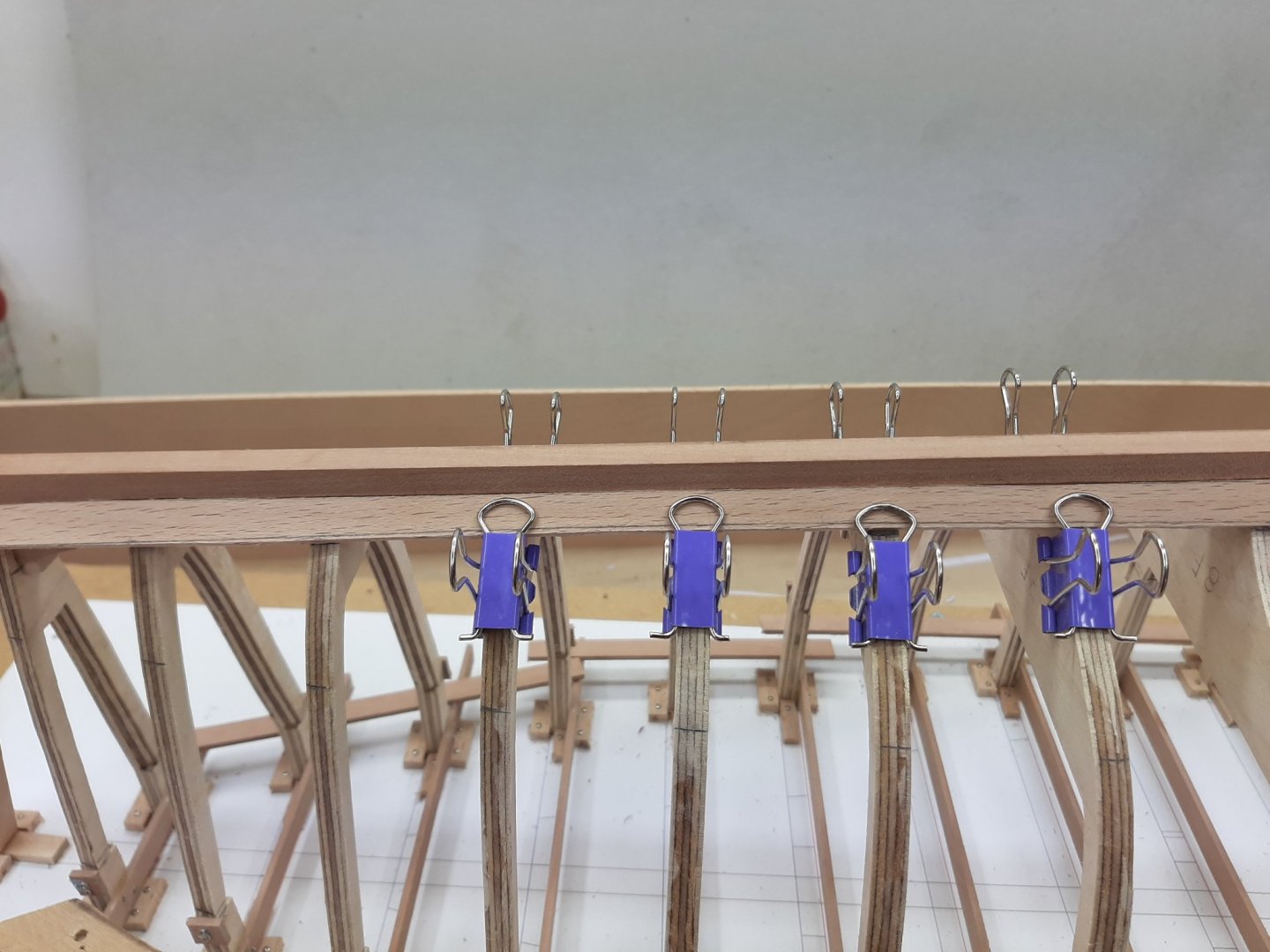
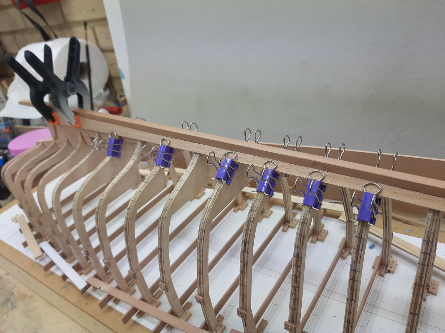
.thumb.jpg.6fd4c1b78768bb3efd745ab810936005.jpg) A bit more progress so another short post. All the planks so far have been difficult to make, mainly to the significant twist the wood had to take. This twist makes the plank to deviate so getting an accurate template is difficult-the slightest degree of edge bend will cause problems. The next plank I hope will be the last of the tricky ones. Indeed, it took many attempts to get card patterns that looked ok but there was no waisted wood-I got both sides with the first try. I think I am getting better at it! This is the paper pattern that defines only the shape of the one (bottom) edge. Many more followed to fine tune the shape The plank cut and dry fitted. I was concerned how it would fit with the previous vertical plank but actually this was not a problem. This plank again is very straight, so far the initial planning of the run of the planks seems to be ok. Now, this plank is 60 cm long, in the actual boat it would be a 6 m plank. I am sure though that stock 6 m long and 20 cm wide should be available. Otherwise the planks would have to be scarfed. Then I made the other side. The two planks are not identical! Then both planks were steamed and clamped in place. There are a couple of planks that seem a bit low and do not touch the planks well. The 2 mm planks are so stiff that easily show the problematic areas. Maybe they will need shiming-maybe not The fit at the stern looks pretty good. I really expected this area to cause massive problems, I guess Chapelle knew what he was doing! Now, I decided not to screw the planks immediately because I noticed that the gaps between the previous two planks have widened. I guess Noel and Wefalck were right to raise concerns. This will be sorted with some filler. This time, I got the bow heights right This photo however raises another issue. At some point, I will need to taper the stem. From the keel up, it will progressively start to get more narrow , following the angle of the planking. I should have probably done it earlier, at least to take the bulk of he wood off. I am not sure whether to do it now or later. To remove so much wood, sharp chisels but also rough handling will be needed. Maybe do it after planking, when the boat will be very stiff but then I will need to be vey careful not to mark the planks. Maybe a middle way would be to keep using screws so that any damaged plank could be replaced. I d really be interested to hear your thoughts on this! Vaddoc
A bit more progress so another short post. All the planks so far have been difficult to make, mainly to the significant twist the wood had to take. This twist makes the plank to deviate so getting an accurate template is difficult-the slightest degree of edge bend will cause problems. The next plank I hope will be the last of the tricky ones. Indeed, it took many attempts to get card patterns that looked ok but there was no waisted wood-I got both sides with the first try. I think I am getting better at it! This is the paper pattern that defines only the shape of the one (bottom) edge. Many more followed to fine tune the shape The plank cut and dry fitted. I was concerned how it would fit with the previous vertical plank but actually this was not a problem. This plank again is very straight, so far the initial planning of the run of the planks seems to be ok. Now, this plank is 60 cm long, in the actual boat it would be a 6 m plank. I am sure though that stock 6 m long and 20 cm wide should be available. Otherwise the planks would have to be scarfed. Then I made the other side. The two planks are not identical! Then both planks were steamed and clamped in place. There are a couple of planks that seem a bit low and do not touch the planks well. The 2 mm planks are so stiff that easily show the problematic areas. Maybe they will need shiming-maybe not The fit at the stern looks pretty good. I really expected this area to cause massive problems, I guess Chapelle knew what he was doing! Now, I decided not to screw the planks immediately because I noticed that the gaps between the previous two planks have widened. I guess Noel and Wefalck were right to raise concerns. This will be sorted with some filler. This time, I got the bow heights right This photo however raises another issue. At some point, I will need to taper the stem. From the keel up, it will progressively start to get more narrow , following the angle of the planking. I should have probably done it earlier, at least to take the bulk of he wood off. I am not sure whether to do it now or later. To remove so much wood, sharp chisels but also rough handling will be needed. Maybe do it after planking, when the boat will be very stiff but then I will need to be vey careful not to mark the planks. Maybe a middle way would be to keep using screws so that any damaged plank could be replaced. I d really be interested to hear your thoughts on this! Vaddoc


-
Thanks Keith! It might seem complex but in reality Carvel planking just needs patience and batens. Clinker will need a bit extra head scratching but more later on, when the planking of the Yawl starts. Not to worry Wefalck, it is great that you all are on board on this journey!
-
This is wonderful model GL, congratulations! I think the worse is behind us, we ll find a balance soon. An Ancre monograph, this sounds very exciting. After you ve tied the loose end of course...
-
Indeed Wefalck, this is what I intended to do, leave the planks wider to allow me to do fine adjustments and create bevels, so that the planks would touch edge to edge despite the angle. In practice, this is very difficult to do even at 1:10 scale-at least for me. However, what I do do is sand the high spots on the edge that meets the previous plank so that they meet better, but also sand the other edge to create a fair curve with as few high and low spots as possible-this makes fitting the next plank easier. I forgot to do this on the garboard though.
-
Hi Noel I do not think so. Indeed, there can be a large difference in width (negligible on length) between wet and dry wood, I ve seen 20% quoted for some woods and the Wood database site mentions that beech has high movement in service. However, one thing that impressed me is that the wood comes out of the steamer hot and pliable but very quickly cools down and actually feels very dry to touch-this takes seconds. Very different to soaking beech in water, the wood still becomes pretty pliable but is soaking wet-dries quickly but takes a few minutes. In any case, the wood is cut to template when dry and is tested on the boat when it dries after steaming-its me template that is wrong. The fitting issues are caused by the card paper that slightly edge bends, even 1 degree will create huge gaps in a 60 cm plank. Also the width of the paper template is important-too wide and the paper will sit at a different angle on the frame, causing the plank to deviate. Ideally, I would like to use 0.8 mm plywood but it will be too expensive. Thanks for visiting! Vaddoc
-
Dying/coloring rope; sources for purchase of quality rope
vaddoc replied to Tomculb's topic in Masting, rigging and sails
I d second making your own rope. Great fun, great rope. -
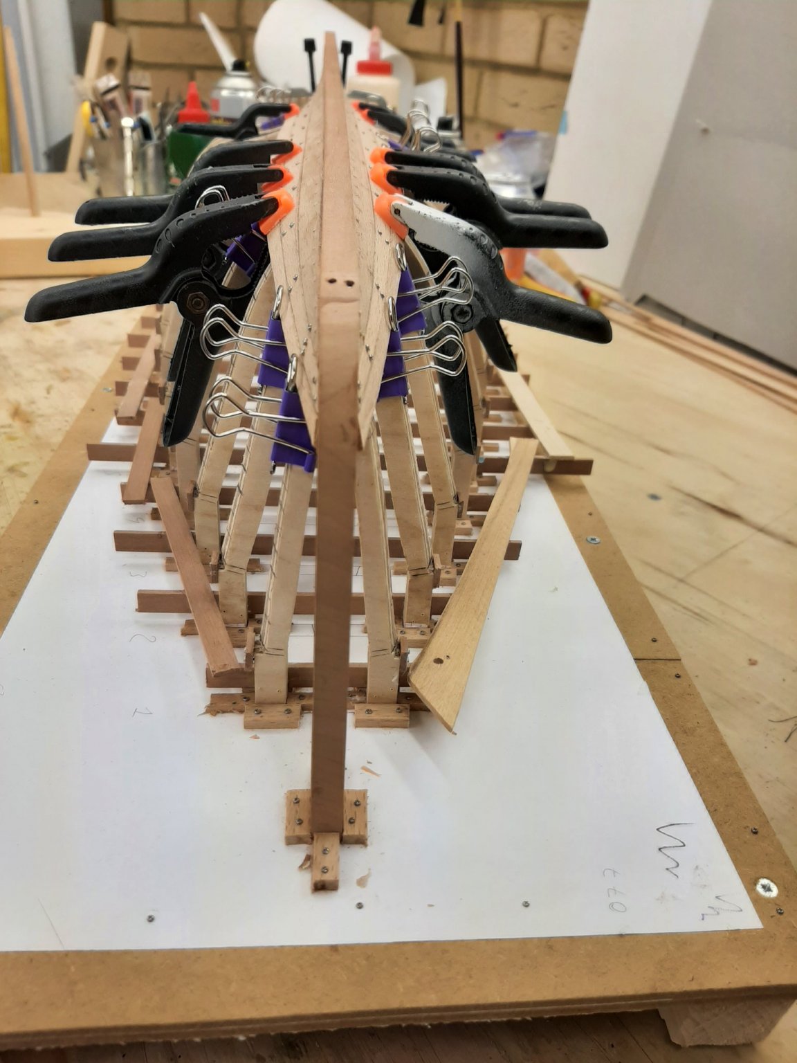
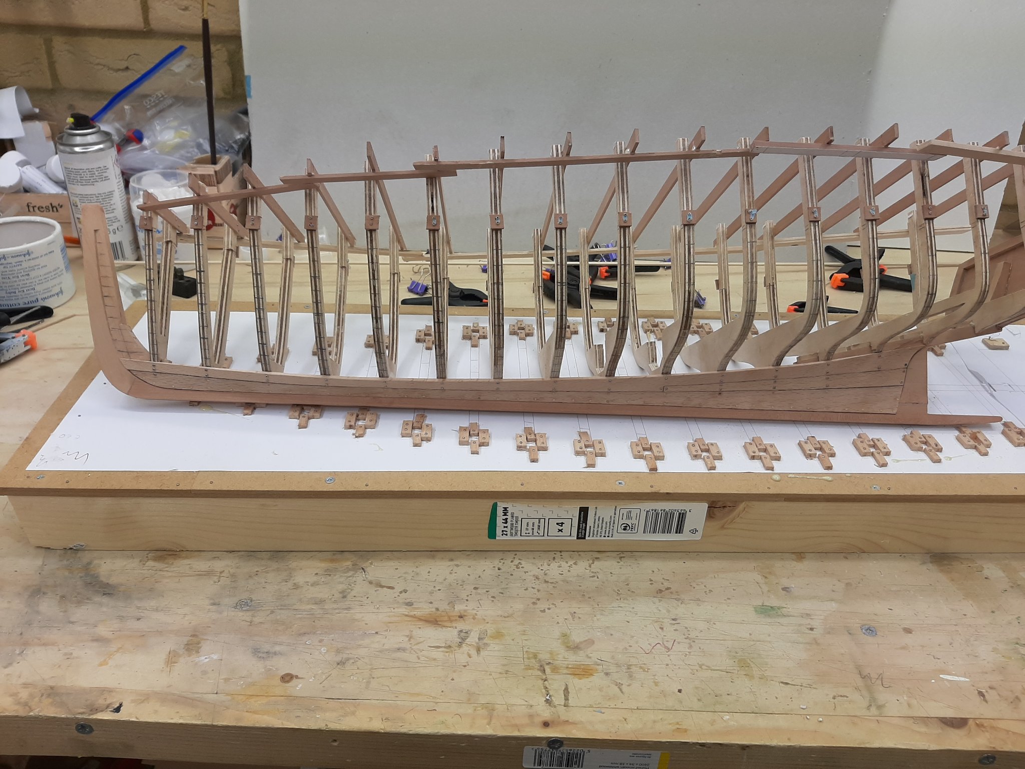
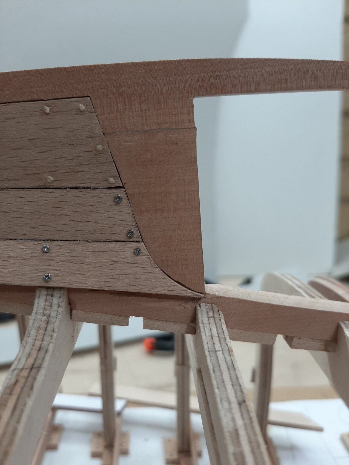
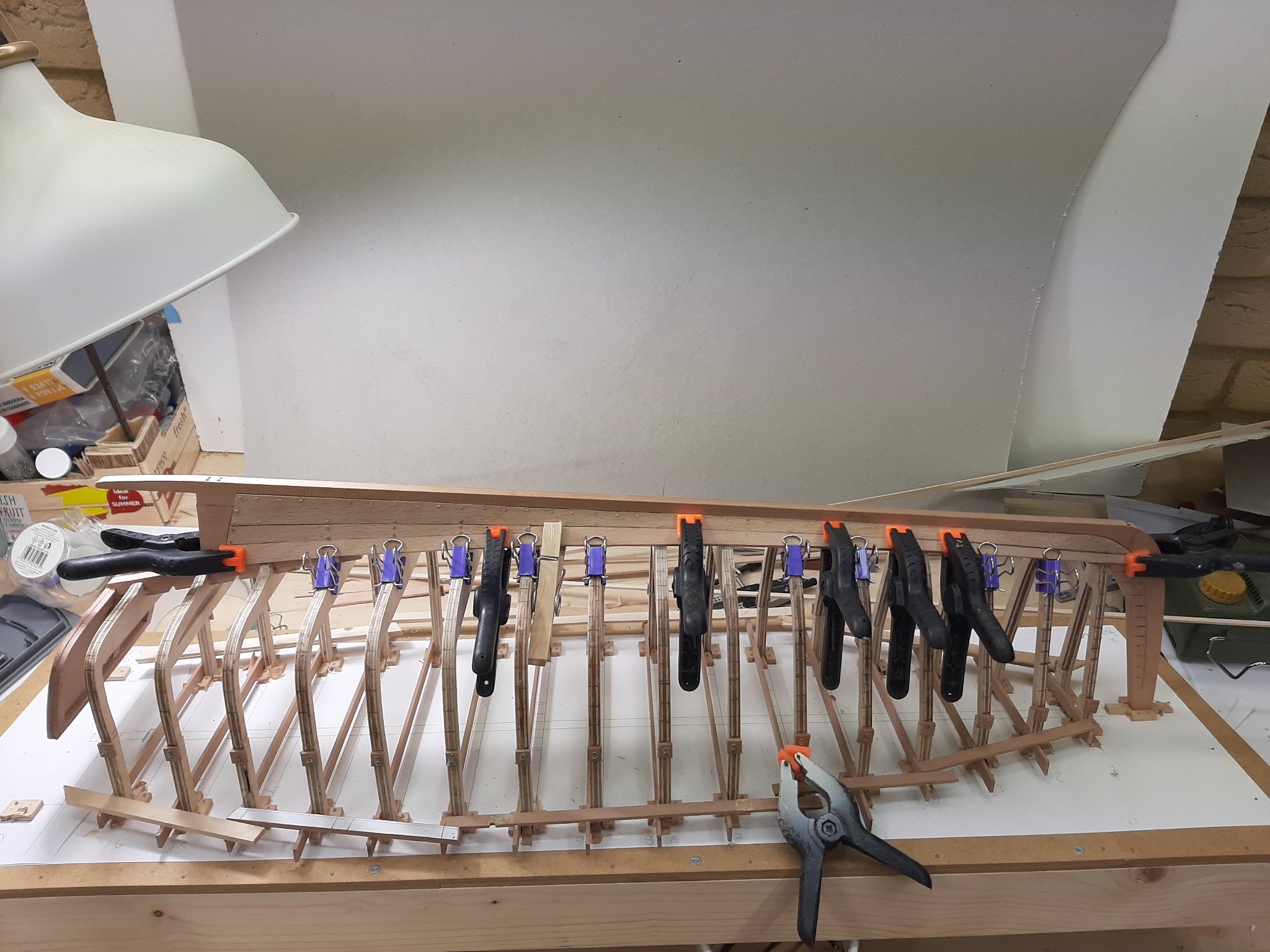
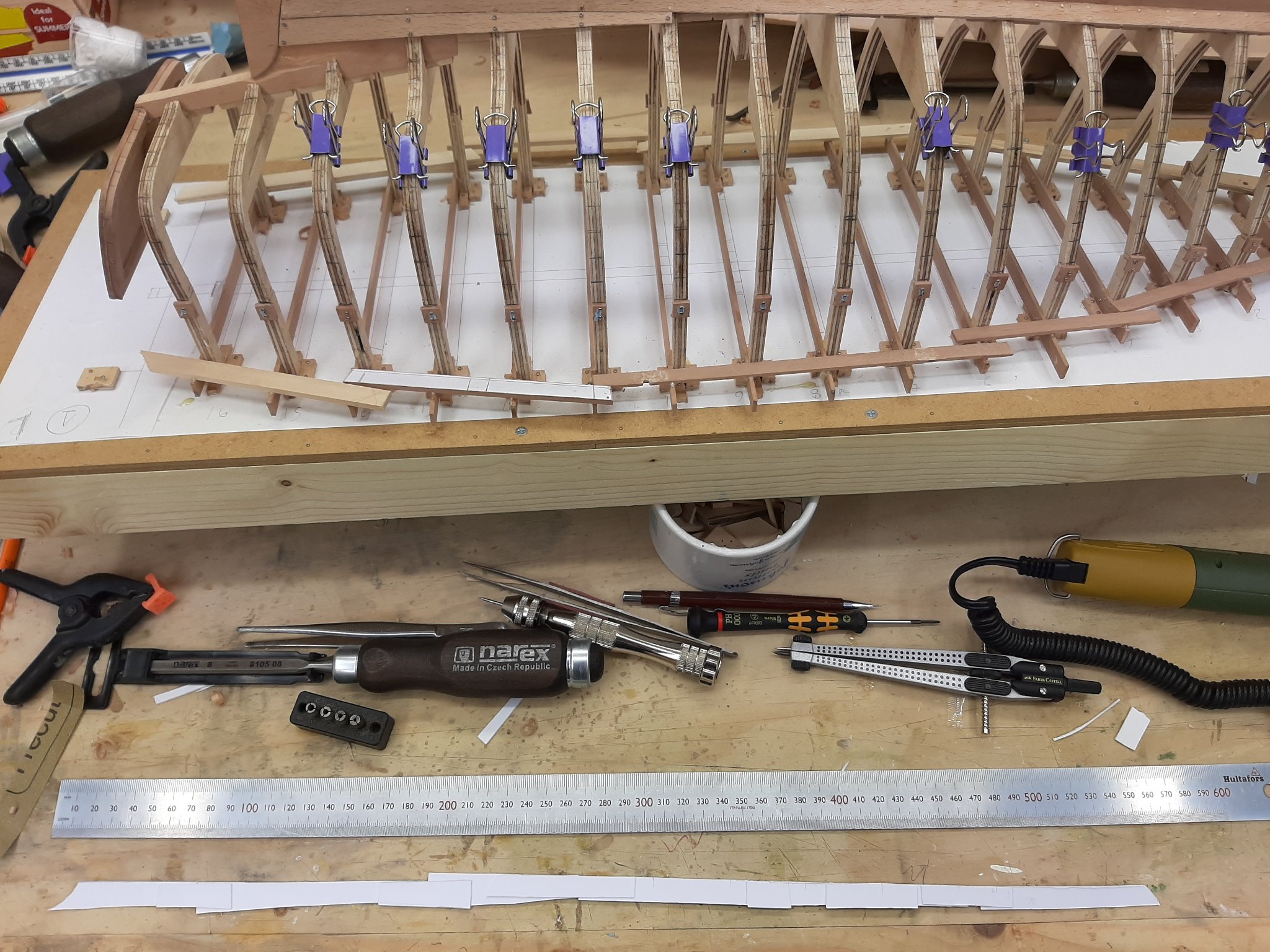
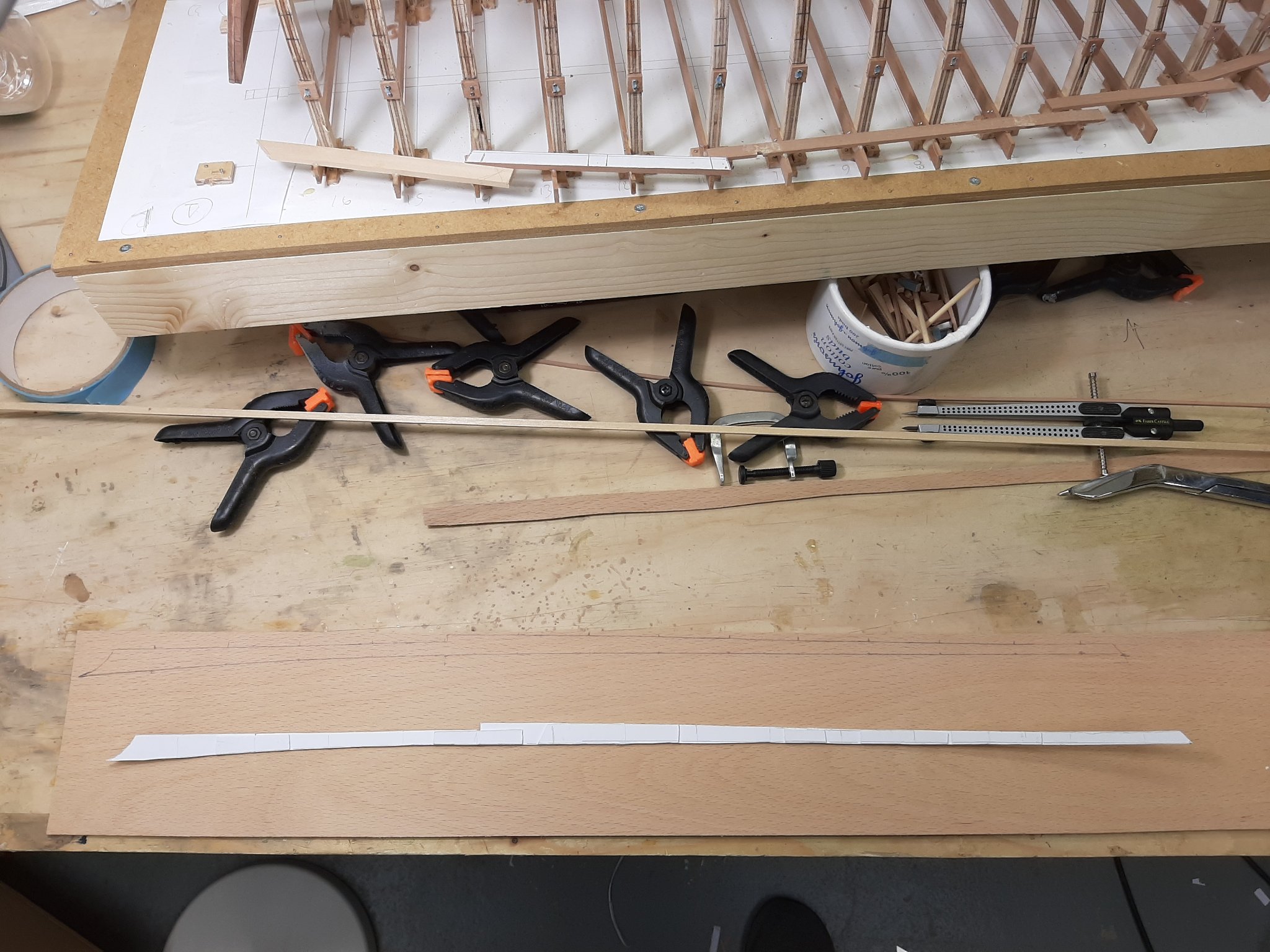
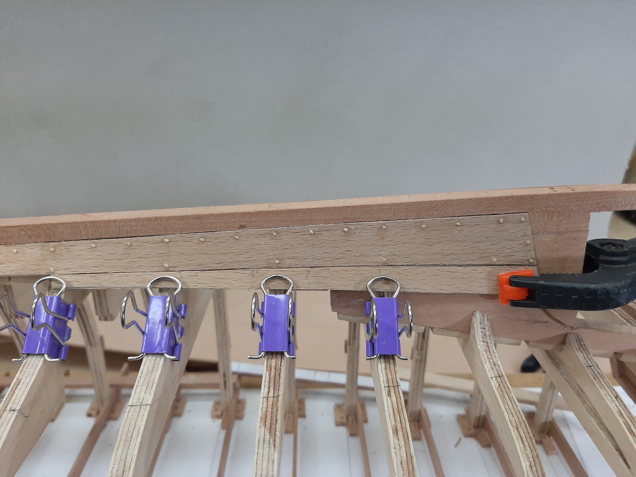
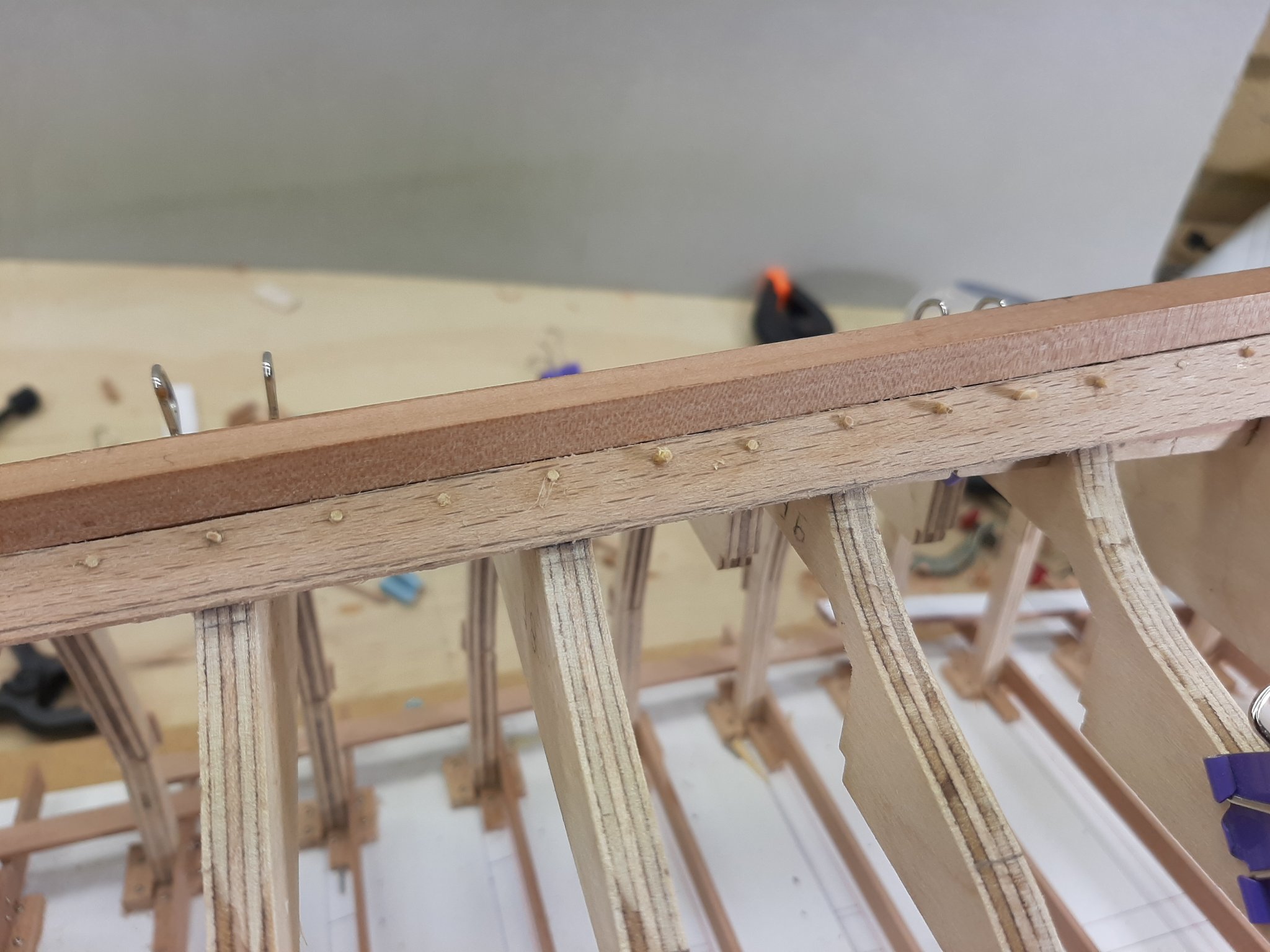
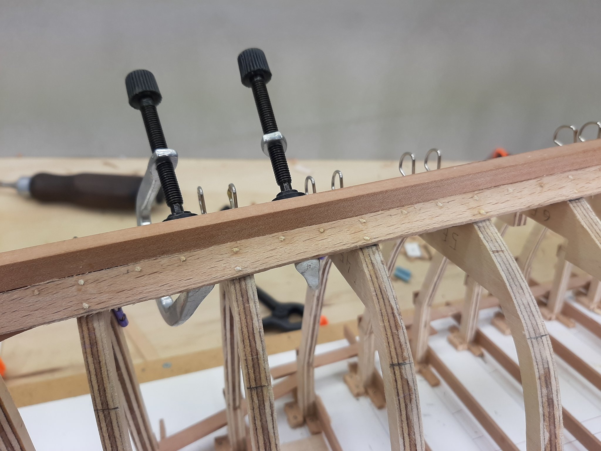
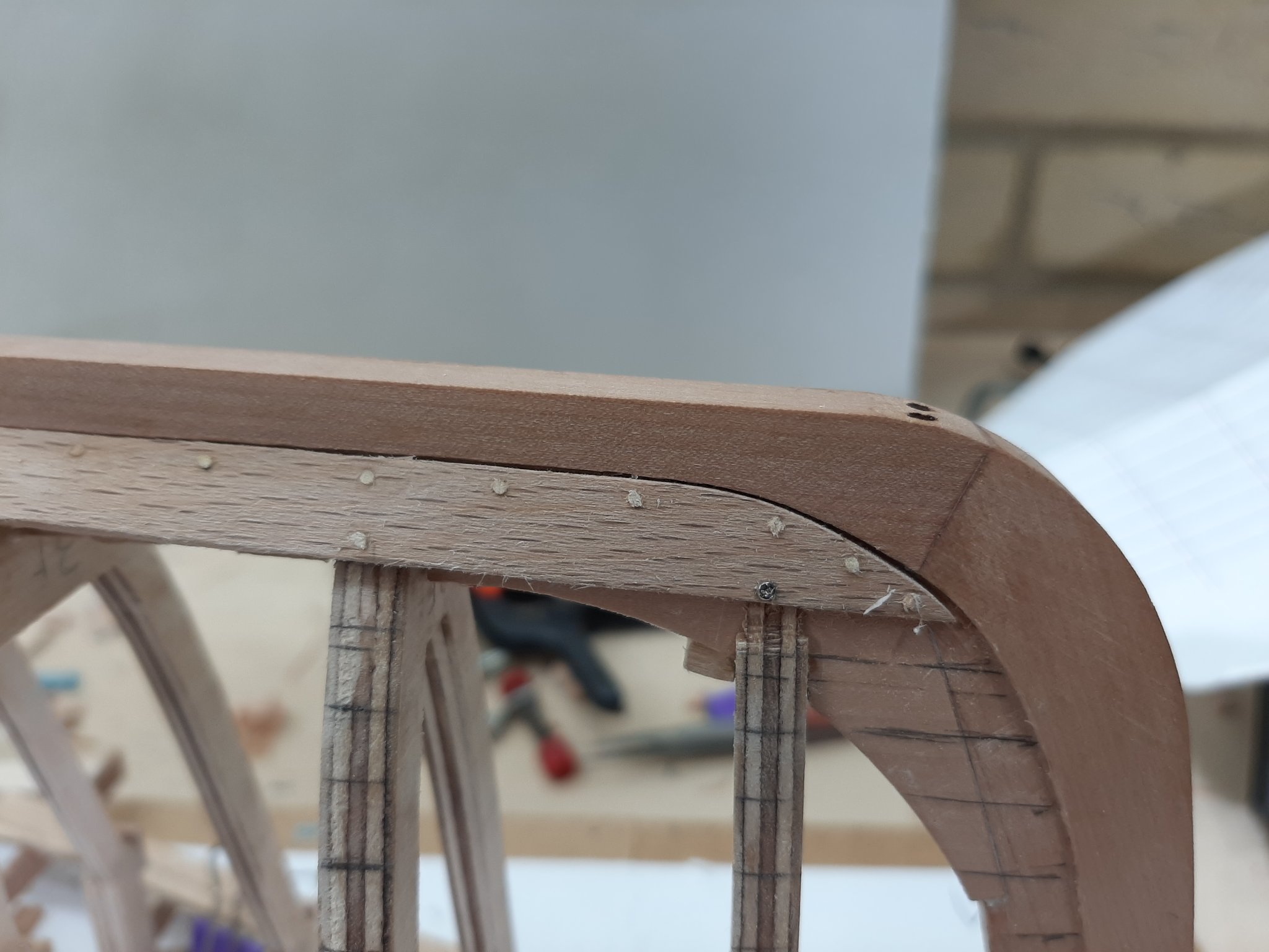
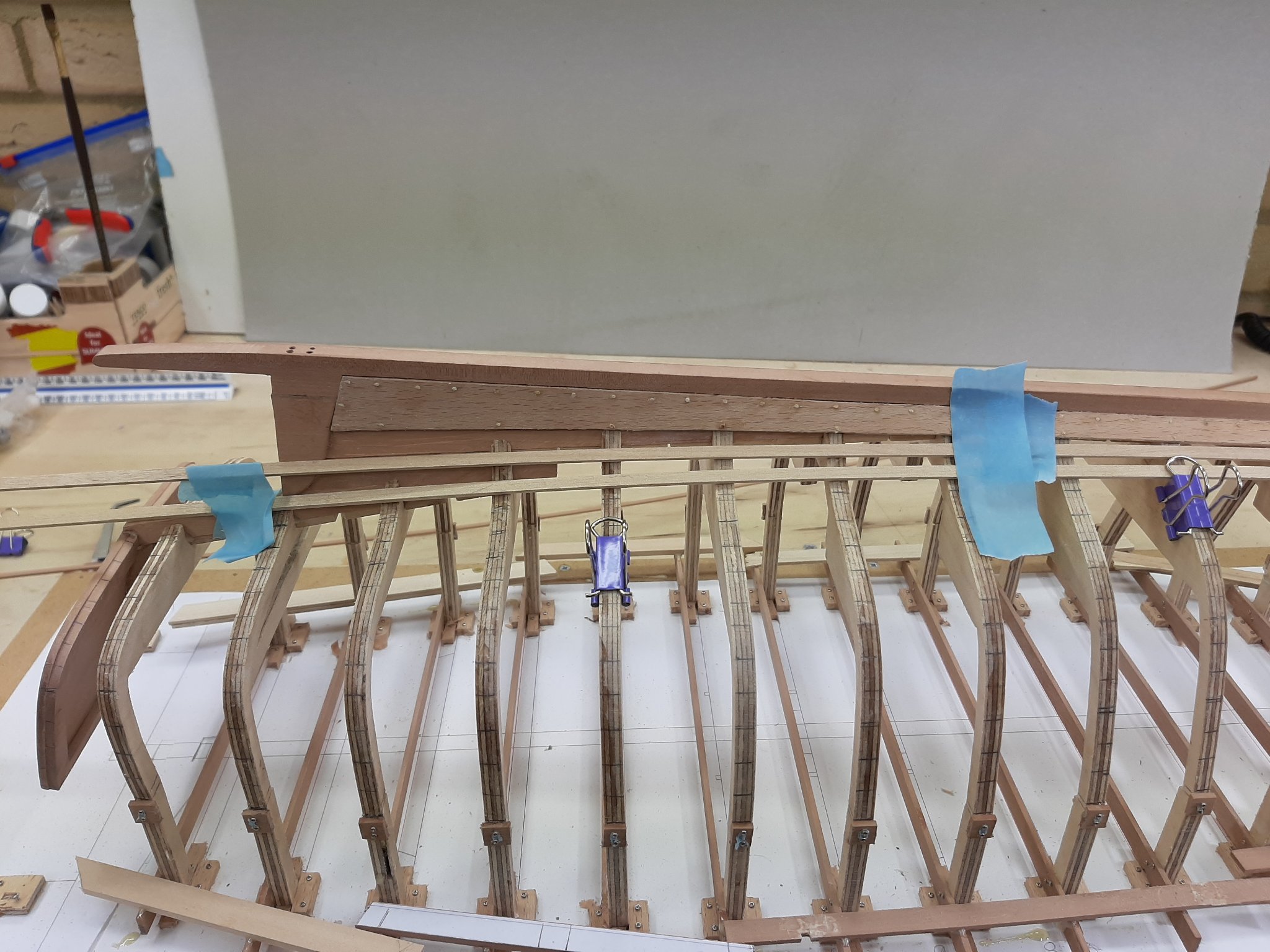
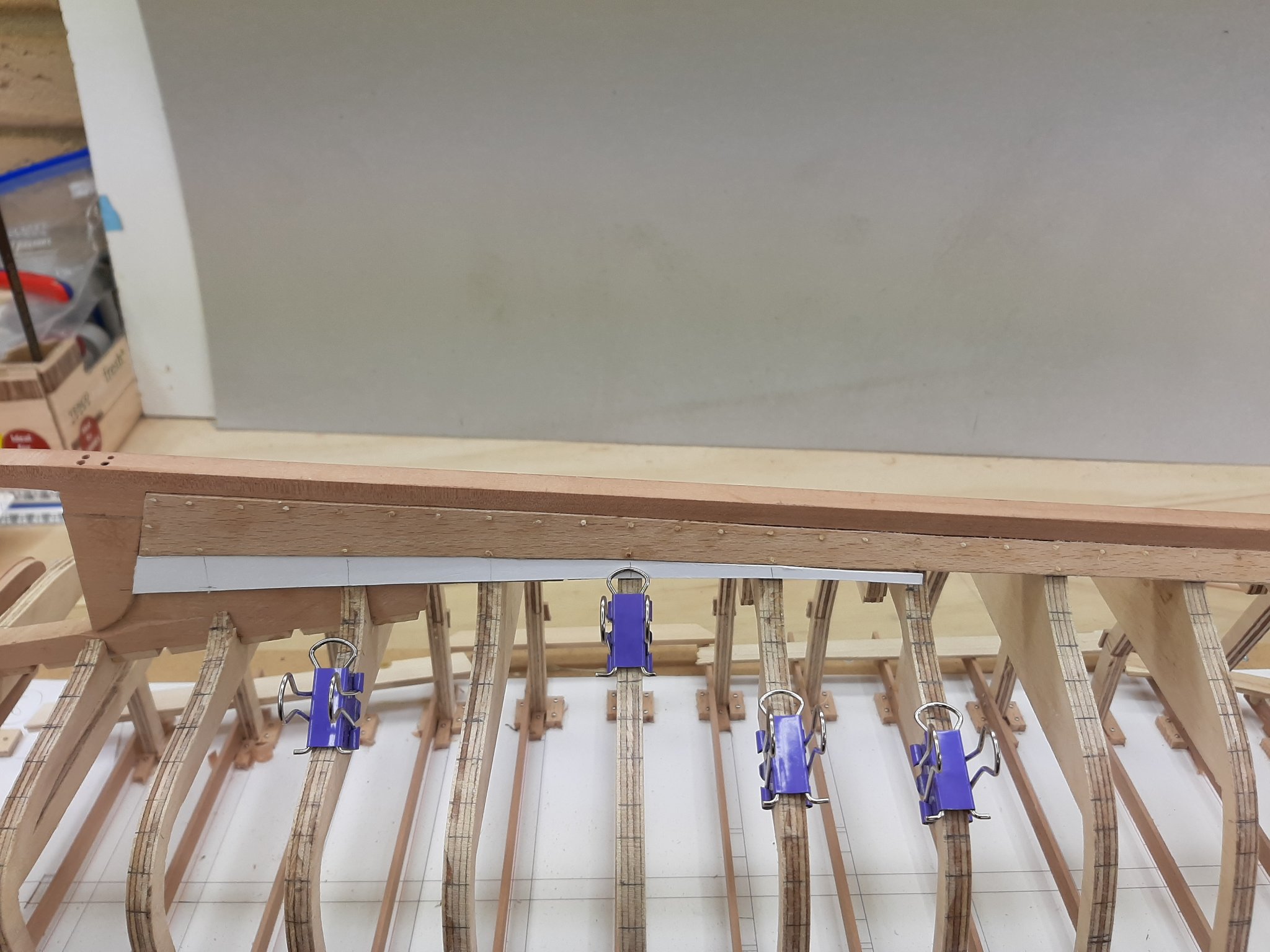
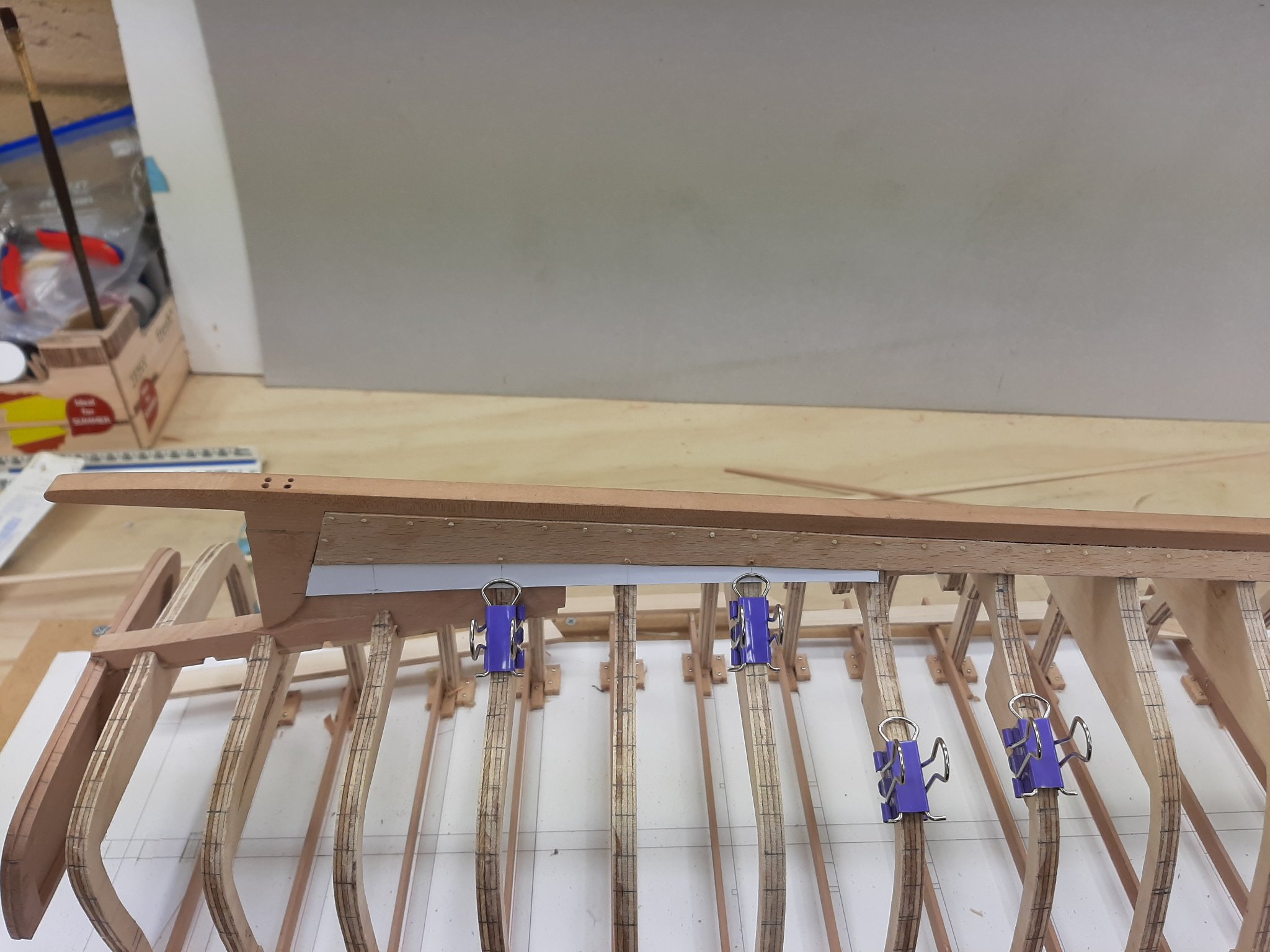
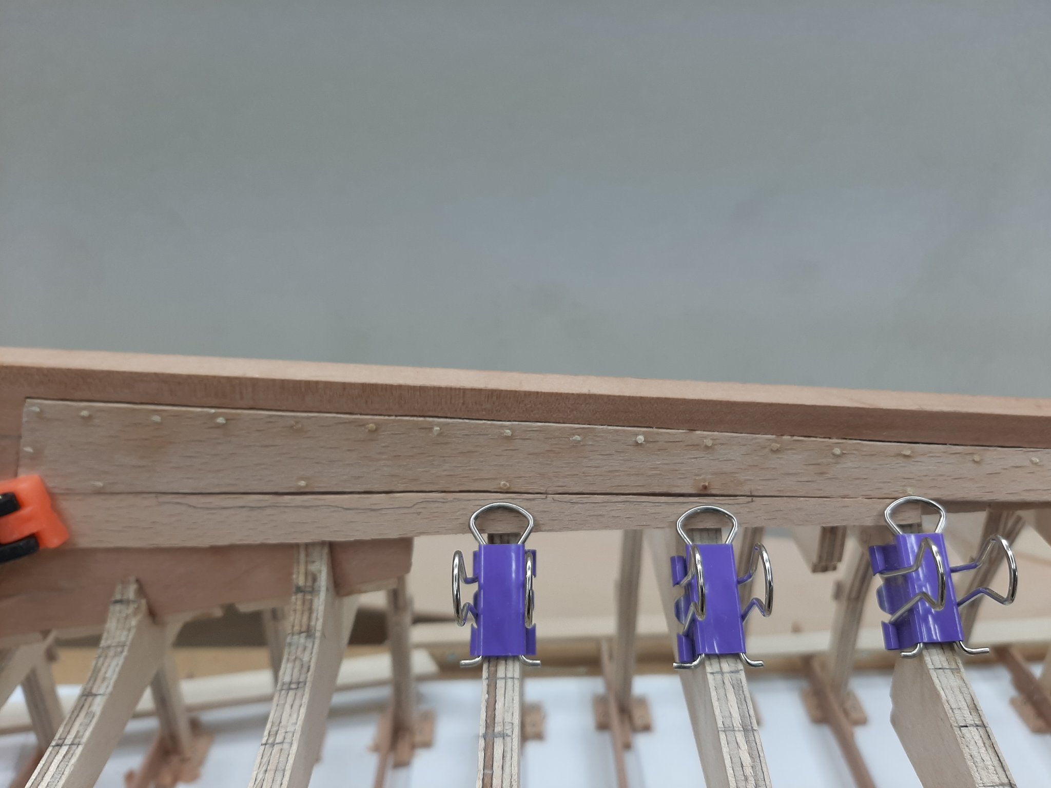
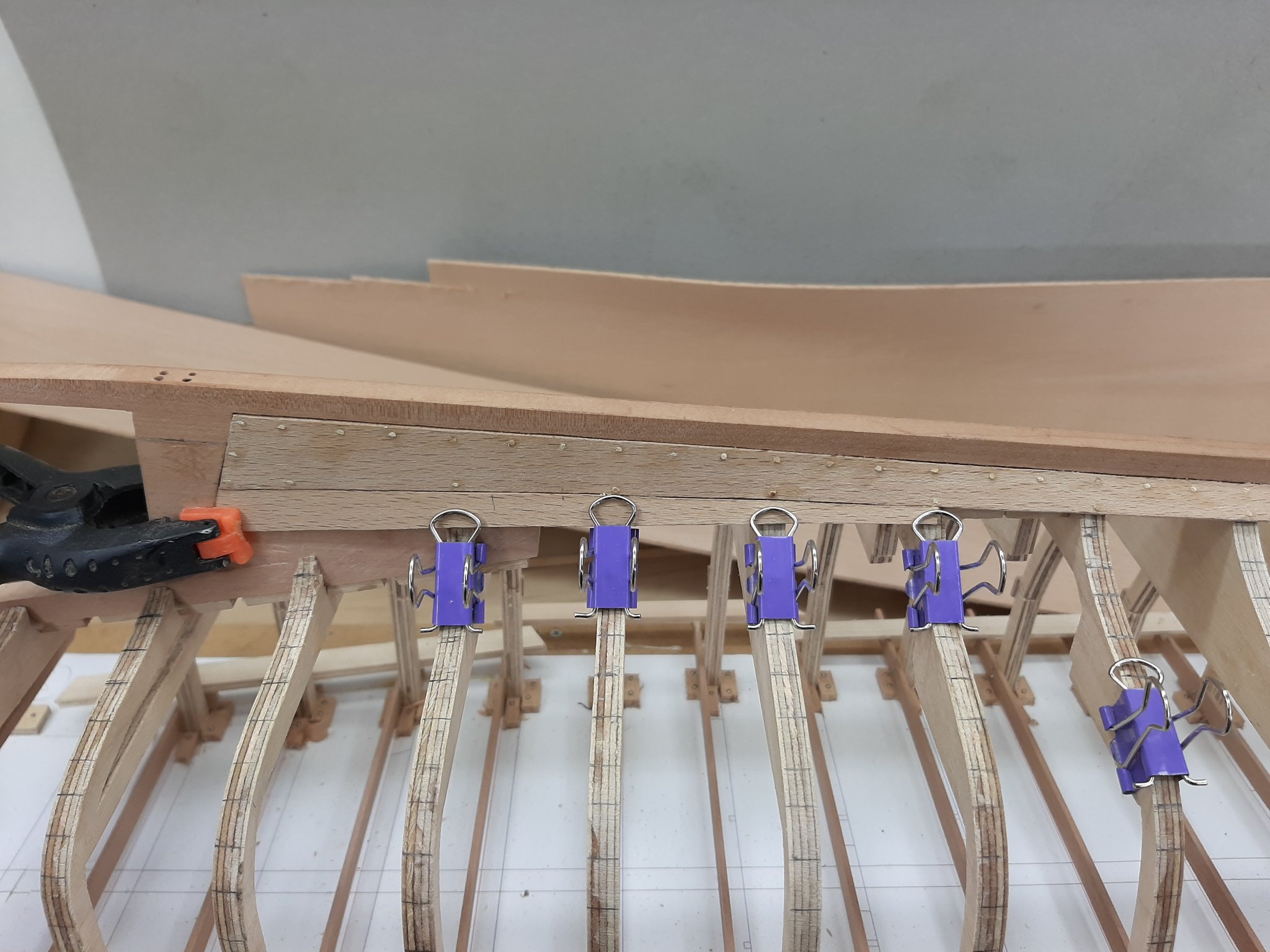
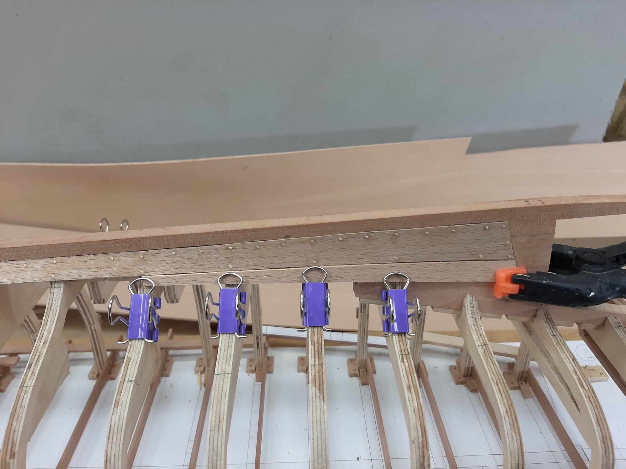
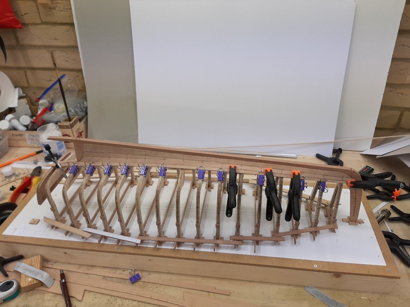
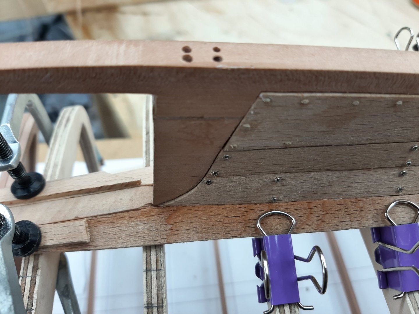
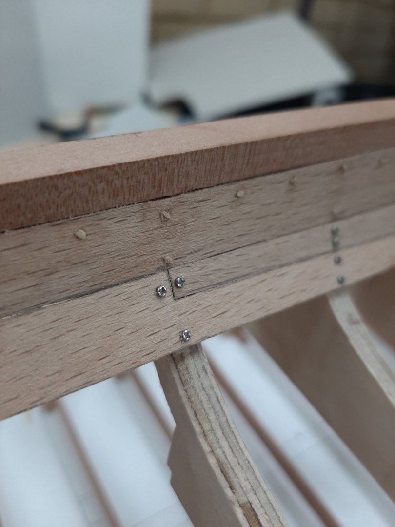
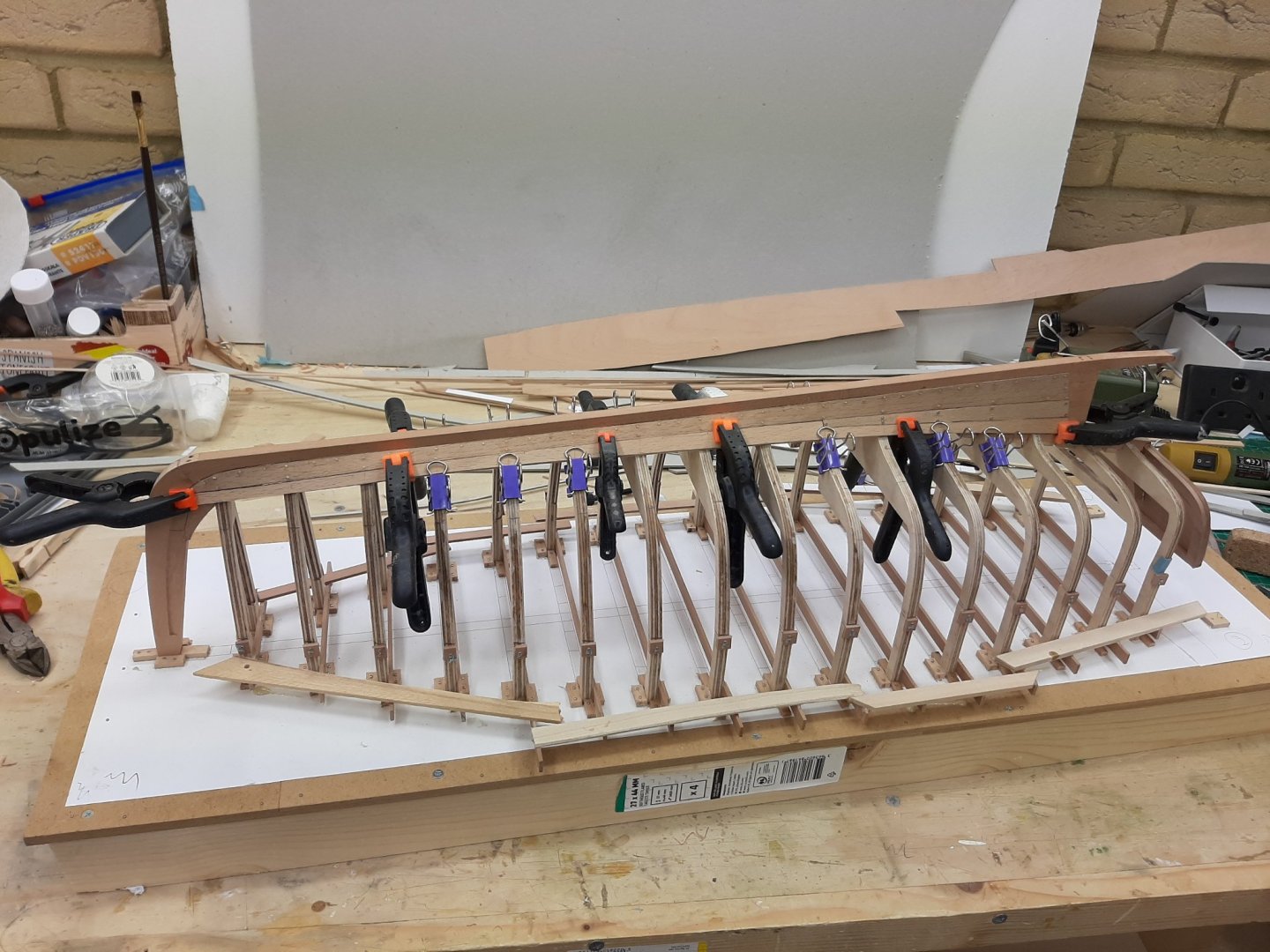
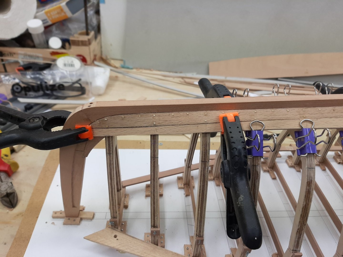
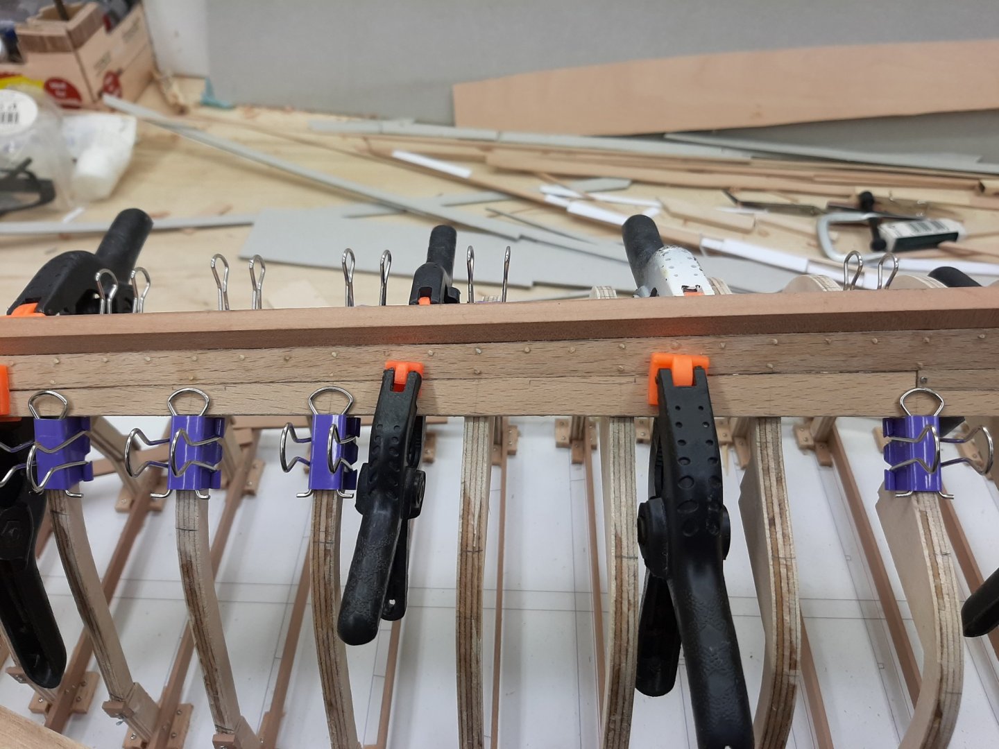
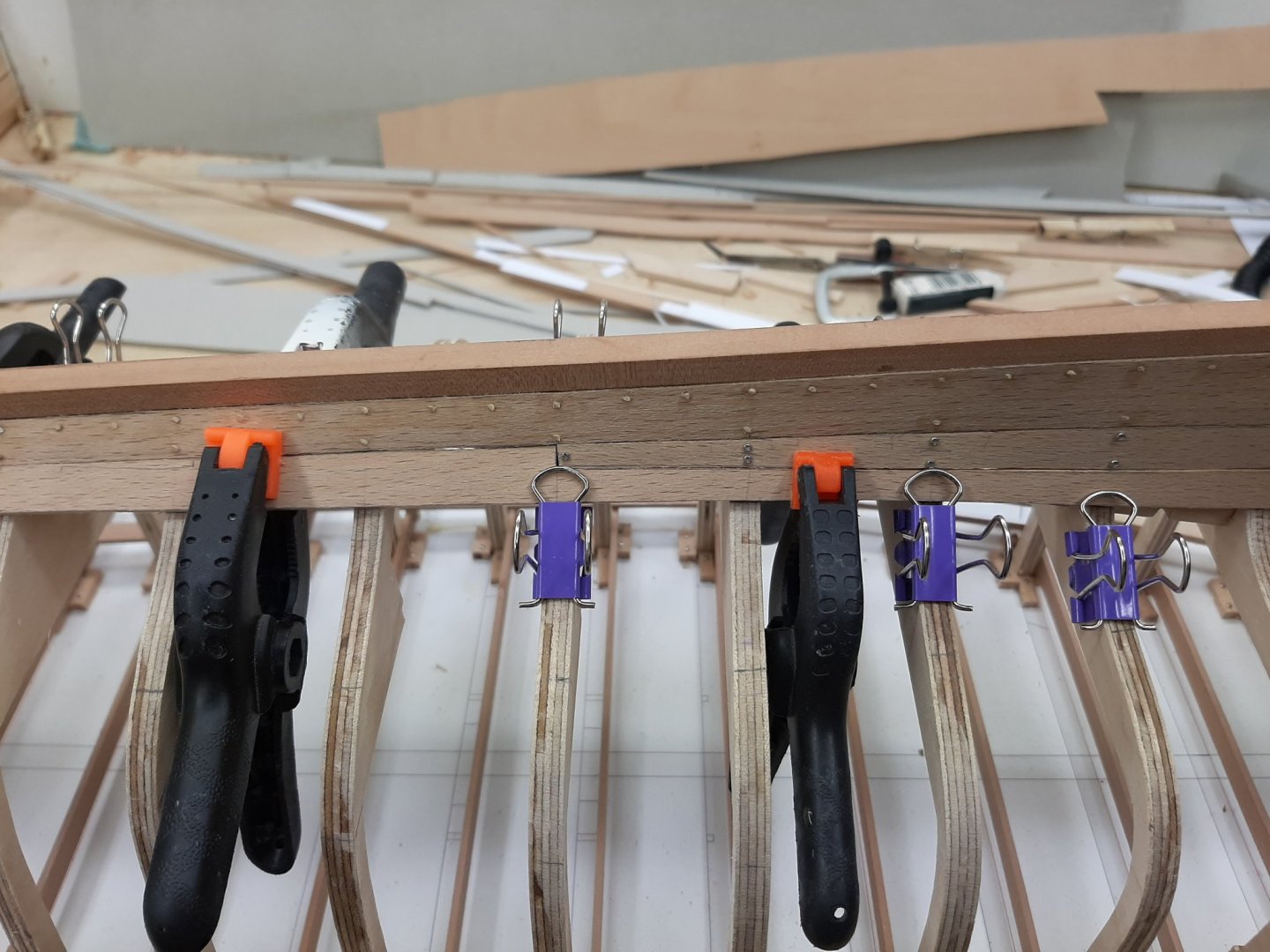
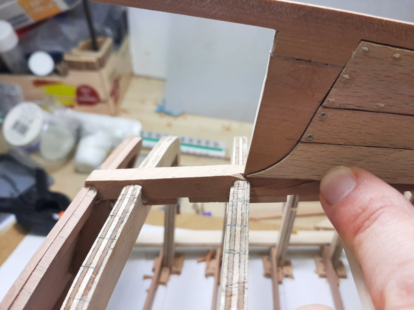
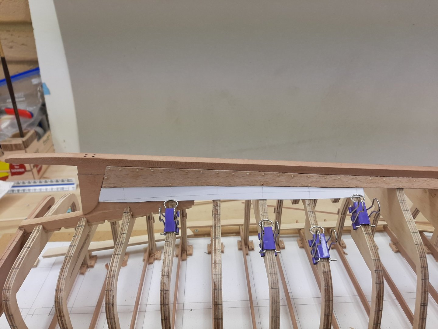
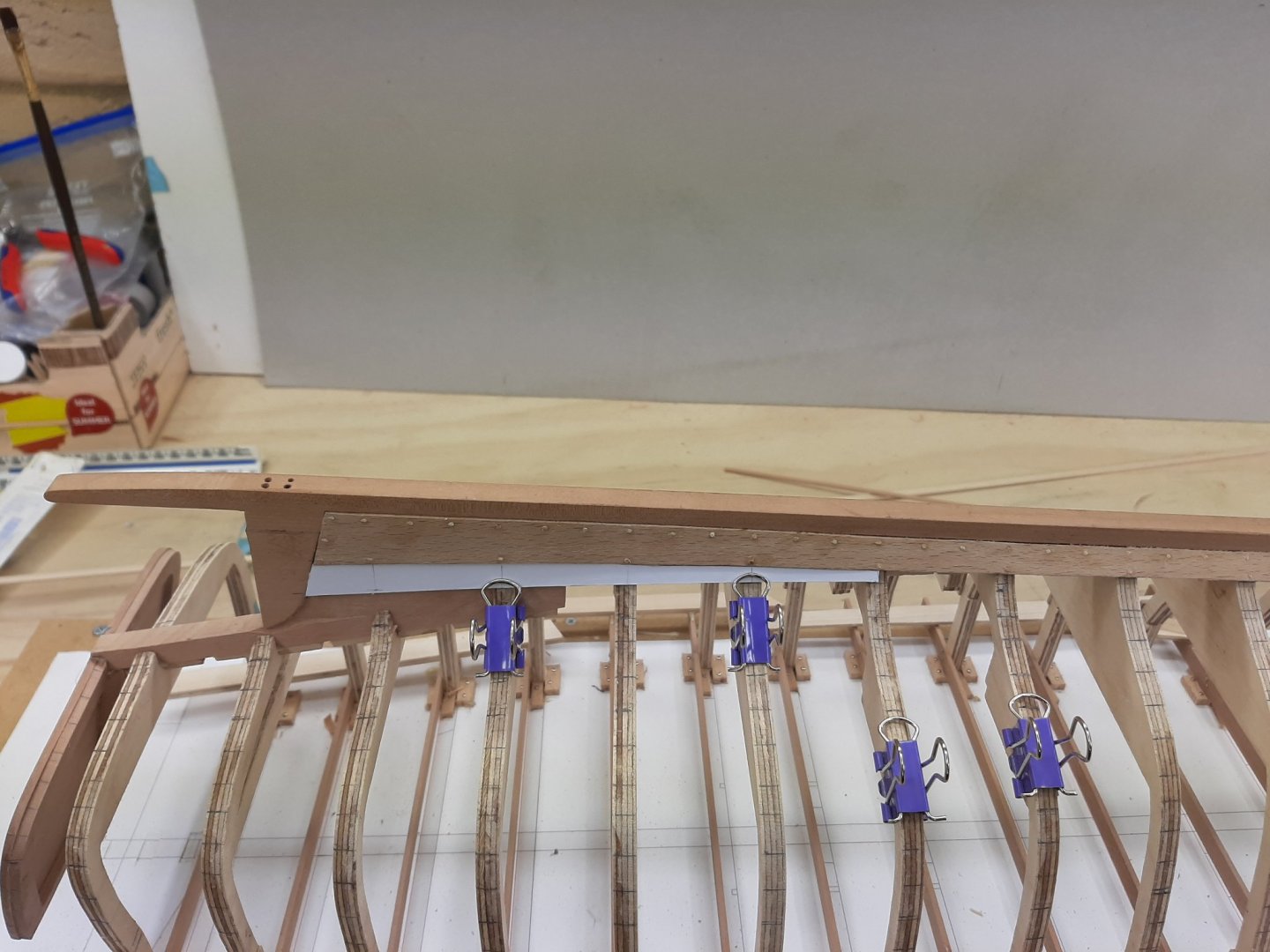
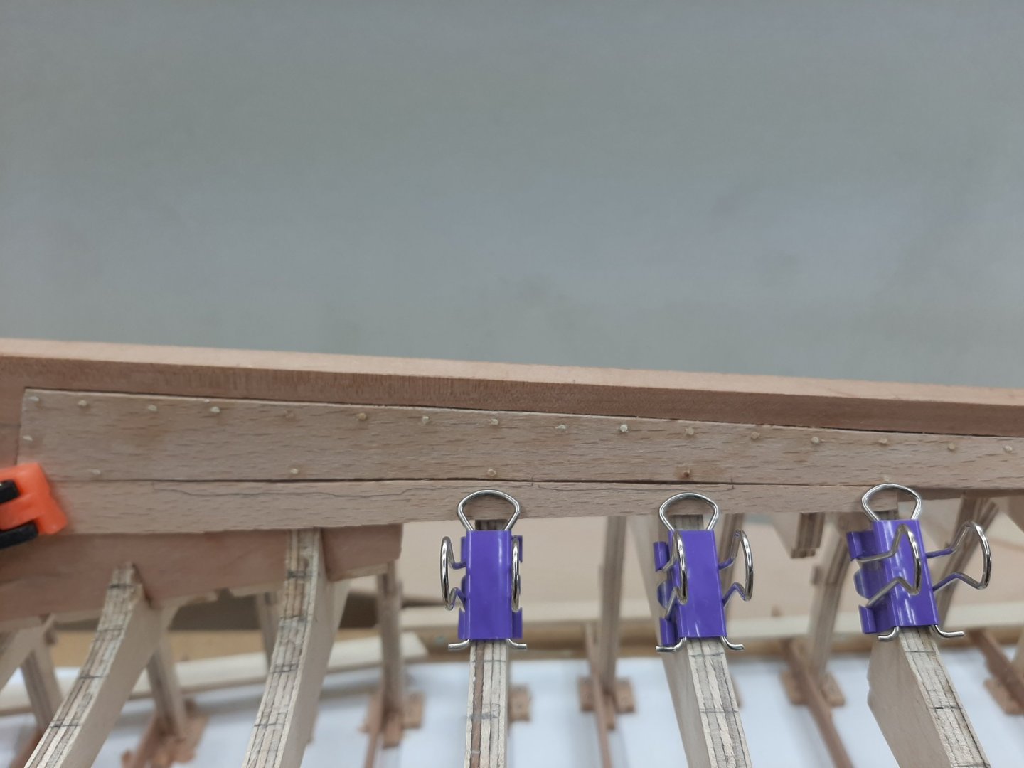
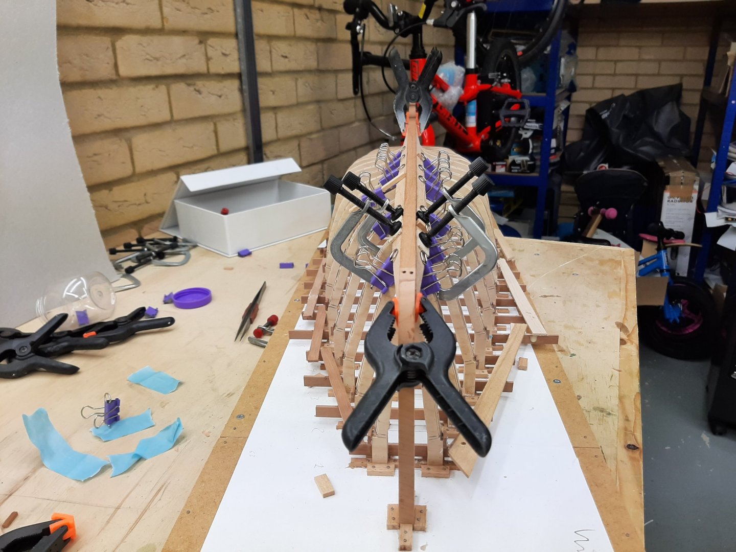
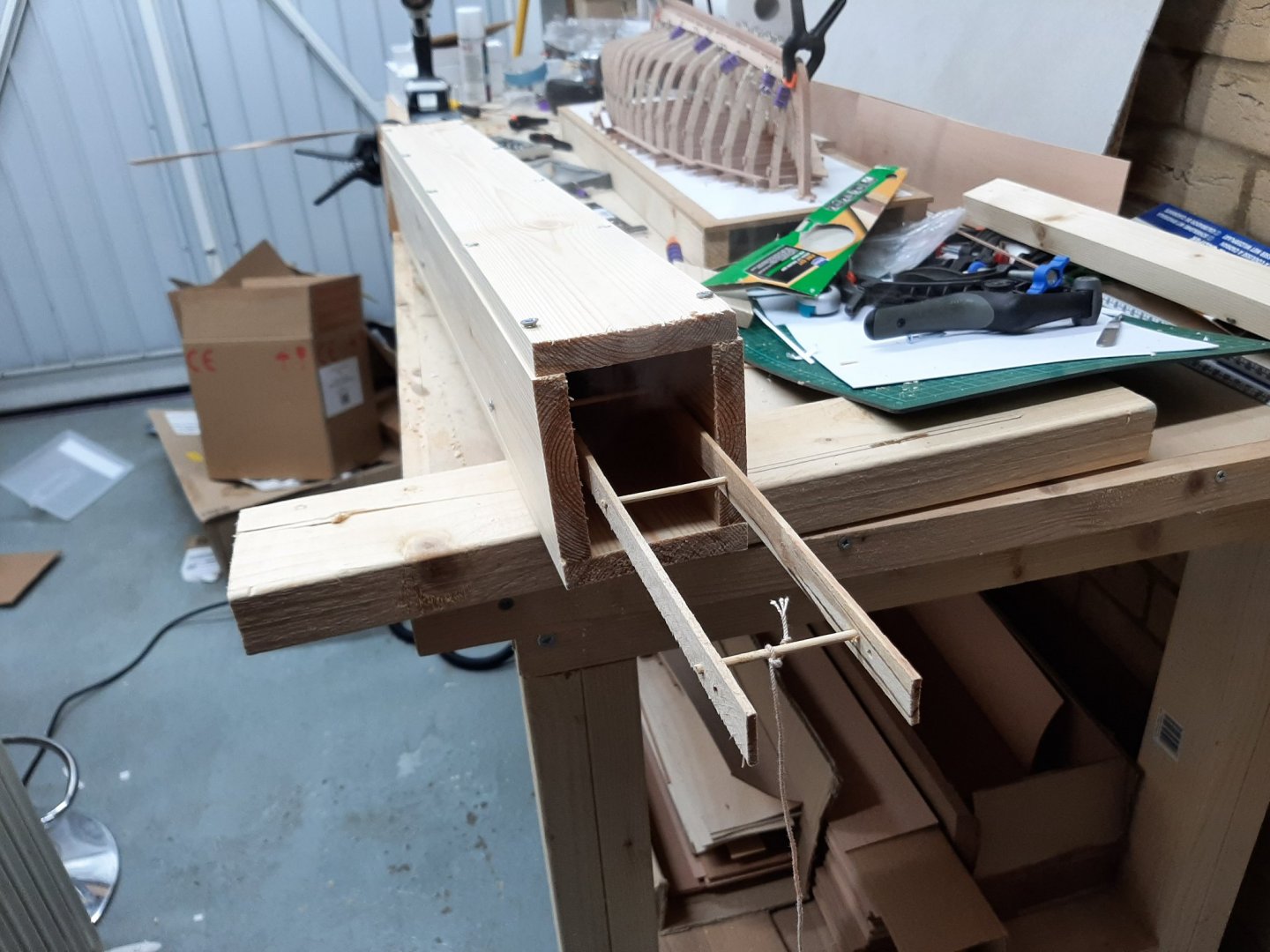
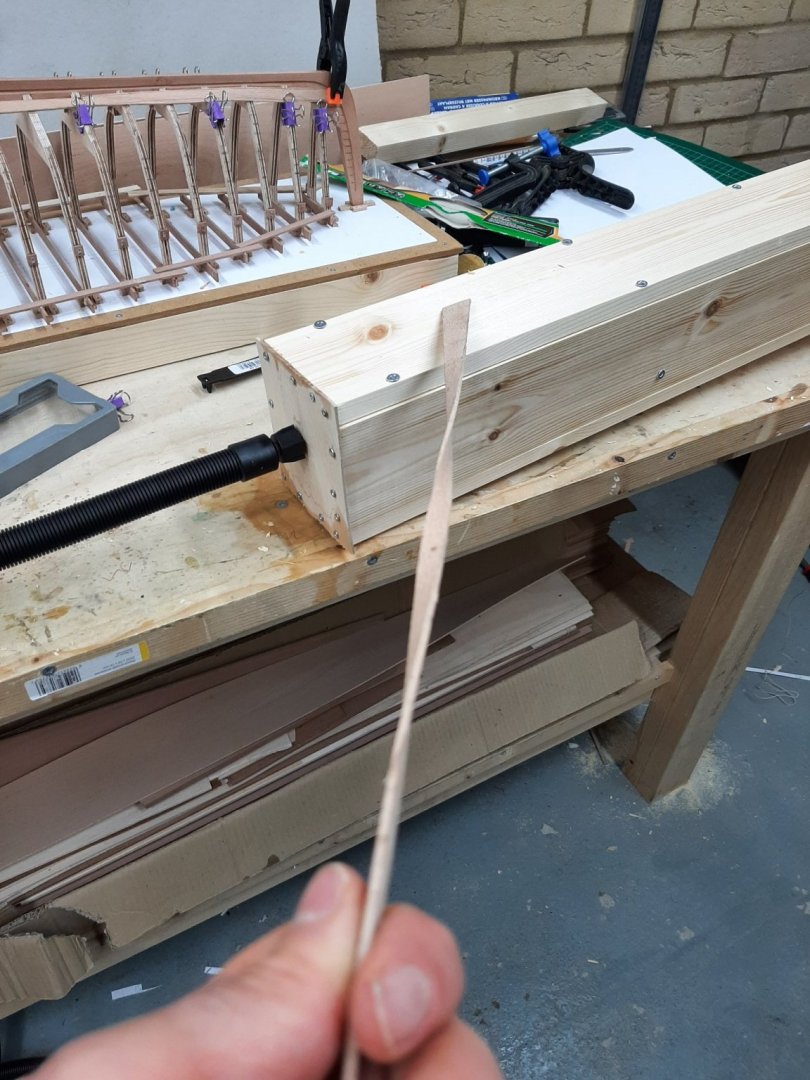
Ok, so both planks got steamed positioned into place. Definitely worth doing, they now follow the hull much closer. The next photo does not capture it well but the plank really has taken the shape of the hull. However, this means that their dimensions changed slightly. Because they sit closer to the hull, they appear slightly longer so a tiny bit of sanding at the bow end was needed. However, after I had pretty much finished screwing the planks in place, I realised that the bow end in both sides did not fit well. I cannot explain this, before steaming they were both pretty spot on. I guess this is something I ll have to live with, maybe the filler will make it look better. Now, another issue was the bow end of the planks. Clearly they do not end up at the same height. So the plank came off, sanded and re installed-this is prior to final screwing. It is better now Another area that needed attention was the joint with the stealer. In both sides the plank was sitting too low So I used a very thin shim of wood and things improved A few photos of the hull as it is now So far so good but now there is a new problem. This is actually something I had been concerned about even when I was lofting the boat on CAD. The next plank at the stern will lie horizontally but somehow will need to mate with the previous plank that lies vertical. This is the reason that I have not glued the planks so far, so I can remove if needed. So, I just put a piece of card to check things...interesting. This will need wood for the template, not card. Regards Vaddoc


-
Brian, indeed a treat to follow your build. Wonderful work! Looking forward for the rest of the journey.
-
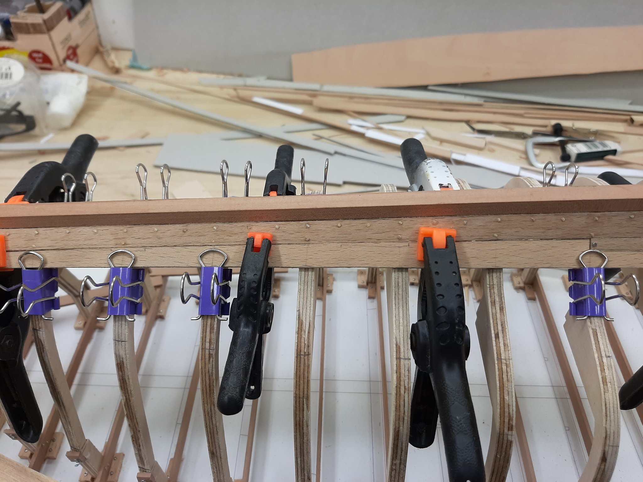
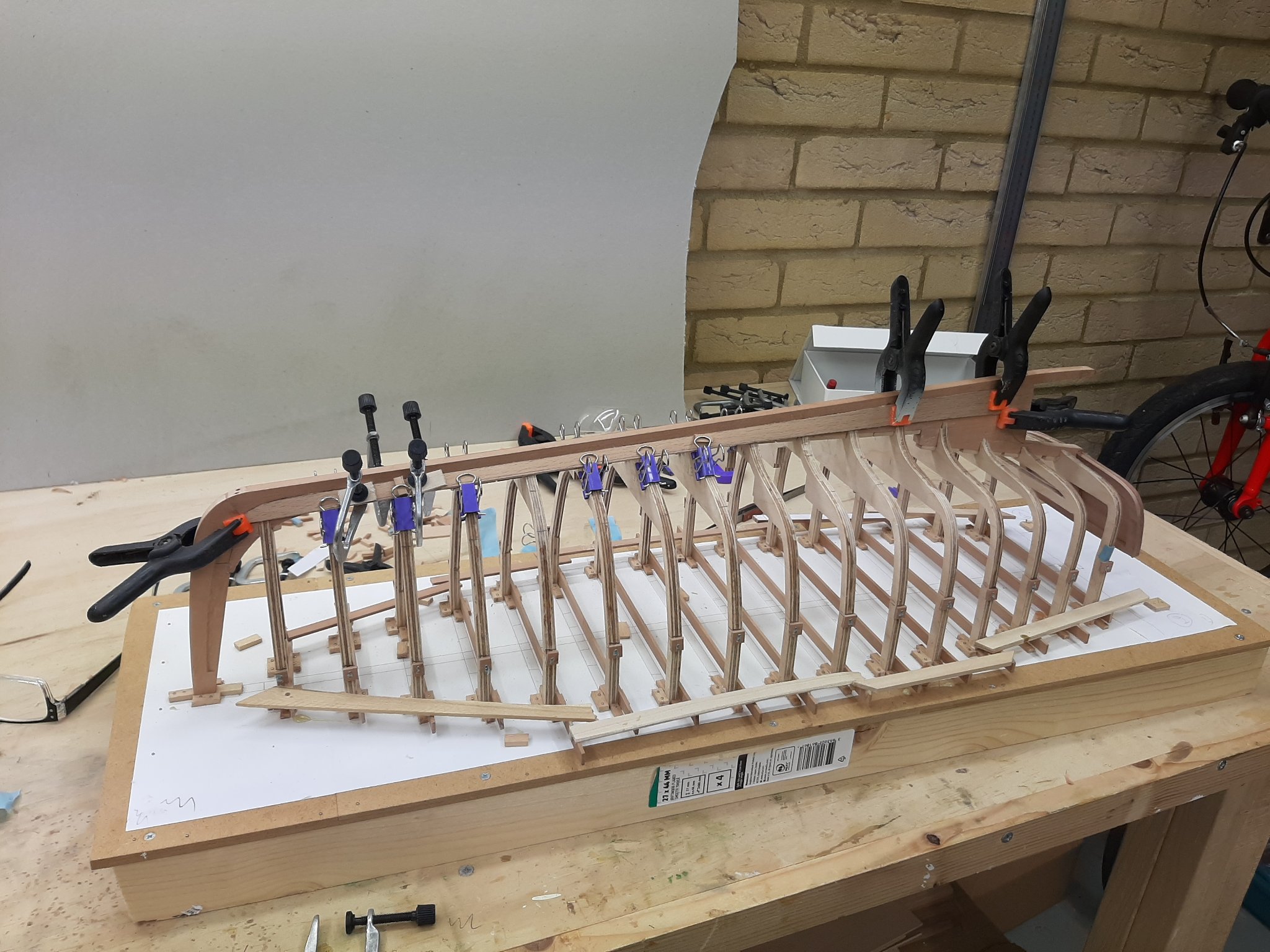
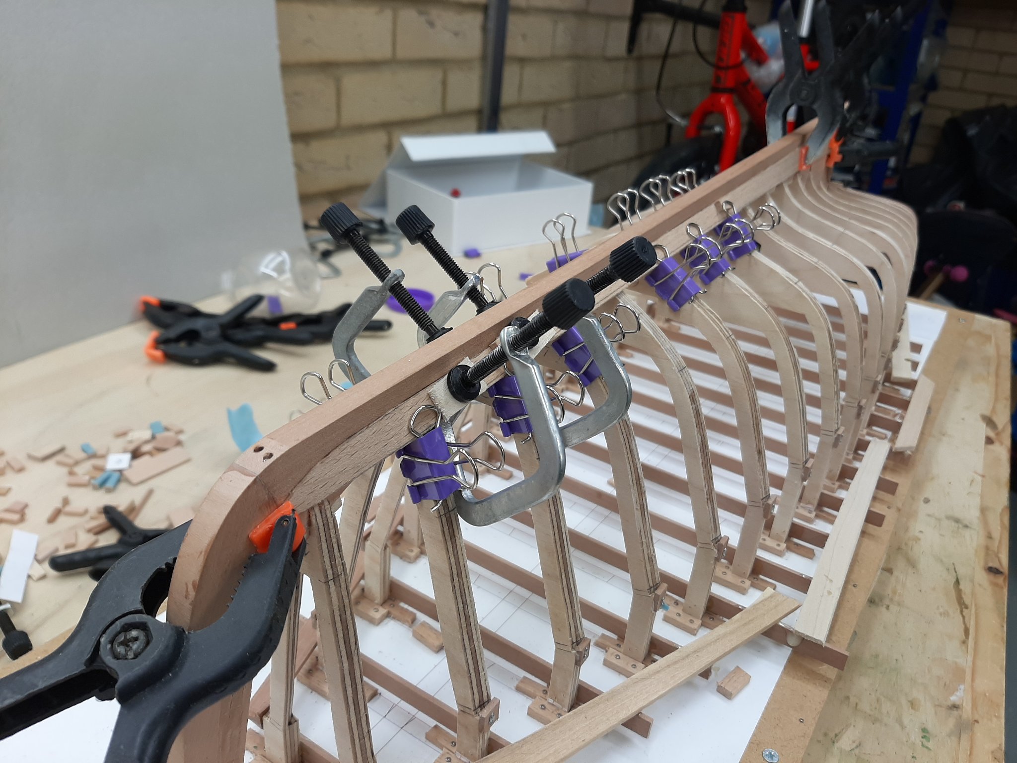
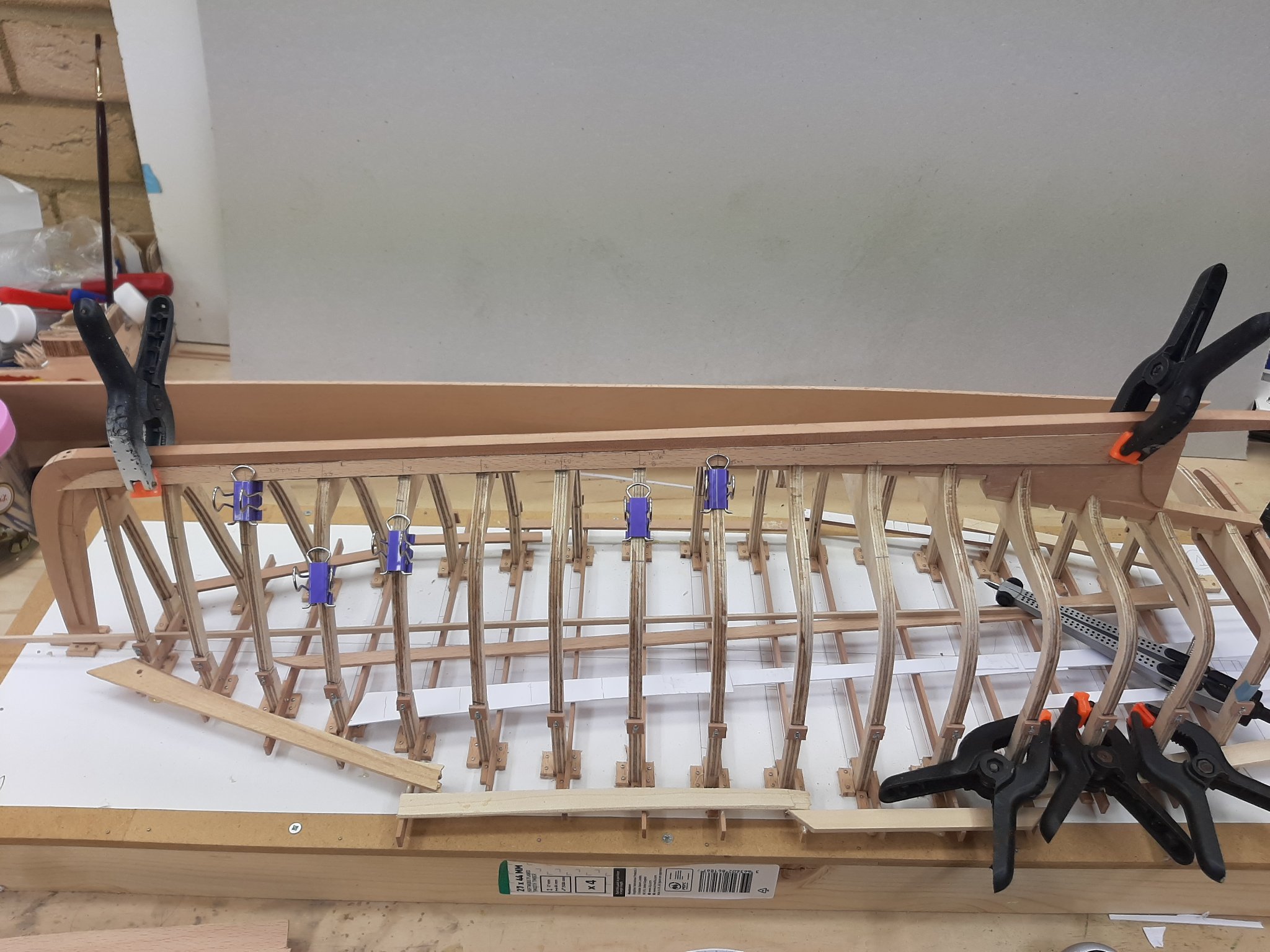
Many thanks to all for your comments and likes! GL, the planks will accept to be bent up to a point but will not accept to be twisted. This is 2.2 mm beech, a hard and sturdy wood. This plank as well as the garboard has a lot of twist, this is why all these clamps are needed-still the plank does not sit well, it lifts in the middle. Also, I do not trust the frames too much, the plywood proved a poor choice and actually I should have used more frames but I cut corners a bit. I d like to have as little pressure as possible. Even wetting the beech will drastically improve its response to bending/twisting but since I have my steam box ready to go, I ll steam the wood thoroughly-it will bend like made of dough!
-
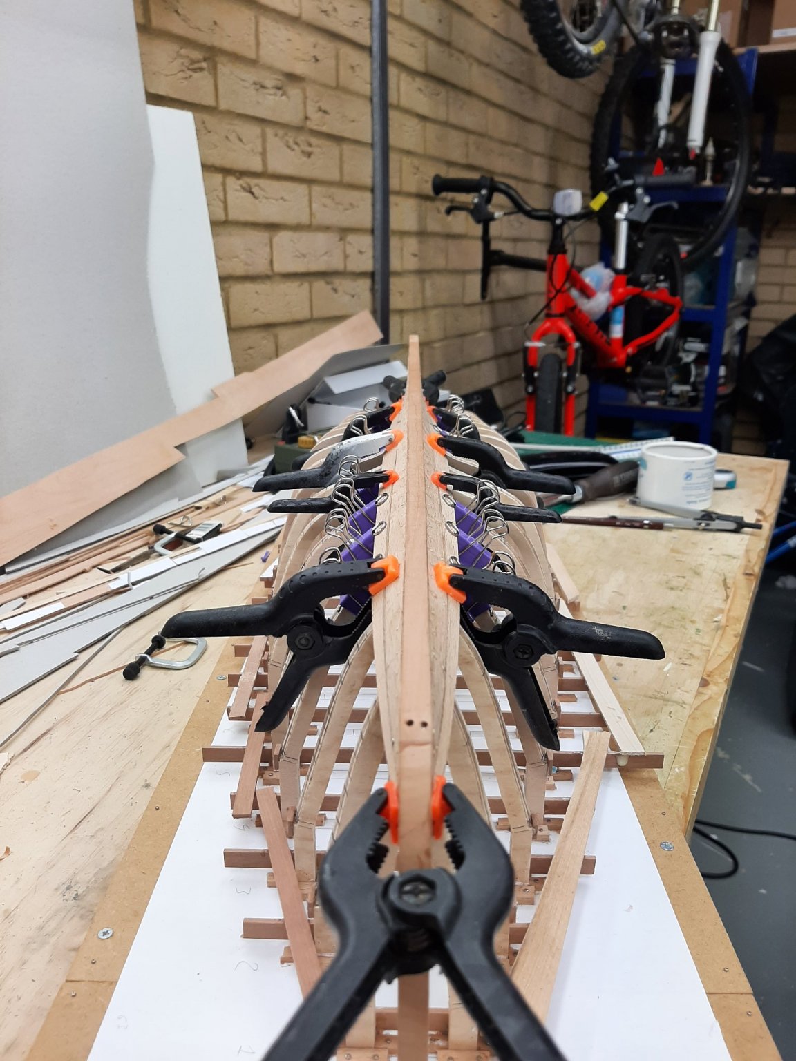
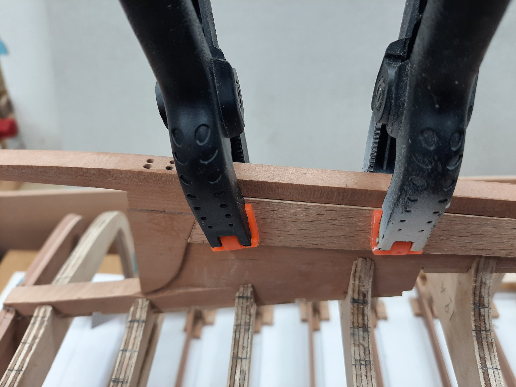
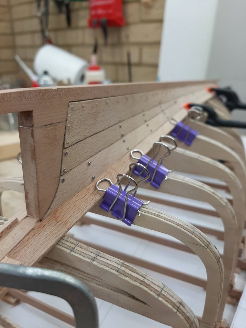
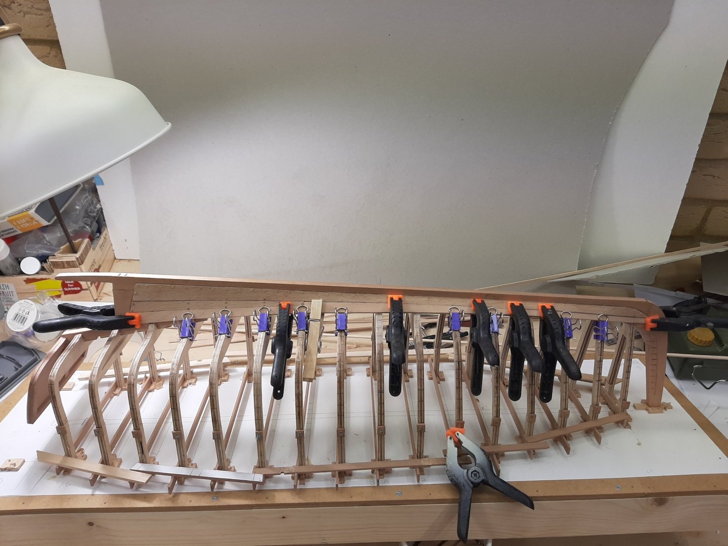
Bruce thank you for your kind words, it is certainly worth it. After countless attempts, the starboard plank is done but I am a broken man! I ve never had such difficulty producing a plank. It is however a very complex shape and due to the twist along its axis both at the bow and stern, even tiny changes in the shape or even the width of the plank, bring on massive changes to the fit. Some photos to show the end result-both planks were difficult but the starboard one almost defeated me. The planks can be edge bent a little so the gaps will close further. That was more than enough for today. Tomorrow I ll steam the planks and install them again with screws. The reason is that while this plank finishes vertical at the sternpost, the next one will finish horizontal an the transom so at the stern, the two planks will meet at 90 degree angle. Maybe some adjustments will be needed but I will not know until I start work on the next plank. Regards Vaddoc
-
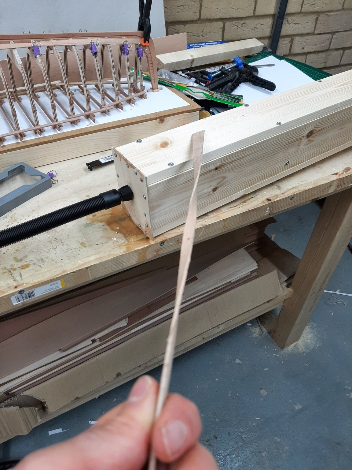
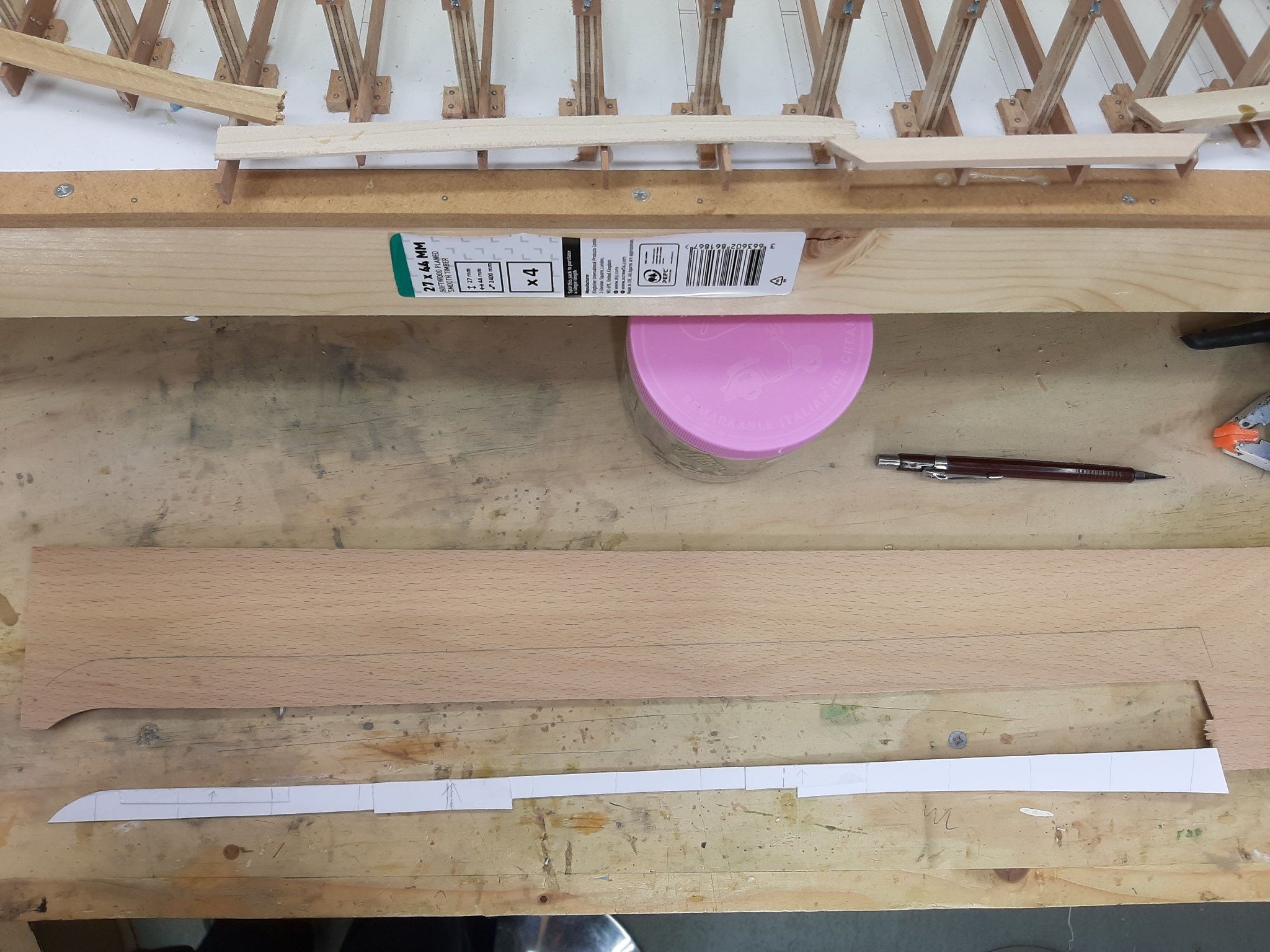
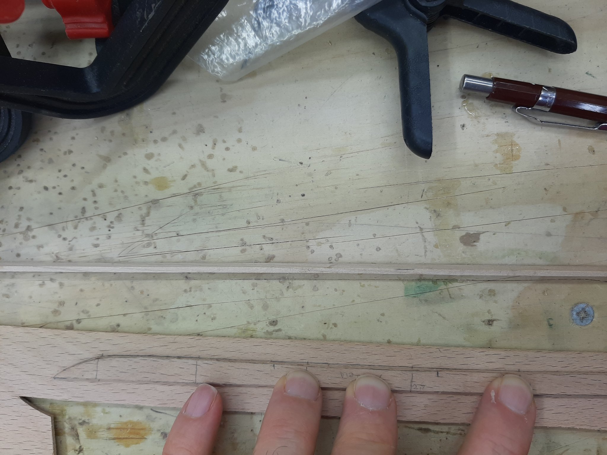
Time for another post, unfortunately not a lot of progress as I run into difficulties. Moab and GL thank you for your kind words, a pleasure to have you on this journey! After infinite trouble, I managed to produce a half decent port plank. I think I made 3 templates and 4 planks, thankfully the last one was acceptable. This is by far the most difficult plank. It has a significant twist, it needs to fit with the stealer, it is long and narrow towards the bow and it is very easy for the paper pattern to distort. But I also now need to make the starboard one. Again, I immediately run into the same problems. After a few failed attempts, I decided to use 2 mm thick cardboard and then to use shorter segments. Finally, I ended up with a promising template. I marked the other edge of the plank measuring from the sheer, to make sure one side mirrors the other. This is the outline of the plank on the sheet. Incredibly, it is almost identical to the port plank Ya...right. It did not fit! This is properly difficult. Another issue is that despite using a very sharp knife, the blade still follows a bit the grain so the cut edge is a bit wavy. Honestly, I believe that cutting a full scale plank should be easier. So, I ll use this failed plank to make a new pattern and try again. I am a bit concerned I do not have enough wood, provided my next attempt will be successful I will have used a whole 100 x 1000mm sheet to make just two planks. However, the rest of the planks should be easier to make. Vaddoc

-
I must confess I am having too much fun! Risking the Admiral's wrath I did some work today. First I installed the two stealers. The port plank I steamed and fitted was a rejected version, somehow it sneaked in and replaced the correct one. I realised this and found the correct plank on the work bench. I just soaked it in water for a few minutes and then the plank easily bent into position. I just temporarily screwed the planks in place in case they need to be removed to deepen the rabet. Next, I started making the template for the first broad strake. I was very careful not to edge bend the paper. Again, I am only interested in the upper (bottom) edge that meets the garboard and stealer, the other edge will be defined later. This was the result. The plank is 55 cm long - they will get much longer. Note that the plank is almost straight, as were the garboard and the stealer. So far the initial planning of the planks seems to be working. Then, I measured and transferred the distances at all stations and connected the dots with a fair curve. I also cut the paper template to roughly the shape of the plank, I think it looks ok. It is 23:00 in England so I called it a day, cutting planks is a delicate job. I should have ordered twice as many beech sheets, I was very conservative in my initial estimate of the wood needed, there is the potential for a lot of wasted wood. Vaddoc

-
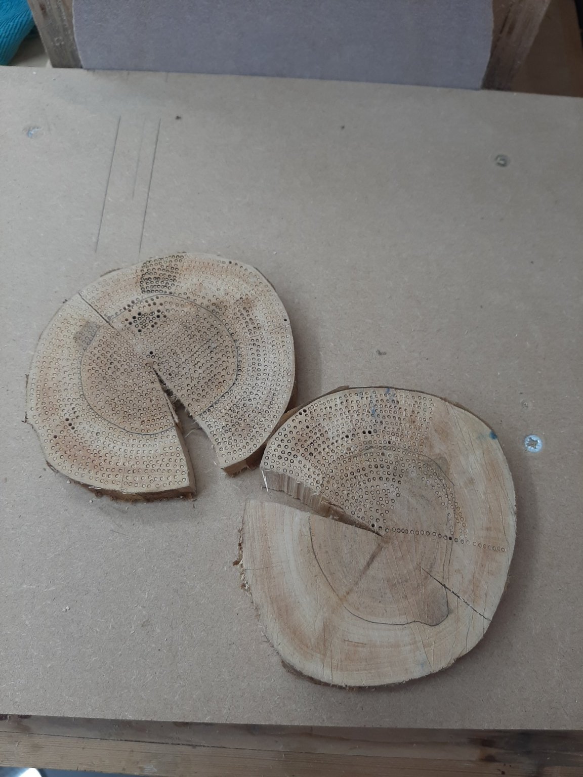
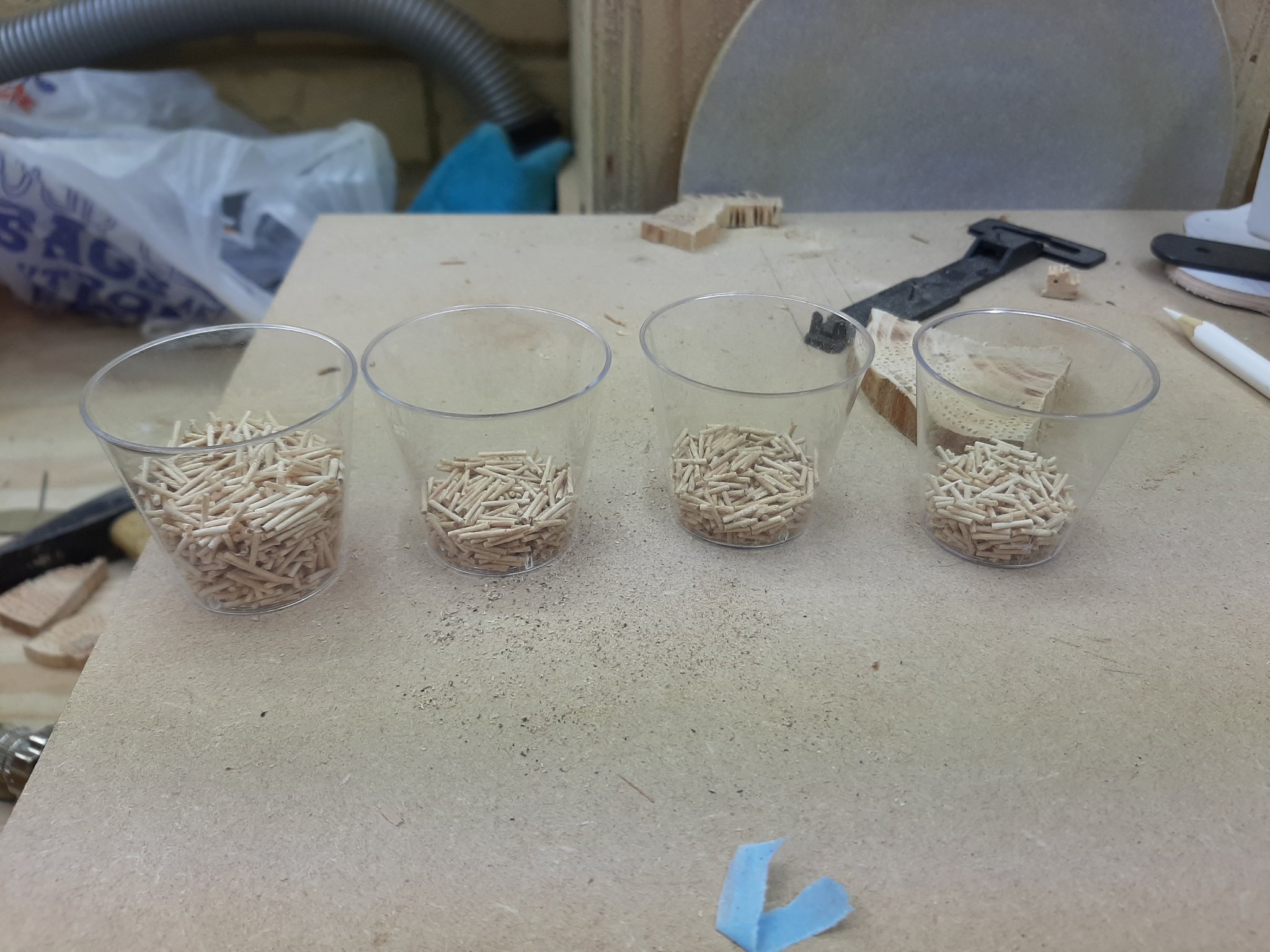
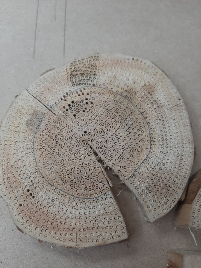
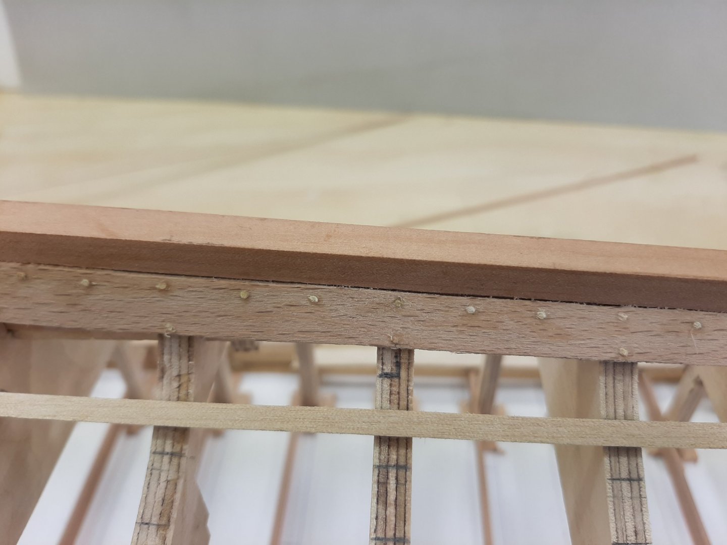
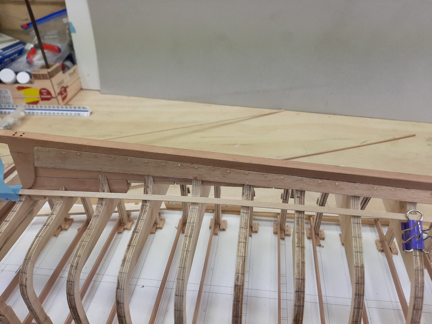
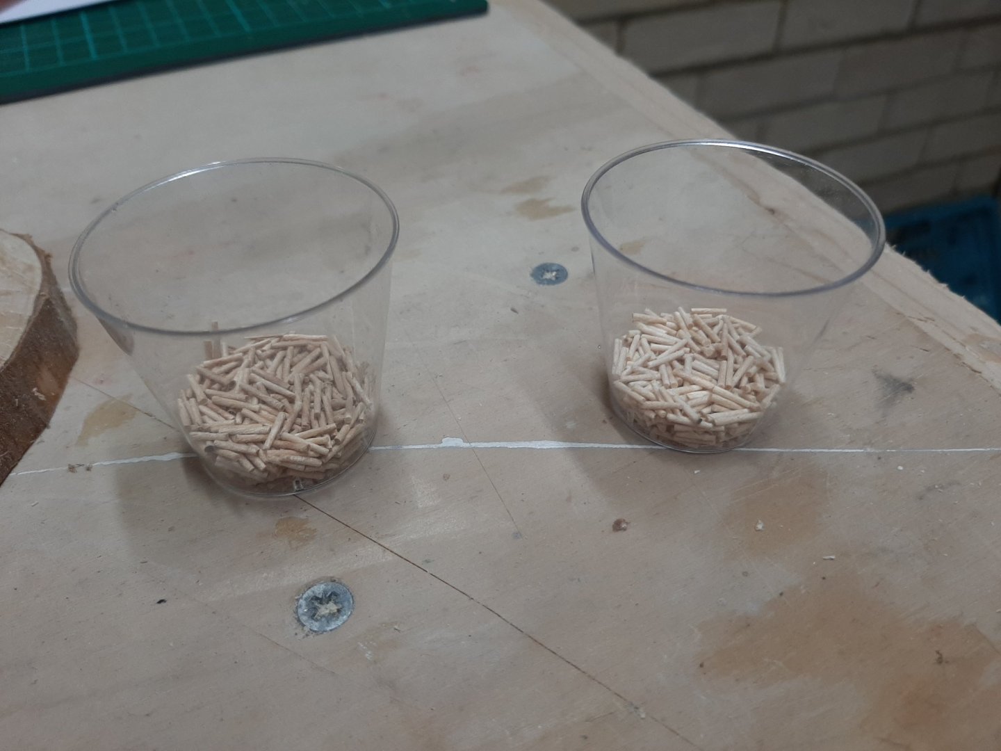
Tree nails, thousand of them. They can be made in bulk down to 0.6 mm or even less. These ones are 1 mm thick, in these pots there are about 1000 tree nails. The pieces can be positioned accurately and securely.


-
Looks fantastic Hakan. This dark shade really lifts the model, I like it a lot. You could consider using treenails for those stringers, would be more secure and easier than glue. Now, if I could take a guess, is your next boat a pilot cutter?
-
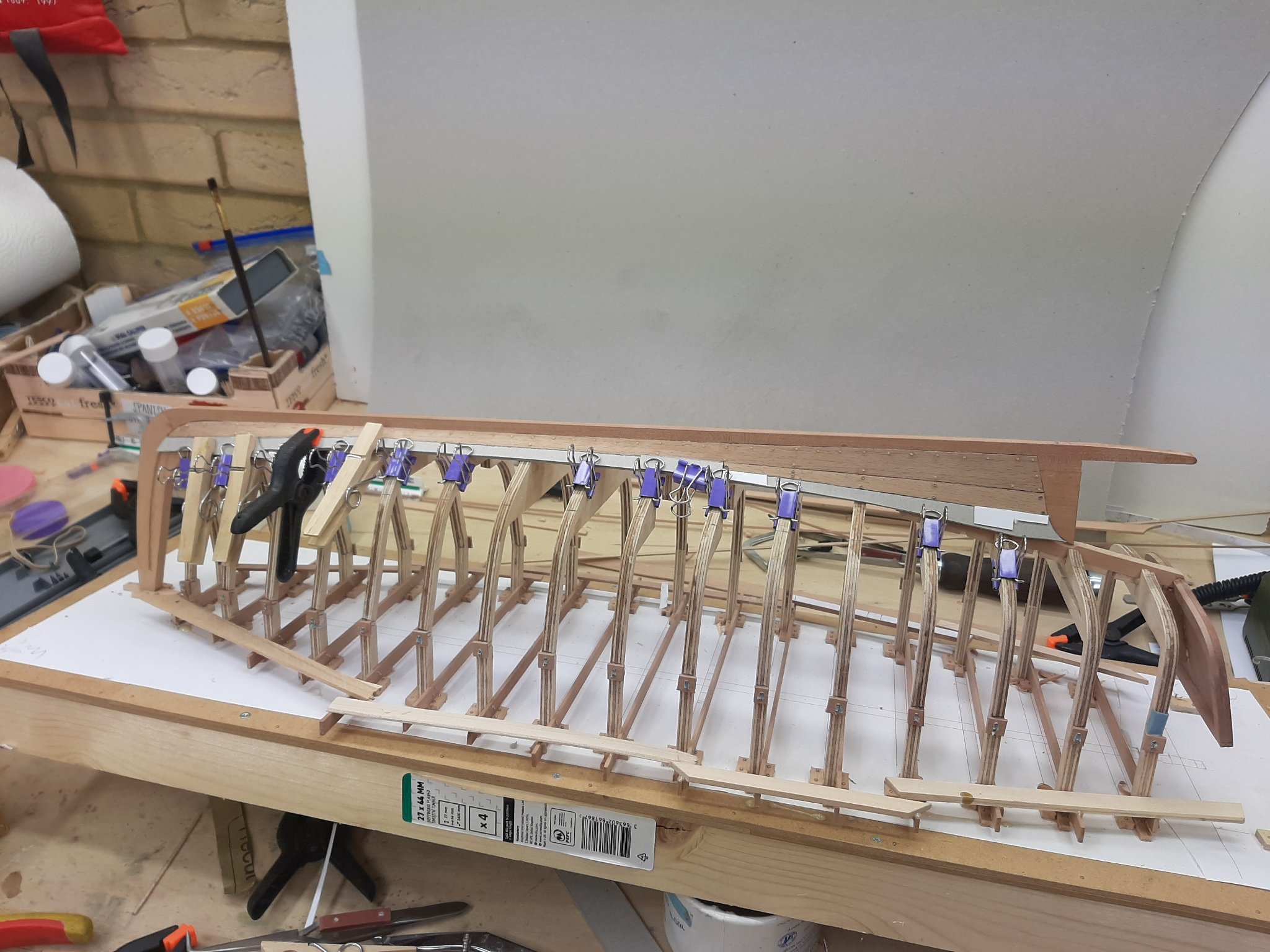
Some more work done, time for another post. I installed both garboards, even after steaming some pressure was needed to get them fully into position. Initially I used 1 mm screws to keep the planks in the correct position and then gradually replaced with treenails. I had to deepen the rabet, at places quite a lot. I am not too happy with the bow end of the port plank, it should be spot on but now there is a bit of a gap. Oh well, a bit of filler never did any harm! Then I moved on to the next plank which I think should be the stealer. So, first a defined the shape that the first broad strake should have. This plank, up to a point, it follows the edge of the garboard but at some point it deviates and this is where the stealer starts. The stealer will not have a pointy end but a square one which will sit within the first broad plank. So things should look something like this: The position where the two plank ends meet should be here Then I laid a baten to define a fair upper edge for the stealer However, when I cut the plank template it does not look right. It seems it needs shortening by one frame. So that is what I did. It looks much better now. I had to make sure that the first broad plank, which now will be longer, will not be too wide for the curve it must negotiate but it looks fine. Ten I cut the stealer. With a bit of adjustment, it fitted fine. Now, at this point I was curious whether this plank would fit on the other side. It should, as the upper edge of the garboard should be finishing at the same point at all frames in both sides. Well, it does! Then I made the other stealer which also came out fine So all looks good so far. However, today I remembered some more planking tricks and tips. It is coming back to me as I progress. After the plank is cut, minor adjustments can be done by scraping the edge of the plank with the knife. It works like a plane. But also, again using the knife as scraper, the other edge of the plank needs to be "planed" into a fair curve to make it easier to mate with next plank without gaps. Further more, the plank can be cut with the scroll saw to just out of the line and then with the knife plane down to the line. For this to work, very sharp blades are needed so I change mine very often. Regards to all Vaddoc


-
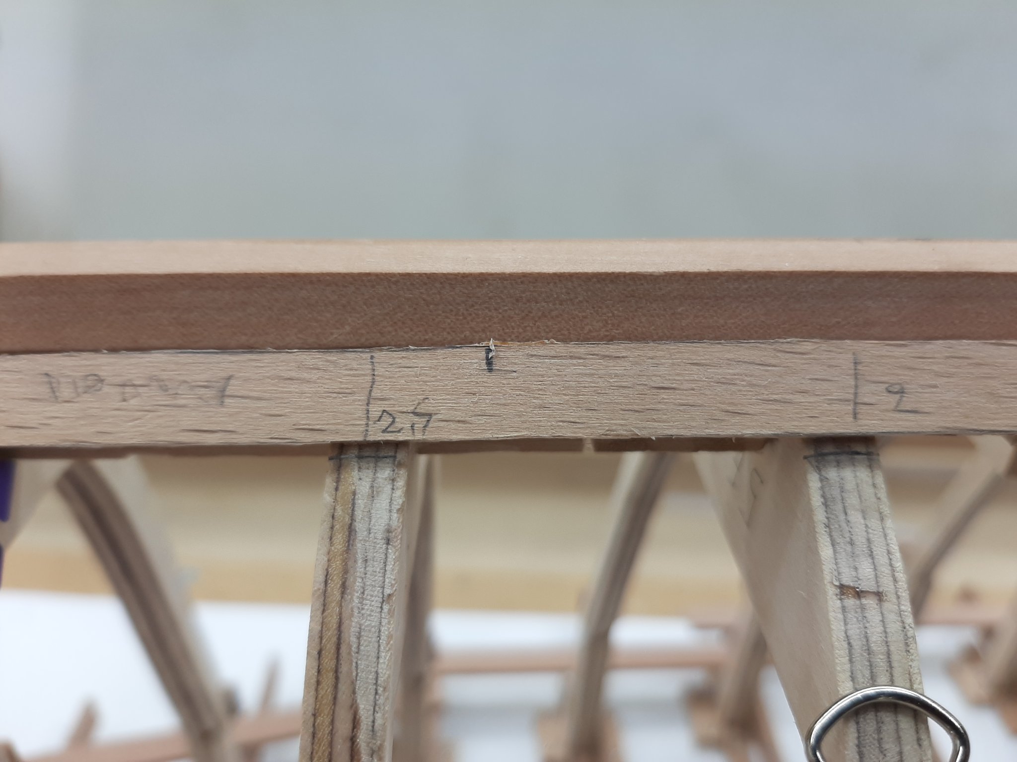
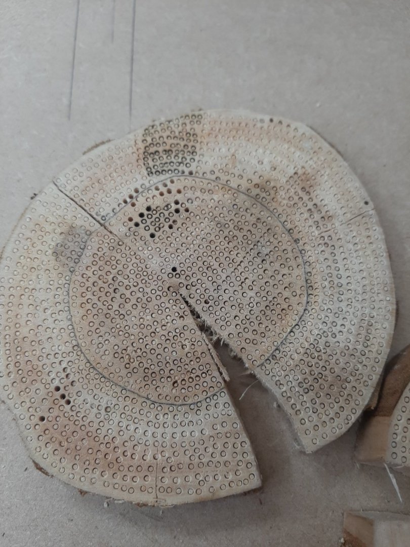
Jim and to everyone that hit the like button, many thanks! I think time for another small post. I ve been thinking how to attach the planks to the frames, for the Yawl I ll use threaded brass wire but I do not think this will be possible for this boat, I do not trust the plywood frames to hold the threads securely. So I am thinking of using treenails, like I did with the Deben. I think I ll need 1500-2000 (including wastage) for the outer planking alone so I sat down to make them. I used the needle method, in the past I ve made many thousand of treenails. I used a small log a friend gave me a couple of years ago, I am not sure what tree it came from, either hawthorn or hornbeam. It is a hard and strong wood though. It took a while to make things work, I kept burning the wood but with a bit of trial and error I managed to get things working. I cut thin discs and drilled the tree nails. Then I sanded the back and released the nails. The heartwood was very hard and the sapwood at areas seemed to have deposits that clogged the needle. I was not too happy with the first bunch, they were quite short. I sorted the nails according to colour, I ll use the lighter ones that are more plentiful. The darker ones are from the heartwood, denser and stronger but even the lighter ones are very strong. In the next photo they don't seem a lot but actually they are more than 800. Then I sat down and made a few more, this time longer and better. This time I made close to 2000, so I should have enough to start planking. So time to steam the planks! The garboards are the more difficult to fit, the twist of the plank is significant and really the clamps are difficult to be positioned securely. My steamer worked brilliantly and despite taking a long time to fit the plank so that it cooled down halfway through positioning, it accepted the twist just fine. I need to deepen the bevel in a few areas but otherwise I am happy with the outcome. Tomorrow if possible I ll nail the planks to position but I need to think of a way to make sure all the nails align across all planks and that are spaced equally. Vaddoc


-
How about mixing epoxy with brass dust (sold on ebay) and then just touching the outer end of the 0.4 mm wire to leave a blob of 0.8 mm.
-
Is this helpful? https://www.amazon.co.uk/Prym-0-60-Straight-Brass-Pins/dp/B0027IZTP4/ref=sr_1_1?dchild=1&keywords=Prym+0.60+x+14+mm+25+g+Straight+Brass+Pins&qid=1613847521&s=kitchen&sr=1-1
-
How very nice! Indeed, these details have made a world of difference. This is a fantastic model GL.
- 86 replies
-
- 1
-

-
- whaling
- clinker built
- (and 2 more)
-
I have decided to build a steam box.
vaddoc replied to Osmosis's topic in Modeling tools and Workshop Equipment
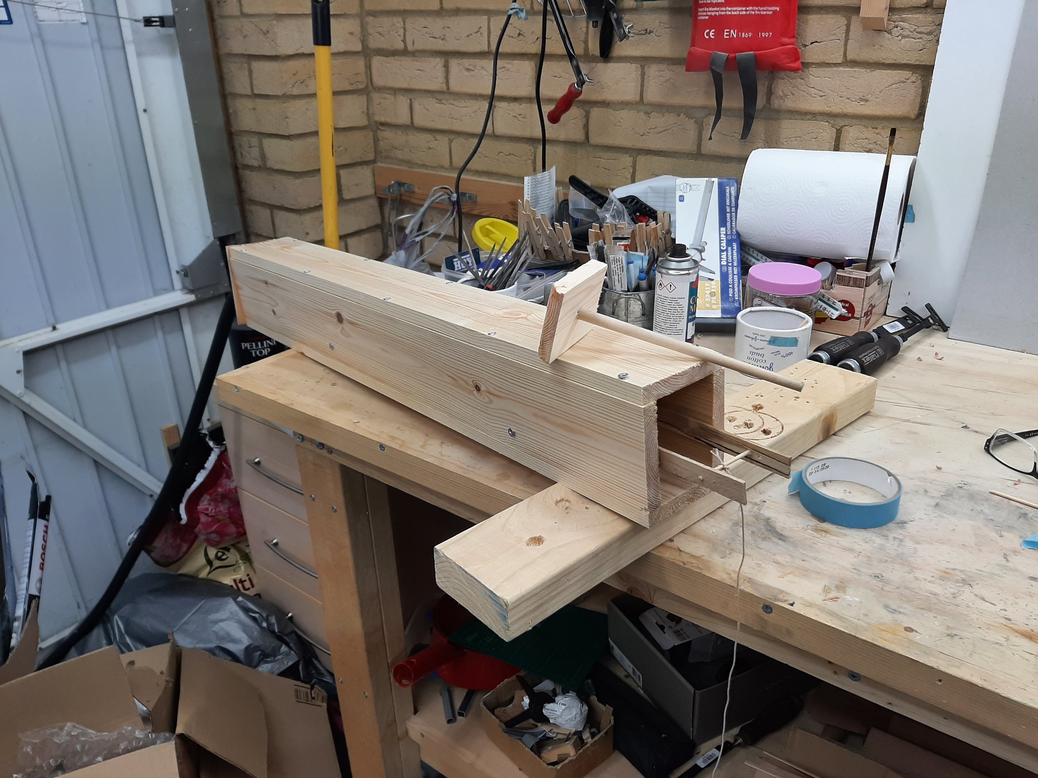
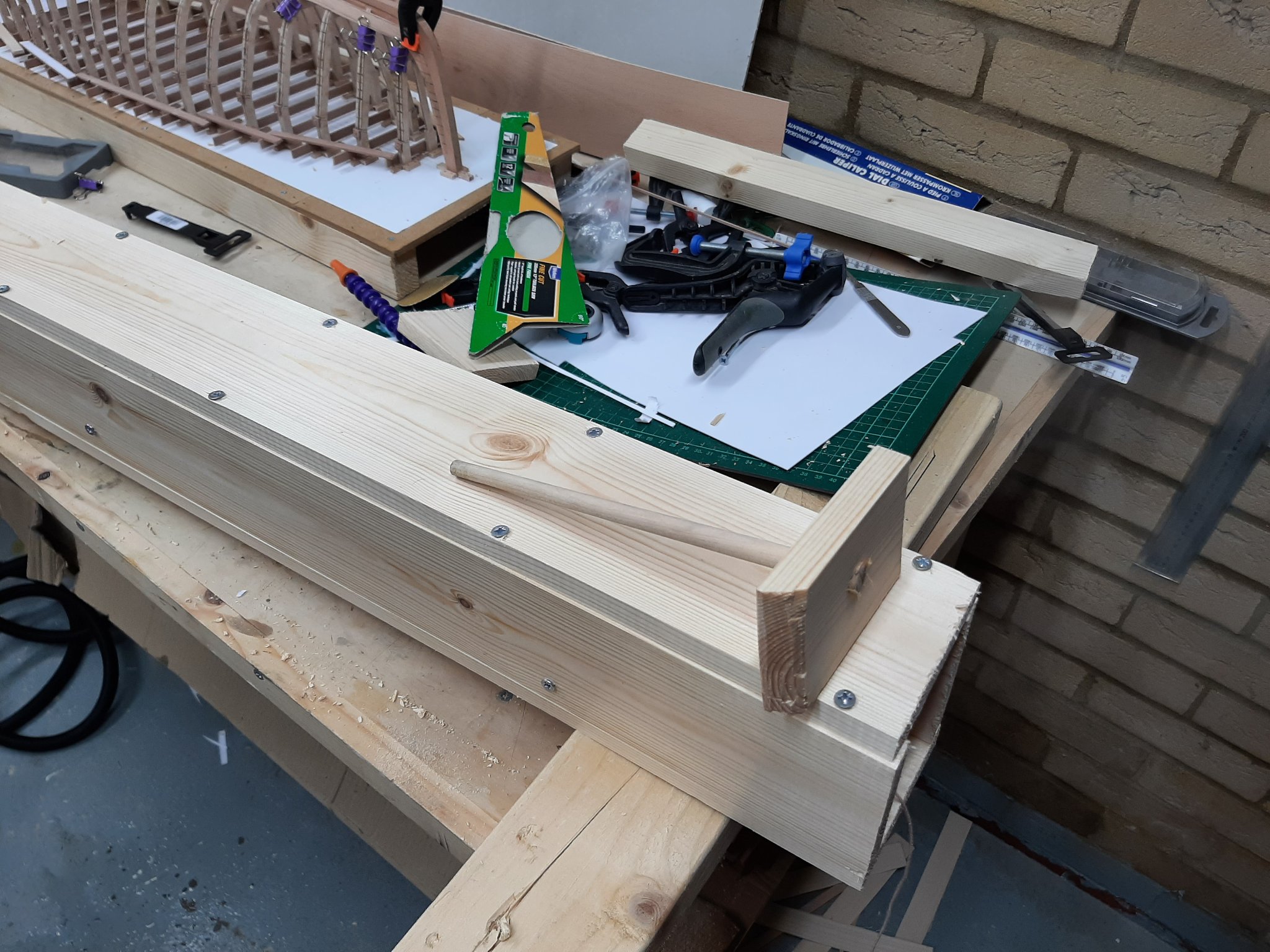
Well Art, I got motivated by your thread and built my version of a steam box. Dead easy to make, tried it today, huge success! Materials (This side of the pond): 2 planned wood planks from B&Q at £9 each and a wallpaper steamer at £30 and scrap wood. I did not put a drain hole, the water drained from the (not so) closed end. The door was undersized so that steam could escape. After 2 min of steaming, the 2.2 mm thick beech planks could be tied to a knot!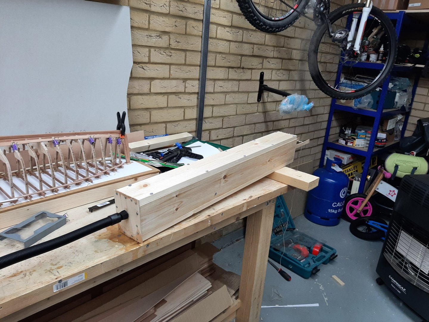

-
I converted form soft solder with a heat iron to silver solder. I use the Proxon torch which is excellent. Silver soldering needs parts to be very clean and in contact but at least for me is more controllable and easier to work with. I use phos solder paste so when polished it does not stand out against the brass parts. I could never control the soft solder in the same way-strength is a non issue. In regards to equipment, it really depends on the scale you work and how large and thick the pieces are. If the pieces to be soldered are large, a powerful iron is needed to deliver the energy to raise the temperature. If they are too large, it may not work. Even with silver soldering, I had a few large pieces to solder and the Proxon torch was not adequate-I have a much bigger torch for these. Any of the irons you ve looked at will do the job.
-
Looks good George! What is the sea made of?
-
Some more progress so time for another post. Many thanks to all for your likes and comments! Now, in the previous post we have cut one of the garboards so next task is to cut its sister plank. This was much more difficult and more complicated than I expected. The two sides of the hull are not as symmetrical as they should or could be. The garboard I ve cut will not fit on the other side. I am not sure what is the issue, I think the rabet is not cut at the same height in a few areas but everything else looks ok. Still, it will not fit. I marked the frames to determine where the new garboard should reach and using a paper template I cut the new garboard. The plank did not come out right. There are unacceptable gaps with the rabet and at places it is not wide enough. Using the plank as template, I filled the gaps and then with a compass measured the widths again but this time used a different baten to connect the dots, a 2x2 mm pear strip. This time the plank looked better. It actually looks better than the first garboard! On the boat, the two garboards look identical but put on top of each other, their shape is similar but they do not fully much. But it also true that even tiny variations in the frames will massively affect the curvature of the planks. The next photo shows the first plank, the gaps are a bit larger but nothing terrible. I think also the rabet is not deep enough, I wonder if it would be simpler to sand the plank. They are actually a bit thicker than 2 mm. The work will now need to stop, I need to make a steamer device to steam the planks. Also I need to add some wood to the horn timbers for the planks to rest on. Vaddoc


-
I have decided to build a steam box.
vaddoc replied to Osmosis's topic in Modeling tools and Workshop Equipment
I was thinking solid wood planks or better sacrificial plywood but maybe PVC pipe is the way forward.