HOLIDAY DONATION DRIVE - SUPPORT MSW - DO YOUR PART TO KEEP THIS GREAT FORUM GOING!
×

.jpg.f26acc9a74319261612561bfa7da1303.jpg)
vaddoc
-
Posts
1,600 -
Joined
-
Last visited
Content Type
Profiles
Forums
Gallery
Events
Everything posted by vaddoc
-
.thumb.jpg.6fd4c1b78768bb3efd745ab810936005.jpg) Very nice work Brian! I ll bet on black (for the bottom colour). Your log is very interesting, looking forward for the rest of this journey. Have a wonderful Christmas and a happy new year! Vaddoc
Very nice work Brian! I ll bet on black (for the bottom colour). Your log is very interesting, looking forward for the rest of this journey. Have a wonderful Christmas and a happy new year! Vaddoc -
Gary, echoing the other comments, a wonderful model. Fantastic work and a very inspiring log all together. Have a wonderful Christmas and a happy new year! Vaddoc
-
Yes, I use a strop and green compound too. Brings the metal to a mirror shine and a few passes, when the chisel shows reluctance to cut wood with ease, restores the edge. To save time I strop freehand.
-
I am no woodworker but I am slowly appreciate how accurate tool a well sharpened chisel can be. There is a learning curve in using a chisel and much more so in honing a chisel. The first chisels I got were from Aldi, the ones that chap Sellers says are brilliant. They do the job I must say. However, I got a 4 mm Narex which I ve always thought was better. Two days ago I received a couple more of the Narex chisels, a 3 mm and a 6 mm. I spend a bit of time honing them and used them today. My impression is they are easier to hone, they get sharper and they hold the edge longer than the Aldis, overall a better tool but the difference is not massive. I may just be imaging things though. In any case, I just ordered an 8 mm one. I believe that all modern branded chisels have good enough steel. However, to maintain a razor sharp edge, a chisel needs constant honing and from time to time reshaping. This part is I think even more important than the quality of steel. Honing stones in various grits, a honing guide and a jig to allow the chisel to be positioned always at the same angle on the honing guide is needed. Get the Narex, you will not regret I think and very good value for money. I also have an expensive Ashley Isles V chisel but have not used it yet Hope this is helpful Vaddoc
-
Keith, it did not work at all. The size of the tool is fine and it is powerful enough. I think the problem is the small length of the stroke. To remove material, 100 grit or less is needed. The size of the sandpaper particles at this grit is large. The head of the pen sander vibrates around 3 mm (or so), not enough to effectively sand and remove material. I experimented a bit but it is simply the wrong tool for the job. At least I did not have to pay for it as I used some Amazon gift vouchers I was given. I now carefully chisel the bevels (and occasionally my fingers). Power tools are too aggressive and files end up rounding the bevels. Not easy! Regards EG
-
A quick update The keel has come a long way but of course there is more work needed. It is not glued together yet, I need to think how best to do it. Shaping the inner bevels of the frames is proving to be a difficult and very time consuming job. It would be nice to have some kind of power tool, small enough to fit in and be controllable but also powerful enough to sand away the 6 mm plywood. I bought the Proxon pencil sander, it hope it will make the task easier but really I do not have high hopes. I will report when it arrives.
-
At some point consider having a go making your own rope walk and rope. It can be made inexpensively from whatever left over materials or things bought cheaply. It is an art on its own and great fun.
-
Maple is a fantastic wood for planking. Not as hard as beech and pear but holds an edge, superb in bending, easy to work with. Minimal grain, white-ish. If you like the colour, you will not regret.
-
Also check Arkowood. They seem to select the timber they send out quite well. I love beech. It is hard and tough, holds an edge, glues well, sands well, bends fantastically well. Good for frames, planks, keel. Does not split like walnut. I am going to plank two boats at 1:10 scale with it. I like it looks and colour although the pattern is quite prominent. A couple of things though. The wood pattern depends how it is cut, can be elegant little dots (usually) or wide spots (not very nice). Also, wood seems to vary from tree to tree (I know, big surprise here...) I received some beech recently that seems much harder than wood I bought in the past. If you like the looks go for it.
-
Just catching up Brian, the stove came out great. What paint did you use and did you use any primer?
-
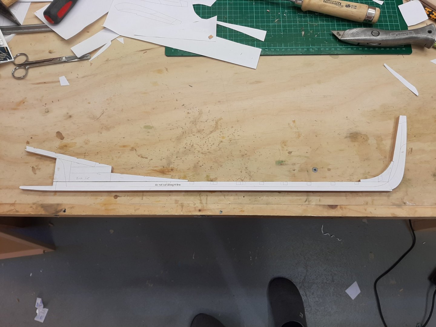
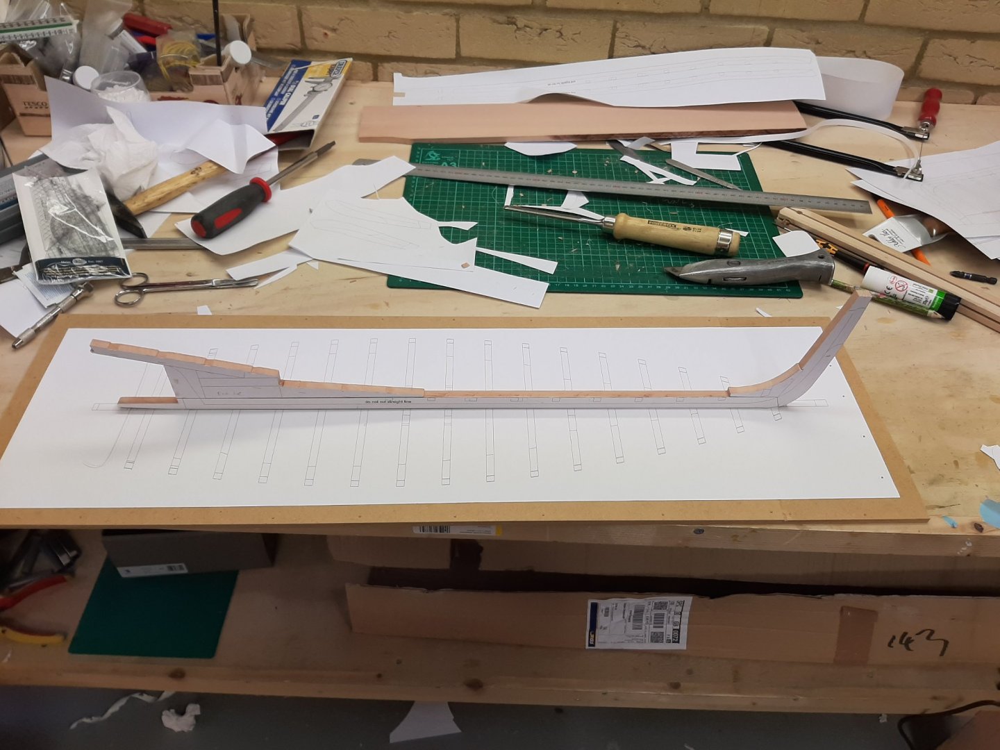
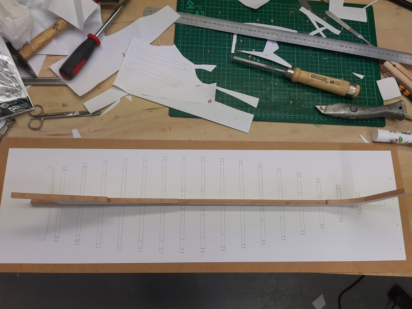
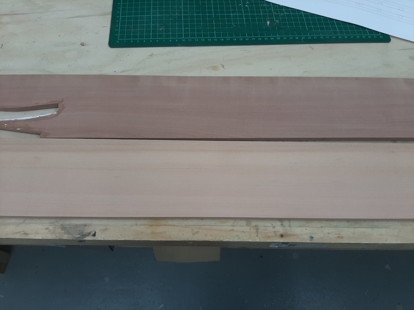
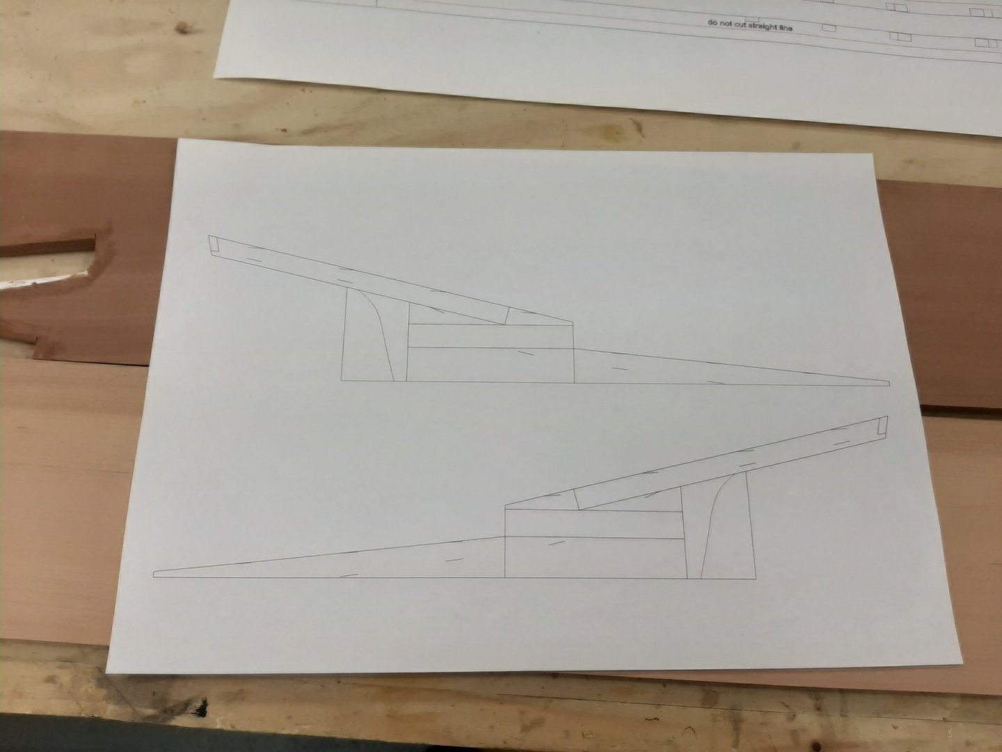
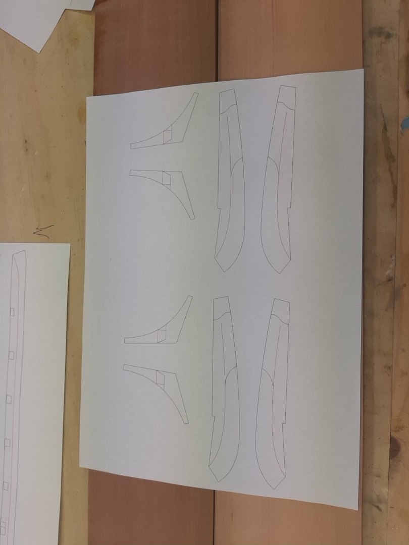
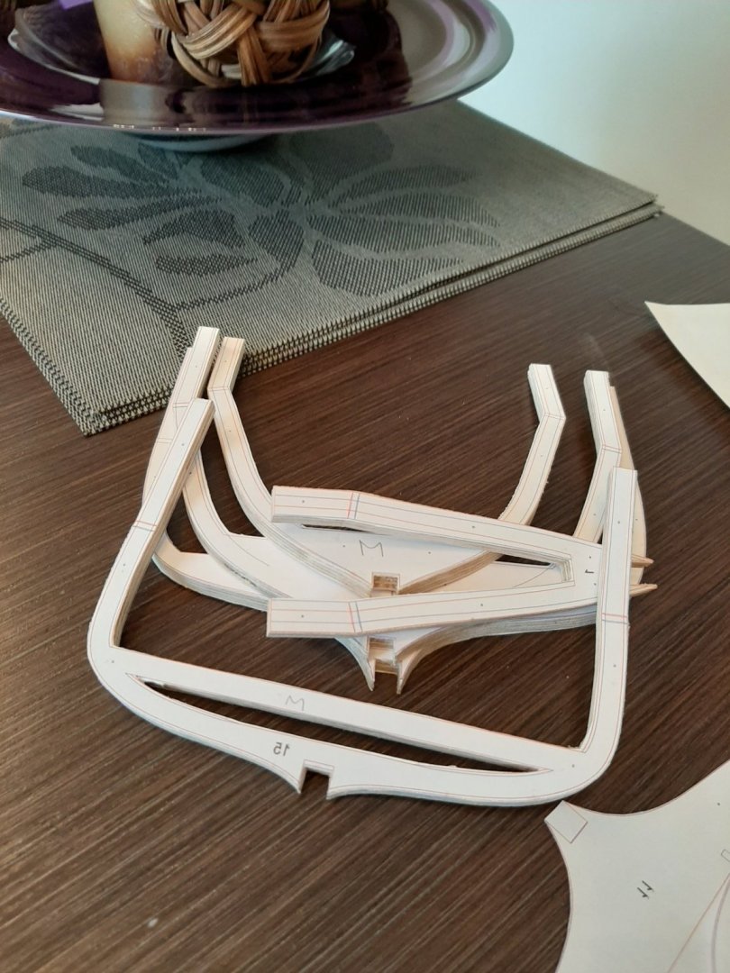
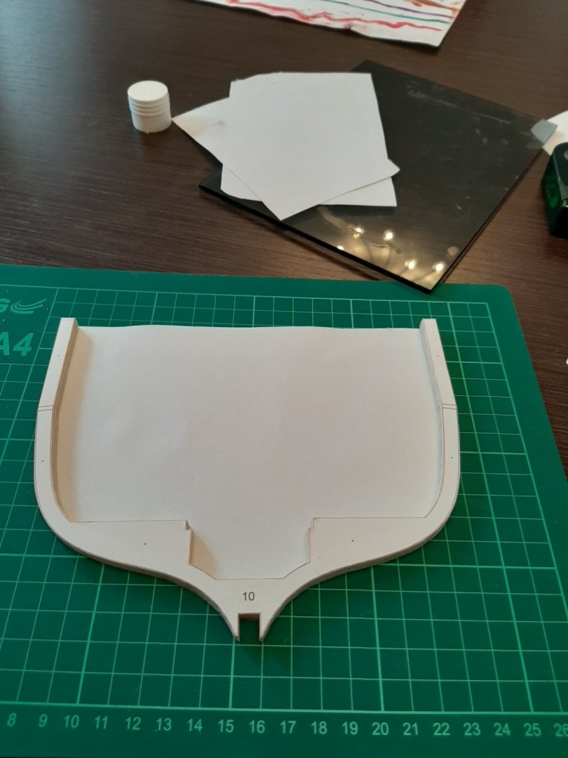
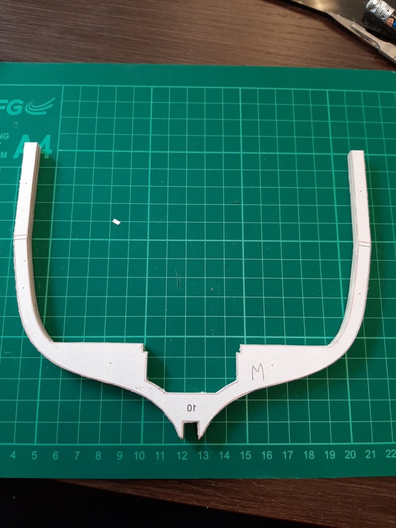
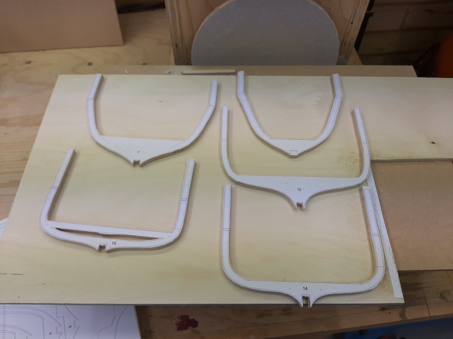
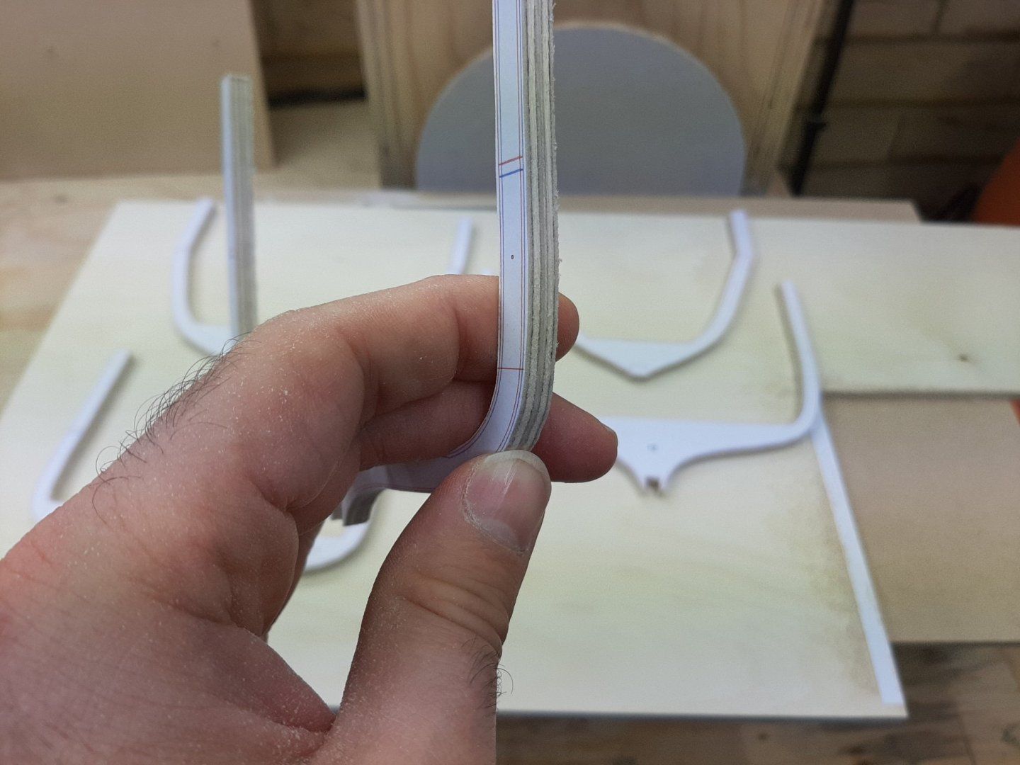
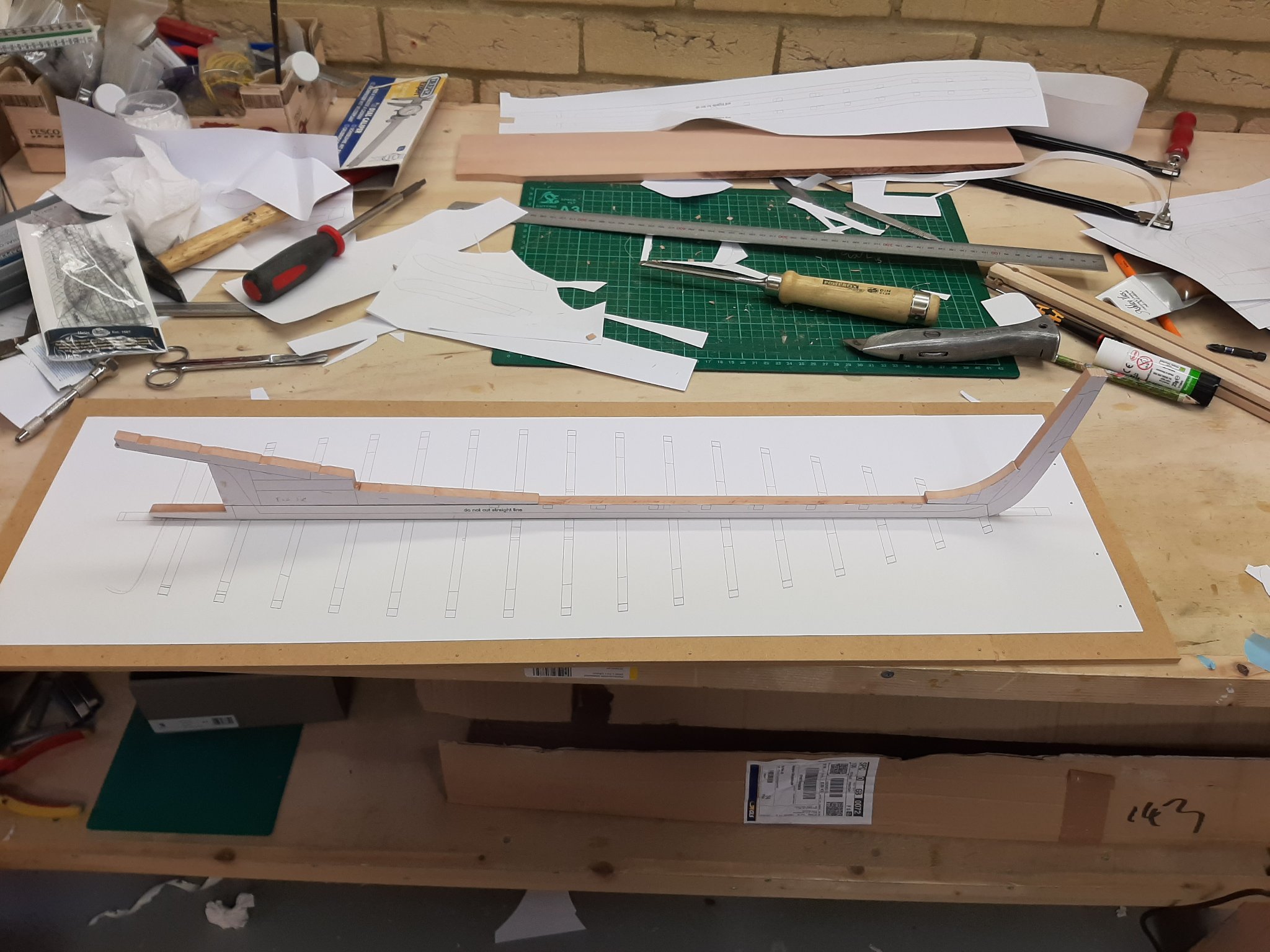
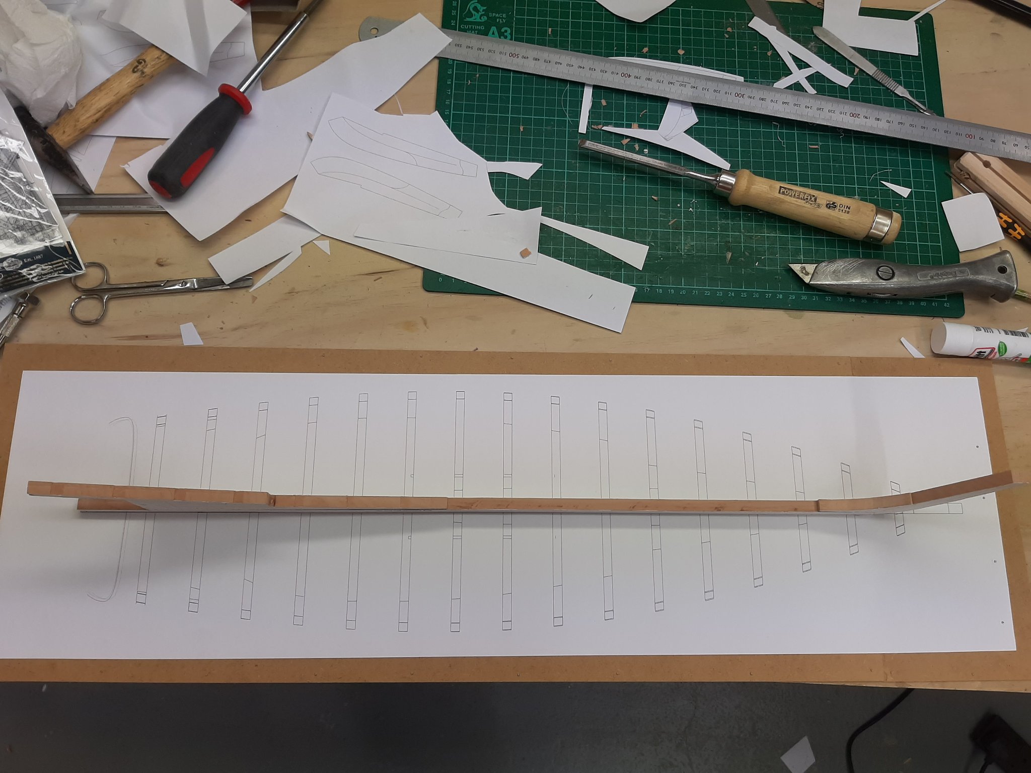
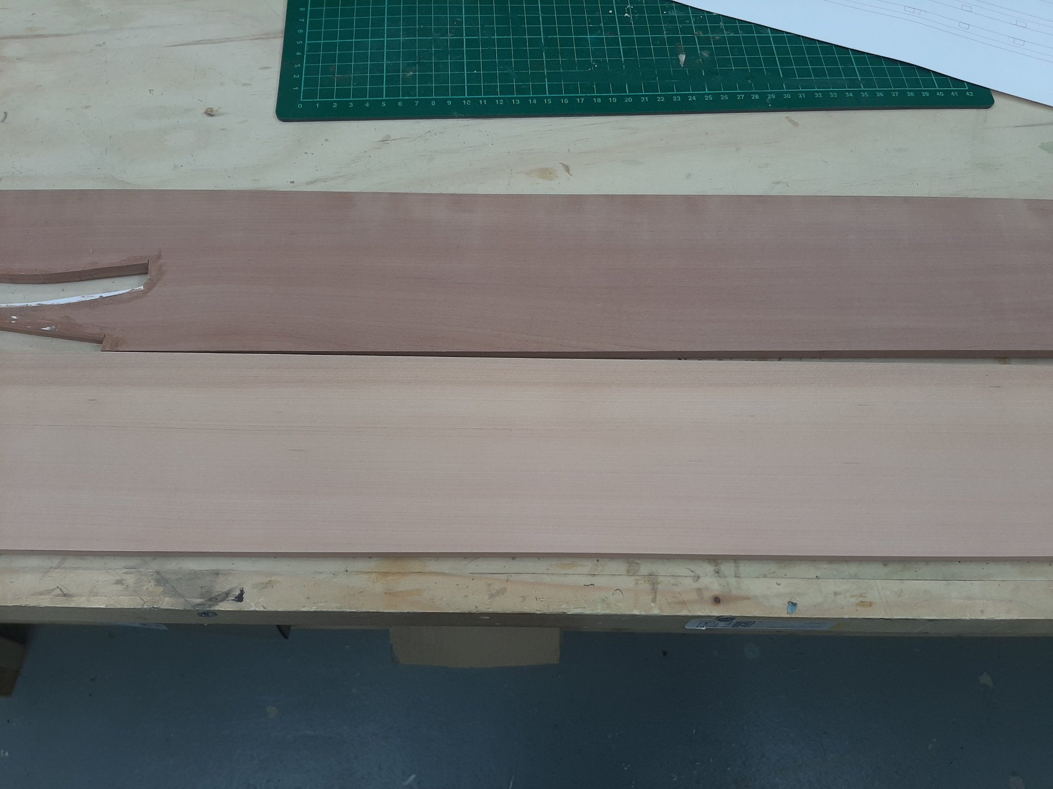
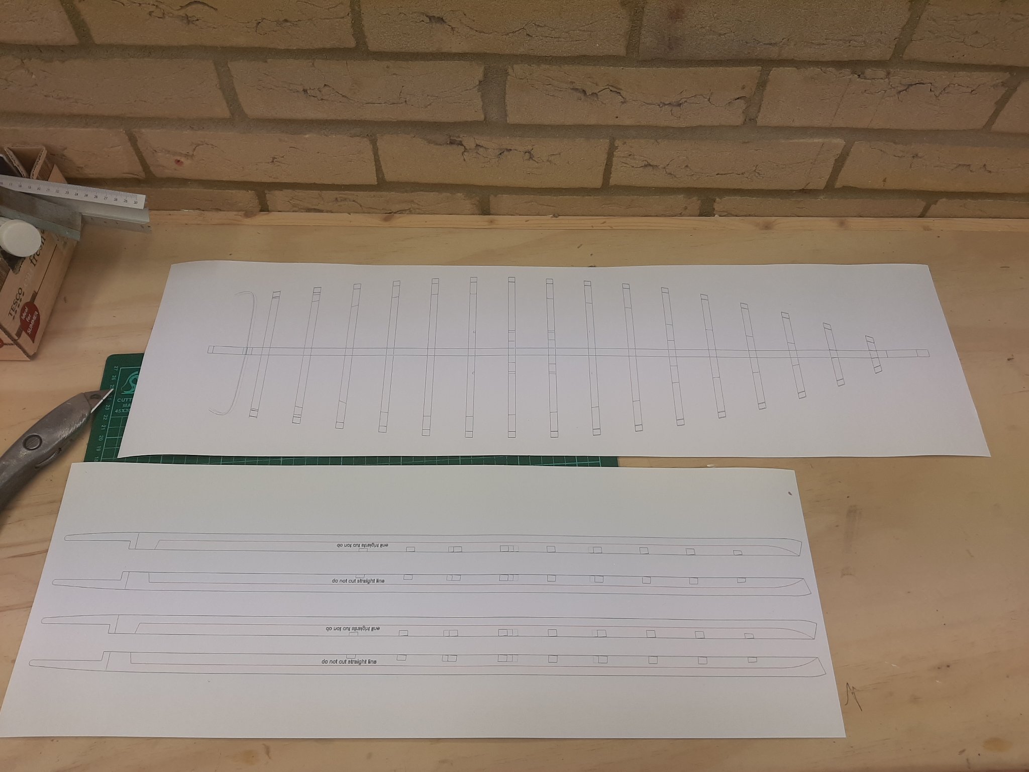
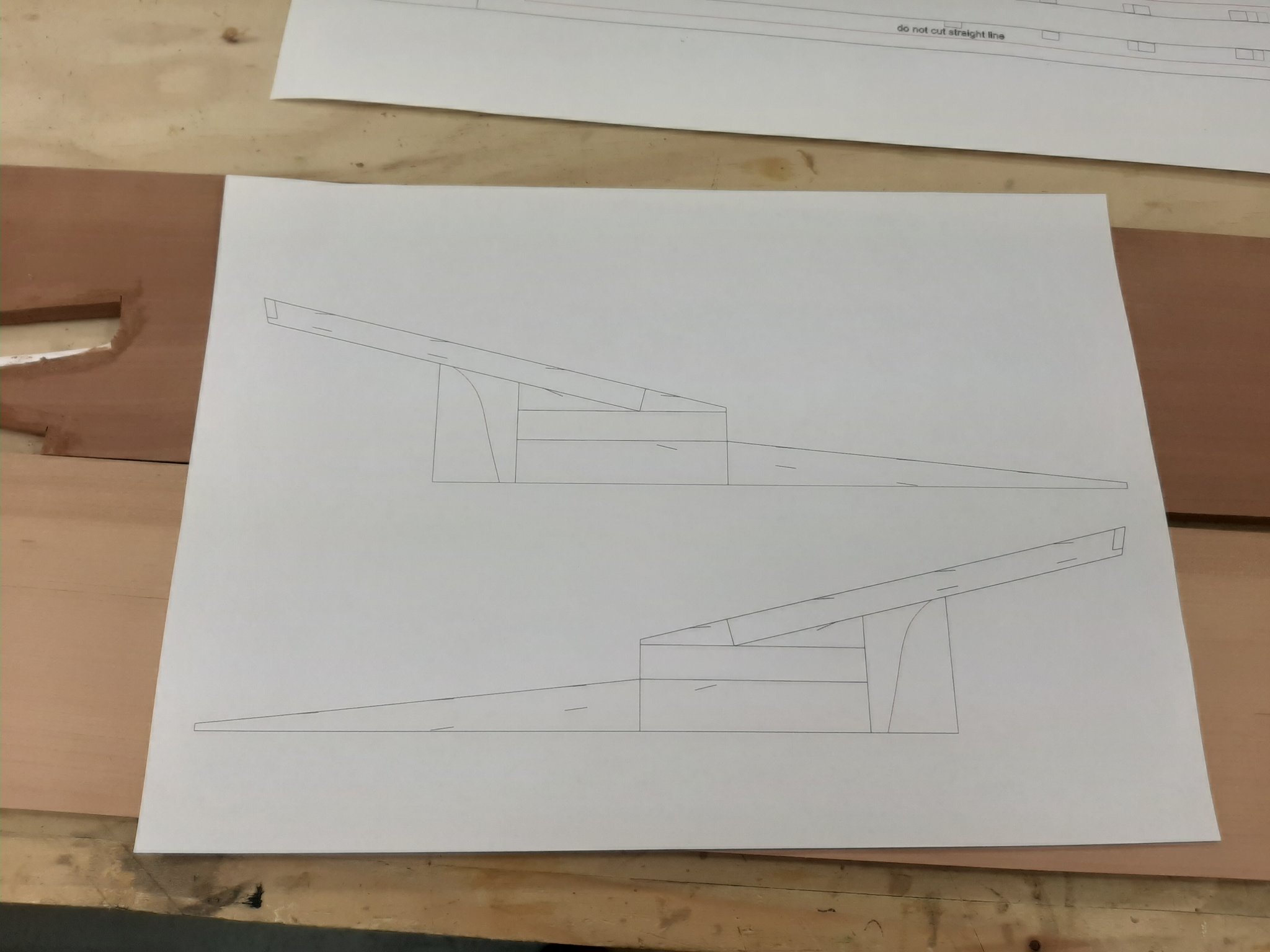
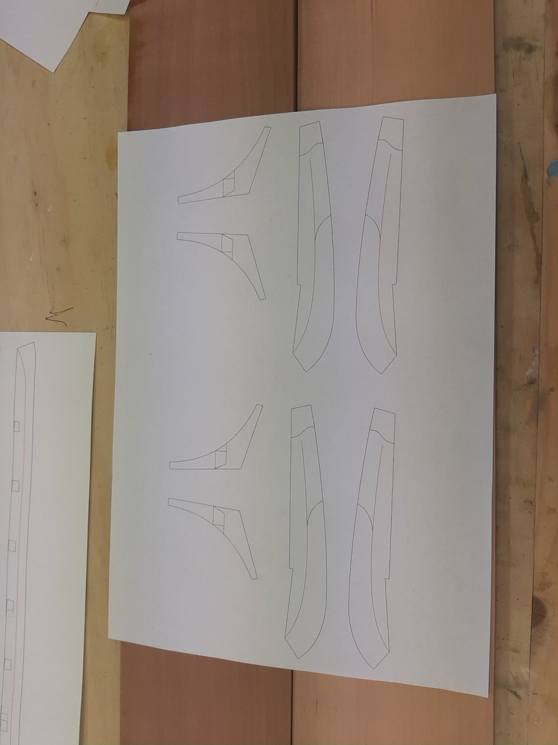
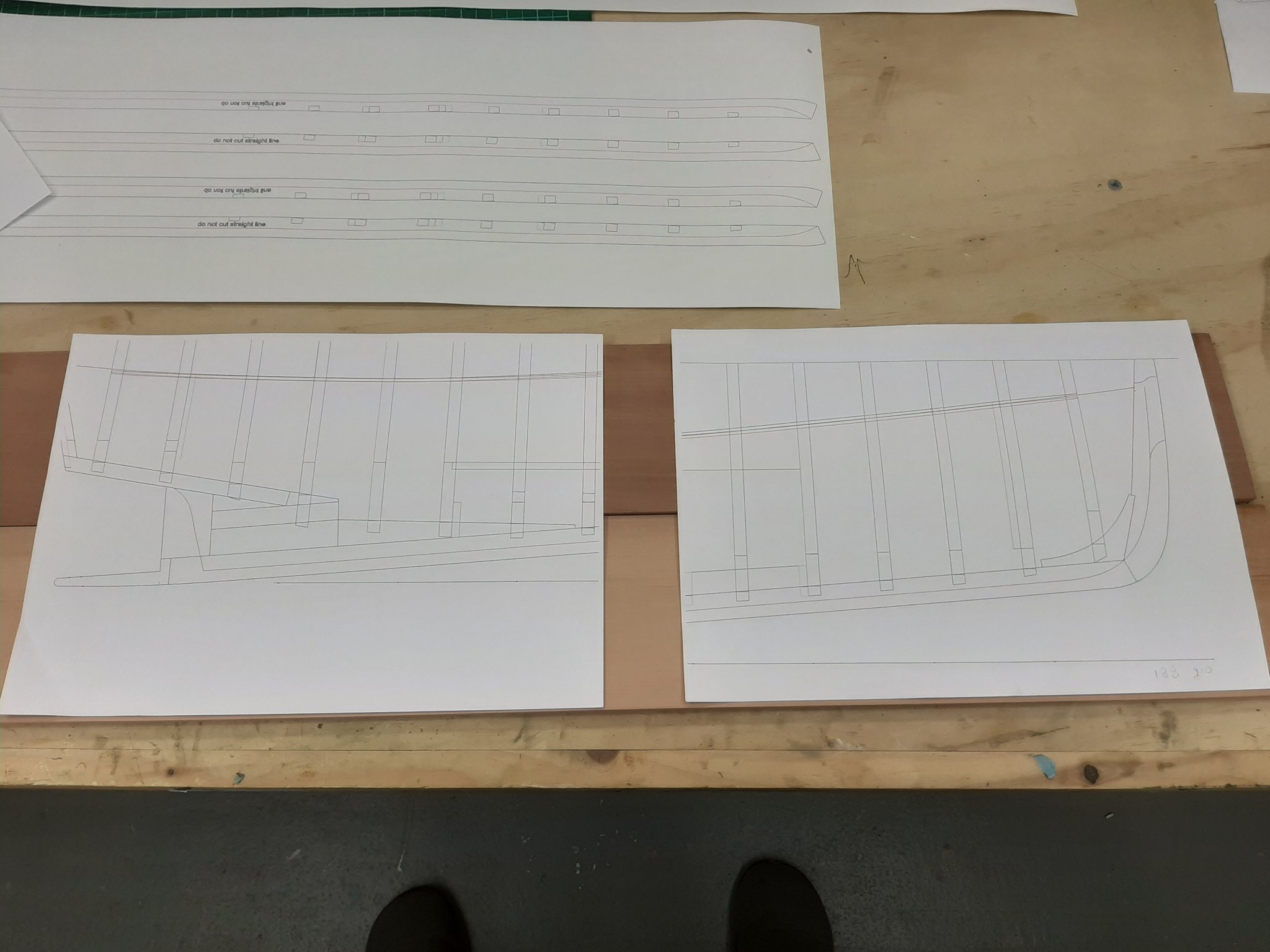
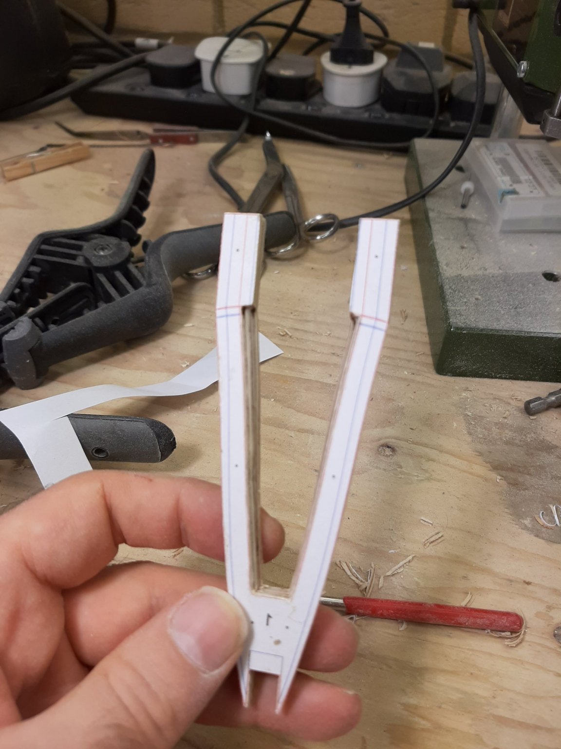
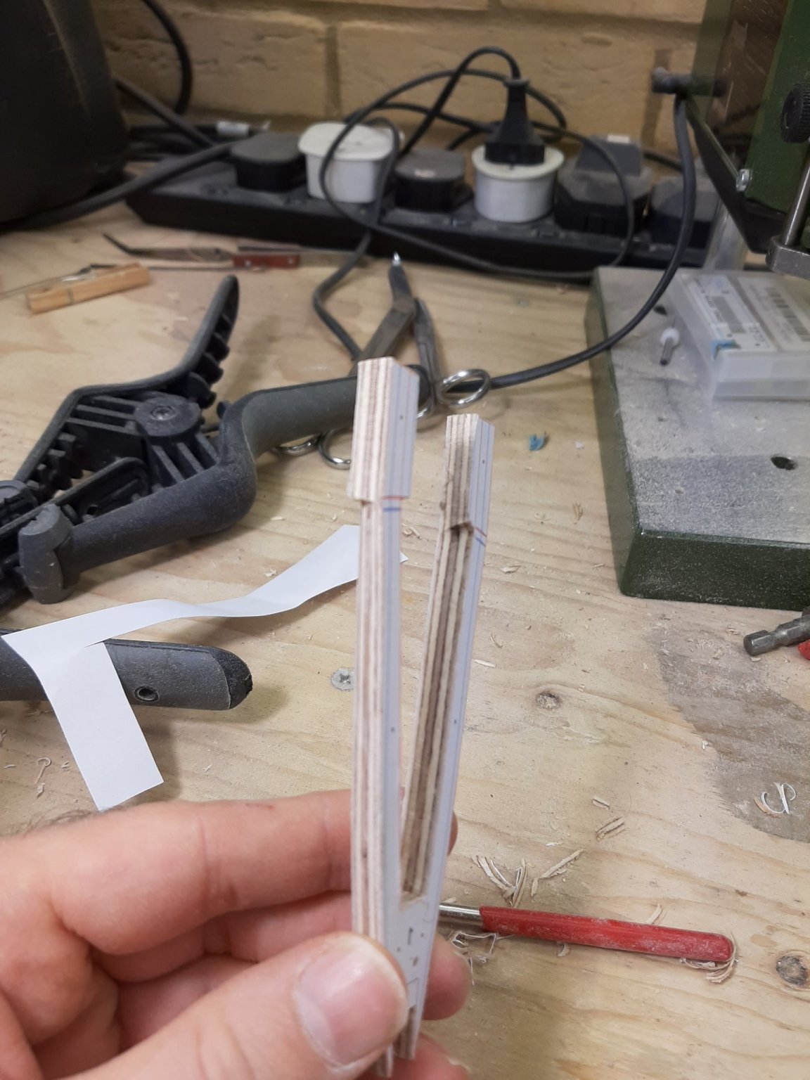
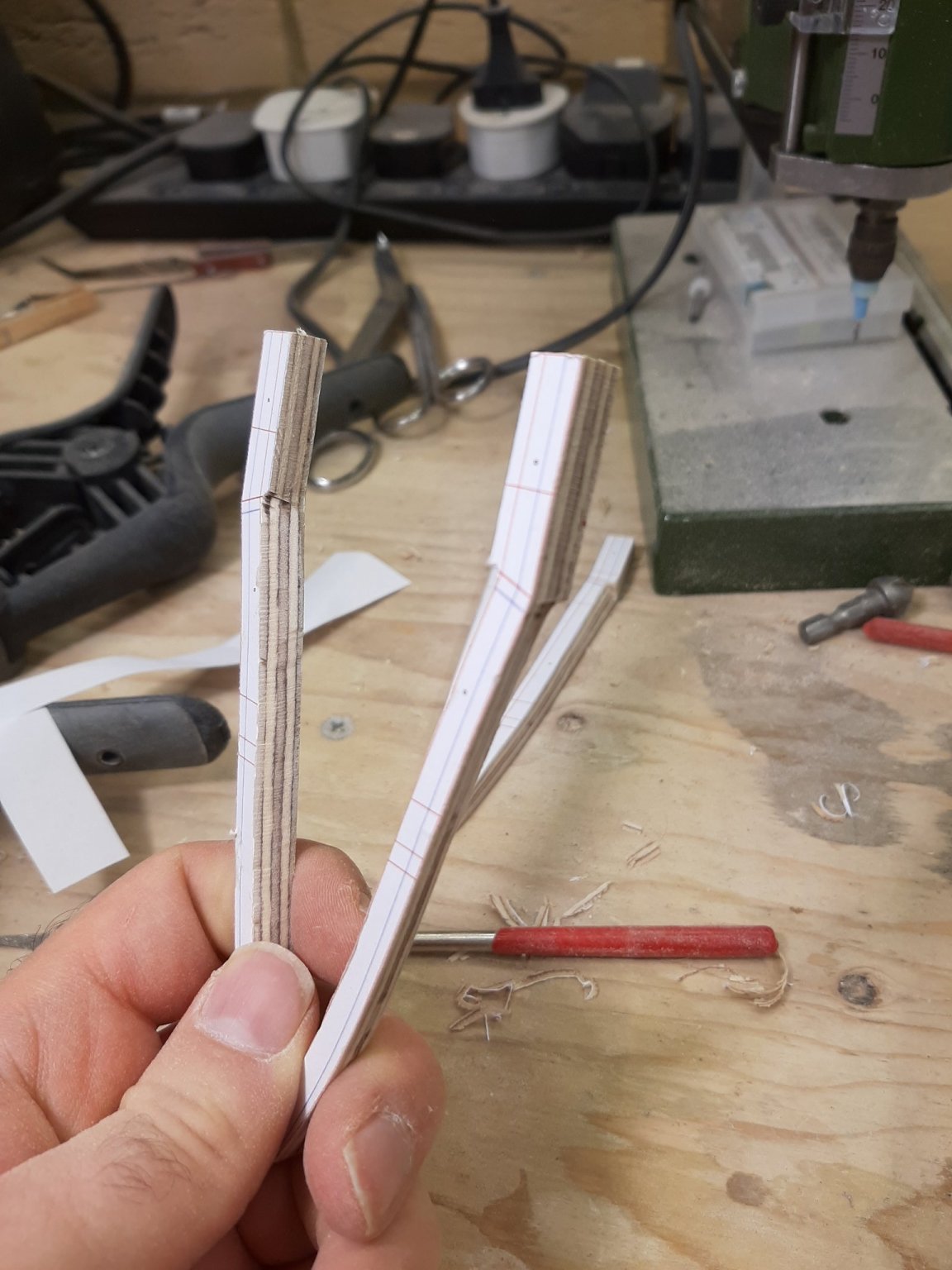
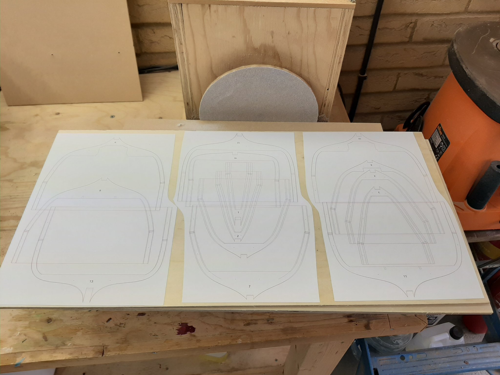
Bob many thanks, indeed this progress is pretty fast for my standards Keith and Allan, Fanta Zero Sugar is one of those little pleasures that make life meaningful! Now, I stole a few moments to spend in the shipyard. I tidied up a bit and then did a tiny bit of work. The frames are underway, so I wanted to start work on the keel, stem and deadwood/stern. These will be partly visible and furthermore the rabet will need to be curved, so they cannot be made from plywood. Even if I end up painting the boat (quite possible), they still need to be made from wood. I chose to use pear, mostly because I forgot I also had beech which is much cheaper. Now, I have 2 sheets of pear to choose from, a lighter shade and one with the usual darker pear wood colour. I chose to use the lighter one because it was dead straight and flat, whereas the darker one was slightly warped and cupped. Shame really, lovely wood The sheet is supposed to be 8mm but it is actually 8.5, no harm done though, I ll just sand the notches on the frames a bit more. Now, this is the keel and the top view of all the frames For the stern and dead view, I have the option of either building it up from pieces exactly as the plans show, or doing it en block, from the same 8 mm sheet. The first option is too complex and I am already cutting corners with this boat with the plywood frames. Makes sense to make it one piece These are the patterns for the stem and knee, again from 8 mm sheet This are the side views patterns for the bow and stern, will help to make sure all are in roughly the correct position I managed to cut the keel straight but then I was summoned in the house. It will probably be a while before I can do any more work Take care Vaddoc


-
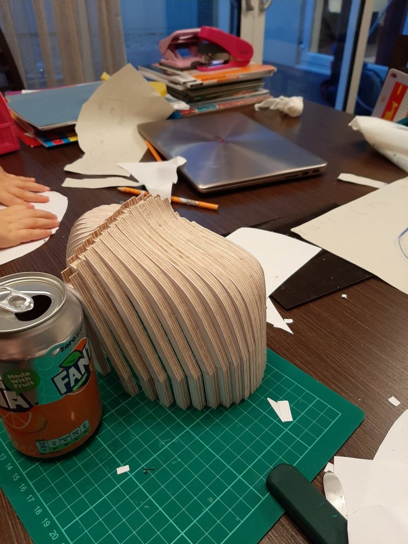
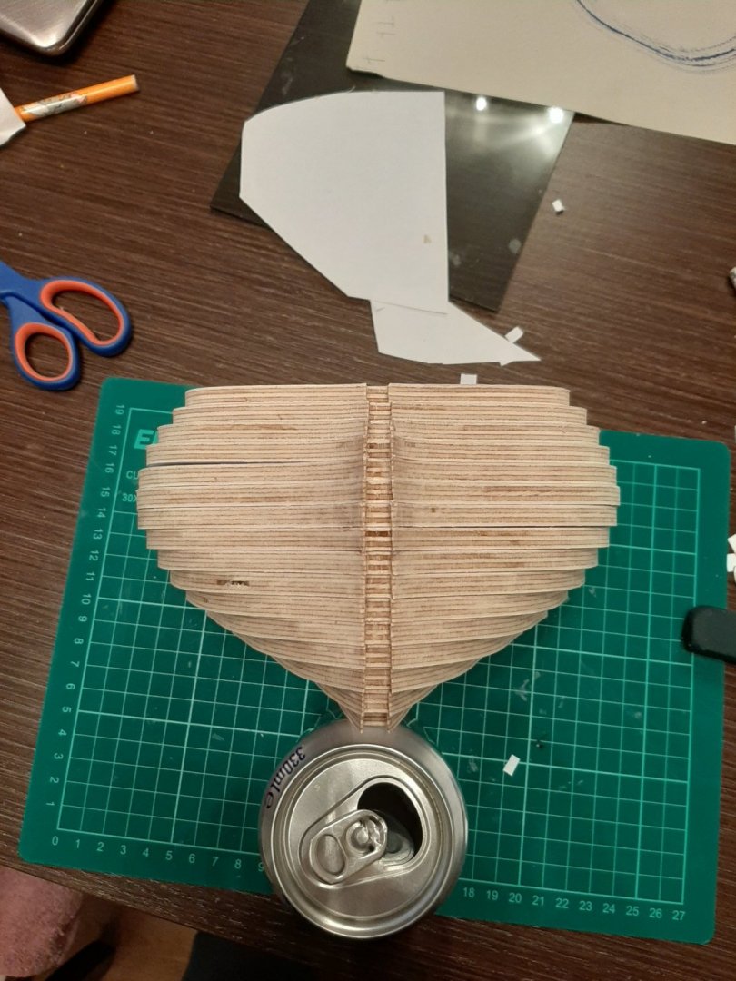
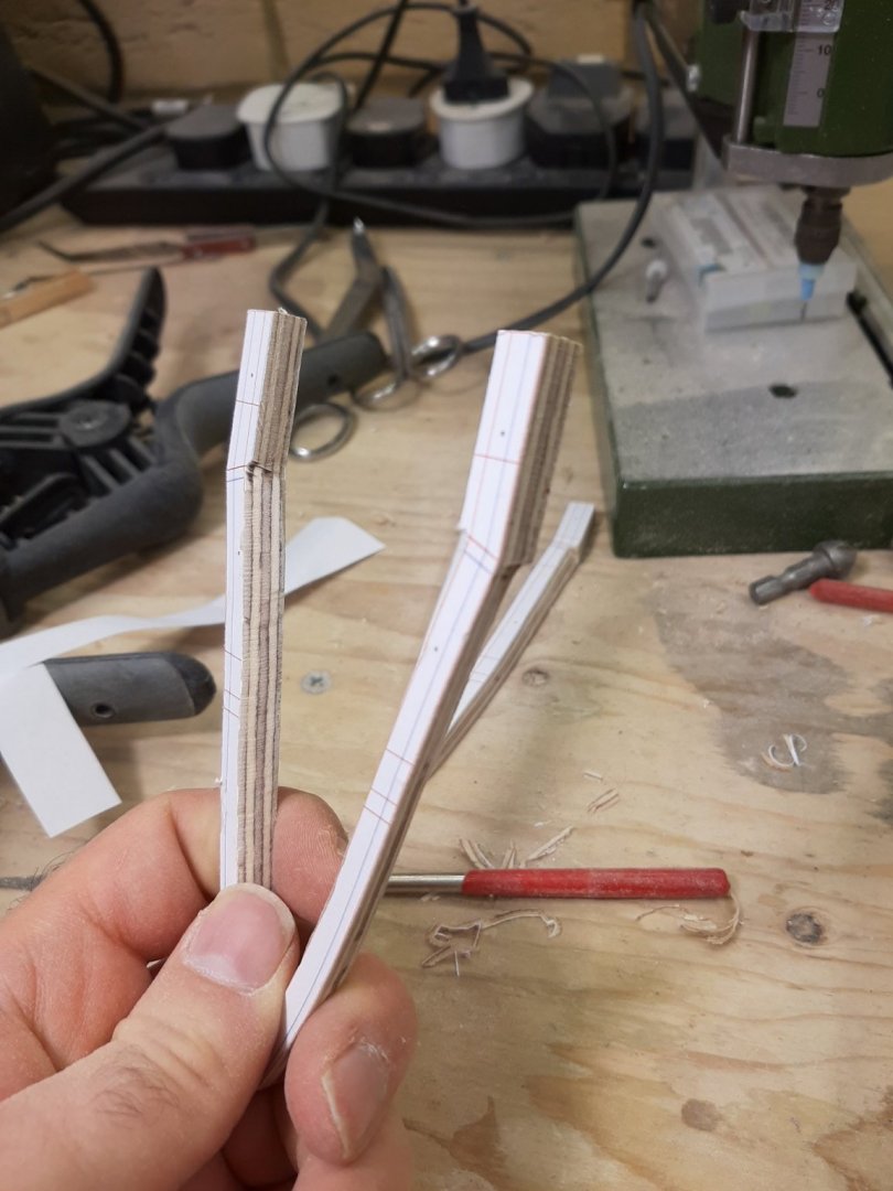
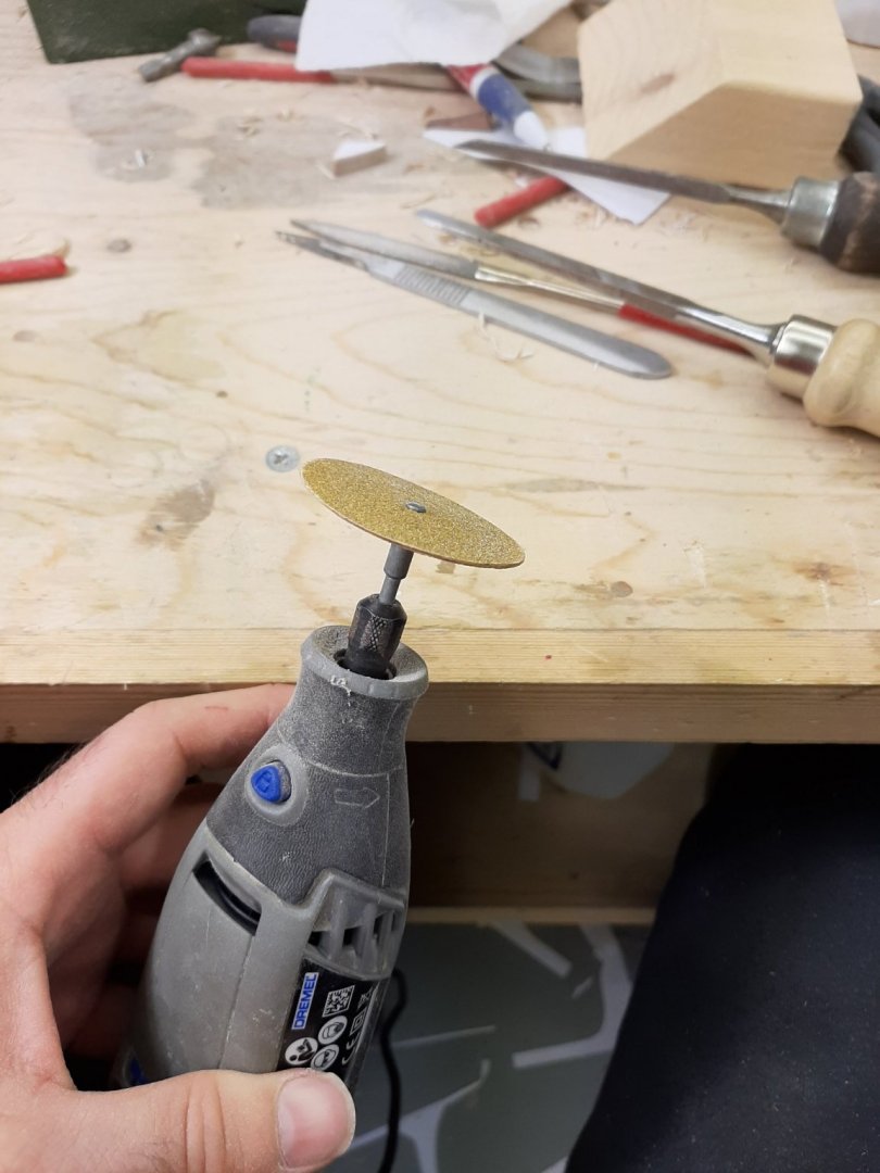
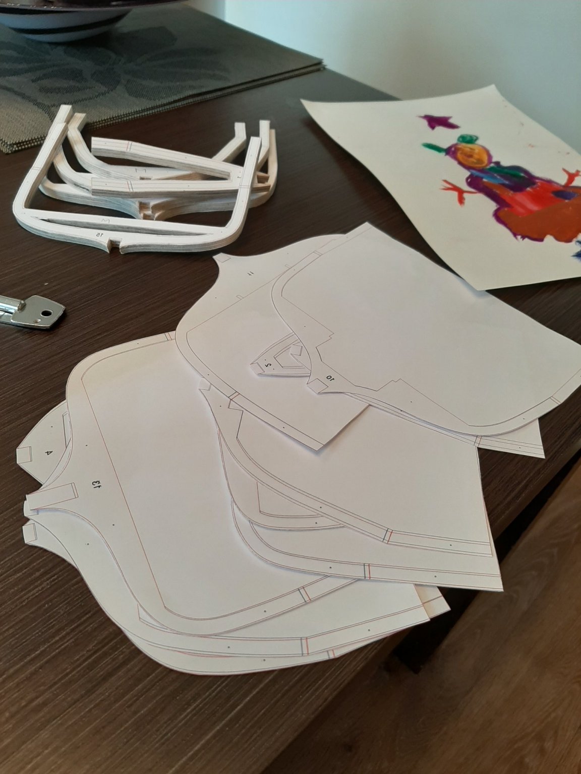
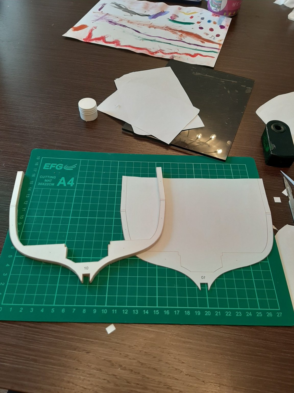
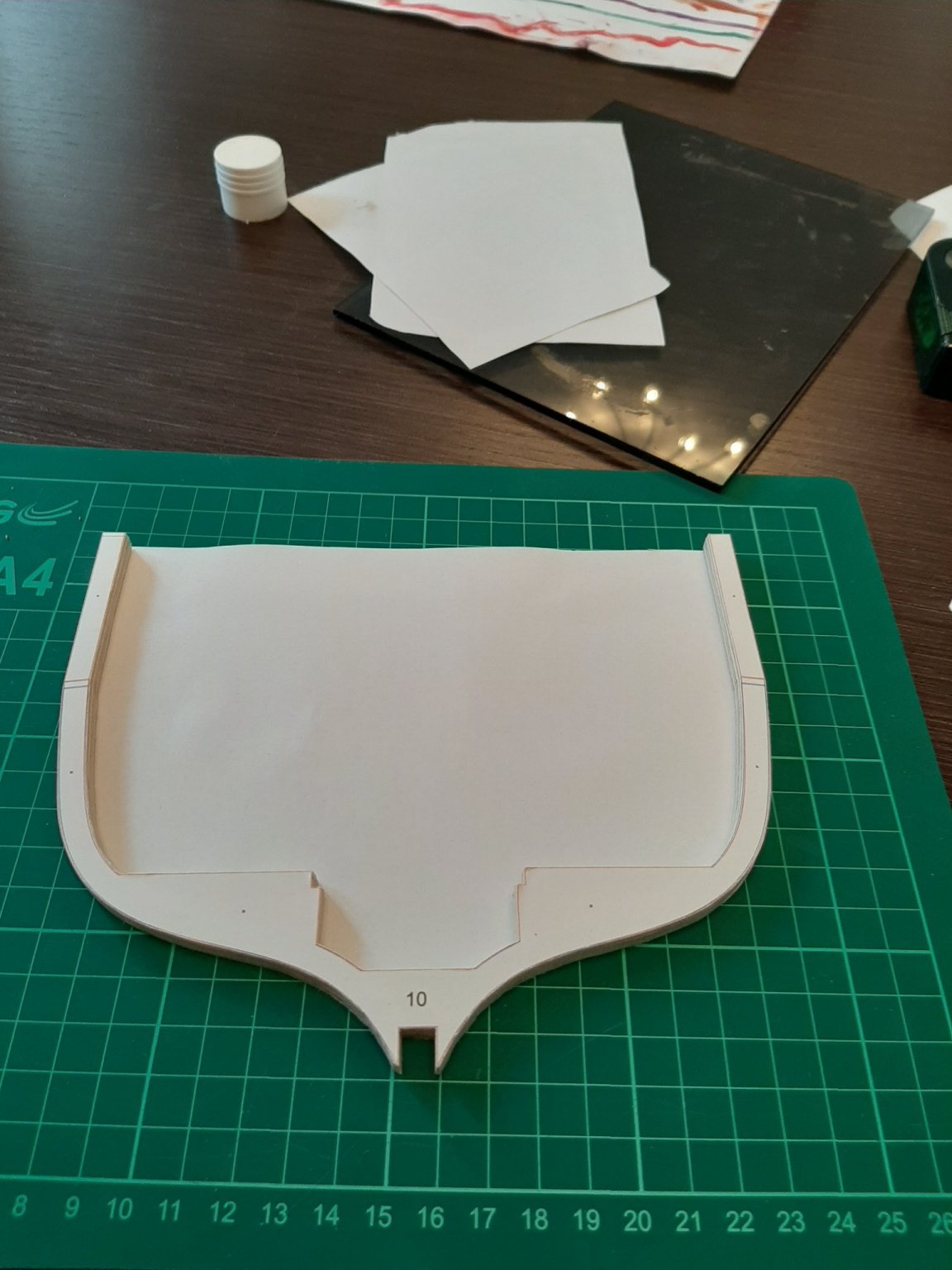
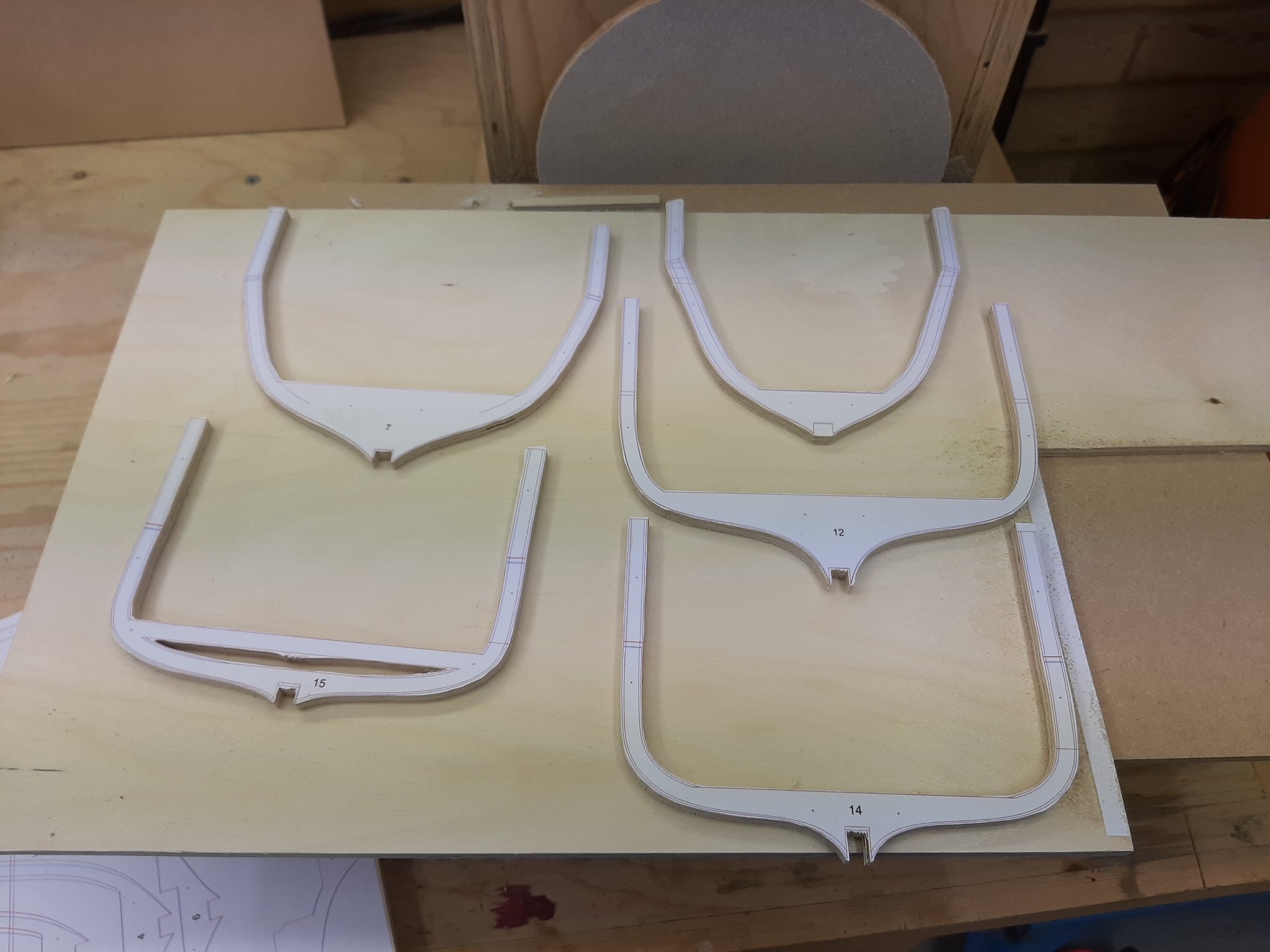
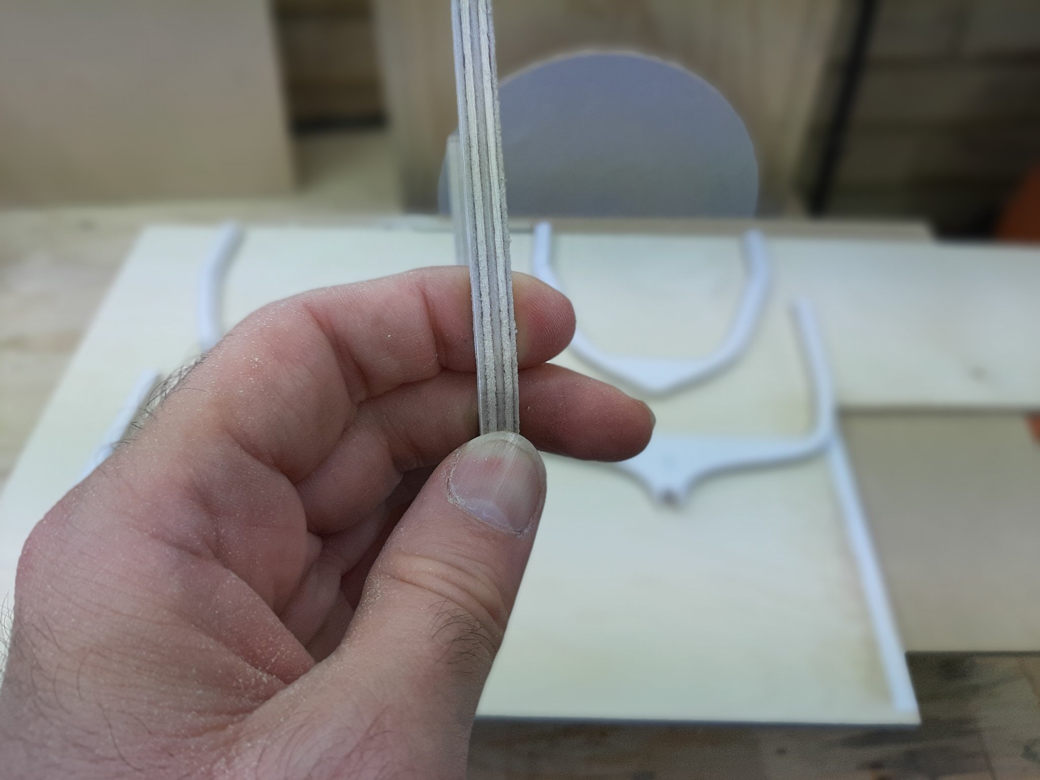
I think another update is in order. Box, many thanks but actually the frames on the photo were roughly cut , they were later finished to the exact pattern. Keith, it was actually very easy to glue the mirror pattern on the back. I am pretty sure there are already significant tolerances in the build, a bit more to the left or to the right will make no difference I think! I just managed to scrape a few moments here and there to work on the boat. I first finished all the frames to the exact pattern using the disc sander and mostly diamond files, which remove a lot of wood quickly. This took a while as the plywood at 6 mm is pretty thick. Then, I printed mirror patterns for all frames and with scissors cut the outline. Then I simply glued the frames to the back of the pattern. It actually worked pretty well. I could not resist aligning the frames, nice curves I must say... The straight parts that ruin the poetry will later be cut off, they are there just to help to set up the frames. However, this was the easier part. I now need to cut the bevels, both for the outer and the inner planking. This is pretty challenging. The diamond files are not useful here. The disc sander is far too aggressive and far too large. What actually made the task easier was to attach round sand paper to the Dremel. I like this trick, it sands not too aggressively but also is flexible and can fit in tight spaces. A mountain of work left, I ve only sanded the bevels for two frames. I also printed the patterns for the keel and stem. I think I will cut the deadwood en block instead of building it up. I am not 100% certain how the boat will be assembled, probably the right side up as the frames will be permanent so need to somehow be well attached to the keel. We ll see. Regards Vaddoc


-
Prime coating the hull
vaddoc replied to closehaul's topic in Painting, finishing and weathering products and techniques
Do not worry. The smoother the better. You will not regret the work you put in preparing the surface for paint. The primer magnifies faults 10 times, the paint a hundred. 0000 wool is something like 400-600 grit I would think. No issues, both acrylics and enamels will love your smooth primed surface. -
A bit over 2 ft Bob, around 70 cm. The longest plank should be 80 cm in length.
-
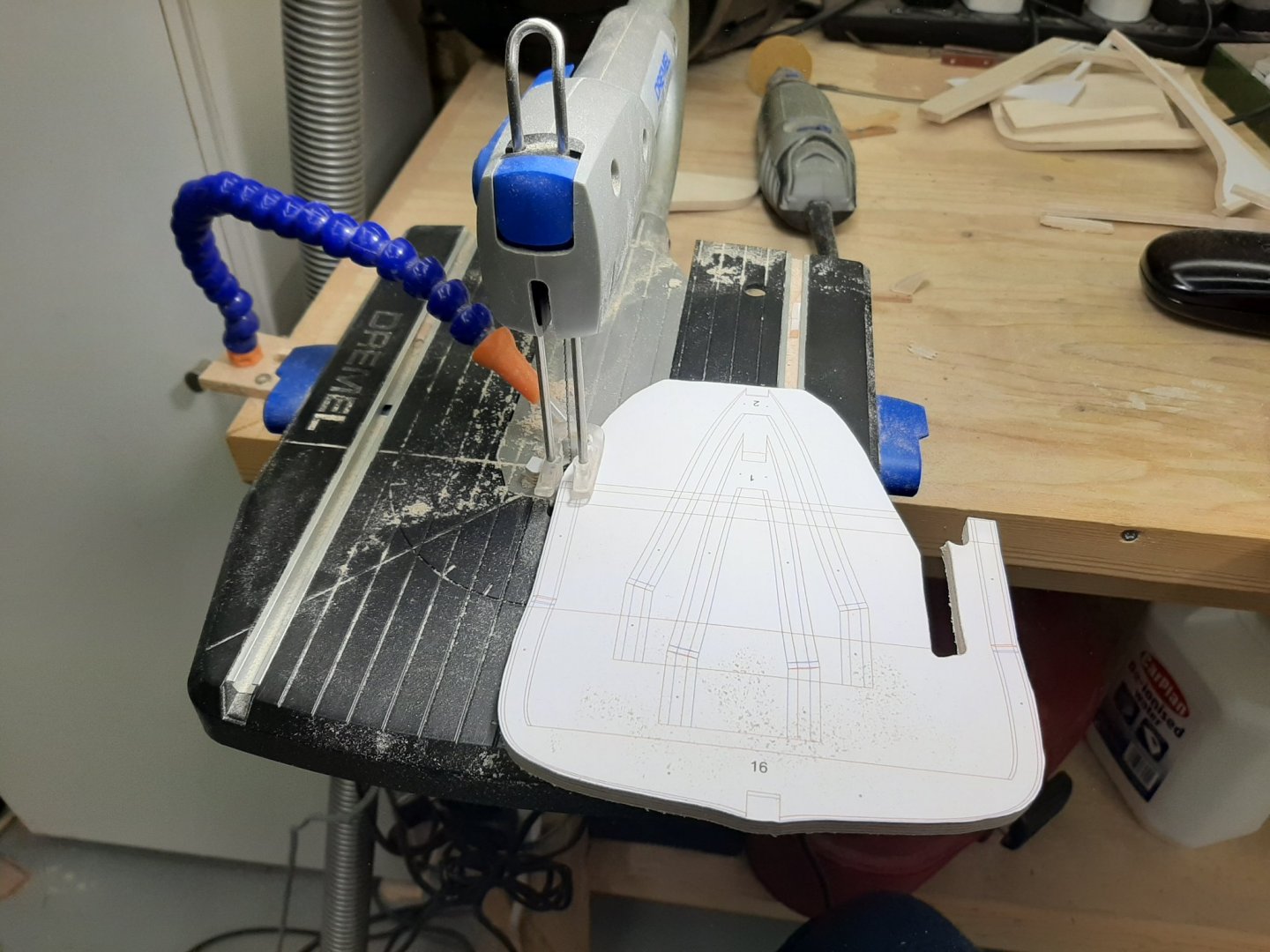
Now, I need to correct a couple of mistakes. The actual frame count is 16 as No 17 would be the transom. Furthermore, there only 14 frames in the above arrangement as somehow I missed two! In any case, the templates have been glued to the 6 mm plywood sheet. This is very thick plywood bought from Cornwall models, it is very good quality with no voids, it reminds me of marine plywood although the wood is soft birch. The little Dremel Motosaw is actually doing a pretty good job and is cutting the plywood with relative ease. The frames at 6 mm thick I think will be sturdy enough for the job. All frames will need to be finished to the exact lines. Then, somehow a mirror paper pattern will need to accurately be glued to the other side to allow for the inner bevel to be cut. There is a lot of cutting and finishing to be done though!


-
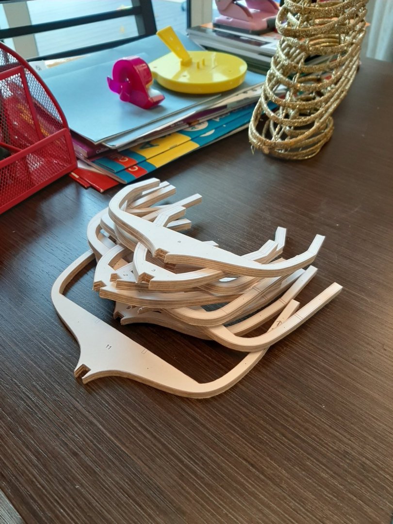
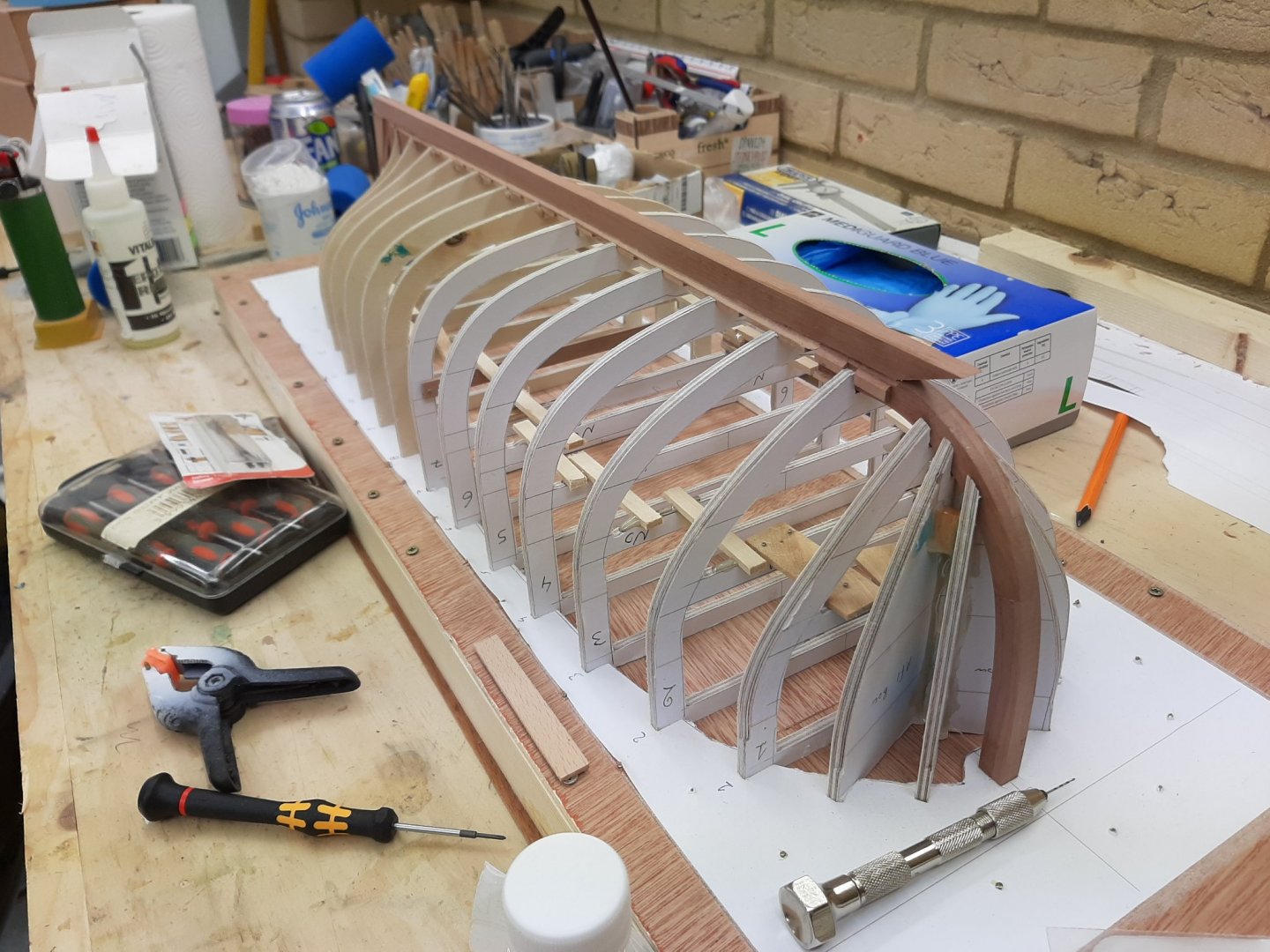
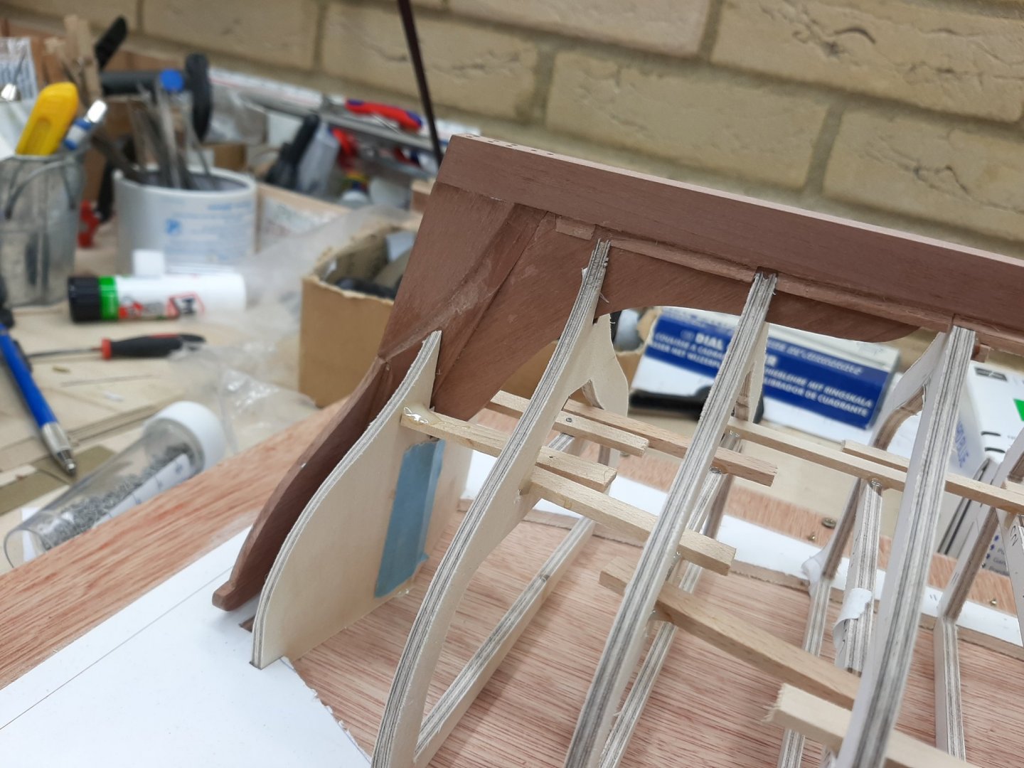
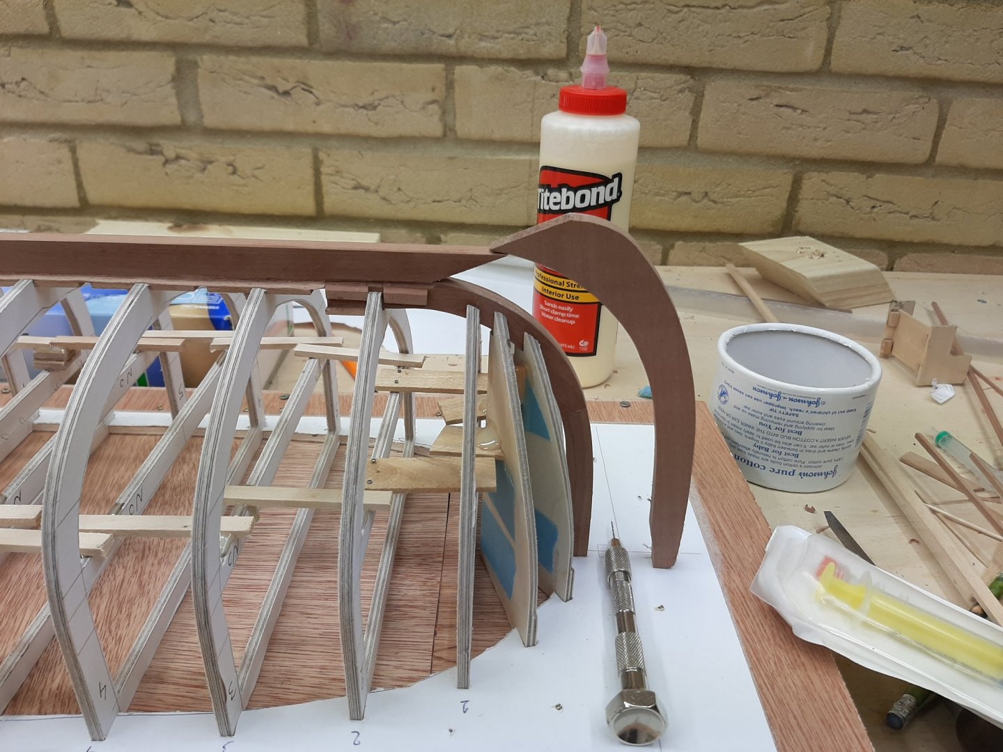
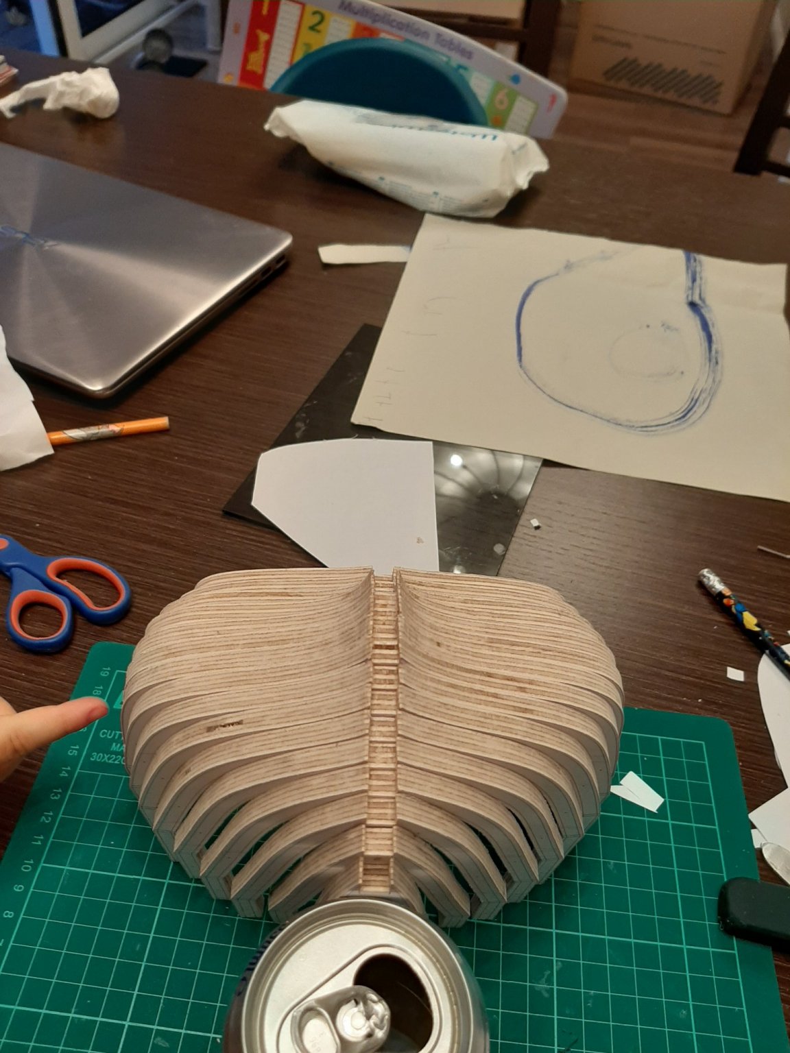
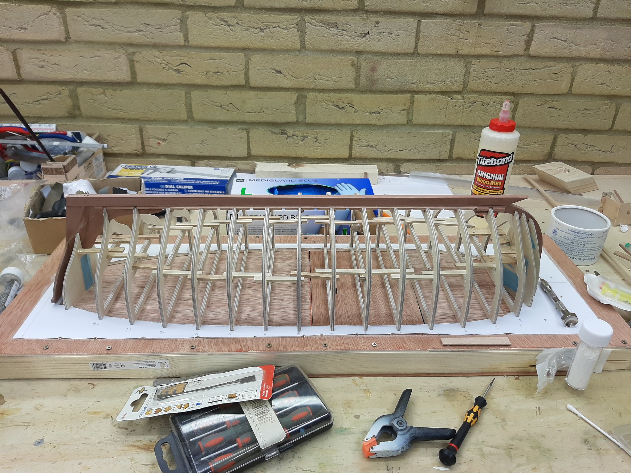
Dear all, many thanks for your comments and likes. Unfortunately It took me a while to come back to my log as life has gone into hyperdrive again. All the frames are now in place and strengthened with pieces of wood. The boat is ready to be planked! However, I will temporarily hold the build and concentrate bringing the Launch to the same point. I think it will be interesting, these two boats are completely different in shape and I am curious how the planking arrangement will compare. A few final photos, the log will continue with the (clinker) planking, provided I will manage to get the 2 mm beech planks to bend.


-
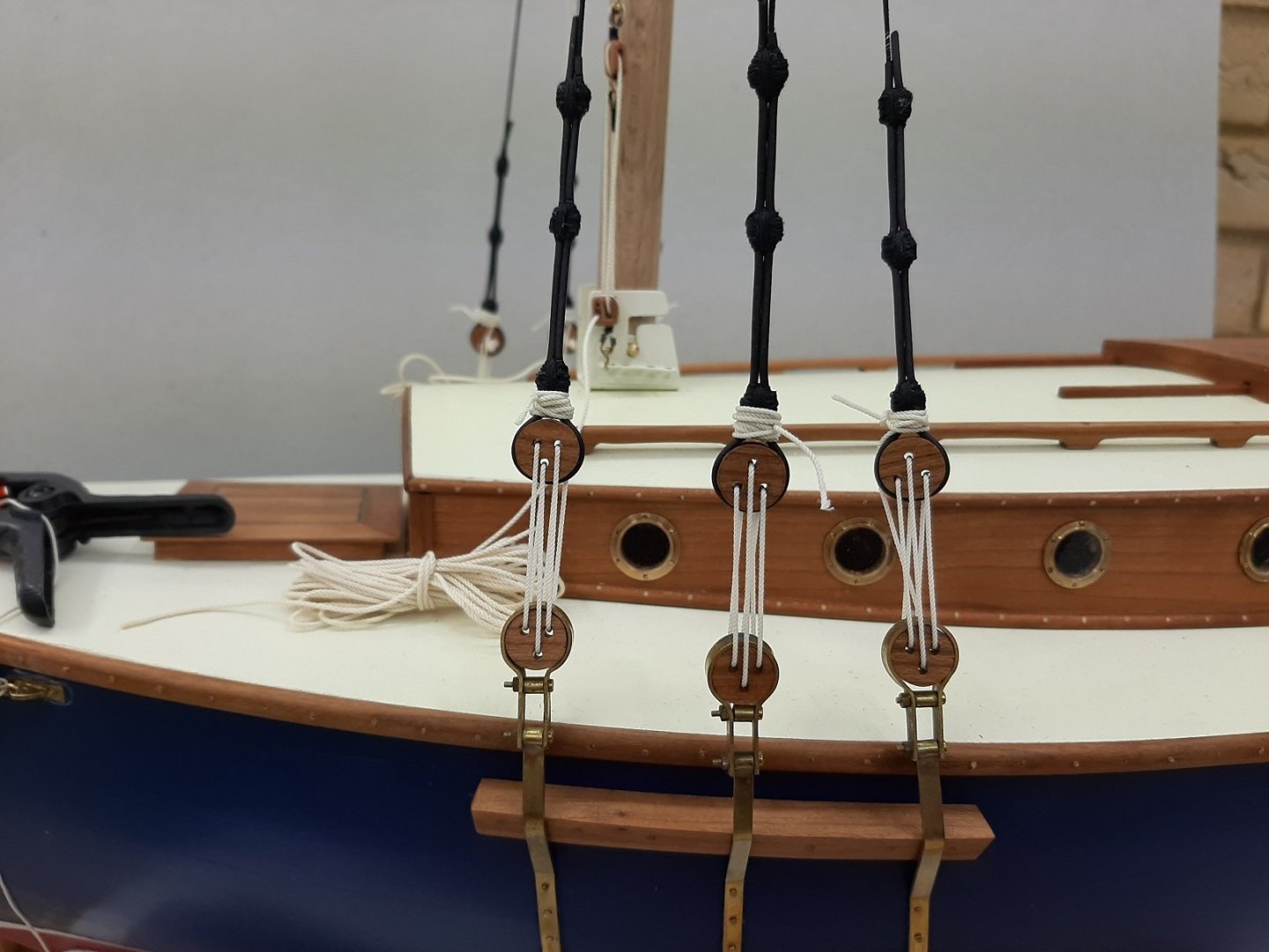
Brian, you wheel came out fantastic! Very impressive and precise work. Your log is a joy to follow
-
You know how it goes Bob. Good times follow bad times until things go bad again. We just need to enjoy the good breaks and soldier on during the bad ones. Soon you ll be back on your boat, scratching your head trying to figure out the rigging. Stay safe Vaddoc
-
Beech is cheap Bob, I think around £4-5 per sheet 1000 x 100 mm. Pear, cherry and the other premium woods are much more expensive. If you visit both sites you can check the prices. Yes, it is a wood I very much like. It bends nicely and I like how it combines with pear. Now, for the Deben I used maple which is a fantastic wood for planking. I did not appreciate however that beech, although it bends as nicely, is also much harder. I foresee troubles ahead!
-
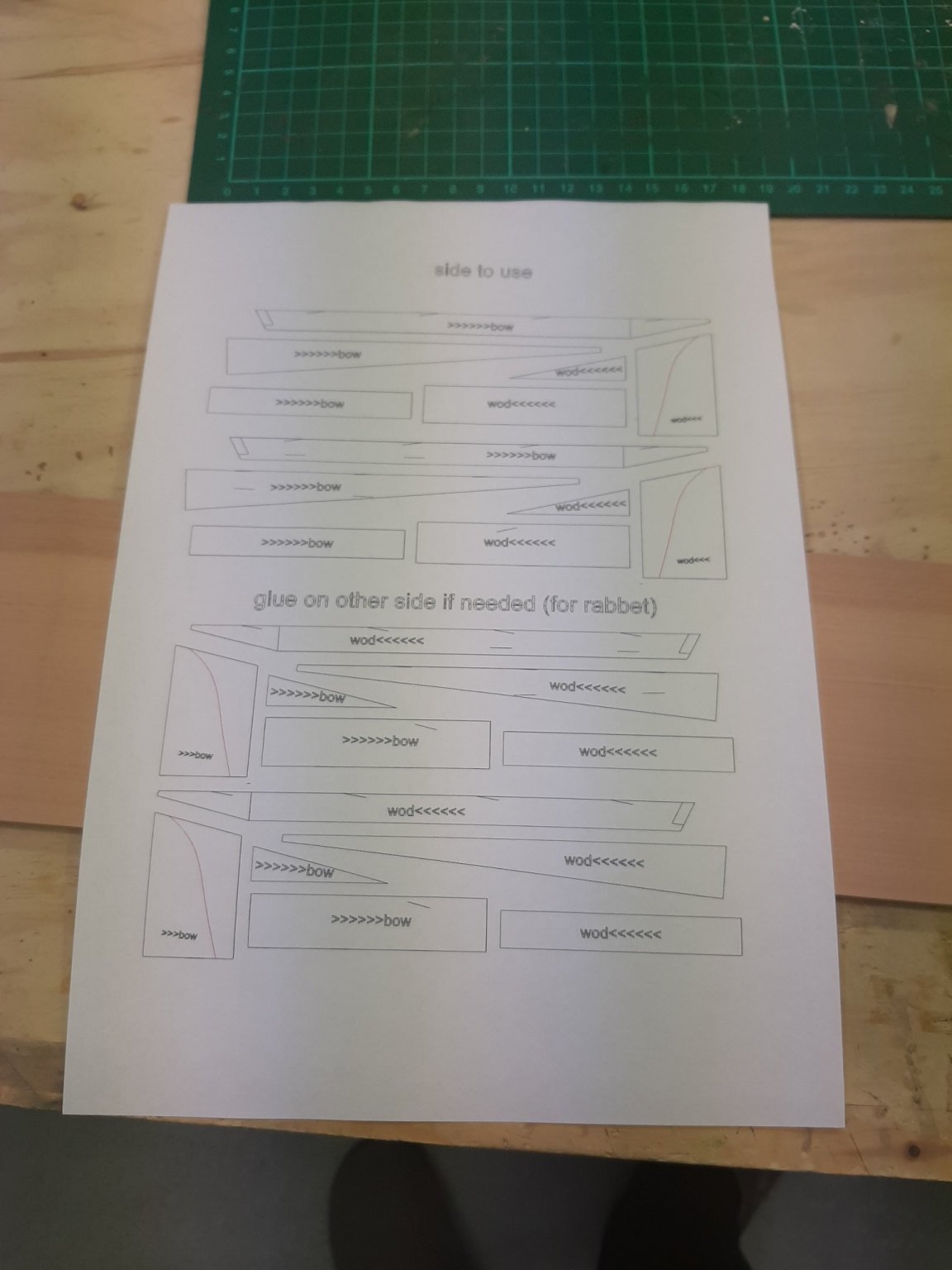
Welcome aboard Bob and Patrick! I am really sorry it has taken me so long to post a reply-life has gone into hyperdrive. Still, I managed to do a bit of work on the boat!The Yawl is ready for planking, so time to bring the launch to the same level. First, I ordered some more wood, this time not from Oliver at Arcowood but from Massive Holz. Once again I find that the former provider indeed selects the timber that is sent out. The latter does not seem to do this as much. I received some sheets that have defects and colour variation which I think should not have been sent out, considering we pay £10 or so for a little plank. (I edited this part to be fair as most of the sheets were fine) Then, I finished the whole boat on CAD, based on plywood frames 4 mm thick. The reason being I have 2 large sheets of 4 mm plywood I had laminated myself for the Yawl. These frames will be completely hidden so no need to sweat making them from expensive pear or cherry. However, after I had finished, I cut half a frame and realised that my plywood was delaminating but also that 4 mm would not be thick enough to withstand the pressure during planking. I will use beech which might bend nicely but at 2 mm, is also a very strong wood. So, back to the drawing board. I ordered some plywood 6.5 mm thick from Cornwall models and changed the frames to 6.5 mm. This took a decent amount of work! So, here is where we are now There will be 17 frames, initially very long to form the building jig, then cut to length. This is how to fit 17 frames in a 600 x 300 mm sheet! It is great fun building this boat, it builds like a clipper with its rabet, horn timber, dead wood and all but it is such a tiny boat! It will even have a bit of deck... Next update hopefully will have a bit of saw dust. Take care Vaddoc
.thumb.png.fc43df36b0ad740099f311c53ad7fbf3.png)

-
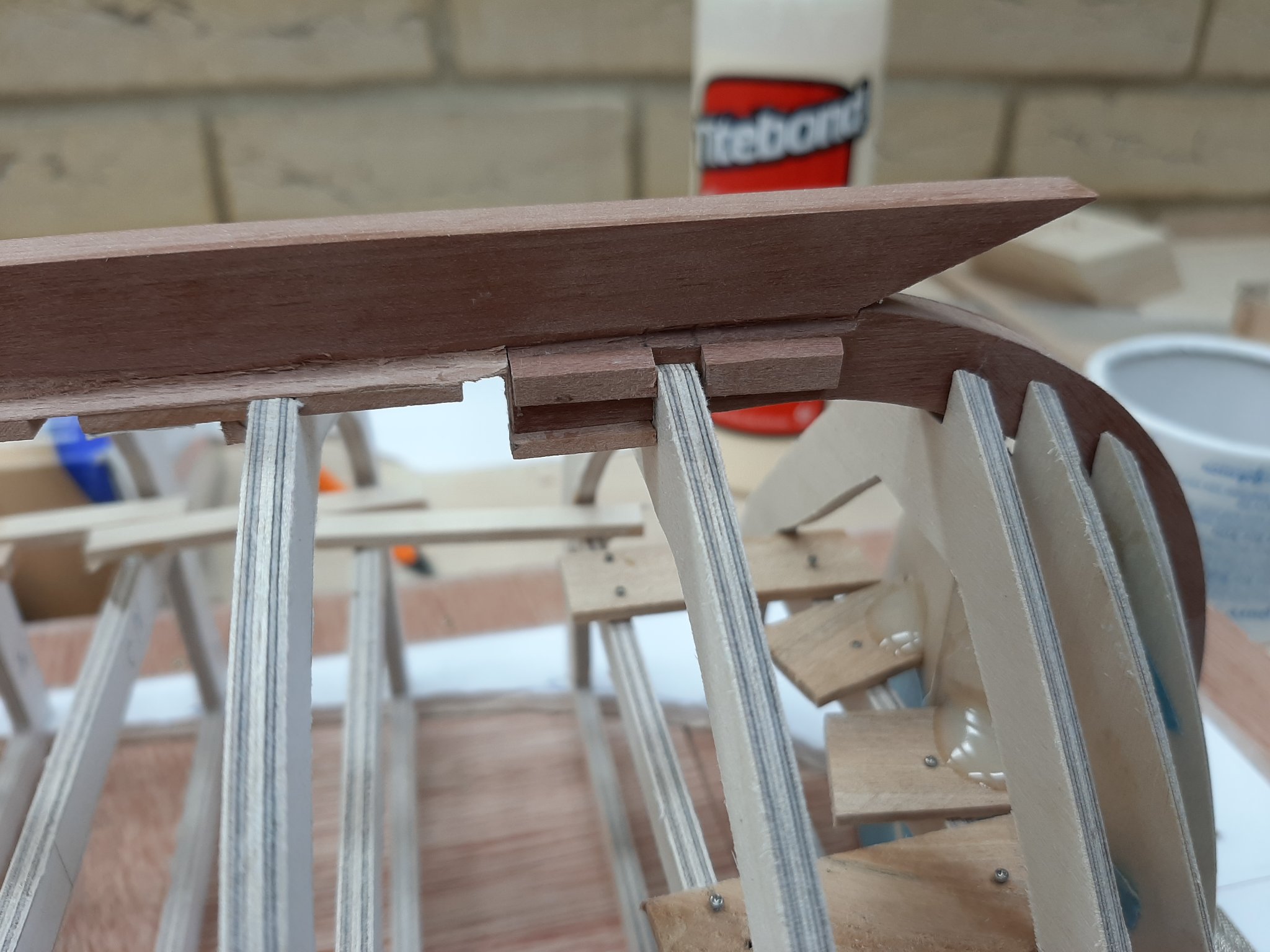
Take a small piece of plank material, rest it on the frame, slide it down on to the rabet line, cut the bevel so the plank thickness is all in the rabet groove, with the plank piece resting on wood in both surfaces. Do the same for all frames (the angle will constantly change). Connect all the rabet segments you ve cut eyeballing things and/or using pieced of plank material. Rabet done
-
It might be easier to paint the hull upside down or something may go horribly wrong and the whole thing needing to sand down and re-do. If you paint the hull, it will need sanding and sealing anyway so that means treating it rough. I would finish with the hull and then proceed. For the rest of the build, rest the hull on something that will not scratch it.


.png.08a6a2eb18d06dcfd25d217292f95f69.png)