.jpg.f26acc9a74319261612561bfa7da1303.jpg)
vaddoc
-
Posts
1,605 -
Joined
-
Last visited
Content Type
Profiles
Forums
Gallery
Events
Everything posted by vaddoc
-
.thumb.jpg.6fd4c1b78768bb3efd745ab810936005.jpg) Beech is cheap Bob, I think around £4-5 per sheet 1000 x 100 mm. Pear, cherry and the other premium woods are much more expensive. If you visit both sites you can check the prices. Yes, it is a wood I very much like. It bends nicely and I like how it combines with pear. Now, for the Deben I used maple which is a fantastic wood for planking. I did not appreciate however that beech, although it bends as nicely, is also much harder. I foresee troubles ahead!
Beech is cheap Bob, I think around £4-5 per sheet 1000 x 100 mm. Pear, cherry and the other premium woods are much more expensive. If you visit both sites you can check the prices. Yes, it is a wood I very much like. It bends nicely and I like how it combines with pear. Now, for the Deben I used maple which is a fantastic wood for planking. I did not appreciate however that beech, although it bends as nicely, is also much harder. I foresee troubles ahead! -
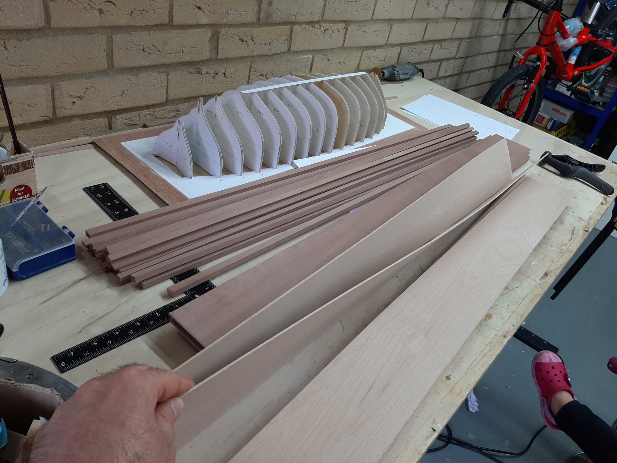
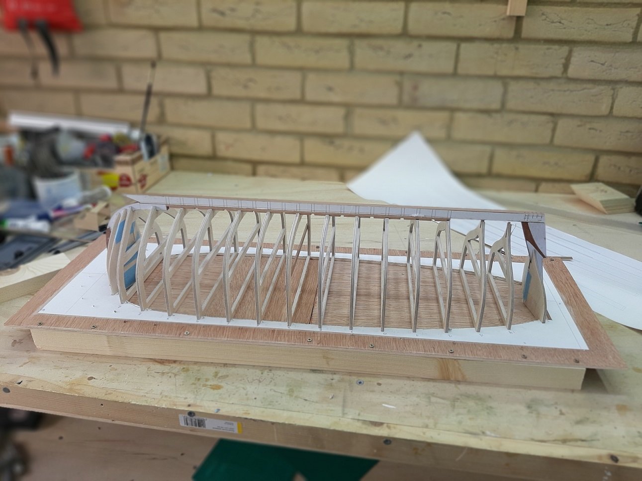
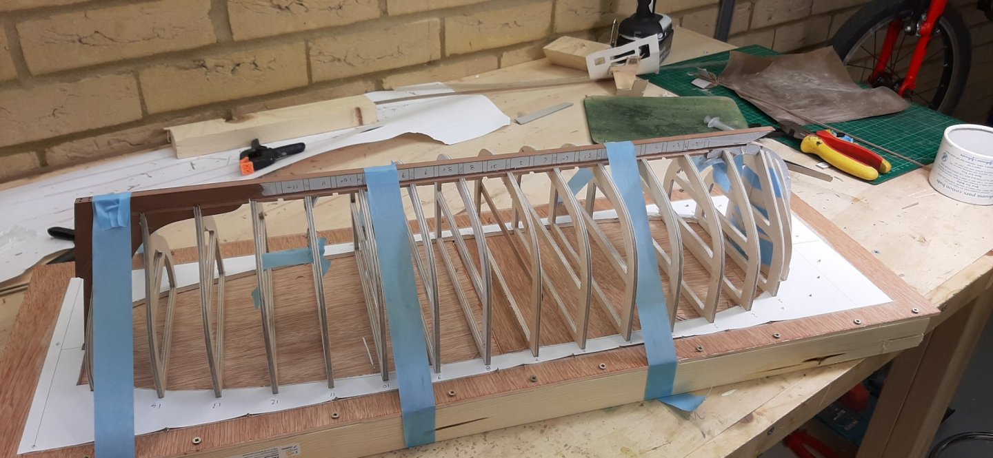
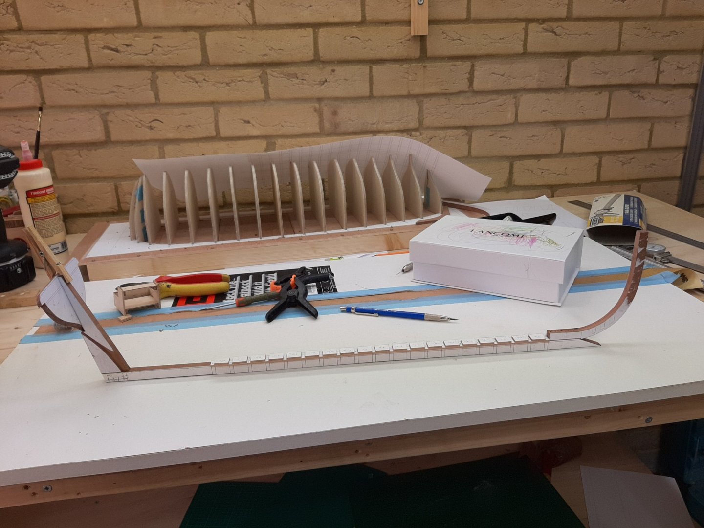
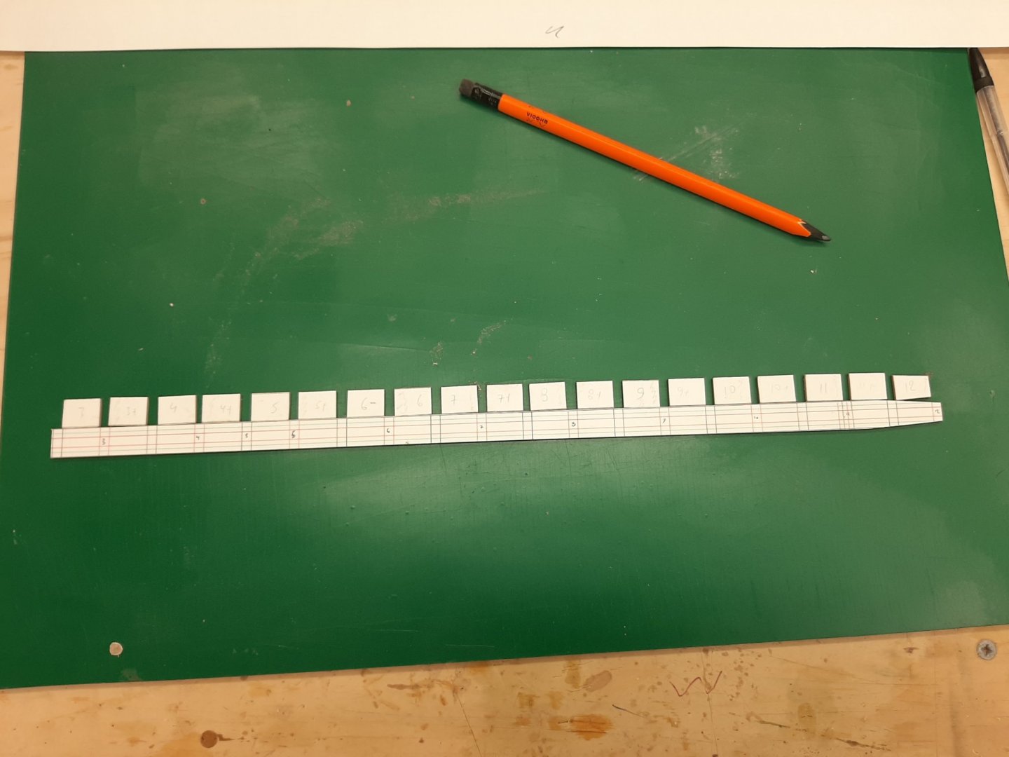
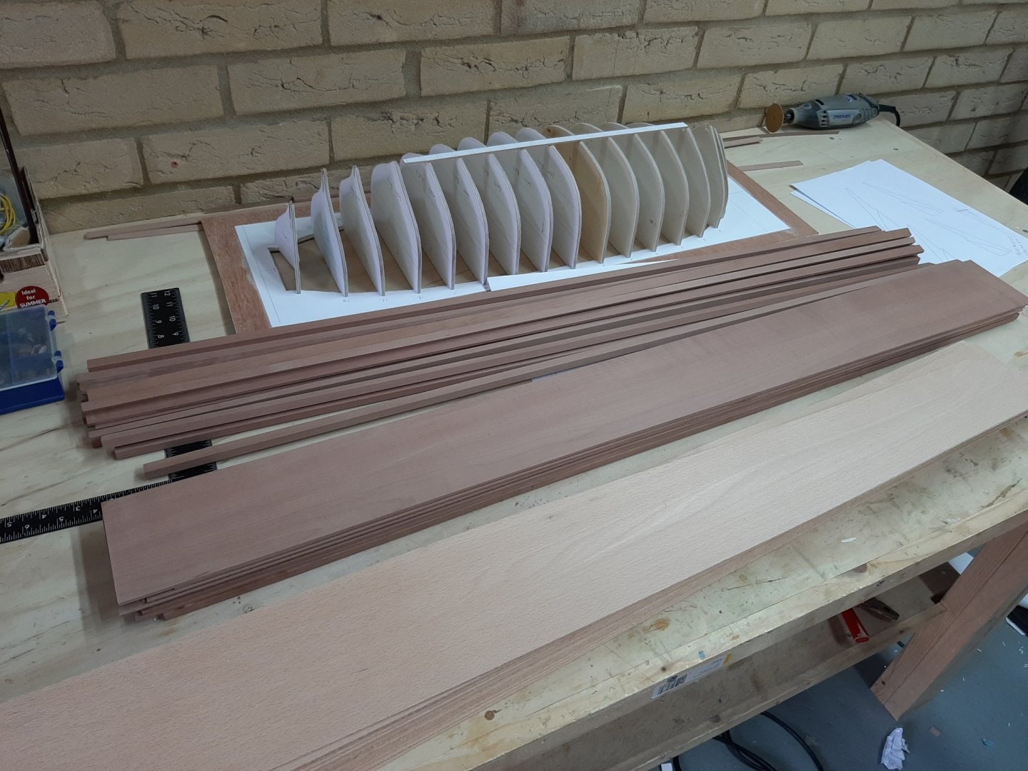
Welcome aboard Bob and Patrick! I am really sorry it has taken me so long to post a reply-life has gone into hyperdrive. Still, I managed to do a bit of work on the boat!The Yawl is ready for planking, so time to bring the launch to the same level. First, I ordered some more wood, this time not from Oliver at Arcowood but from Massive Holz. Once again I find that the former provider indeed selects the timber that is sent out. The latter does not seem to do this as much. I received some sheets that have defects and colour variation which I think should not have been sent out, considering we pay £10 or so for a little plank. (I edited this part to be fair as most of the sheets were fine) Then, I finished the whole boat on CAD, based on plywood frames 4 mm thick. The reason being I have 2 large sheets of 4 mm plywood I had laminated myself for the Yawl. These frames will be completely hidden so no need to sweat making them from expensive pear or cherry. However, after I had finished, I cut half a frame and realised that my plywood was delaminating but also that 4 mm would not be thick enough to withstand the pressure during planking. I will use beech which might bend nicely but at 2 mm, is also a very strong wood. So, back to the drawing board. I ordered some plywood 6.5 mm thick from Cornwall models and changed the frames to 6.5 mm. This took a decent amount of work! So, here is where we are now There will be 17 frames, initially very long to form the building jig, then cut to length. This is how to fit 17 frames in a 600 x 300 mm sheet! It is great fun building this boat, it builds like a clipper with its rabet, horn timber, dead wood and all but it is such a tiny boat! It will even have a bit of deck... Next update hopefully will have a bit of saw dust. Take care Vaddoc
.thumb.png.fc43df36b0ad740099f311c53ad7fbf3.png)

-
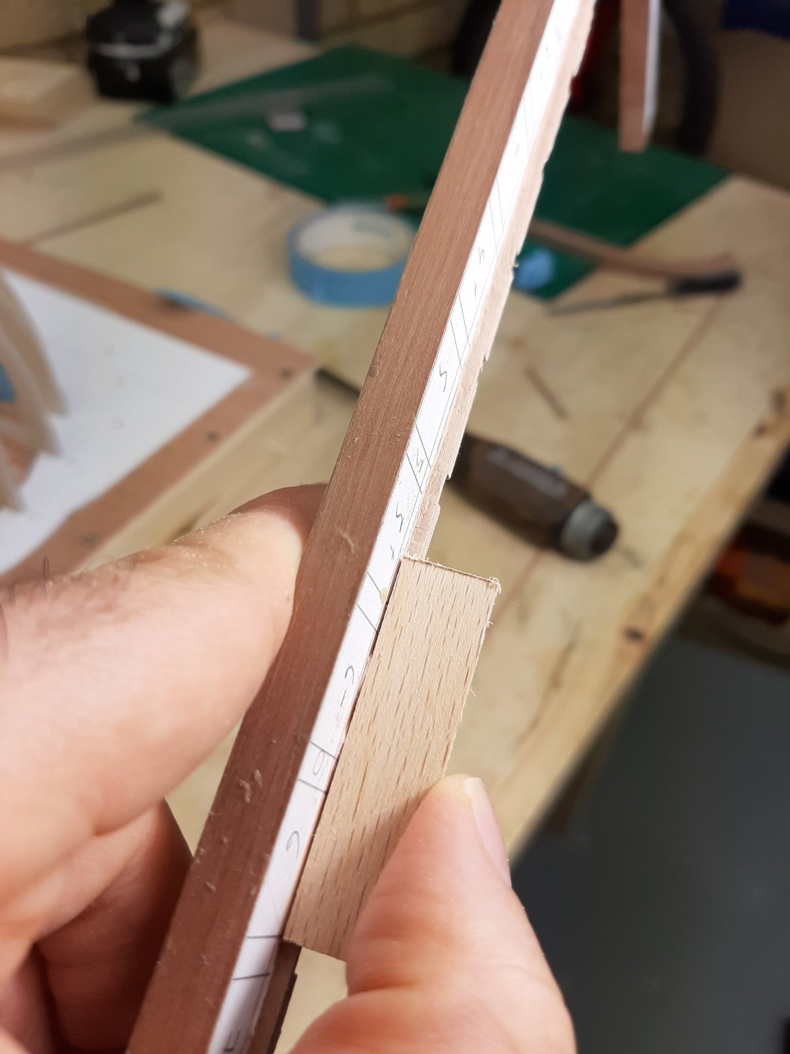
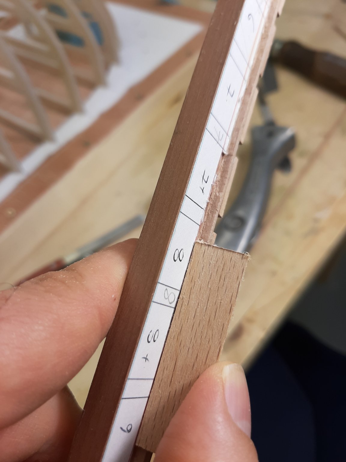
Take a small piece of plank material, rest it on the frame, slide it down on to the rabet line, cut the bevel so the plank thickness is all in the rabet groove, with the plank piece resting on wood in both surfaces. Do the same for all frames (the angle will constantly change). Connect all the rabet segments you ve cut eyeballing things and/or using pieced of plank material. Rabet done
-
It might be easier to paint the hull upside down or something may go horribly wrong and the whole thing needing to sand down and re-do. If you paint the hull, it will need sanding and sealing anyway so that means treating it rough. I would finish with the hull and then proceed. For the rest of the build, rest the hull on something that will not scratch it.
-
Vlad, I ve only just managed to catch up with your progress, you are doing a fantastic job, both your deck and your boats came out great. Some of your photos are truly amazing. You are clearly having too much fun!
- 200 replies
-
- 1
-

-
- cutty sark
- clipper
- (and 1 more)
-
Brian, this looks lovely, looking forward for the rest of the journey. Enjoy your vacation!
-
Replace the wood with something better?
-
Now this is a proper job! Very nice. Looking how long, wide and flat this boat is and how shallow draft it has and with all this armor on top, I can't help thinking that it would twist very easily. The pumps would probably work round the clock to manage leaks.
-
Nice work Keith. Quick question, these smoothbore guns, were they still firing round balls?
-
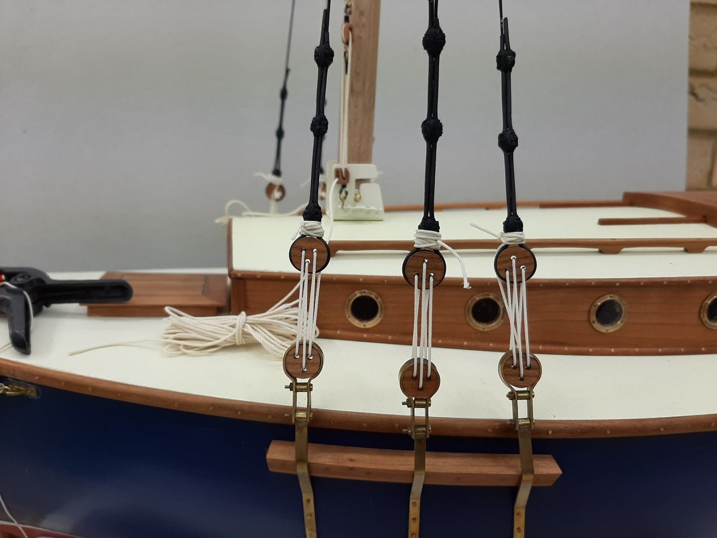
3 jibs/staysails, one with a boom, 2 sets of backstays, top sail on a yard and a gaff sail with reef lines etc - simples. Hats off to you Spyglass! 😄
-
Very nice Dick. I only just realised it has a flat bottom. This is a bit unexpected, the Mediterranean sea and especially the Aegean sea can be difficult, I did not know they were using this design back then.
-
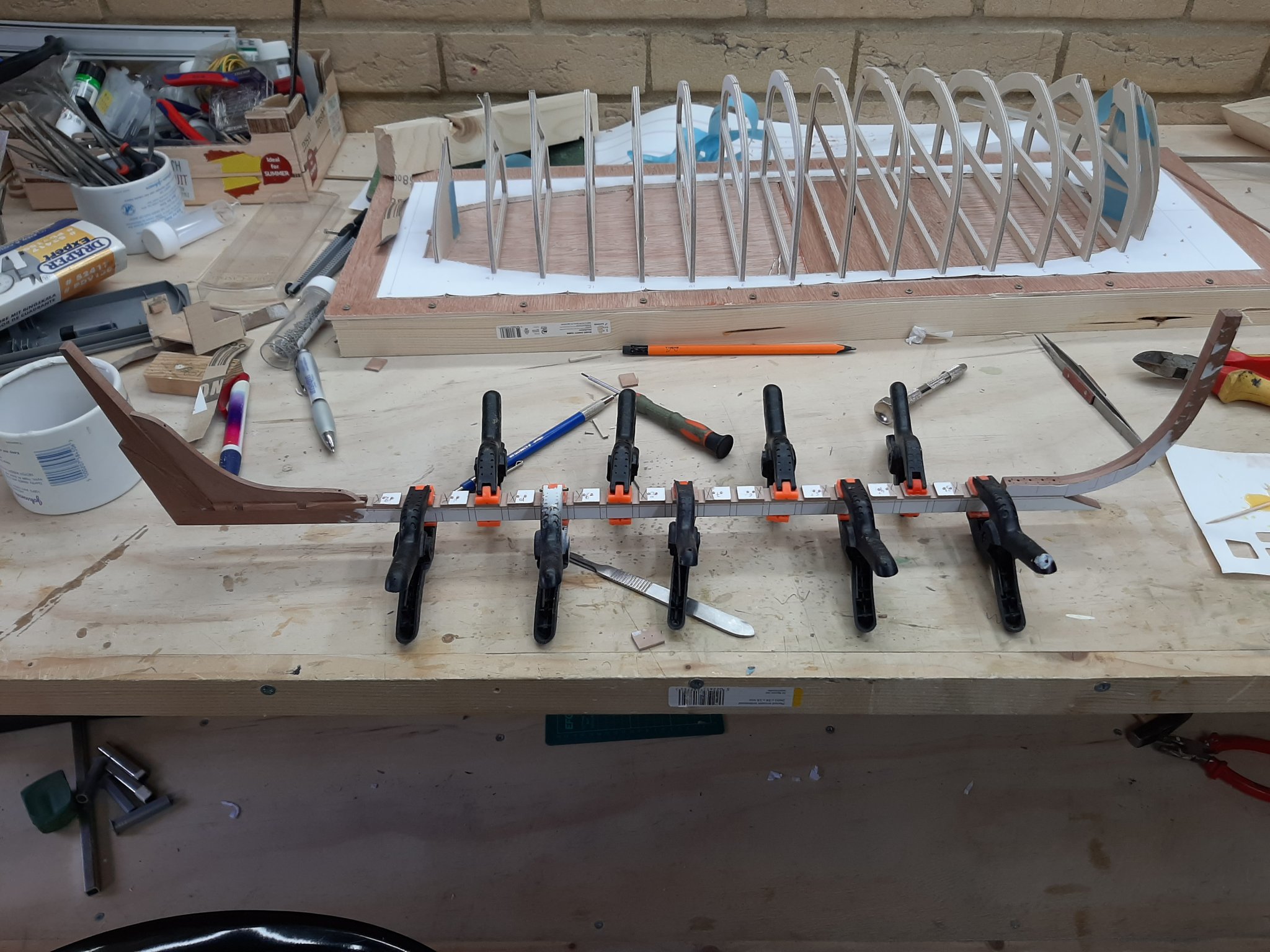
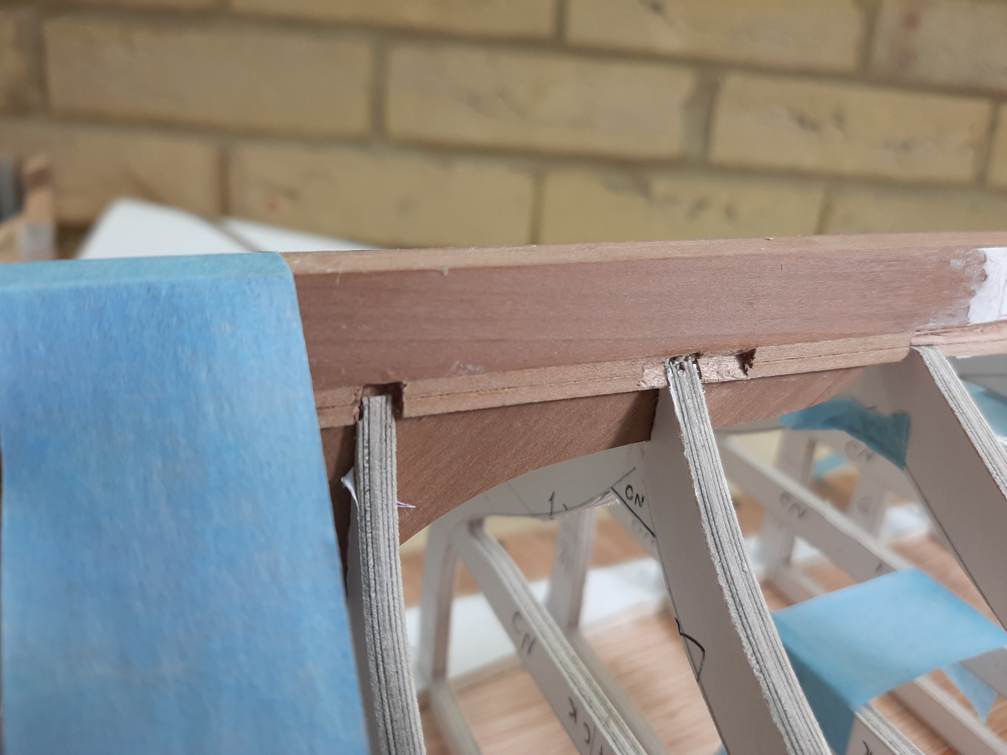
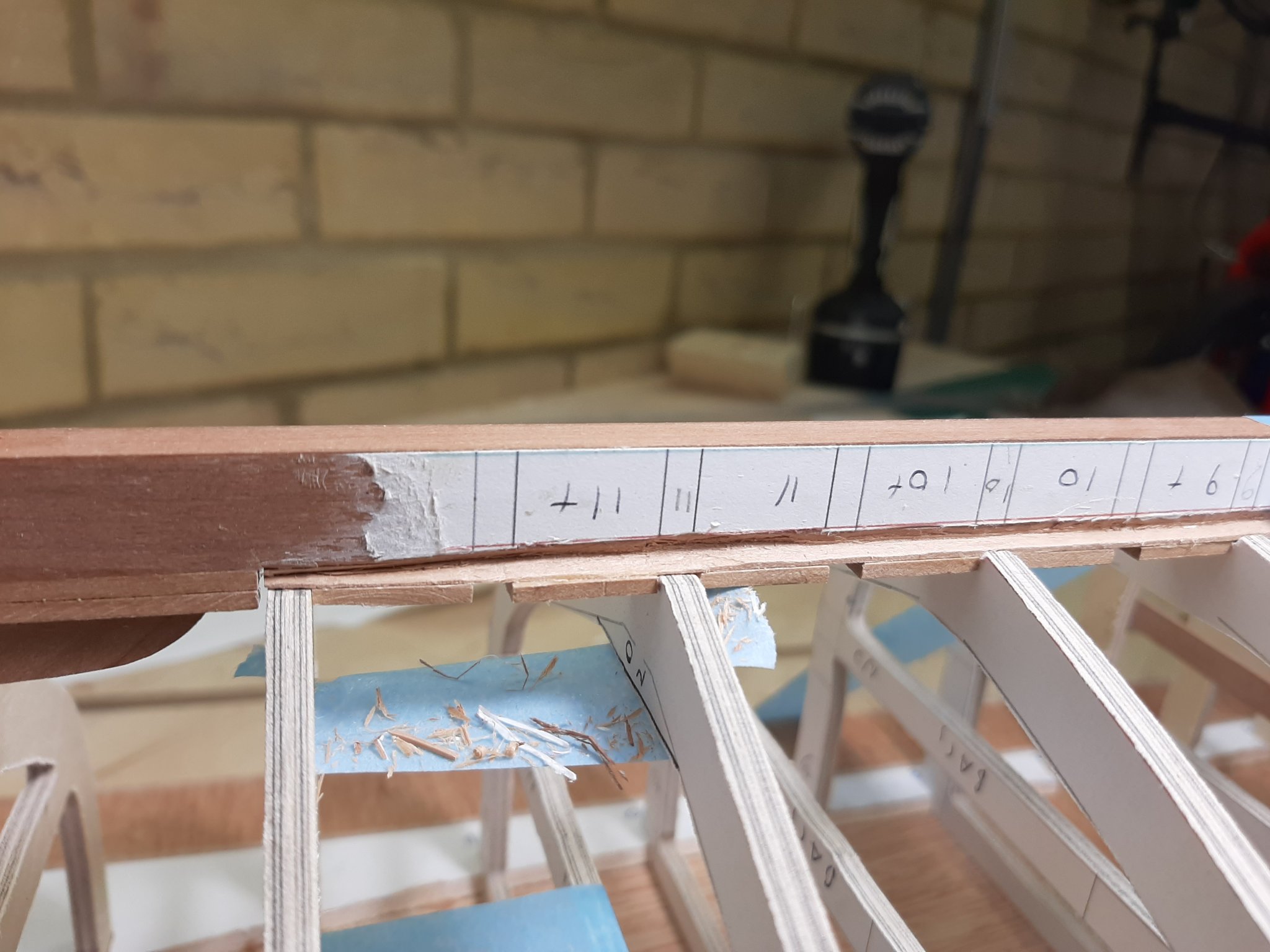
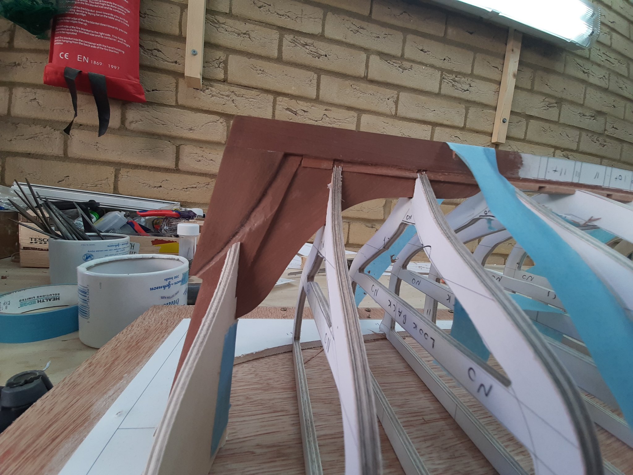
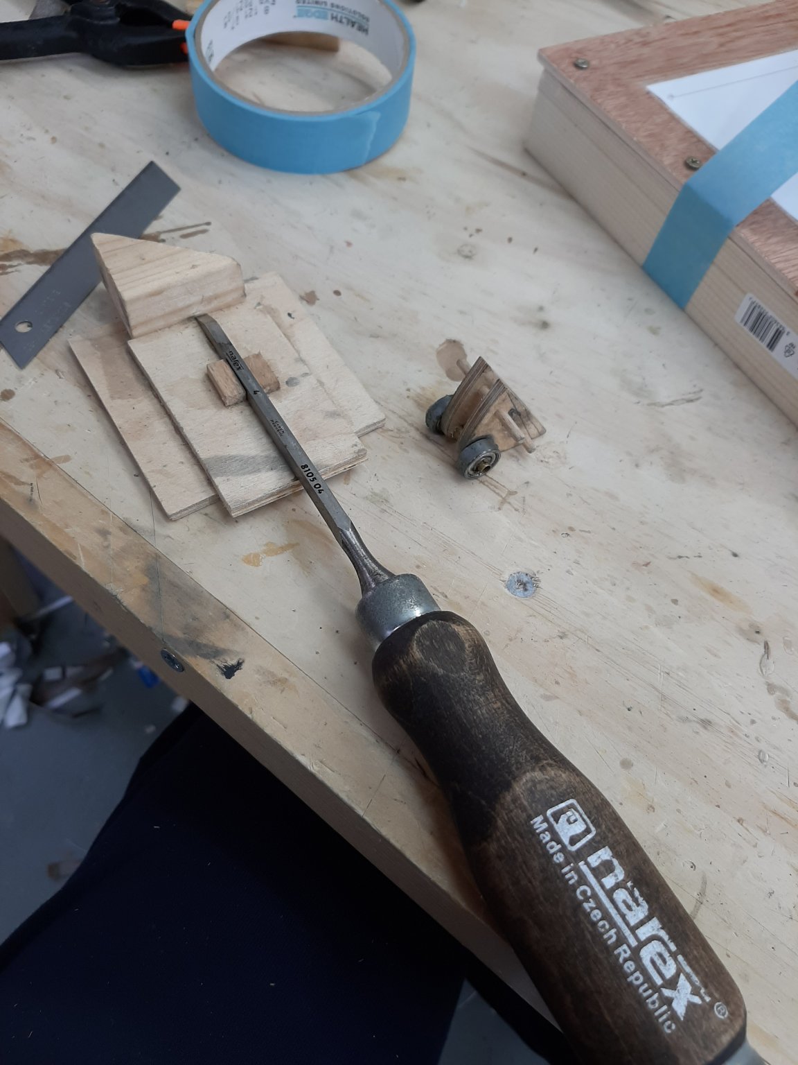
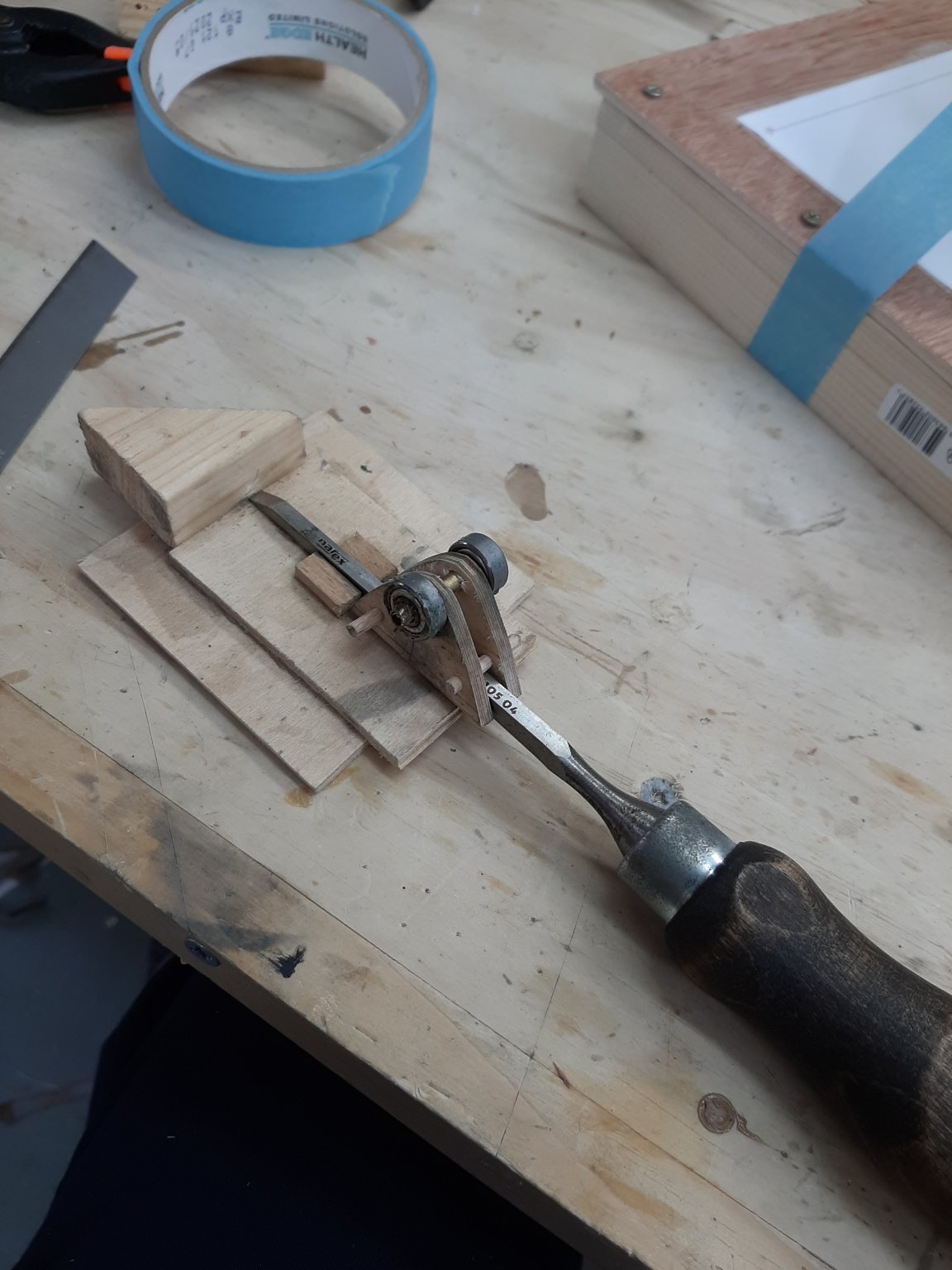
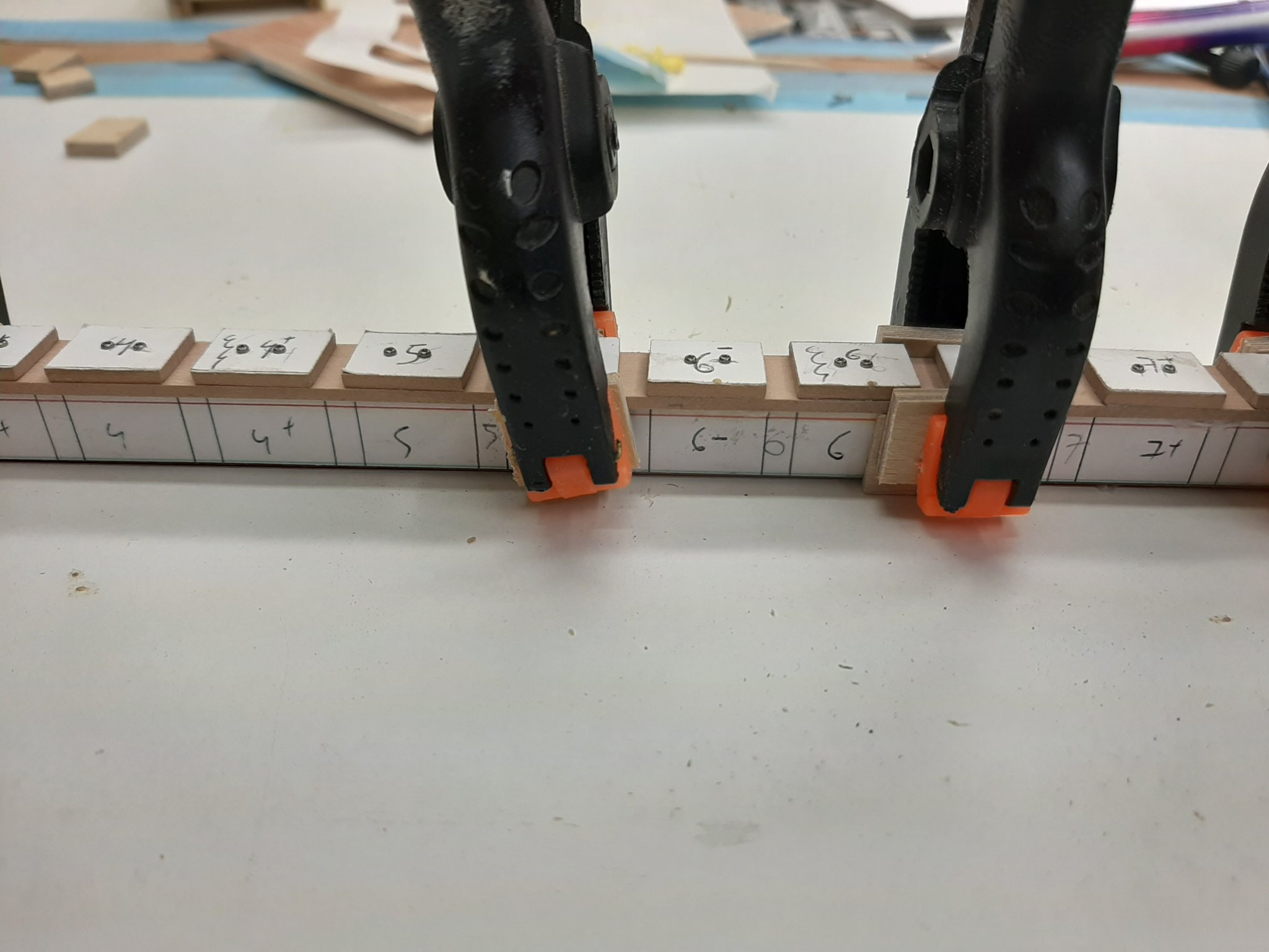
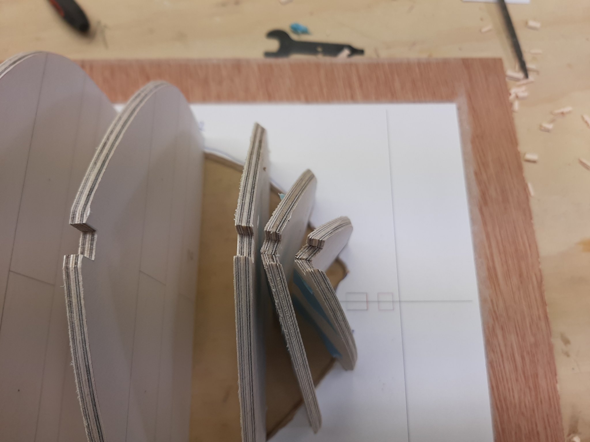
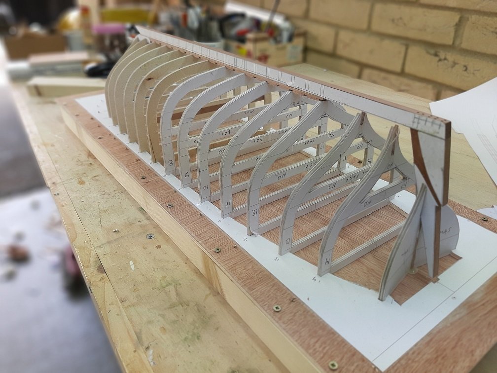
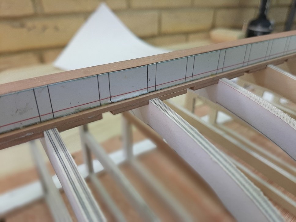
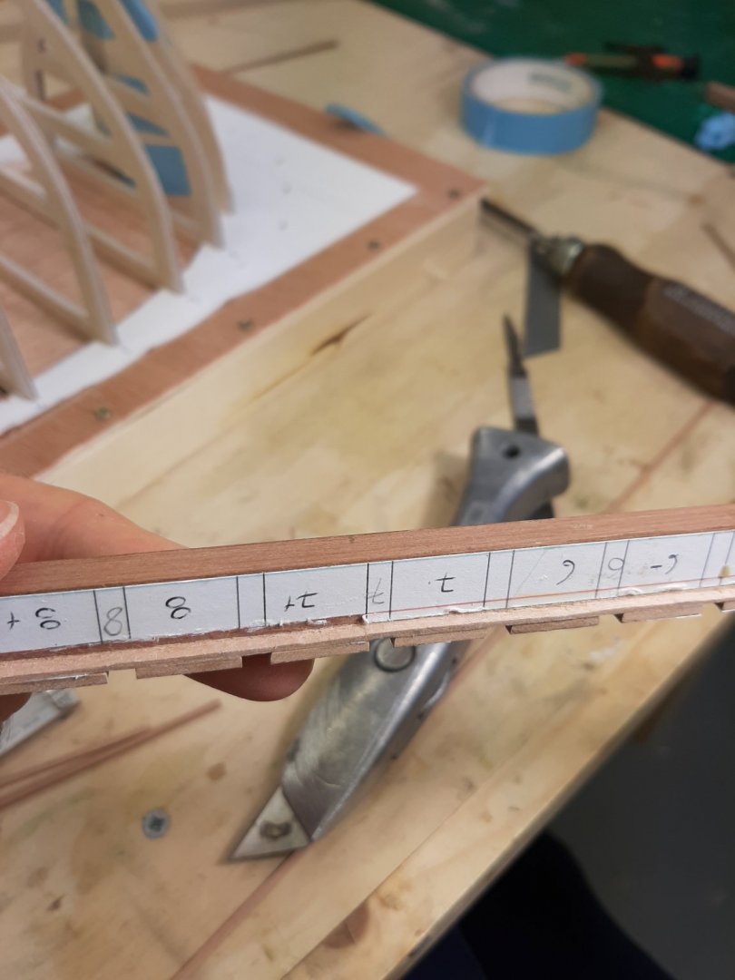
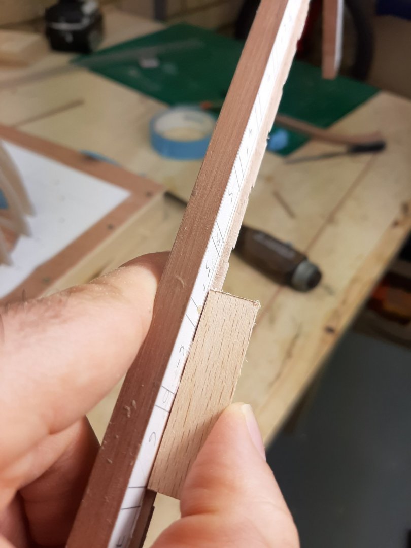
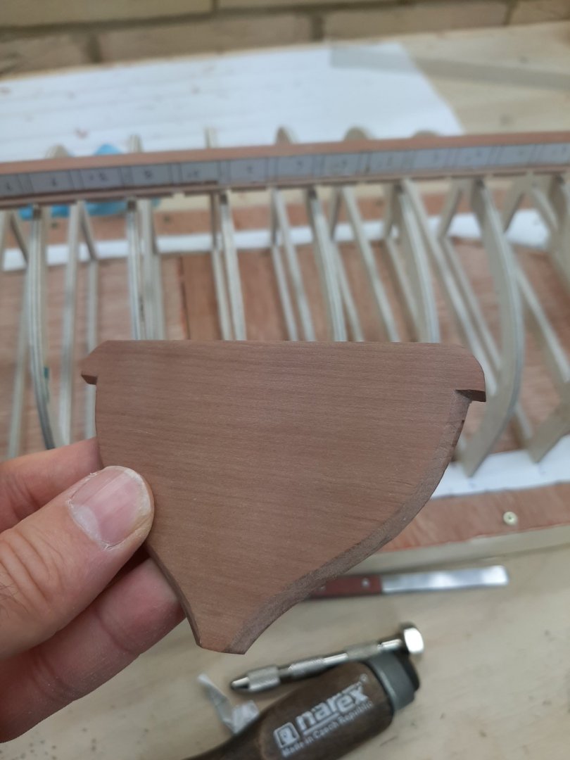
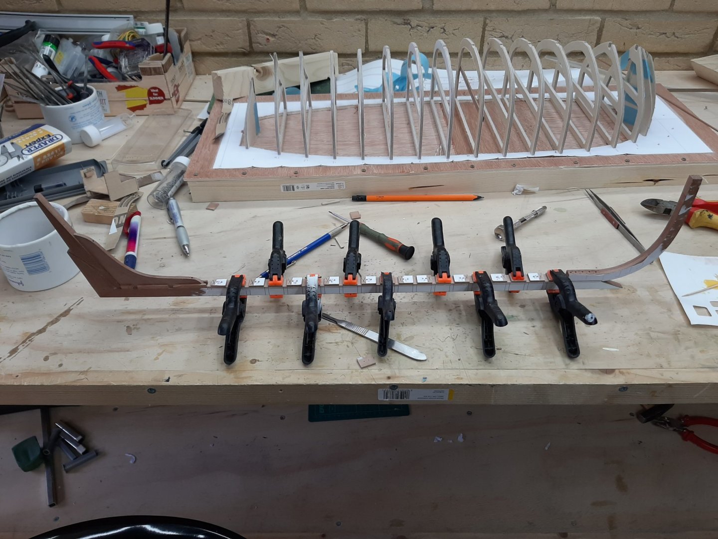
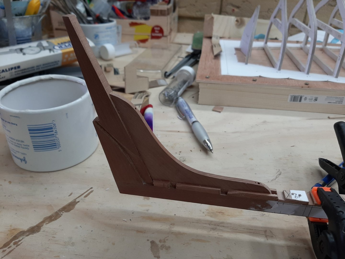
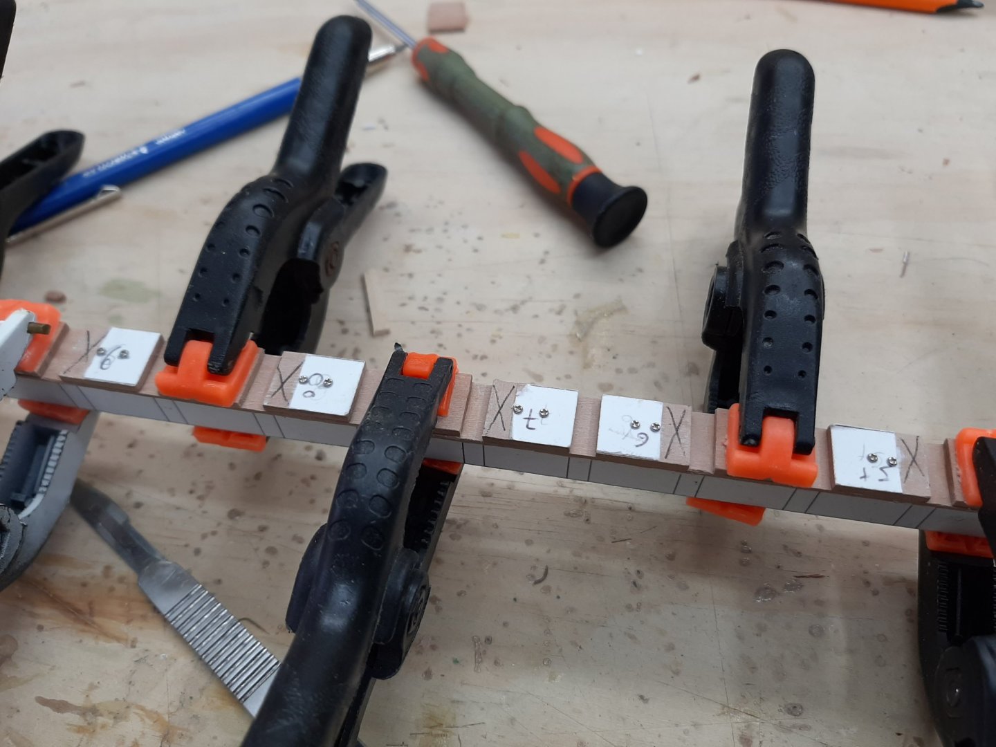
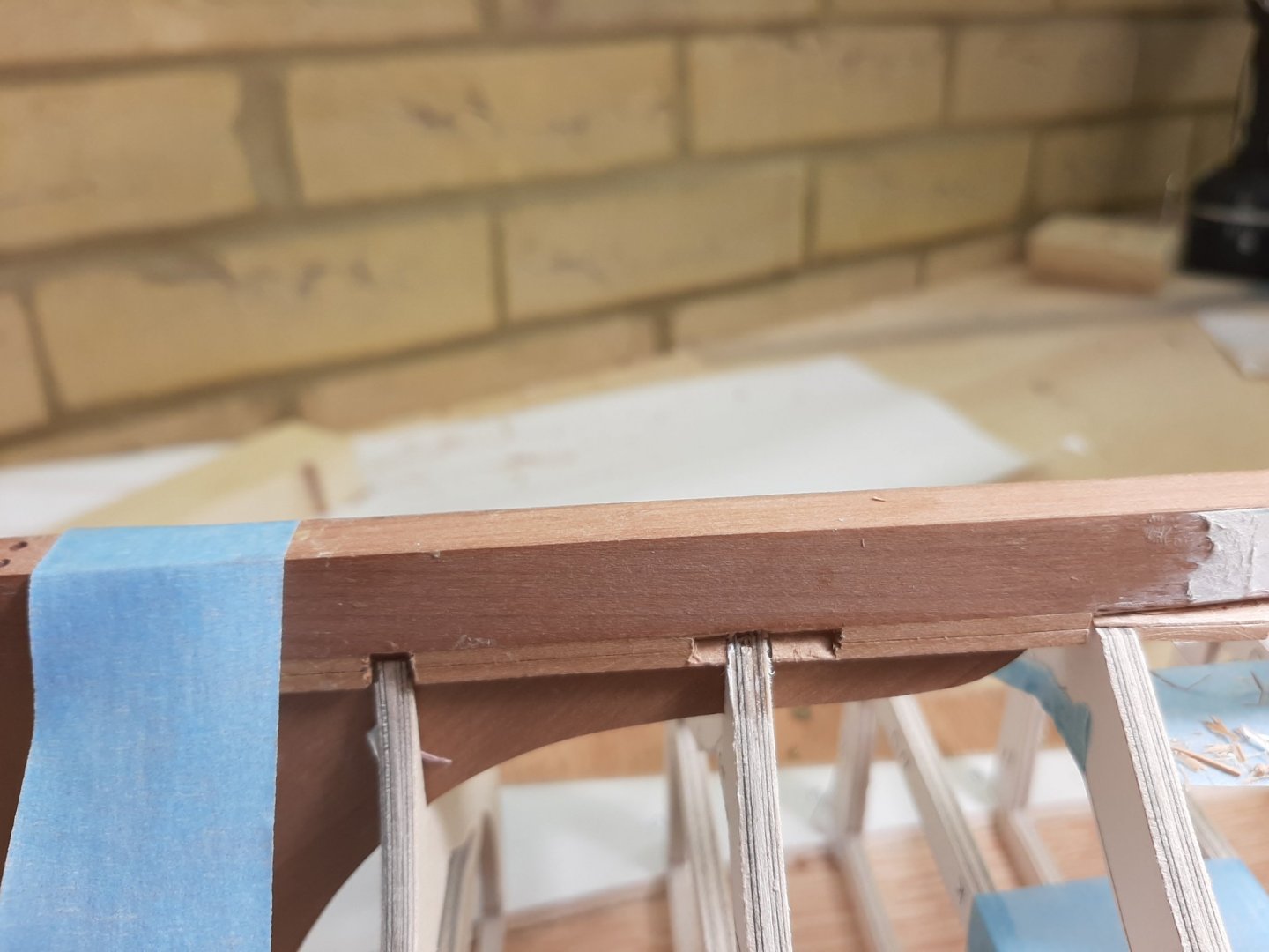
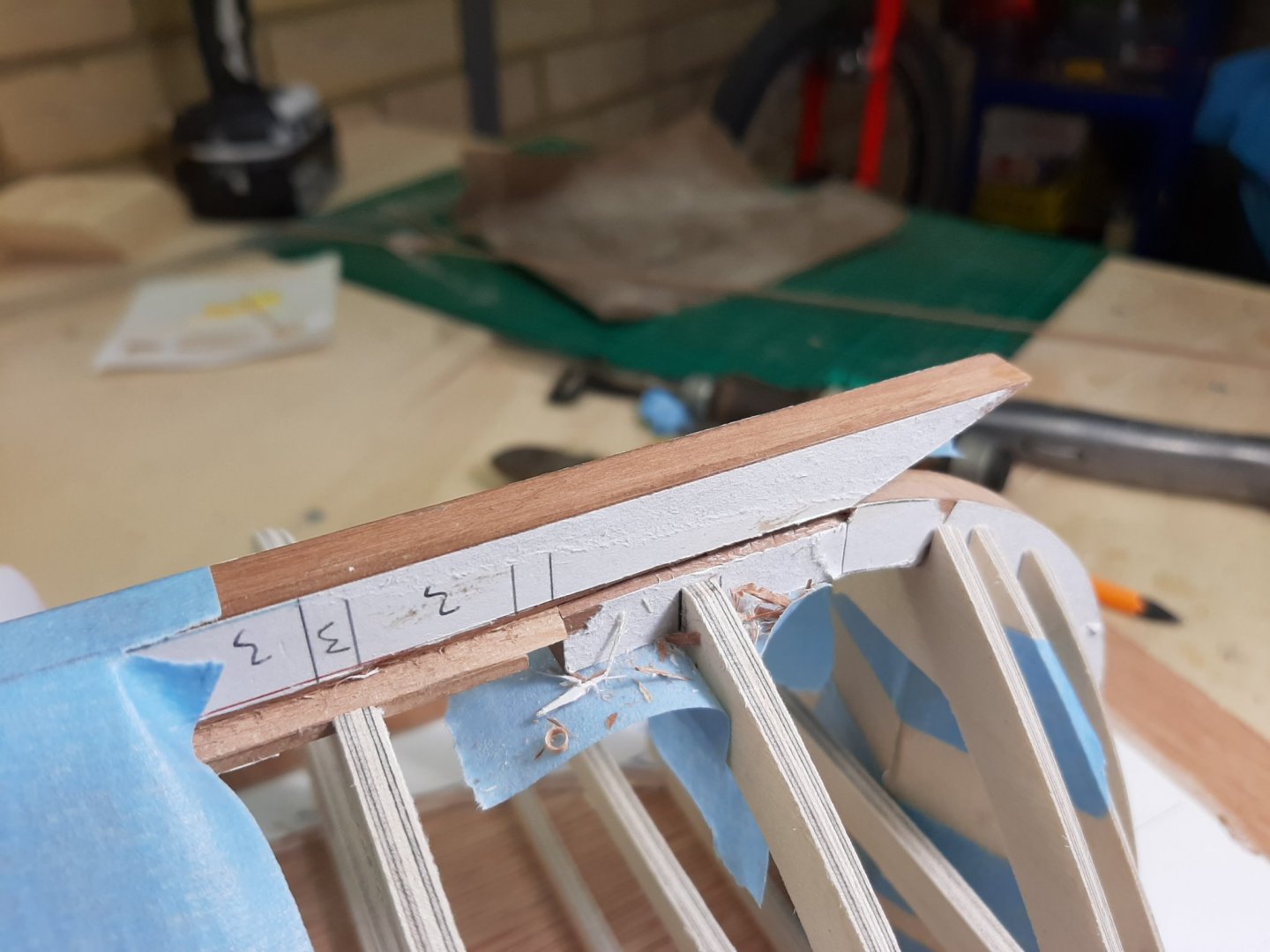
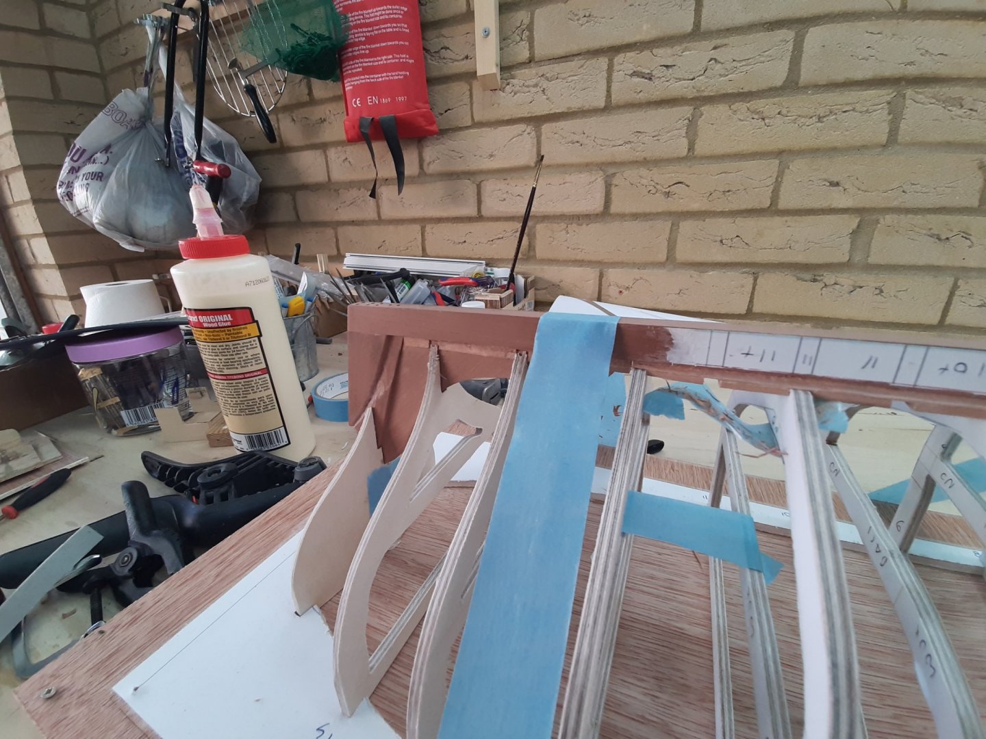
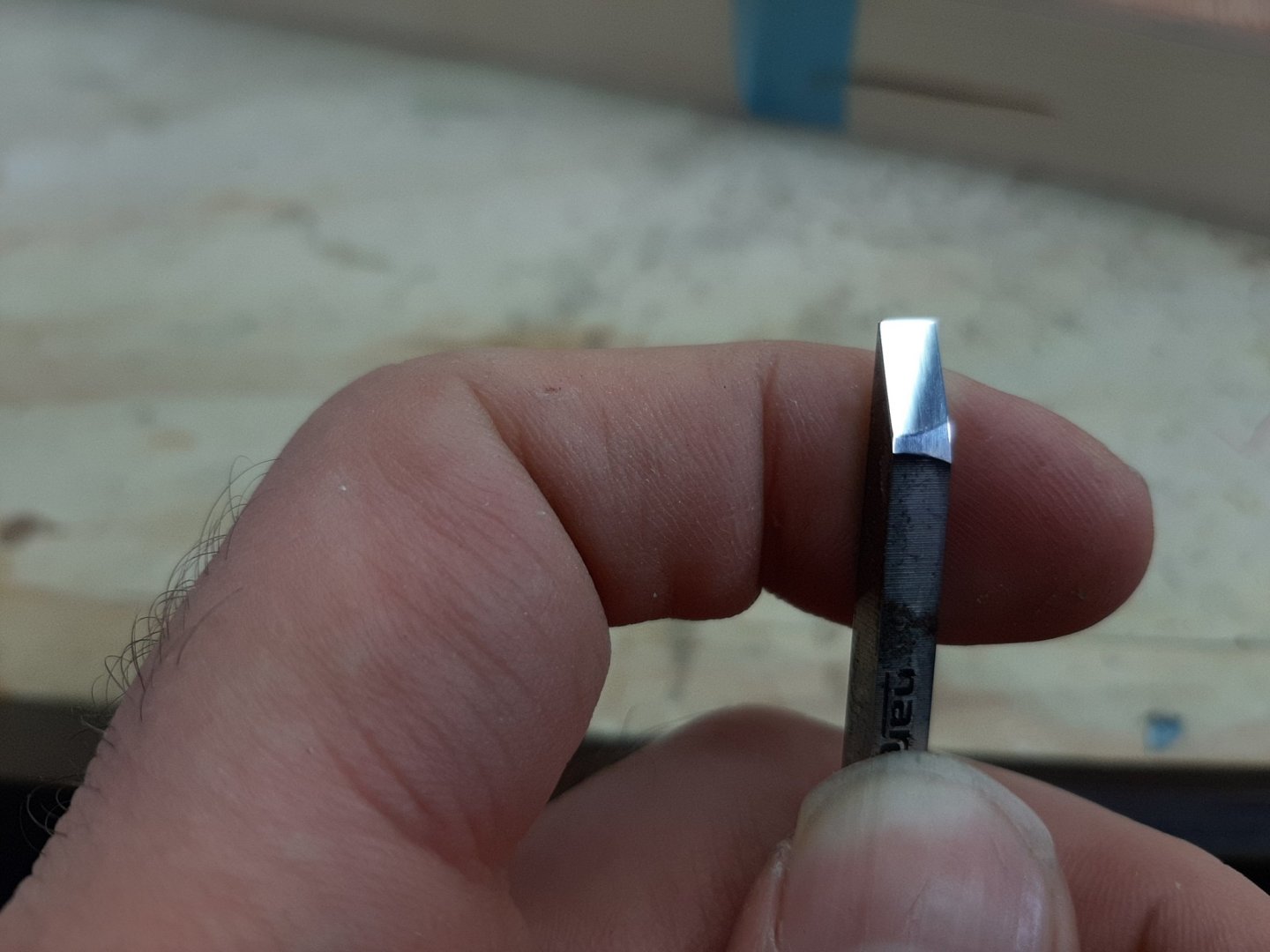
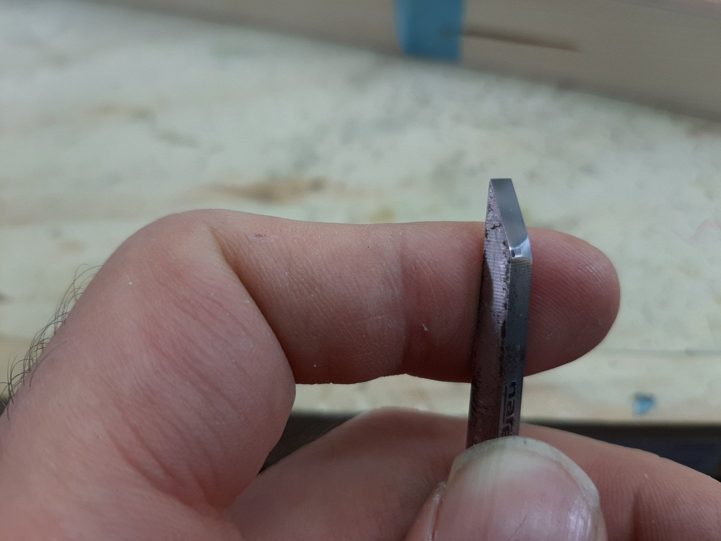
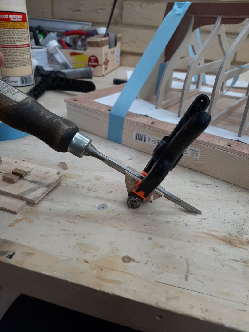
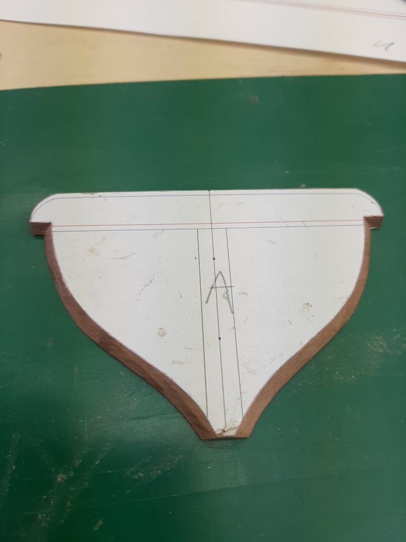
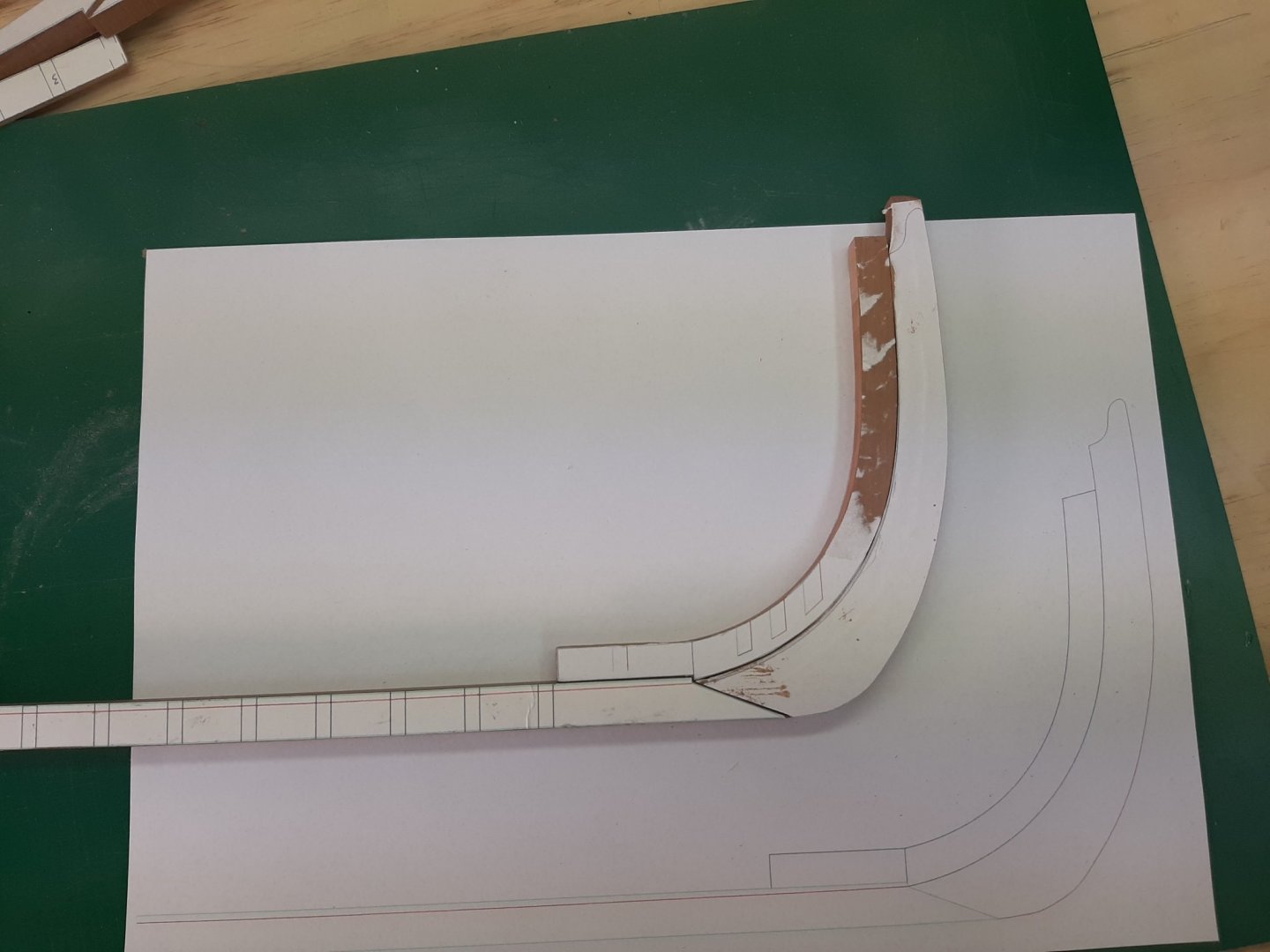
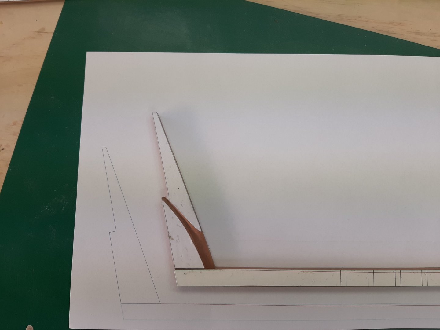
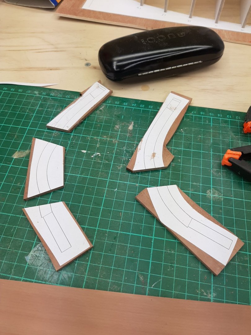
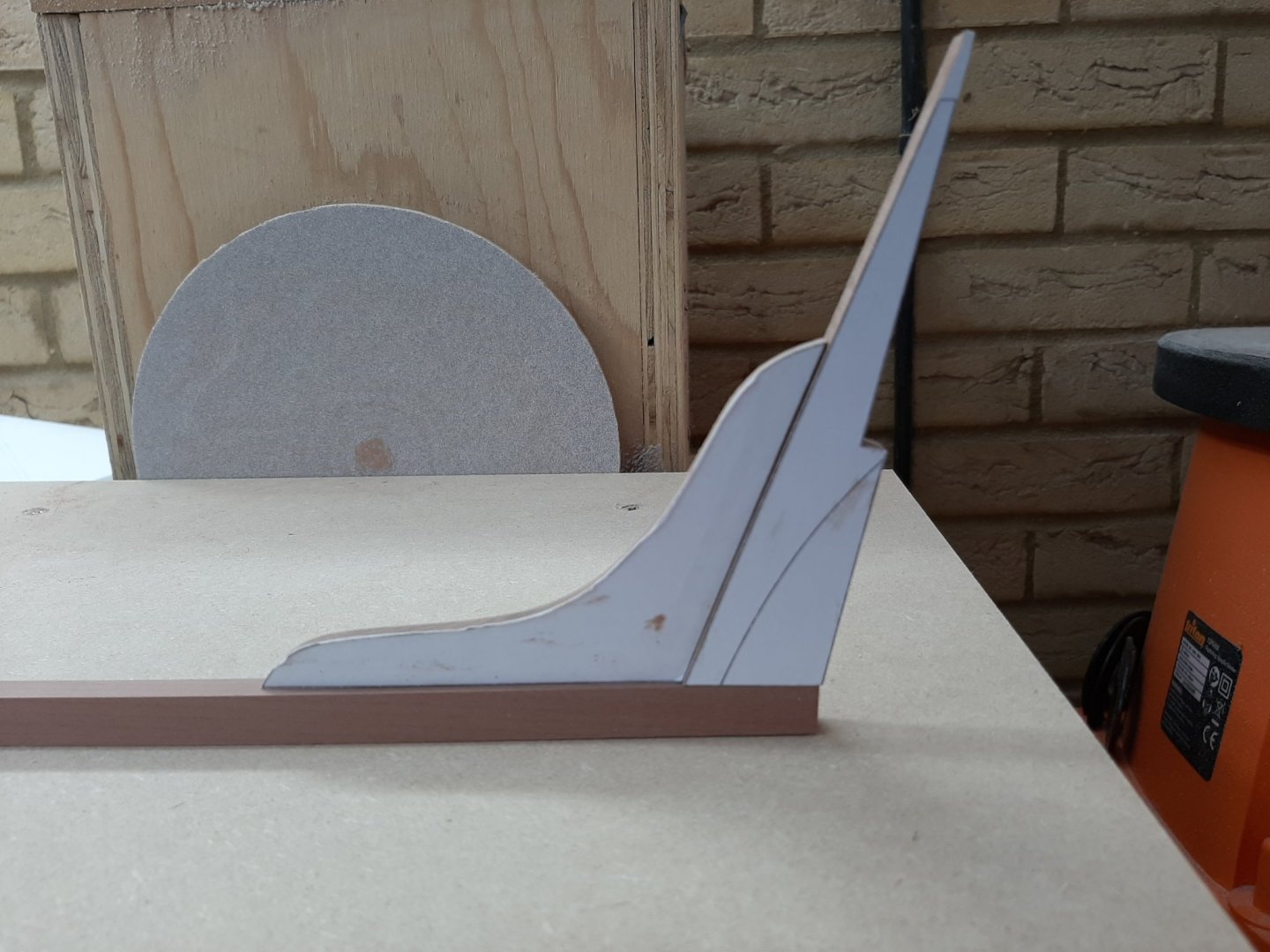
Some more progress, time for another update. Things are getting now a bit complex, I ll try to explain as best I can I have been able to work on and off on the boat so far but this is now becoming increasingly difficult, for the next few months, I ll be working 6 (and a bit) days a week so I expect things to slow down to snail pace. First of all, I decided to lighten the frames significantly. After the planking is completed, I will need to install steam bend ribs in between the frames and simply there will not be enough space for my hand to fit in. So, I cut large pieces off but left two cross beams, one at the base and one mid-frame that will be easy to cut off later on with the dremel wheel. The frames are still very solid. Next was the big job of cutting the rabet and shaping the hog. Now, this was properly difficult. It is impossible to follow the lines in the printed templates due to the large tolerances of my work but I am not too far off either. One interesting thing though is that the boat seems to have corrected my draft error. In my plans I had made the rabet a curved line but now it seems to have flattened. I started cutting the rabet mid ships where the planks meet the keel almost vertically, still however it made a difference in the fit. First photo is fit without rabet, second with. Difficult to capture but it is better. I then took a break to clean and sand the transom as it will soon need to be fitted. Lovely solid piece of pear wood. Then I thought I wood install the sternpost knee. This is screwed and glued. In the photo above I have also added some wood next to the knee, cutting notches for the two aft frames. Let me explain why: It is very important for the garboard plank to be fully supported along its bottom edge. The rabet is not enough, this is why the hog is needed to add more supporting timber. However, I made two mistakes. One is that I did not make it long enough. It should extend from the sternpost to the stem so that after bevelling, it will support the plank for all its length. So, I am adding wood to the stern and will do the same for a short distance at the bow. Second mistake is that I did not make it thick enough. Putting the bevels, it gets very thin. So the pieces that I had screwed on top of the keel, thinking they will be just temporary and used to hold the frames in position will need to be permanent. These will also help with the ribs later on as their position on the keel will be already defined. I have replaced the pieces that will not be used for gluing the frames, the ones that will be sacrificed are marked with an X, these will be removed with the frames after planking and replaced with nice wood without screw holes. Then I cut the rabet. Forget about plans! It was done with just eyeballing the angles and using small pieces of wood. This is where more wood needs to be added to support the gardboard up to the stem edge. I tried a piece of 2 mm cardboard to see how the planking would go. It looks ok! Then with a big push I finished the rabet. A bit more material needs to be removed from the sternpost Now, another task was actually to reshape and sharpen my 4 mm chisel. So far I have been sharpening it free hand but now the bevel is so curved that it affects its function. Now, a few years ago I had made a simple honing guide with scrap wood, metal and bearings. I dug it out and used it. Perfect results! The next photos show the jig and how curved the chisel was. Since I ve honed it to a mirror finish There is also another thing that is troubling me, the wood I chose for the planking. I chose 2 mm beech. For the Deben I had used 2 mm maple which was perfect and very pleasant to work with, easy to cut, easy to shape and bend. However, the beech I received is much harder and resists bending plus it is 2,2 mm instead of 2. The planks will be cut with a knife so I expect a big struggle. I hope at least that the wood will respond well to steam bending (it should really being beech). As Brexit is getting much closer I put in another big timber order from Germany. I will have enough lovely wood to last me for years, pear, beech and cherry. I hope it will not rot or cup with the huge variations in temperature and humidity we have hear in Britain. Regards Vaddoc


-
Couldn't do this Druxey as it was all covered up by the filler pieces. Maybe it will sort it self out when dry
-
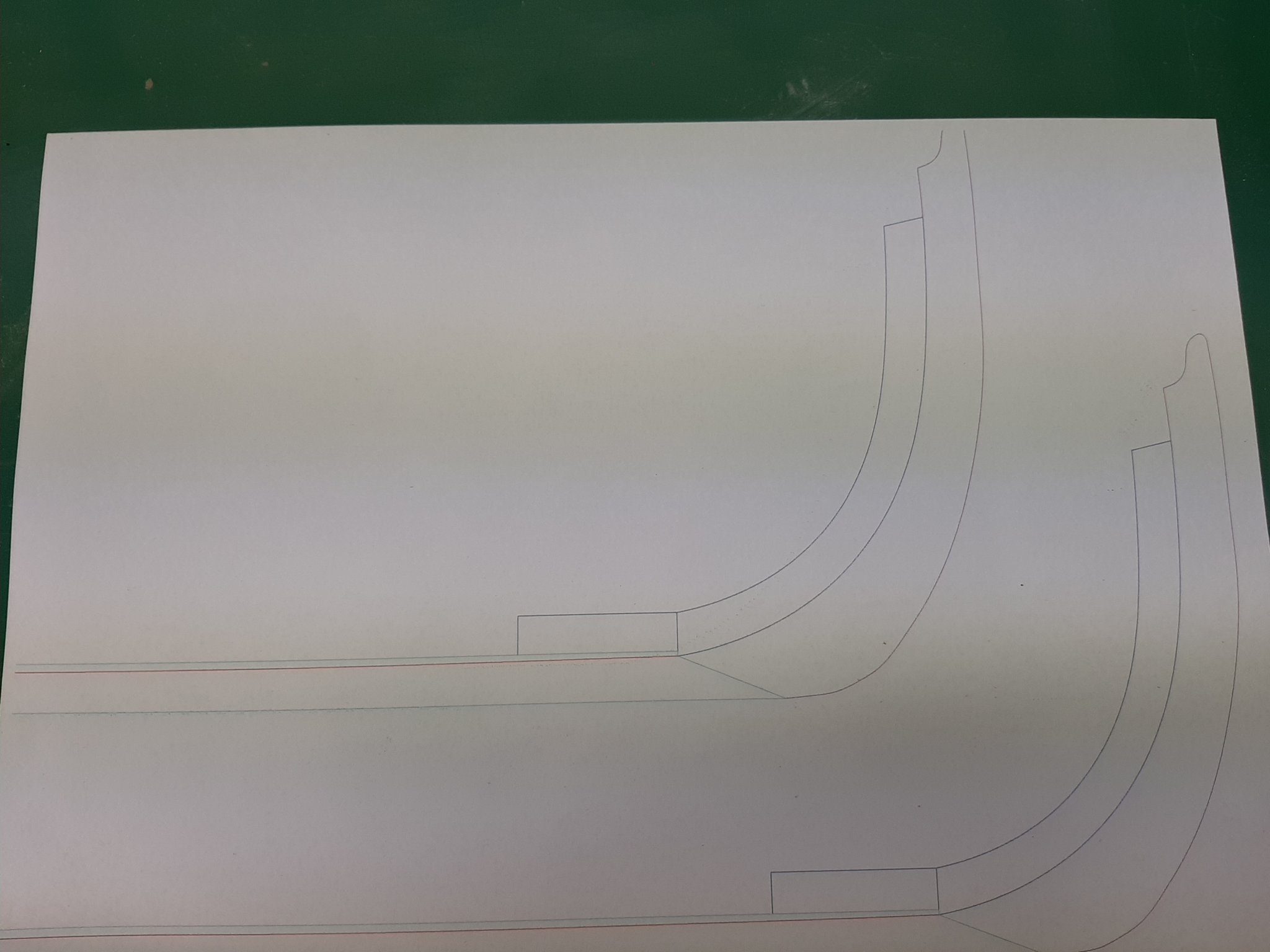
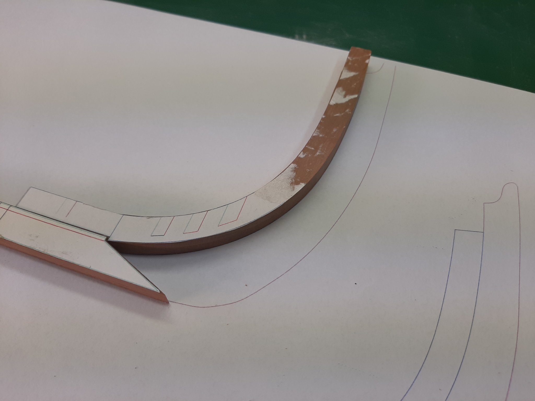
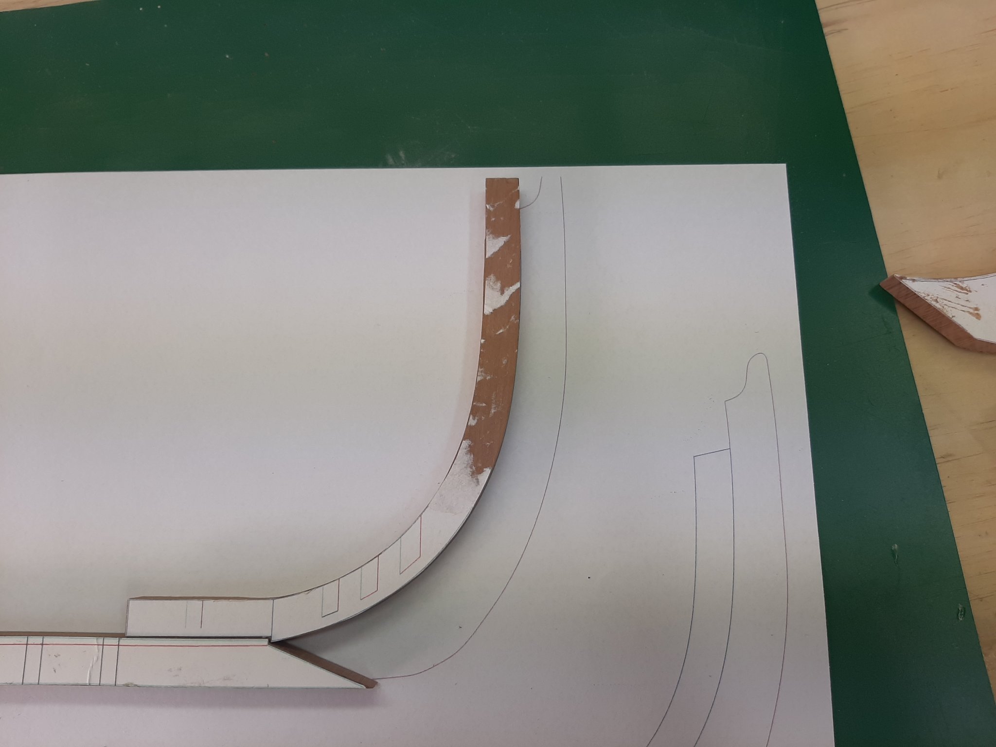
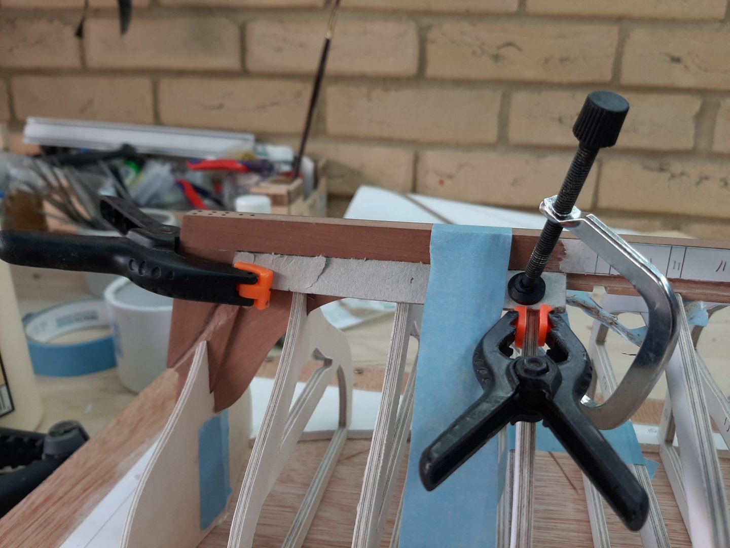
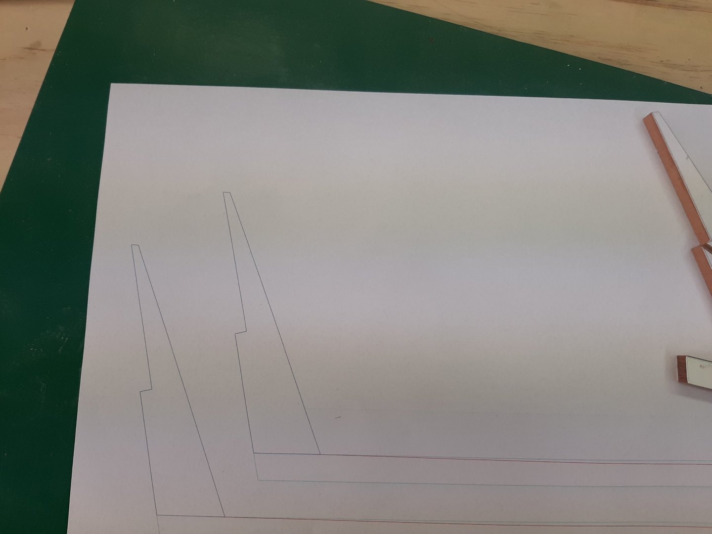
A bit more work done and time for another update. The boat is progressing very slowly. I cannot work as often as I would like and It takes me a while to remember where I left things, it is a pretty complex boat. Also building (kind of) the Chapelle's boat at the same time is not helping much...Still, some real progress made today. First of all, I printed out the patterns for the bow and stern to check how close to the CAD designs the wood pieces actually are. Happily, they are very close. I then finished the transom. I thought of leaving wood on for a safety margin, as I think is standard practice in actual boat building, however it is much easier to sand the transom now. I then glued and screwed the sternpost to the keel. I first drilled 0.7 mm holes to the keel, then taped the sternpost to the keel and hand drilled the rest of the way in the sternpost. Then I counterdrilled the holes in the keel to accept the head of the screw and screwed the 2 pieces together, with PVA in between. The joint is rock solid, the holes will be filled later on. The procedure was repeated for the stem but here I hit a snug: The keel will need to be notched for the rabet and might hit the screws if placed laterally. So I drilled new holes, this time at the midline. The stem looks like Swiss cheese but I ll fill the holes later on. Then, I made again the hog or apron as the previous piece had some dents. Now, I had to figure out a way to make sure the frames are correctly placed/spaced but also that the keel is secured to the frames but in a non-permanent way, so that the frames can be removed later and replaced with ribs. The way to do this will be to screw wood pieces to the apron and glue the frames to these pieces. Then unscrew these when it is time to remove the frames. So here it goes: The previous apron was cut up and wood inserts were made to go in between the rib spaces. The sides that will be epoxied to the frames were marked. Then these were lightly glued to the paper template of the apron Now, the keel has a slight bend laterally so i used some clamps to bring it in line with the apron..It straightened a lot Next the filler pieces were removed, the paper template removed from the apron which was then sanded clean. Then the pieces were screwed on again and the assemble glued and screwed on the keel This did not go as well as I would like because the apron, being very wide and only 2 mm thick, cupped from the liberal use of PVA. I do not think this will be a problem as it could uncup when dry but either way, a lot of it will be chiselled away and it will be invisible under the floors. Regards Vaddoc


-
Hi Noel I ve been using Rhino for many years. The real objective is to get a smooth (-ish) outer skin. To do this, you need to first define the rabet at stem, keel and sternpost, define the edge of the transom and the sheer line. These are the boundaries of your outer skin (surface of planking). Then draw all your lines, fair them (ask the computer to do it), then choose the most promising and use these to adjust all the others. Then again choose the most promising lines and try to get an outer surface. When you accomplish this, you are pretty much done. You can get any frame of any thickness including bevels by simply projecting vertical lines to this surface. However don't get too obsessed with CAD accuracy, it is very difficult to transfer it to cut wood as I am actually finding out as we speak! Regards
-
Long time no see Patrick! Nice to have you back. Sapphire came out fantastic, too many lovely details, took a while but I finally figured out the two level engine room. Jewel of a model Vaddoc
-
Well, just to mention that I have been doing all my model work with the Dremel moto saw bought new 6 years ago for £67. Still going strong, cut 8 mm pear sheet with relative ease- had to take it slow cross grain. Can't go wrong with the combination of a scroll saw and most importantly a large (at least 200 mm, better 300) disc sander.
-
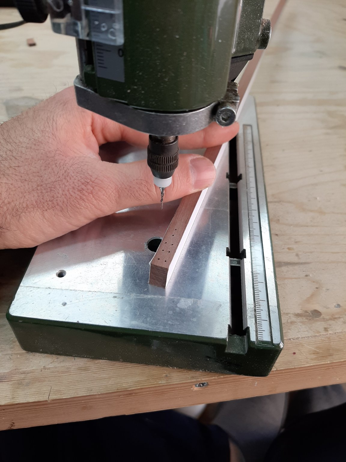
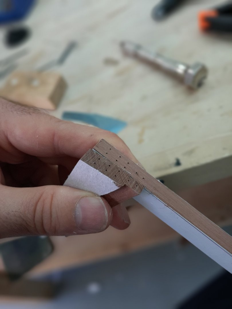
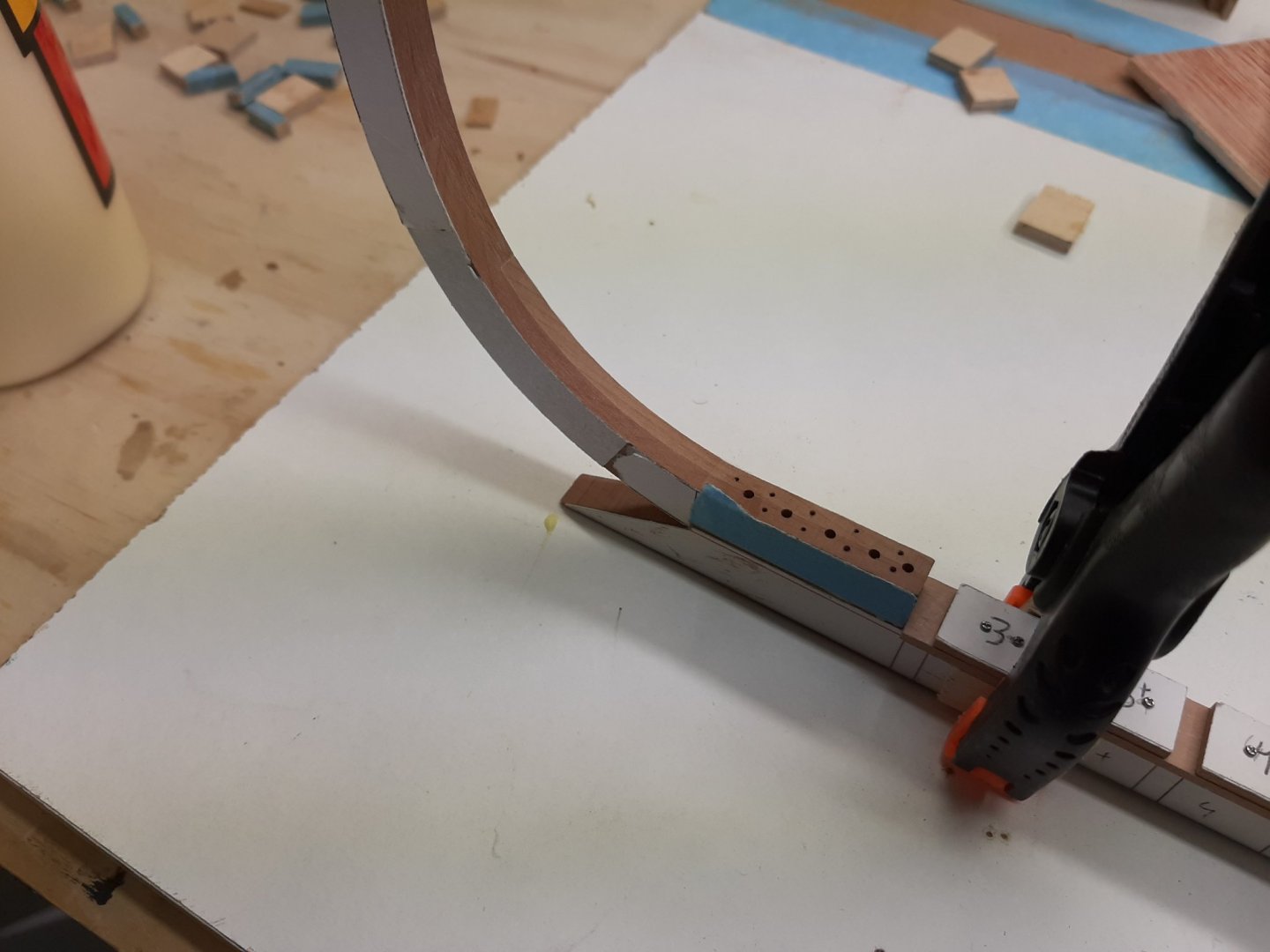
Thanks Bedford, indeed this is an option. I have several sizes brass or steel pins from 0.5 mm to 1 mm or I could use micro screws. The planks could be glued or tree nailed to the ribs. I just would like to investigate whether threaded brass wire alone (I think 0.8 mm) could be used. There would be 10 threads in each 2 mm plank and frame/rib which should be plenty strong. No holes to fill, just the wire to cut flush. The challenge would be to re use all the holes, this means not a single rogue one. Statistically this is impossible as there would be 2000 holes or so but I ll give it a go. I am thinking of using initially 0.5 mm pilot holes with 0.5 mm steel pins to go through the lapstrake overlap and into the temporary frame. The pins would later be removed, the hole opened up to 0.6 or 0.7 mm going through the permanent rib at the same time and all secured with the threaded wire. Plenty to go wrong! 1mm wire behaves fine but 0.7 mm tends to twist along its axis almost to braking point. I hope 0.8 mm will be safer while still acceptable in scale. Regards Vaddoc
-
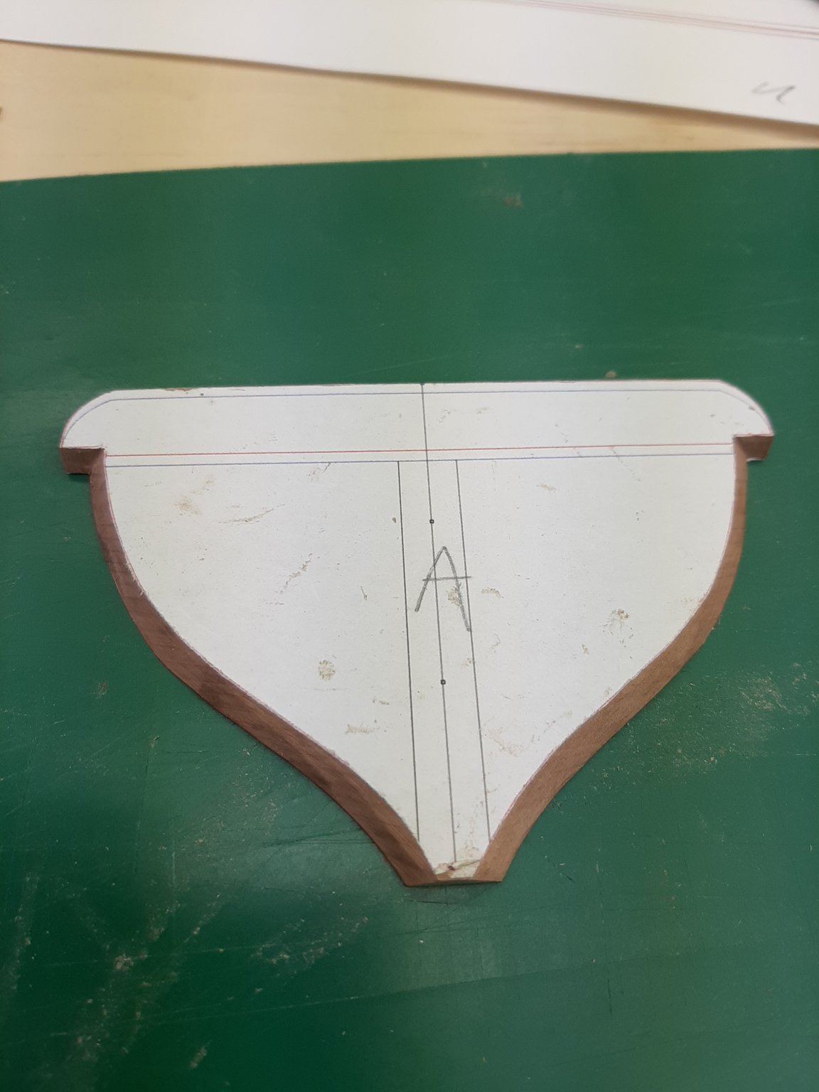
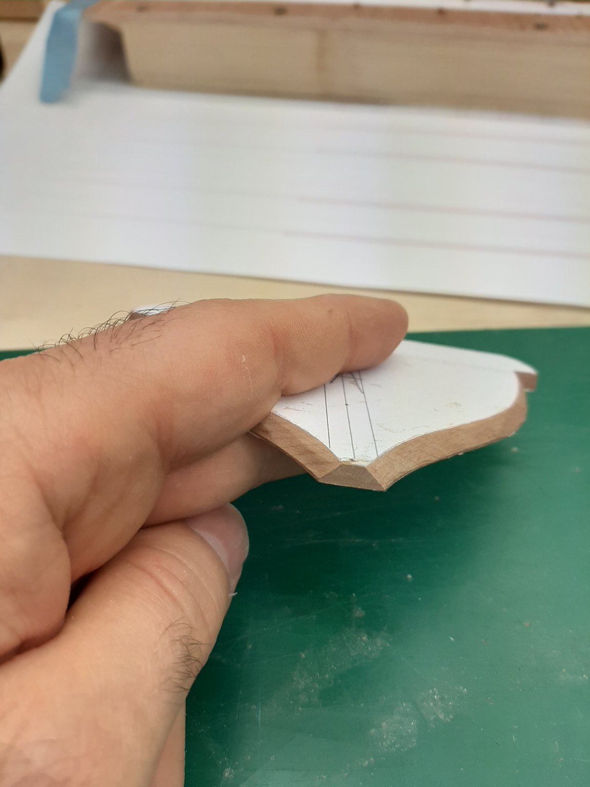
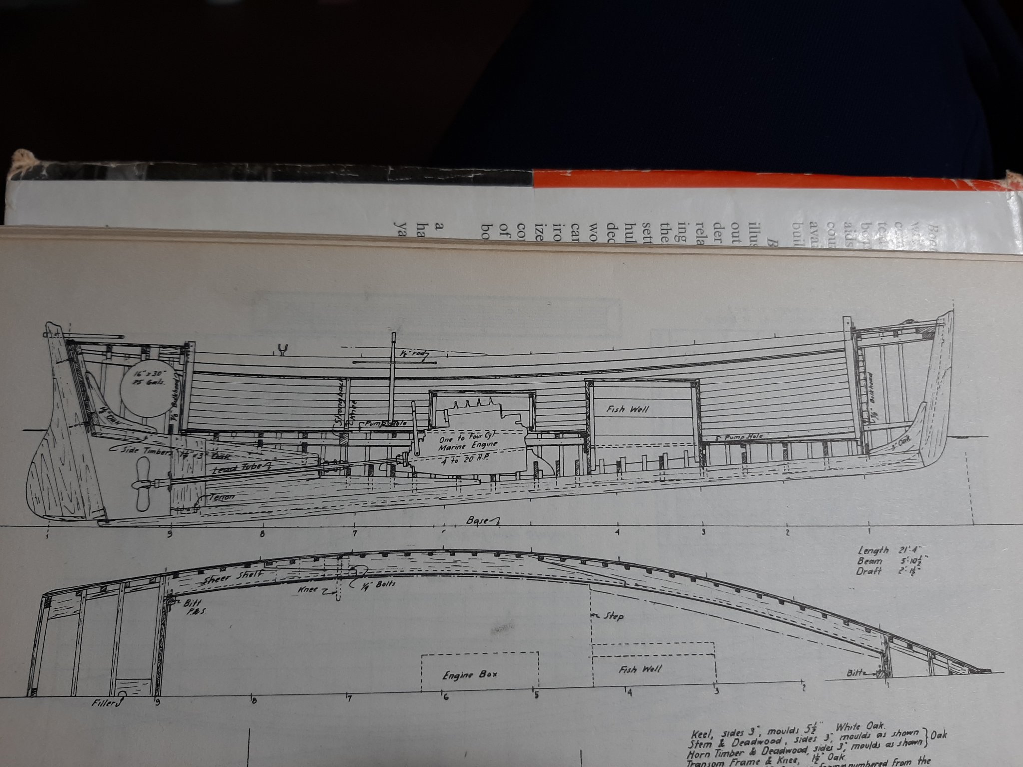
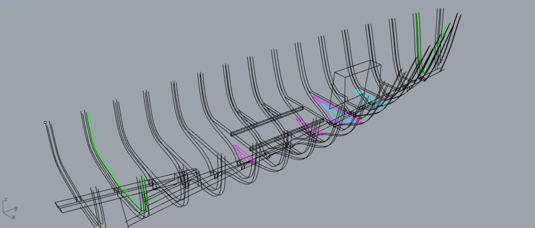
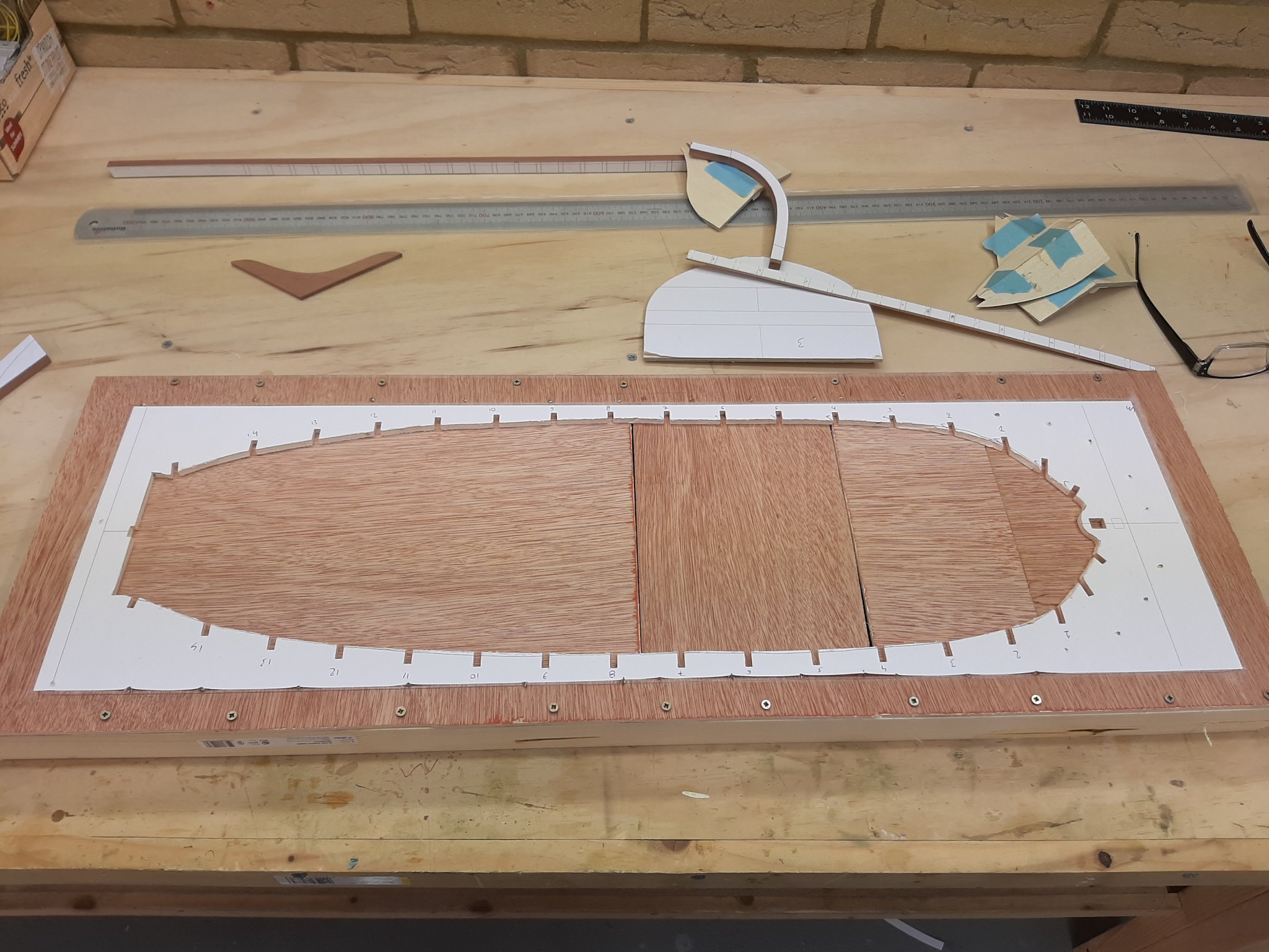
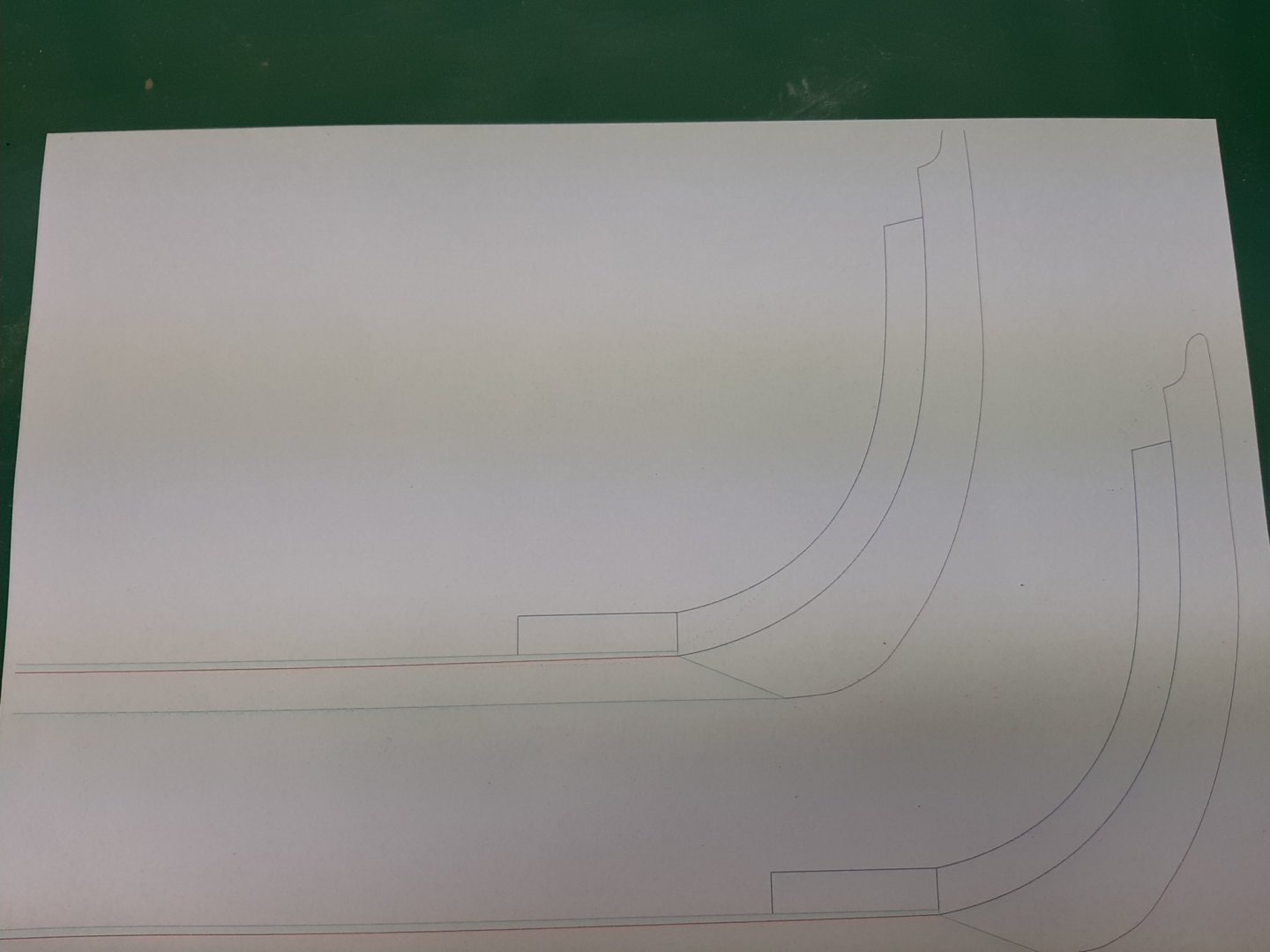
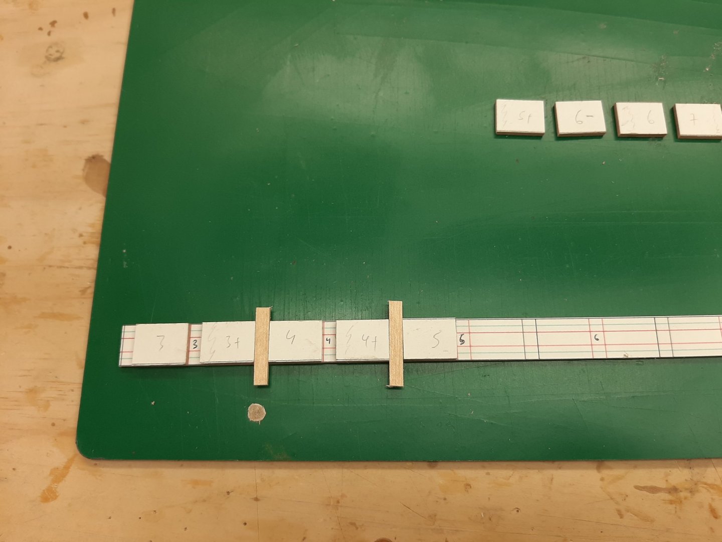
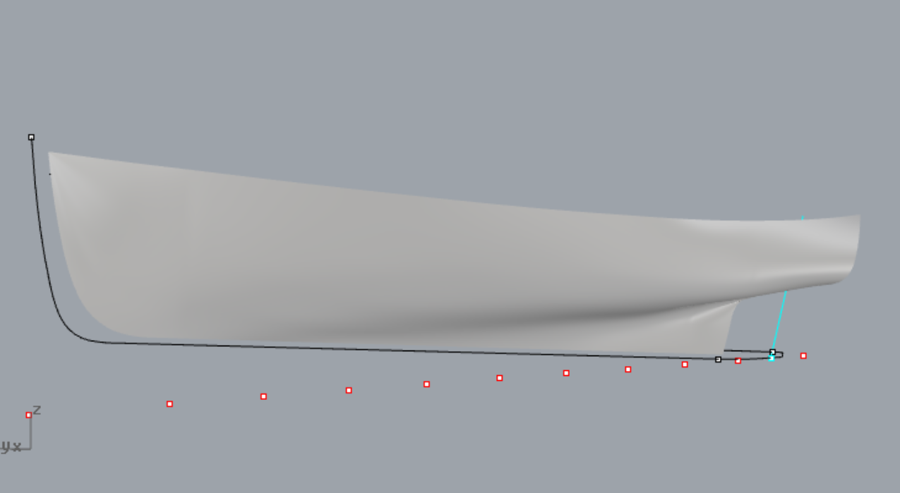
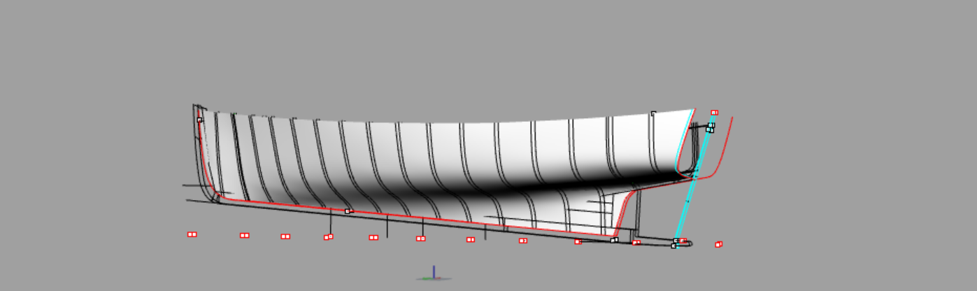
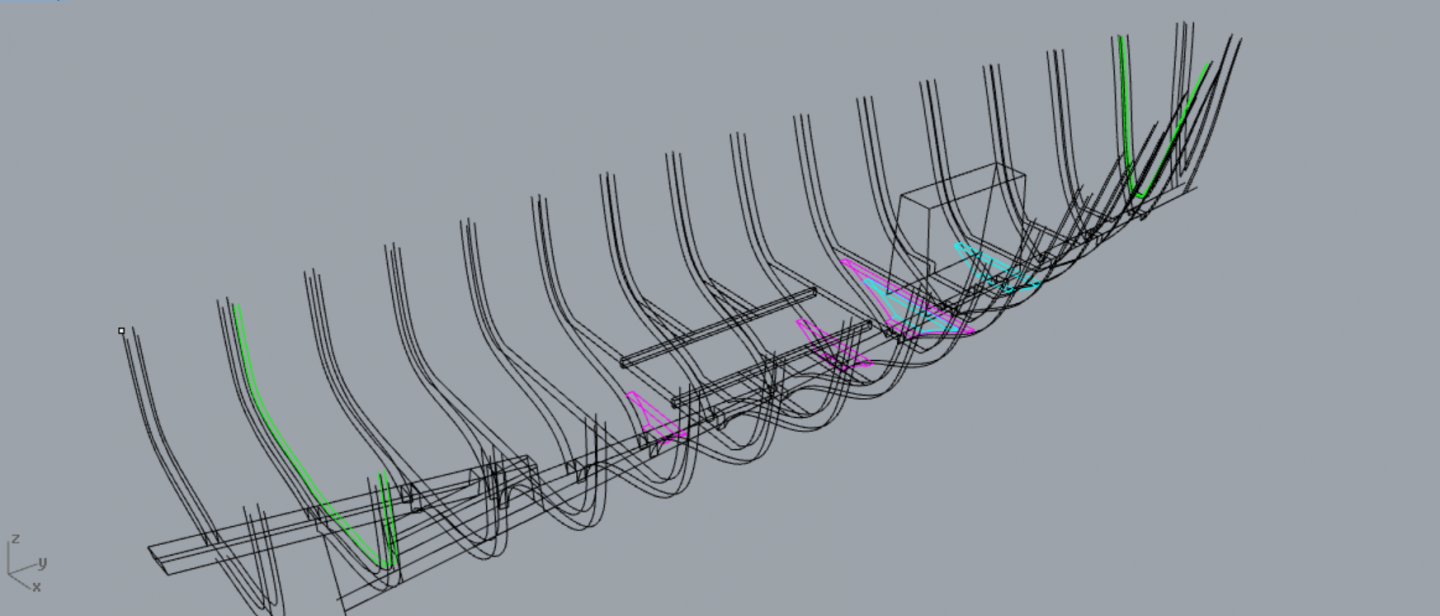
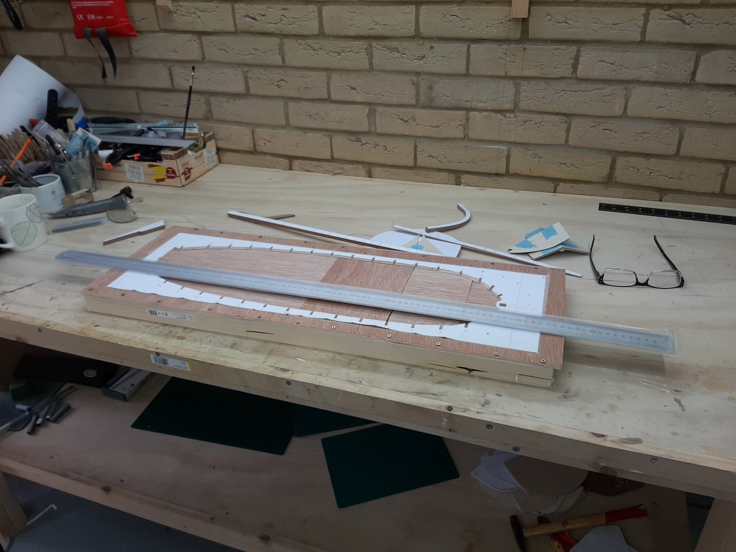
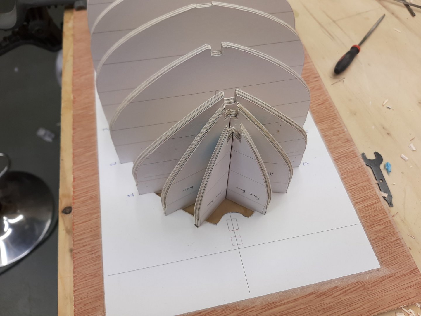
A few moths back I got Chapelle's "Boatbuilding". It is a lovely book and an enjoyable read. The Launch drew my attention due to the simplicity of its construction and I started drafting it on CAD at the same time as I was drafting the Yawl. Now, the Yawl will be clinker planked but the Launch would be carvel. I just thought it made perfect sense to build both alongside so I could have my fill of spilling planks. Or maybe just double the frustration, time will tell! Now this decision is not entirely unreasonable. Most of the CAD plans are ready. I will not use temporary frames and will not use steam bend frames. I intend to use solid frames and these will be made from the left over plywood that I laminated for the Yawl. Eitherway, the frames in this boat are entirely hidden from view. I will use either cherry or pear for the keel and maybe beech for the planks, if there is enough left over from the Yawl. I think however that in the end I will need to order some more wood from Germany and maybe best to do it before Brexit kicks in. We ll see Same as with the Yawl, I am thinking of using threaded brass wire to hold the planks. I ll need to experiment a bit though. A few pictures. This is the boat. There is nowhere to sit on-this boat is for hard work only This is the half hull surface Since the frames will be solid, some deviation from the plans is needed to accommodate the engine bay and the fish well. There will be plenty of floors and I had to move the bulkheads a bit. There is still a bit more work to be done as well as to make some form of a jig. I think this should be easier to plank than the Yawl, not only because it will be carvel planked but also due to the much less curved bow. Time will tell! Best wishes Vaddoc

-
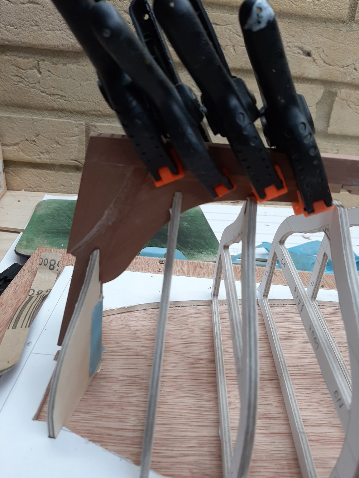
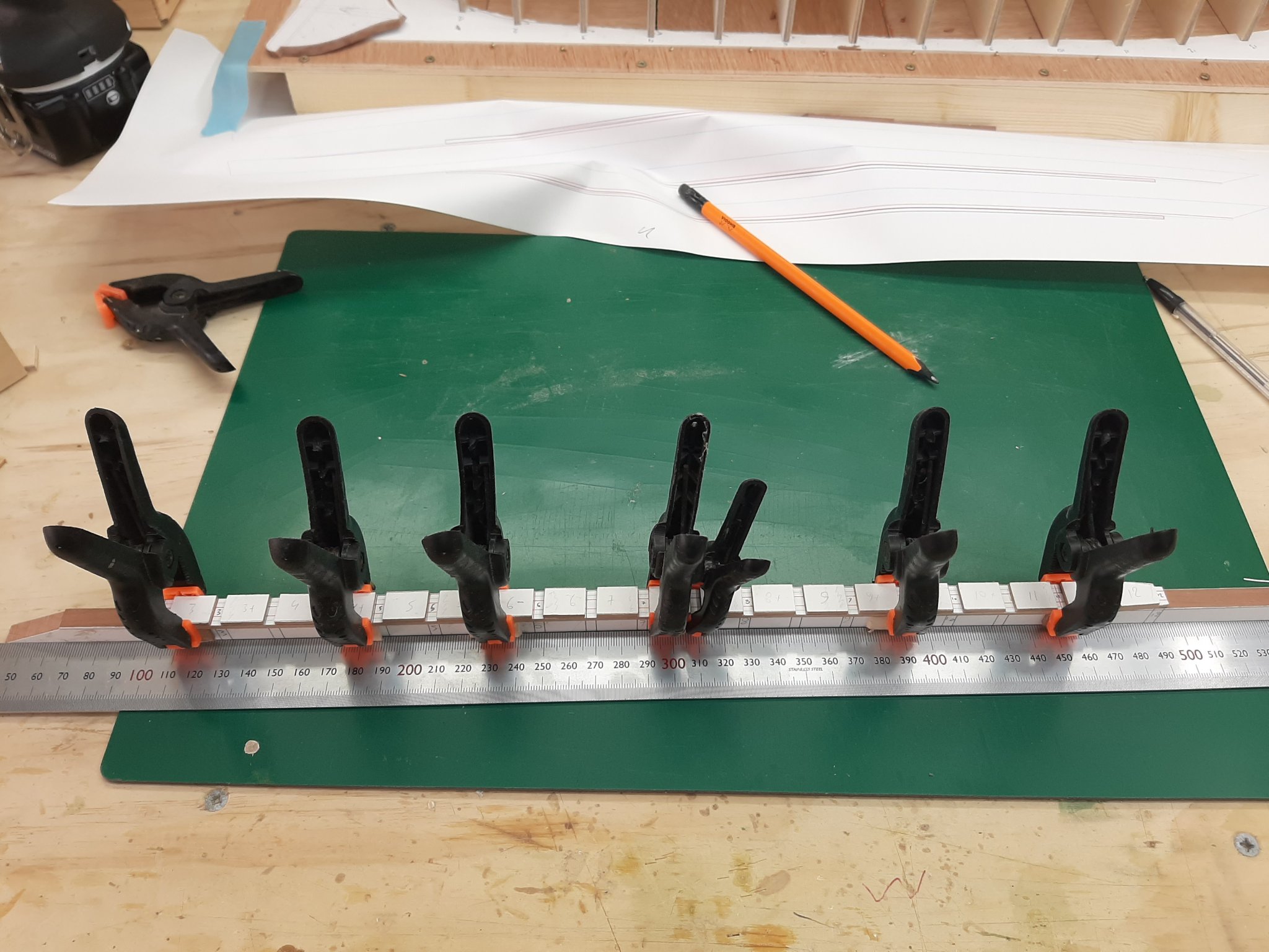
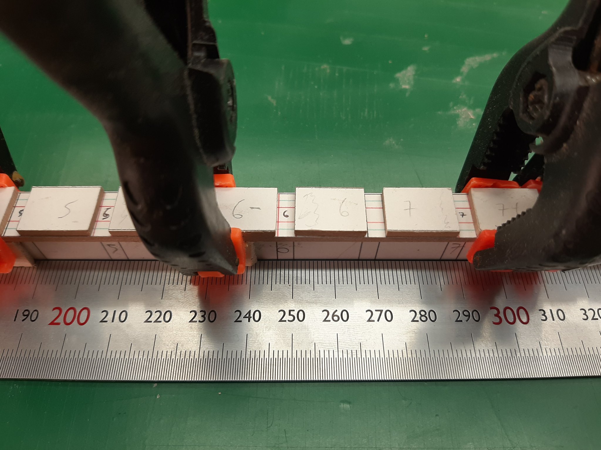
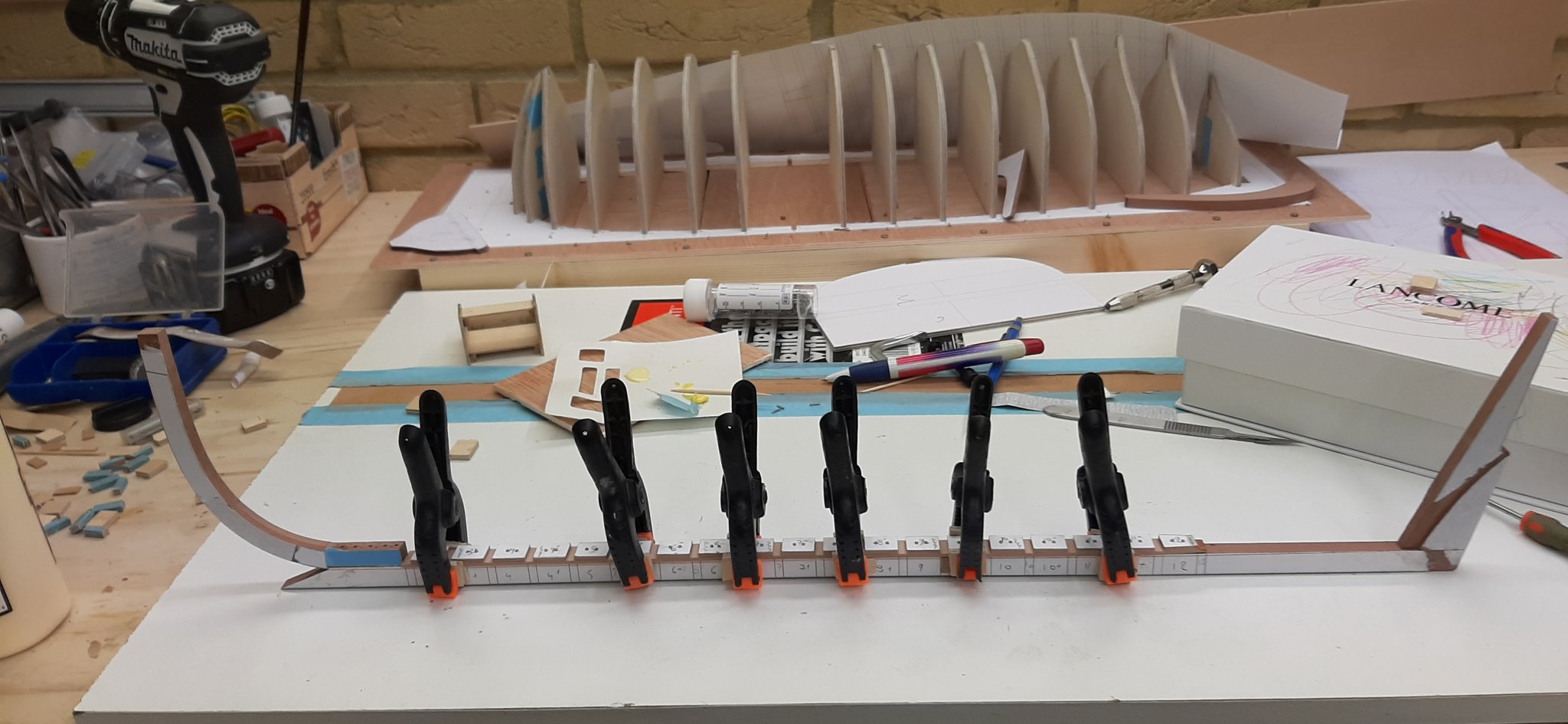
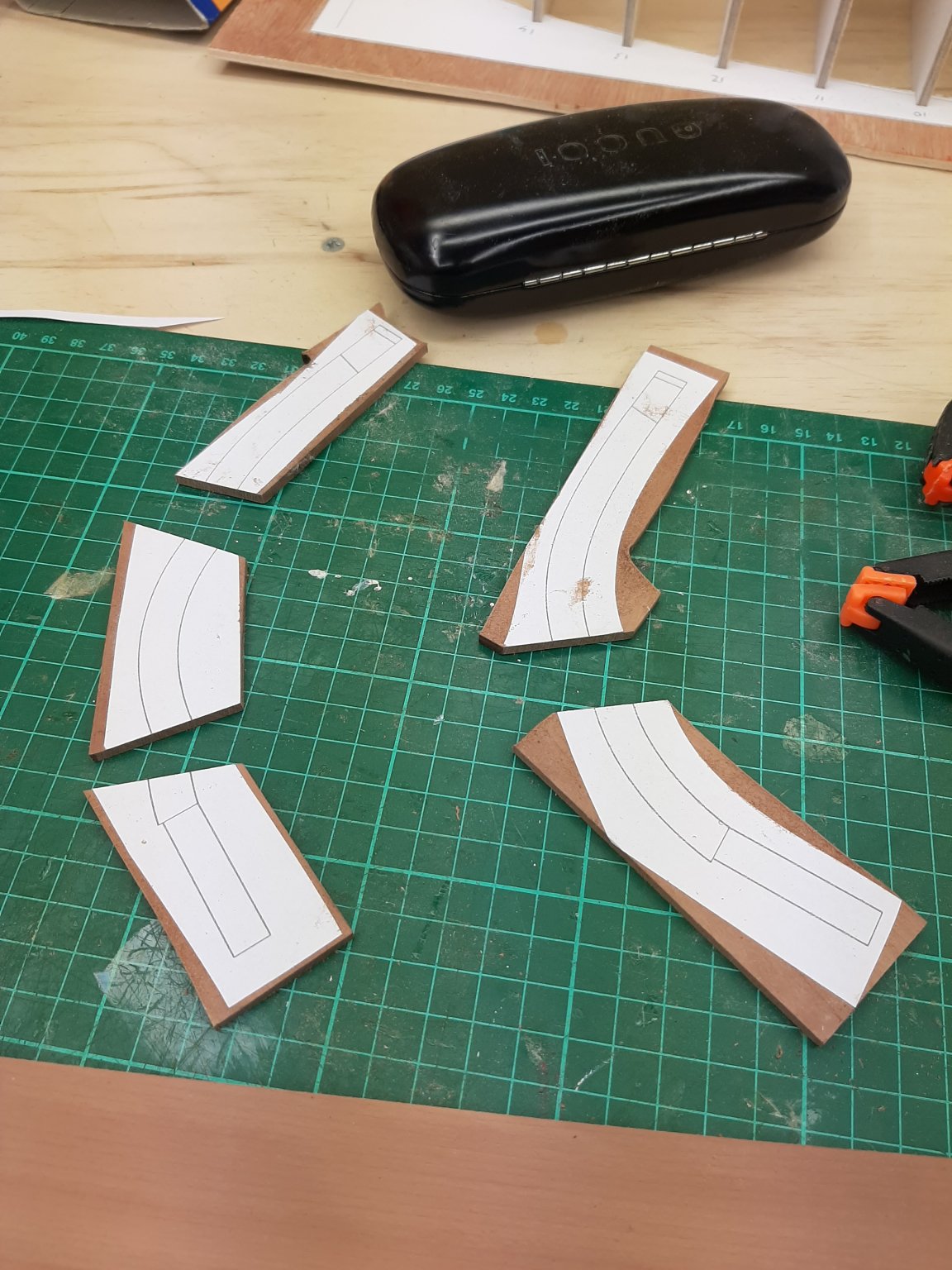
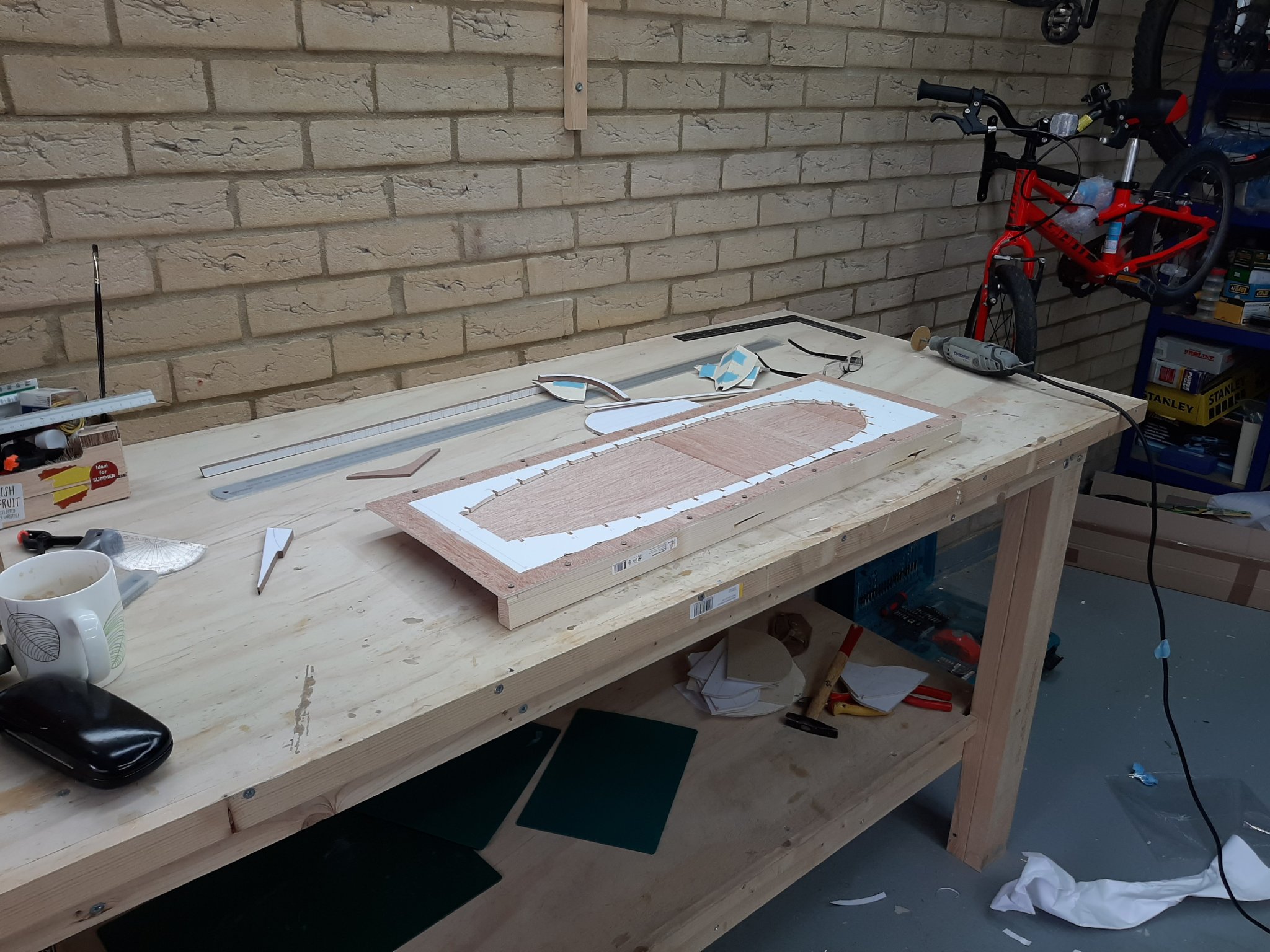
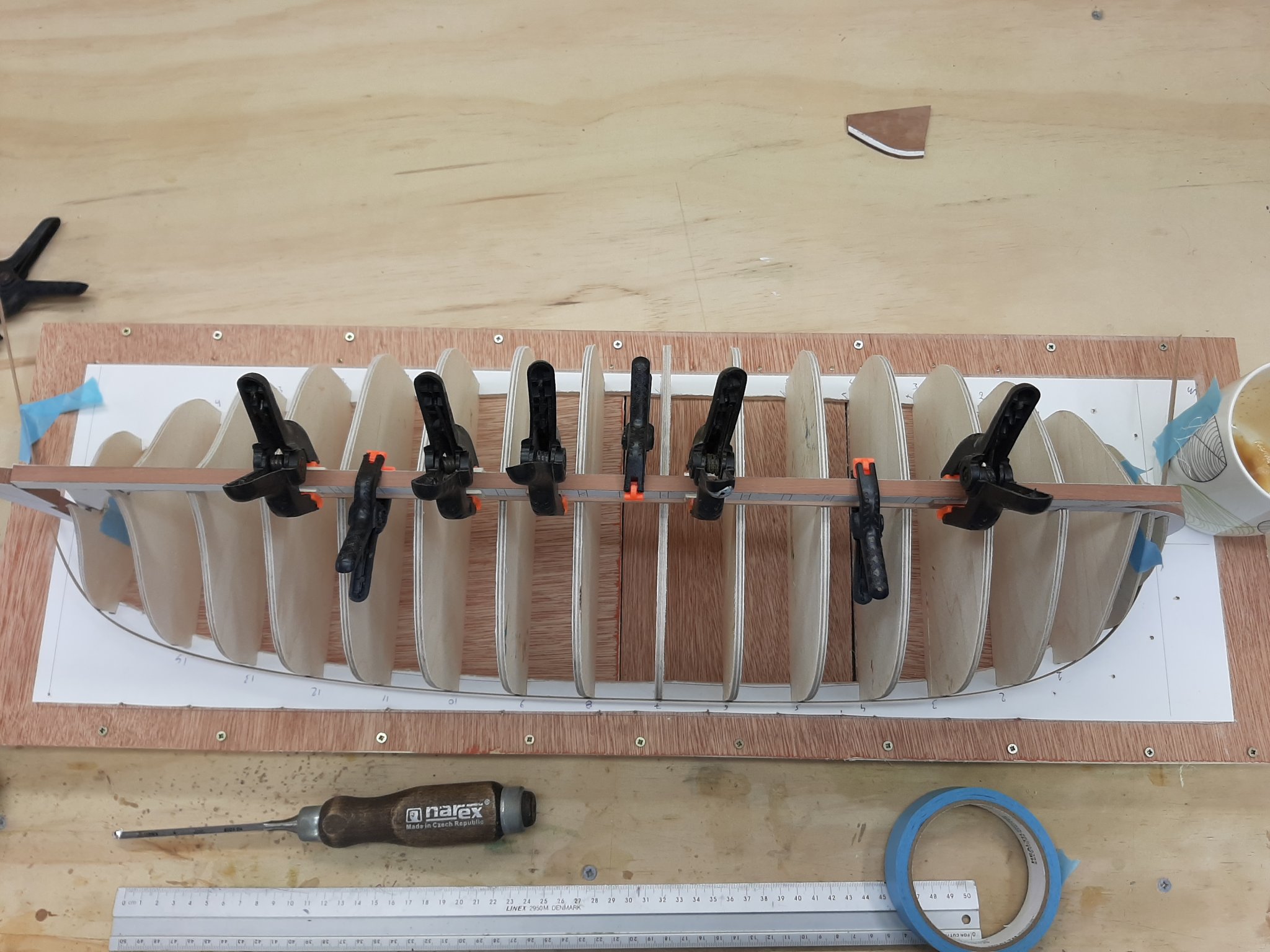
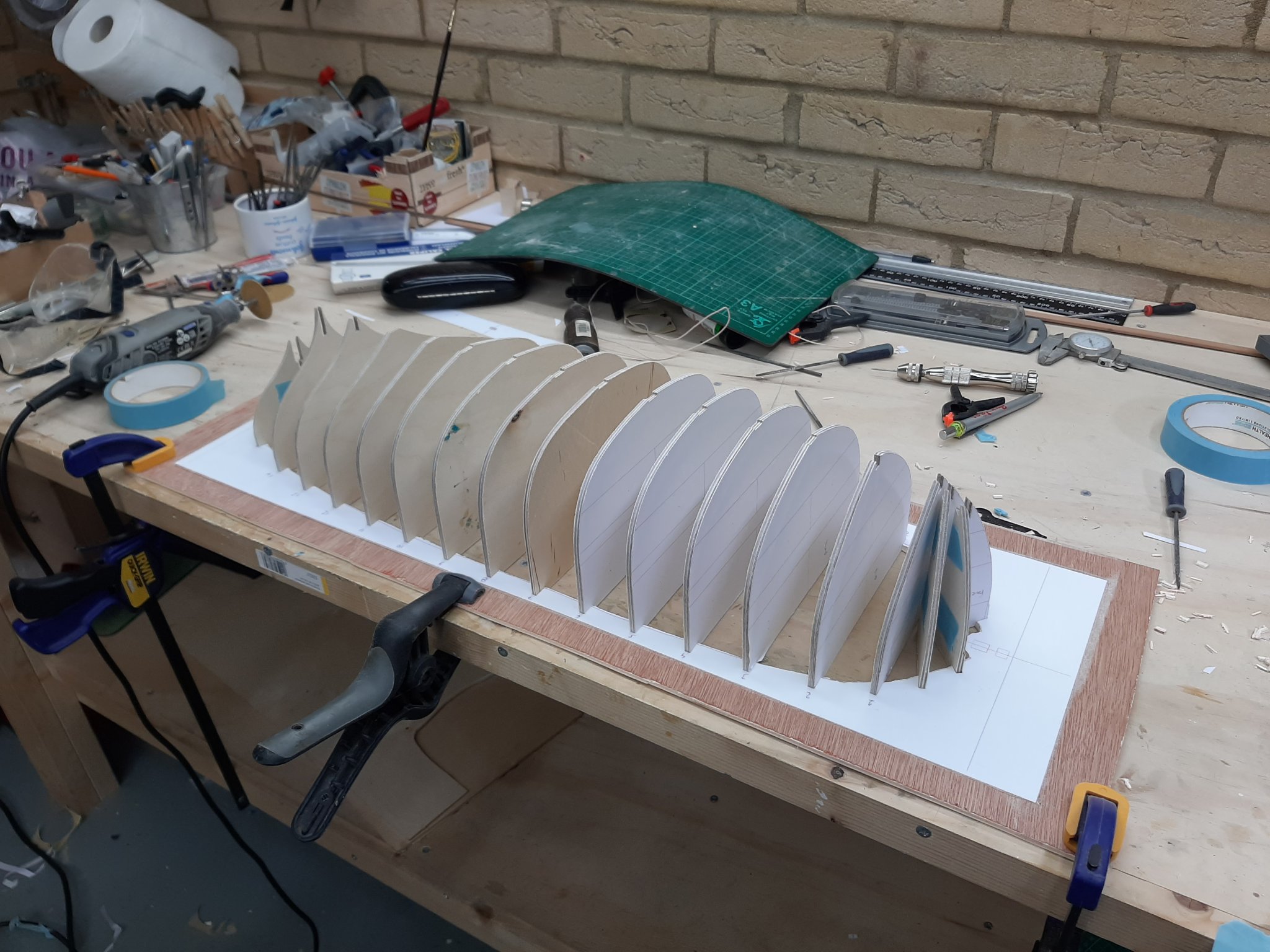
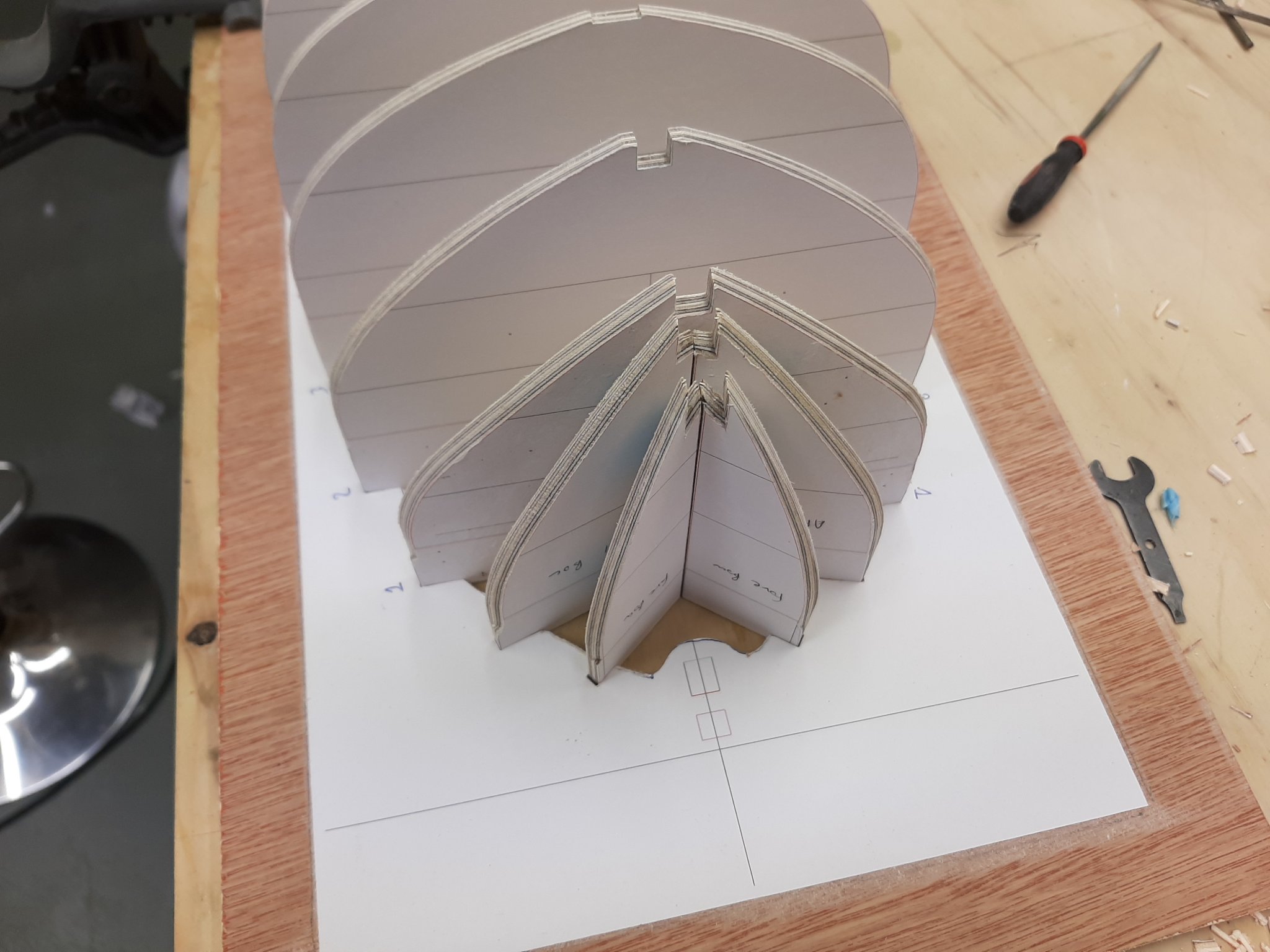
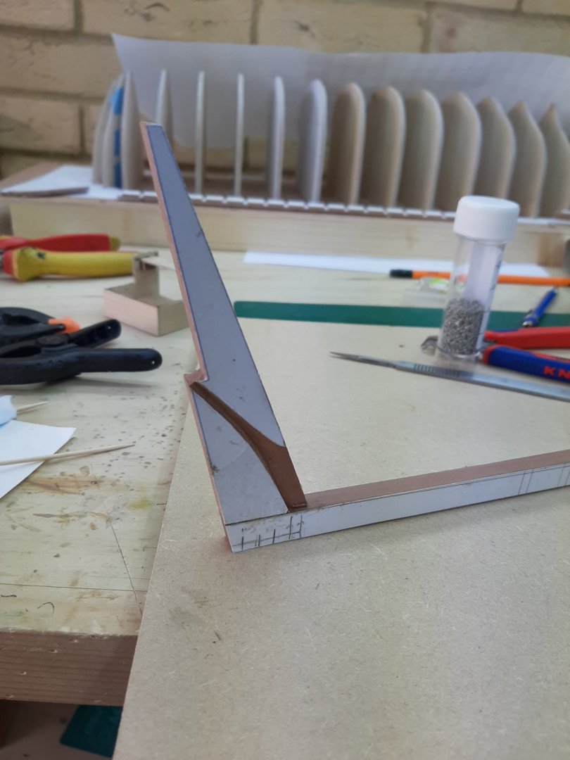
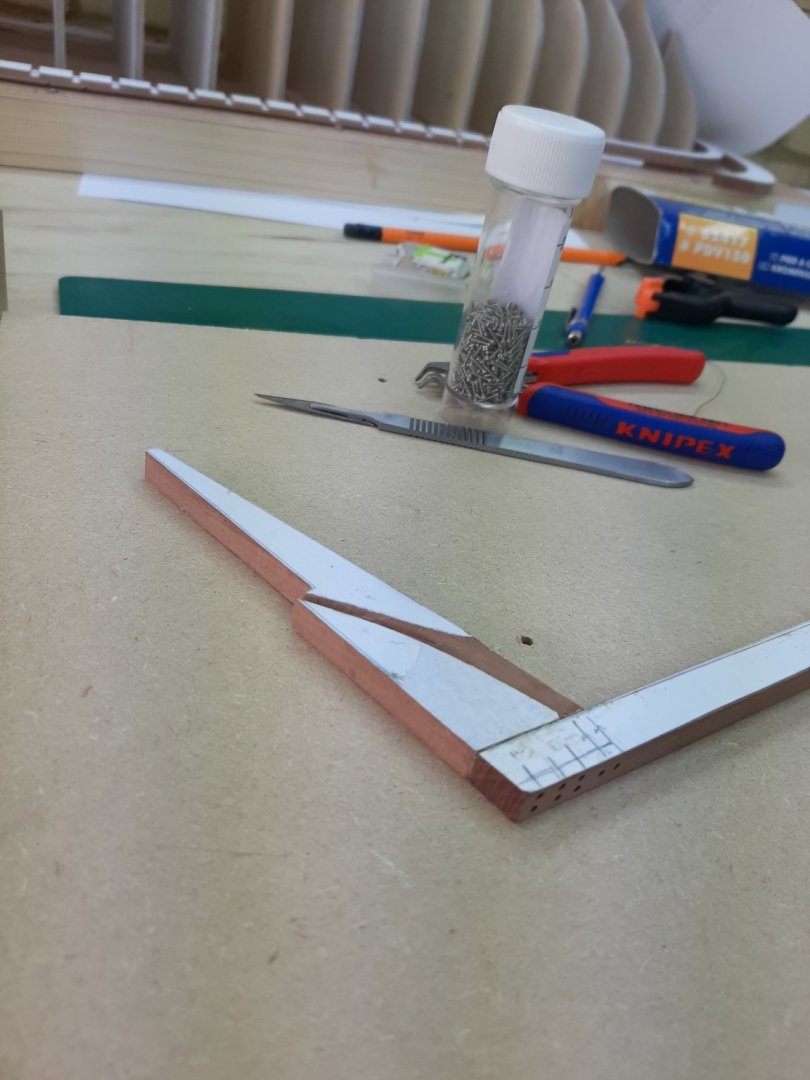
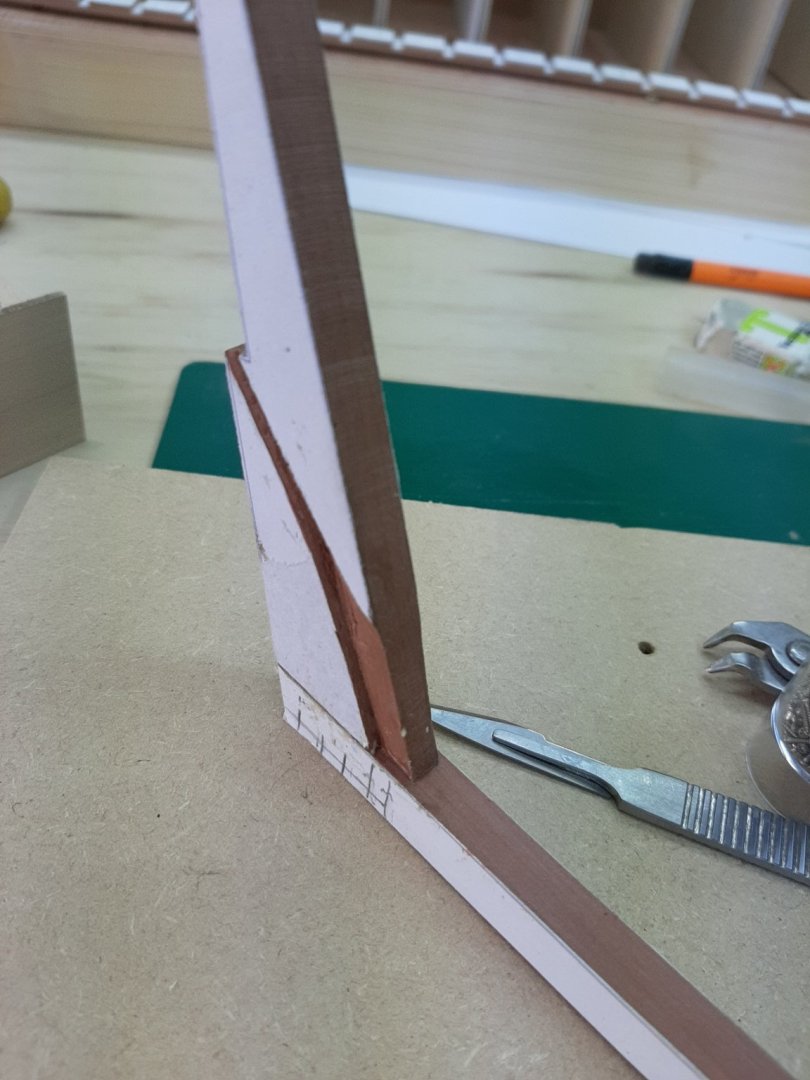
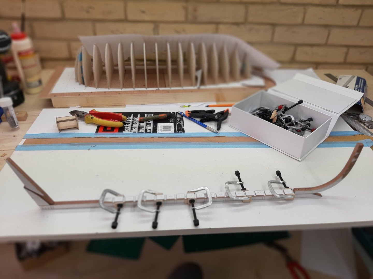
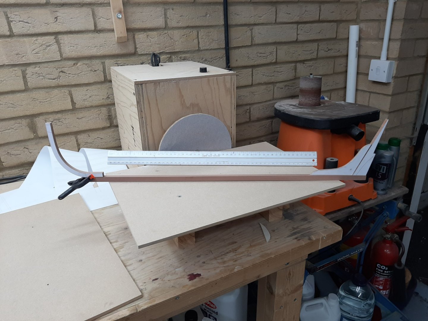
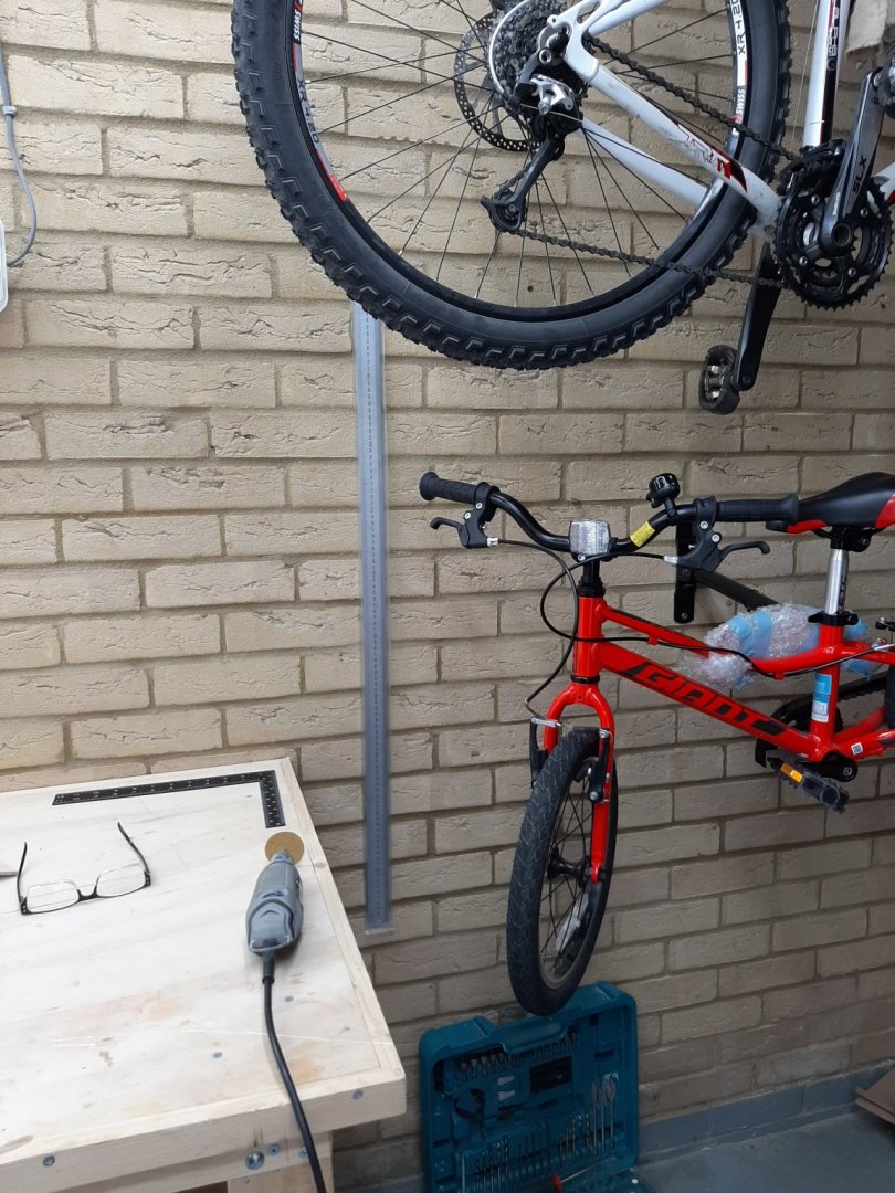
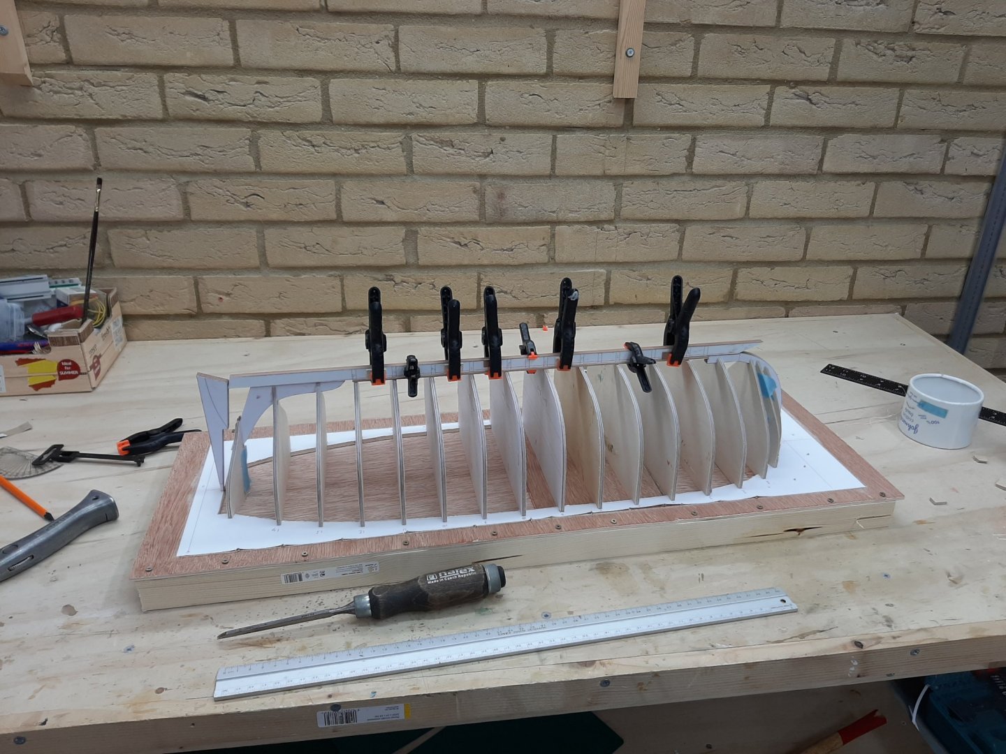
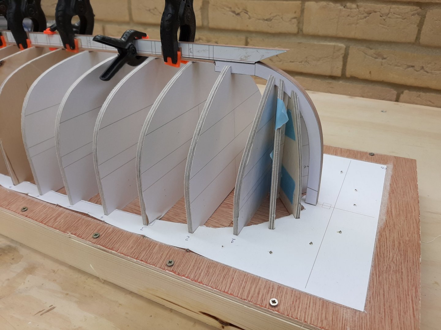
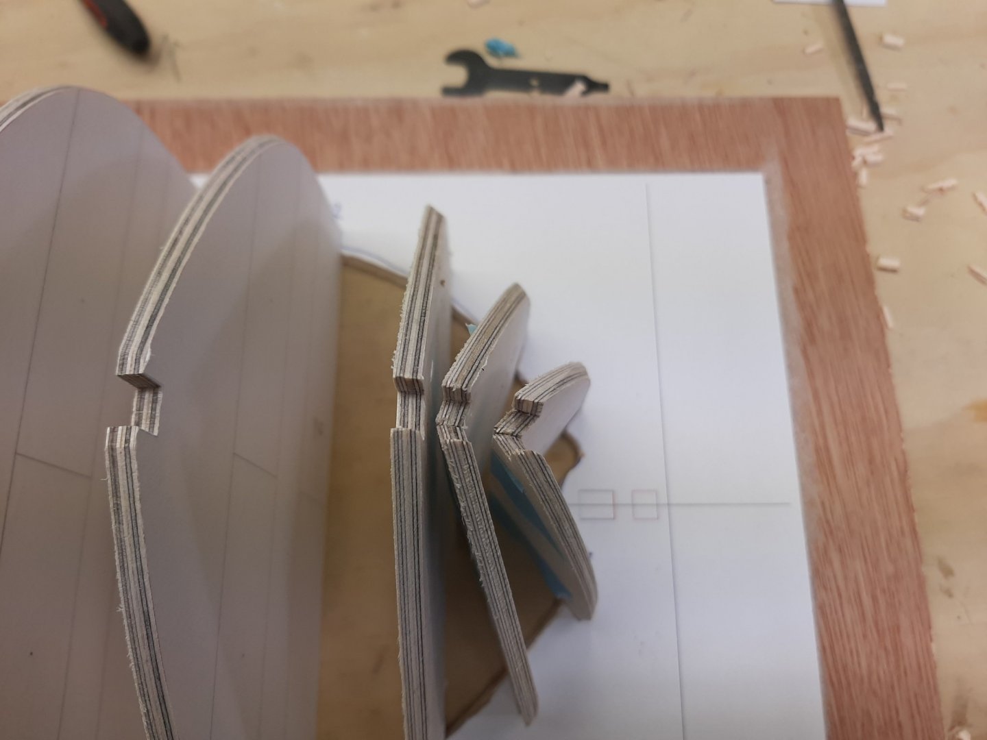
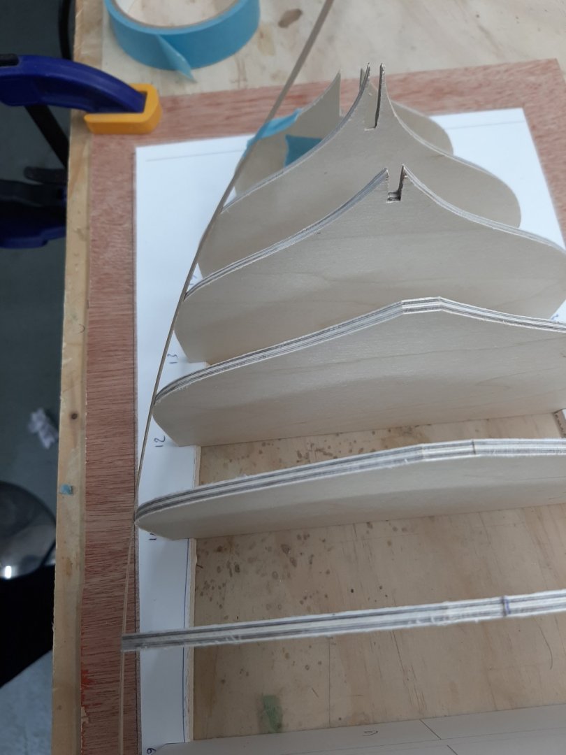
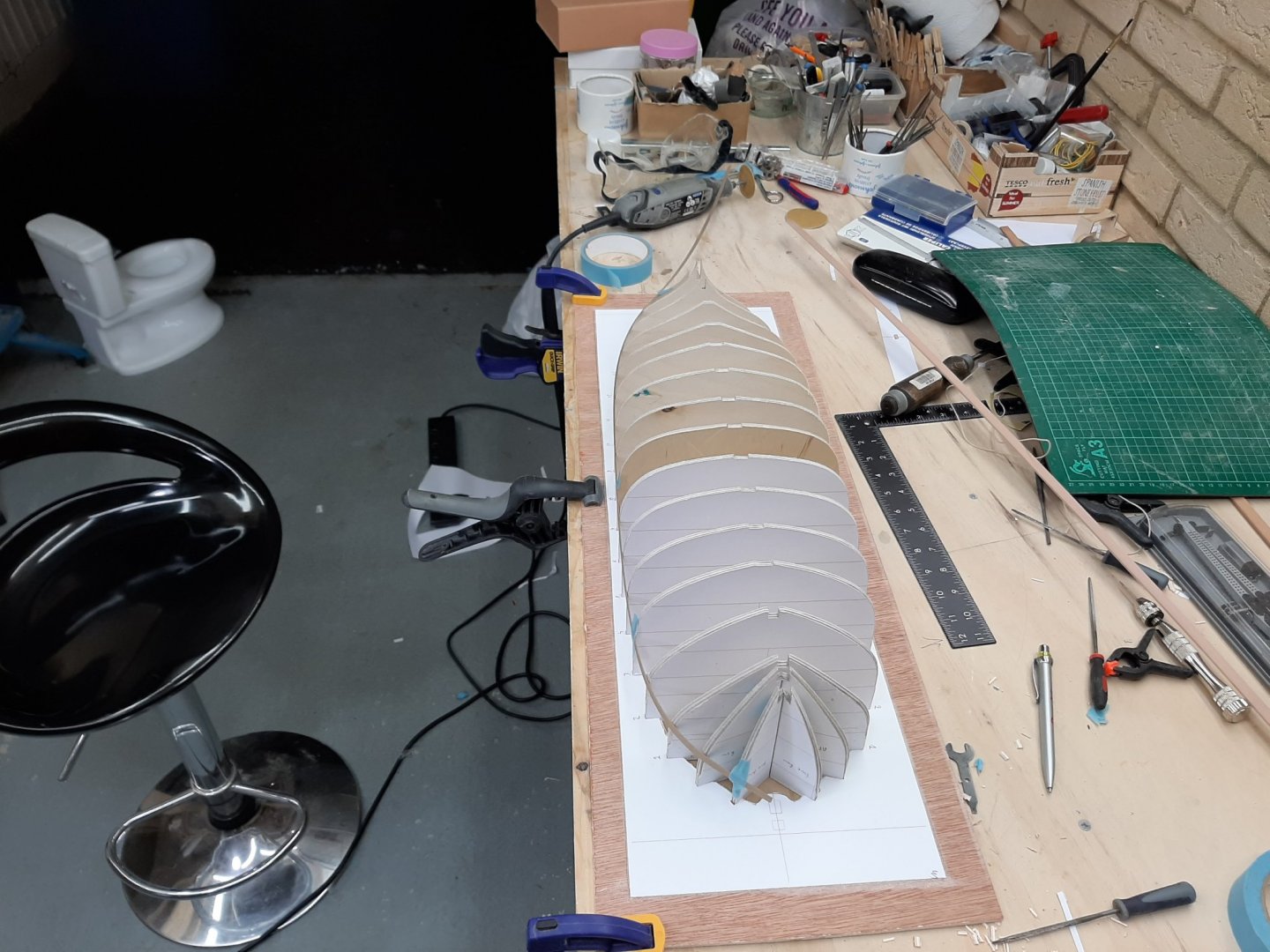
Life went a bit into overdrive but still I managed to do a bit of work. First, I glued the cant half frames with thickened epoxy using the jig to hold them in place. They came out fine but I forgot to take pictures. Then I made the decision to use the solid wood keel and trimmed it to shape-I think it will be fine. I then made the sternpost and the knee and I fiddled a bit with it, to make sure it sits flush with both the keel and sternpost. Then I made the stem. Initially I wanted to laminate it but I decided to make it from overlapping 4 mm thick pieces. Not historically accurate but certainly faster and simpler. Then I worked on the jig. It needs to be completely flat and it seems that the boat will need to be built upside down. We ll see I also made a brilliant purchase, a 1 m steel ruler. I really don't know how I managed so far without it! Lovely thing Then I assembled everything together and of course they don't fit. The frames seem ok but the sternpost and stem don't have any reference points so they are not in the right place and need to be further trimmed. I checked the bevels once more now that most pieces are in place and it really looks ok Then I hit a snug. In the plans the Transon needs to be 5 mm thick but I do not have 5 mm think pear sheets but I do have 4. Only solution to shim the sternpost-I think it will be fine. There are still many other tasks to be completed. Somehow I need to trim and align everything, secure the frames to a near vertical position and cut the rabet on the sternpost and keel-this last job will be difficult. Then the sternpost and knee will need to be securely attached to the keel and the whole thing somehow to the frames. I need to make the transom and fit it to the sternpost squarely. Baby steps...


-
Gary and Brian, many thanks! I am not sure if I ve mentioned it but I am actually thinking for this boat not to use tree nails to hold things together, like I did with the Deben. I d like to try brass wire 0,7 or 0.8 mm, threaded. There will be no glue holding the planks, just the threads. The planks will be initially fastened to the temporary frames with 0.6 or 0.65 mm brass pins, then removed. The biggest problem will be lining up the plank overlap (2.5 mm) and the frame inside (4 mm sided) - for all 2000 or so rivets. I ll do a bit of testing when time permits and will post the results.
-
Hi Gary This is going to be a plank on frame model. These are temporary frames, once erected the planking will go on which will be lapstrake. Then steam bent frames will go on in between the frames, then the frames will be removed and replaced with steam bent ribs. I would like to leave the boat unpainted which means reusing the same holes and this will be one of the many challenges in this build. The planks will be 2 mm thick (and up to 80 cm long...) so should sit nicely on the frames as spaced apart. Not sure if I can pull this off but it will be fun trying. Vaddoc
-
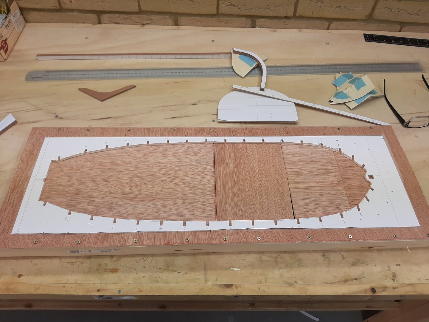
Many thanks to all for your sympathy and comments. Yes, indeed things are now back in order! I re-printed and re-glued the template for the jig, cut away the excess and sanded the notches to size. I fitted the frames and made the final adjustments. All look good and actually I ll use the jig to align and epoxy the half cant frames together. In all honesty, I am not sure how the jig will work to allow also planking of the boat. I think somehow the temporary frames will need to be secured to the keel ot ribands to be set up, however no rogue holes should be allowed. We ll see. The bevels look alright... Next, the wood arrived from Arkowood. Very nice, the colour of the pear is uniform without any light bluish areas. The beech wood is also nice but probably unsteamed as it has a yellow hue instead of pink. I think it does not go as well with pear but I will Tung oil the pear wood so I think it should work in the end. Or not! A couple of the beech sheets are quite warped but we have to accept that with some woods, this can happen. I think they are probably a bit too warped to be used but we shall see Now, I also received long pieces for the keel as well as half pieces with the intention of laminating it. None of the pieces was dead straight and in the end I managed to isolate a segment that was reasonably straight, at least sideways. I then tried to laminate a keel but using PVA. It came out slightly out of alignment sideways. This confirms to me that PVA should not be used for laminating, if I had used epoxy it would have been dead straight. The solid keel I ve cut earlier is better. I think I will give it one more go laminating with epoxy but really, I think the solid keel would be good enough. Off with the girls to Cambridge now before rain sets in BTW, you are all invited to visit the Fisherman's launch log which I hopefully will start later on today. Starting a second scratch build when I have barely any time for one? Well, there is an explanation, all in good time. Best regards Vaddoc


.png.08a6a2eb18d06dcfd25d217292f95f69.png)