

catopower
-
Posts
1,615 -
Joined
-
Last visited
Content Type
Profiles
Forums
Gallery
Events
Posts posted by catopower
-
-
Looks like I will be at the conference after all, representing Ages of Sail in the vendor room. Looking forward to seeing you all there!
Clare
- MEDDO, Ryland Craze and mtaylor
-
 3
3
-
Also, for those scratchbuilders out there, the plans are available as a separate purchase. It is also possible to order P.E. fitting and castings sets specific to the kit. But, the kit has everything and is definitely one of those that make me drool...
Oh, and forgot to add that Ages of Sail should have the plans and kit available. Email or call about the availability of PE and castings sets.
-
-
Also available in the USA from Ages of Sail, which is the North American Distributor for OcCre kits, and MSW sponsor!
- Keith Black, chris watton and mtaylor
-
3
-
Hi Pat,
It's a good question. The answer is really that I can't say for sure. I'm not aware of any archaeological evidence, but that doesn't mean it doesn't exist. Might be in a museum somewhere. Mostly, all I have to go by are modern models and some old paintings. The paintings don't show this level of detail, and I don't know where the knowledge of the model builders comes from. I've seen nothing written about the subject, but my access to the information is extremely limited.
As far as I'm aware, there is nothing for the oars to come "loose" from. The ropes serve to keep the oars in place and double as full-time "retainers".
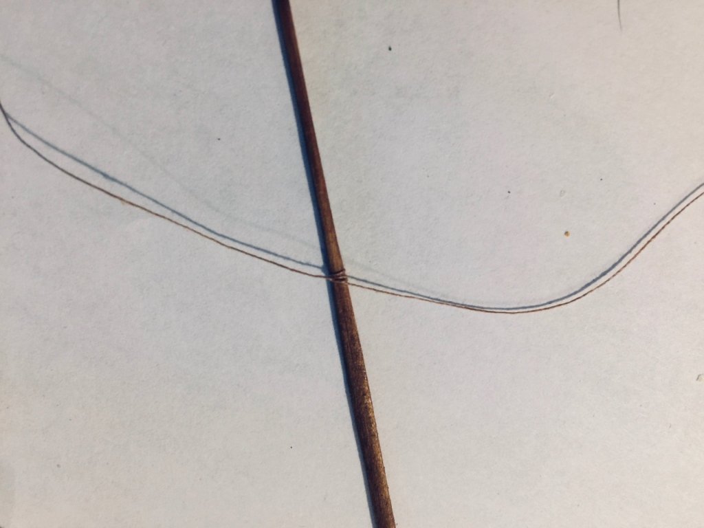
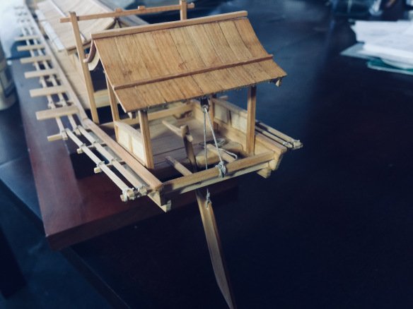
Note that on sculling oars that appear later on, boats do not use any form of rope retainer. The oar has a small hole that fits over a ro-gui, which is a rounded metal knob. The only rope is one that holds the handle of the oar in a proper position for sculling.
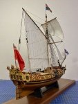
You can see such a rope on the model below. If used correctly, it would also serve to keep the oar from getting away, should it become dislodged and fall overboard.
This is a model of a water taxi, called a chokibune. A similar boat is detailed in Douglas Brooks' book Japanese Wooden Boatbuilding.
-
Thanks everyone for your concern and good wishes!
All is well. My insurance company took good care of me and paid out for the car. I feel sorry for the guy who rear-ended me, as he damaged his own truck as well as my car and my insurance company is going to be wanting to recover their money. Turns out he did have an insurance company, but he didn't have the truck he was driving on his policy. Don't know if it was an error on his part or what.
I lost a reliable, tough little car, and had to go through the process of getting a new one – and it's a process I HATE. But, the insurance company paid out very quickly. Only now, I have car payments. But, I like the car. So, all is well.
Work-wise, I've just been a bit too busy, so decided to try to slow down a bit and to try to make some modeling progress. Took some time out today, as I'm feeling really worn out. But, made a little progress on the trade boat and other things.
You may recall that this boat has one large sail. I don't know if I will mount a sail on it or not. I find it rather interesting how the lowered mast is stowed. I think I have a method for creating the sail, which was made from rice-straw matting, not cloth. But, I will have other opportunities to make that, and it would probably be simpler and more realistic at a larger scale.
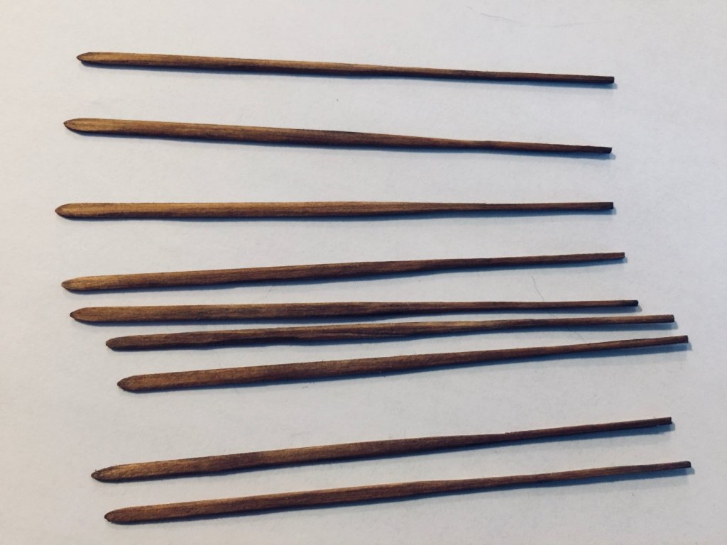
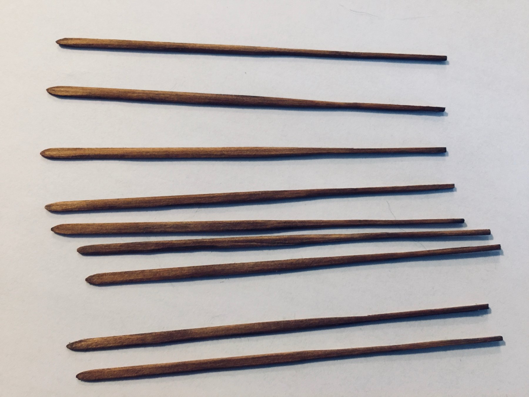
In any case, I also have the full set of oars I made. I've decided that even though the museum models I've seen show the boat equipped for sculling, that my interpretation of early scroll paintings suggest they were rowed and not sculled. Also, I started to thinking about the side-to-side motion involved in sculling, and I see only rope bindings on these oars in all cases (museum models).
I can't see how rope bindings would be able to take the amount of side-to-side pressure without loosing very quickly. If rowed, the binding would simply be to hold the oar and keep it from slipping. All the force of propulsion from the oars are taken by the beam extensions of the ship.
So the next issue was how these would tie into place. Nothing too special there, except that you can't simply tie it the oar to the beam, as you'd have a hard time moving it. You need to tie a rope securely around the oar and then that rope needs to be tied to the beam. Does this difference make sense? There needs to be some freedom of movement for the oar, so the rope itself becomes something of a pivot.
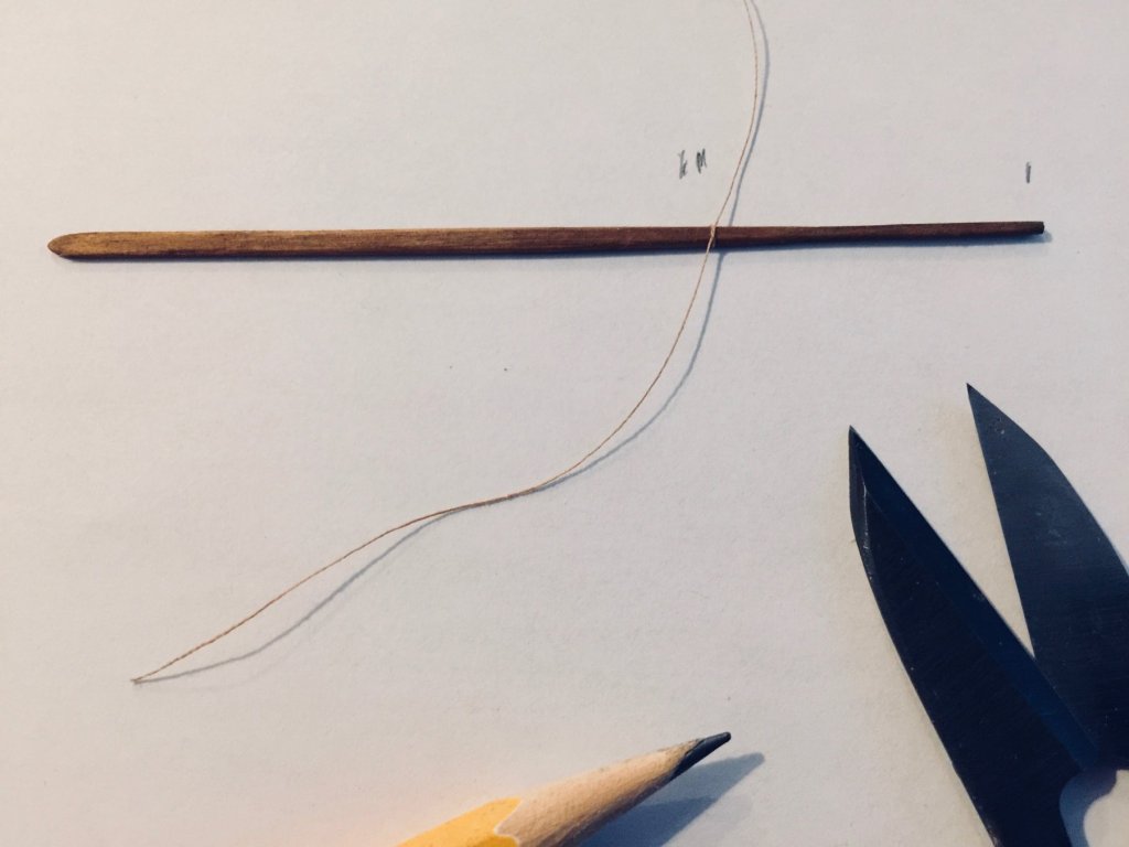
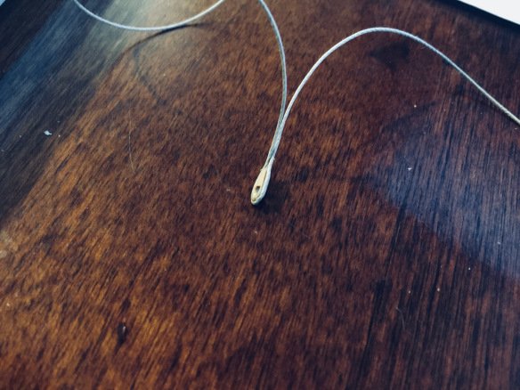
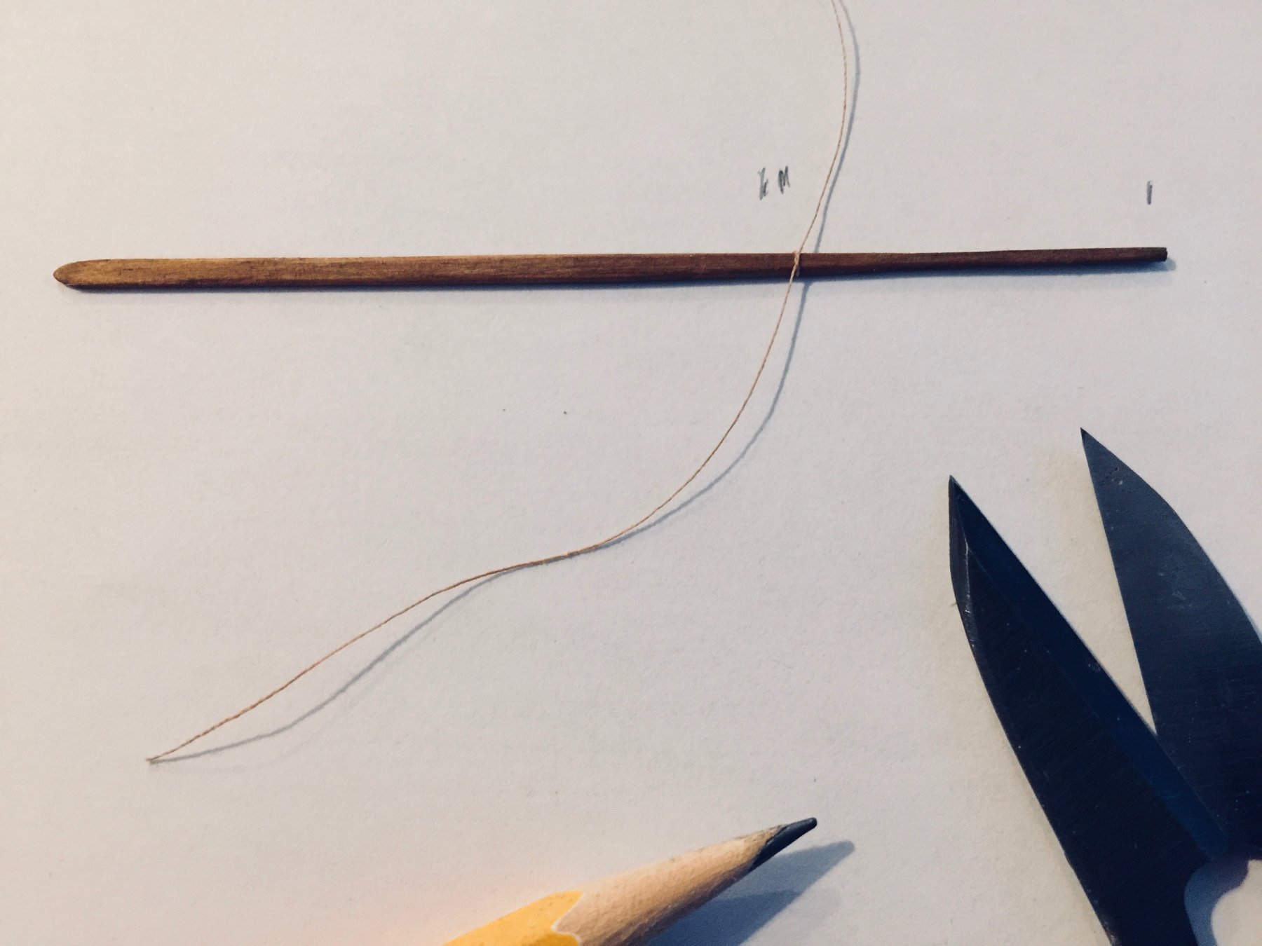
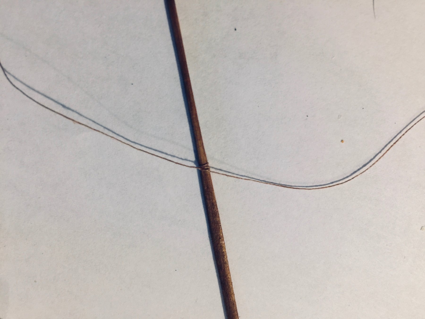
So, I started by tying a length of line around each rope at the pivot point. I used pencil marks for measurement. I didn't feel this needed to be exact. There is an extra pencil mark, as I realized I wanted the pivot point just a little higher up on the handle. Thread cutter and pencil included for size reference.
After I tied all of the oars like this, I realized I needed more of a lashing, so I wrapped the thread around the oar and tied a second knot.
Tying the rope then onto the model, I kept the knot-side against the beam. I can't quite explain the final wrapping, as I kind of figured it out as I went. Something like wrapping both ends under the beam, over the top a couple times, making sure to stay on the opposite sides of the oar, then tying a final knot around the rope in between the oar and the beam. This turned out to be as challenging as rigging blocks on a square rigger.

Another difference between my model and modern museum models and their sculling oars is that sculling oars have a handle near the end of the oar and a line tied down to the rail or beam wraps over that to help hold the oar in place while sculling. Such lines seemed to have no purpose with this type of oar, so I didn't include them.
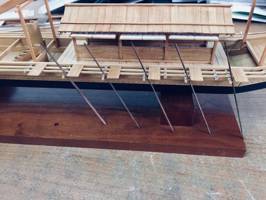
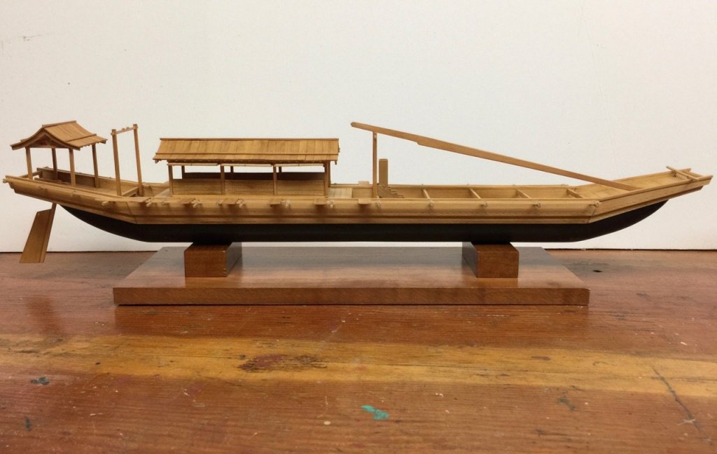
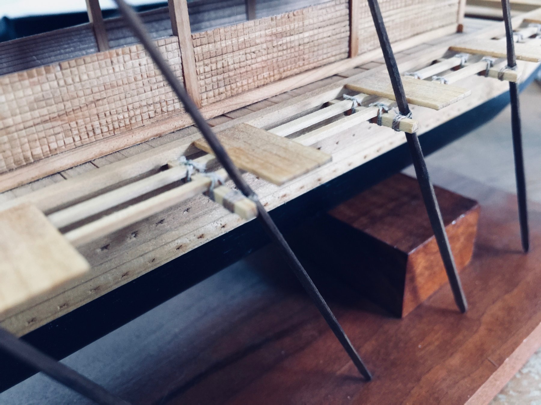
In this side view you can see how the oars look once they're all on the model, though I still have to add them onto the other side. I made the base just a tad too short, causing the aft-most oar to hang down just a little too much.
-
I've always thought this was a really nice looking kit of a nice looking boat. Well done with the kit review, James.
I might also point out that this kit is also available from Ages of Sail, which is also an MSW sponsor.
Clare
-
Thanks friends! Fortunately, I was uninjured, but my car was totaled and the other person was effectively uninsured, so it took a while to resolve. Then, after having to work more hours, dealing with the car rentals, getting paid, finding a new car, dealing with new payments, etc., it took my remaining free time.
I still am working more hours, so it has affected my ship modeling time, but at least the other issues are behind me. Mostly...
Clare
- Bob Legge, Landlubber Mike, mtaylor and 3 others
-
6
-
Hi All,
Finally a post!
As if my work wasn't coming along slowly enough, a car accident and heavier work load managed to bring my ship modeling of all types to a standstill.
After nearly two months of making no progress on anything, I finally found myself in a position to move forward again on the Umibune. I didn't managed to figure out too much regarding the making of scale figures for the model, but I did finish tying the bindings on the rails. I also decided on how I wanted to finish the aft deckhouse, or yakata.
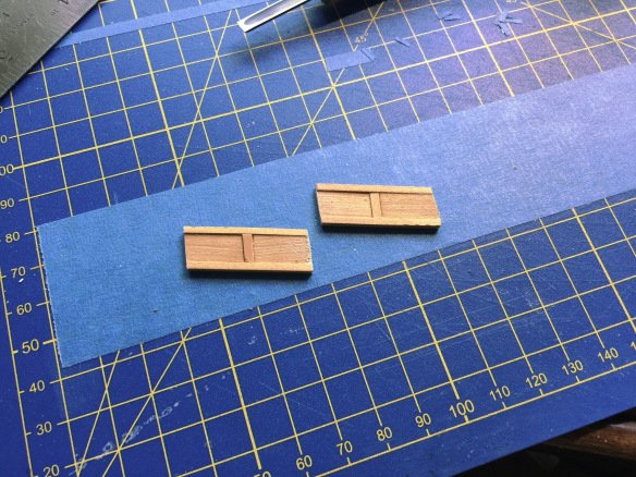
I basically returned to the idea of installing only lower panels on the sides of the structure. There seem to be a multitude of ways that artists and model makers have interpreted this design, so I just went with something I recall seeing in a painting. Is it accurate? There really doesn't appear to be any way to know for sure. But, it seems reasonable. In the photos below, you can see the panels before installation, as well as how they look in place on the model. I originally built these slightly oversized, allowing me to adjust them to fit.
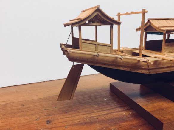
As you can see from the photos, I also attached the rudder. The rudder on larger Japanese boats are fit through a hole in the back edge of a heavy beam at the stern. The Japanese did not use gudgeon straps and pintles to hold the rudder in place, but instead, rudders were held up by a rope lifting system, like Chinese boats, which allowed the rudder to be raised or lowered as needed. The hole in the large beam provided the necessary lateral support.
The lifting rope is attached to a hole in the top of the rudder blade and runs through a block, which is attached to the aft-most roof beam. The design of the block was not described anywhere, so I based it on a block that appeared in Woody Joe's Higakikaisen kit. This is a teardrop shaped block that apparently contains no wheel, unlike a modern-style block.
I was motivated to use this based on a comment that was made to me while visiting the Hacchoro fishing boats of Yaizu in 2016. While showing me some of the features of the Hacchoro,
Mr. Hiroyuki Kobayashi, one of the people who are responsible for the Hacchoro boats, told me that while the Hacchoro replicas use a standard wooden blocks in their sail gear, the Japanese didn't originally have such blocks.
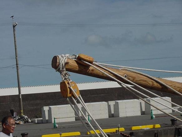
Modern blocks on the modern Hacchoro replica.
He didn't elaborate, but seeing the wheel-less blocks on the Higakikaisen model suggested to me that this was the design that the Japanese originally used and is what Mr. Kobayashi was referring to. Unfortunately, I can't find any photos of that type of block, but here's the one that I made.
This type of block would most certainly have too much friction with the rope passing through it to be very efficient. But, it's very possible that its function is more to help support the rudder than to lift it up. Possibly, a few strong sailors would physically haul up on the rudder and tiller as someone hauled on the rope to take up slack and to help support the rudder's weight until the rope was tied off to beam at the stern.
In any case, I glued the stropping rope around the block and siezed it into place. The ends of the rope were simply run over the top of the beam and tied off underneath a crossbeam. I have no idea how the original was attached. Probably just passed around the beam, the way a block is fastened around the yard arm on a Western sailing ship.
The rudder was put into place with a rope seized through the hole in the rudder blade and rigged. To help hold the rudder in place, as it's too light to simply hang from the support rope, a hole was drilled through the rudder post and into the great beam and a pin pass through. This allowed me to keep the lifting rope taught, while keeping the rudder nicely in position.
More on oars and the very unusual anchors next time.
Clare
-
-
-
Hello Toni,
I know some people that will be very happy to hear about this change. Thanks for the announcement!
Clare
- thibaultron, Canute and mtaylor
-
3
-
On 8/29/2018 at 9:12 AM, andante said:
Hello Clare, found your temple site by chance and instantly ordered a pack from Zootoyz. Precise laser cutting and very addictive. You did it beautifully.
Architecture model building can be very relaxing. Years ago I assembled a Lego architecture set, the iconic Villa Savoye by Corbusier and enjoyed every moment of it. Lots of round and transparent elements.
Domo arigato, Olavi
Hello Olavi,
Sorry I didn't see your post before. I hope you got your shrine model and have fun and success building it! They have castles, temples, and shrines, but I like this one in particular, because it is such an old style architecture. I also like that it has a little landscaping, so it is about the sacred space and not just the building itself.
Gambatte kudasai!
Clare
-
LH, I don't know how lighting will affect the aesthetics of the room, given that it's open on both ends, has panels that open up the sides and that the ship can be oriented in any direction with respect to the sun. But, I do agree that the full-width across the entrances is somehow more pleasing.
As you point out, this does have to be balanced out against other aesthetics, including the odd shape for a 6-tatami room.
The last option I posted actually fixes the issue of both wanting full-width mats at the entrances, plus elimination of the four-corner intersecting point, which, to my understanding, is considered bad luck for a room. I don't consider the arrangement ideal, but it might be the most acceptable. When I built Woody Joe's Yakatabune kit, it had a 4-tatami room, which had much nicer proportions, and much easier to decide upon. That one, I arranged in a layout |=|.
Of course, in the case of this trade boat, there's nothing that says it would have even had tatami mats in the cabin, so this is all presumption. But, it would make sense to me, since the only passengers on a large trade boat like this were probably aristocrats.
Anyway, the mats are just that. They are complete removable and can be rearranged. So, if someone didn't like an arrangement, I'm sure they could 'fix' it as needed.
Clare
- Canute, Landrotten Highlander, cog and 2 others
-
5
-
Oh, and actually this may be a 3rd possibility:
3. ||=||
By the way, thanks to LH and Carl for mentioning this book. You can still get it on Amazon in paperback and kindle form. I just ordered a copy. I'm sure I'll find it useful.
-
Thanks for your posts LH.
I knew about the kan, but have only run across the measurement in use once and never read anything on its basis in architecture. Very interesting stuff! Does the book say how far back these rules went? It would be easy to apply it to the Edo period, 1600 - 1863, but this would be Kamakura period, 1185-1333.
The idea of the "floating" sizes of tatami mats is very helpful in this case. The width of the large yakata would allow for one full 5.8 x 2.9 shaku tatami mat to fit lengthwise across it. I don't know that my structure is perfectly proportioned, but yes, it should fit a 6 tatami layout.
Now, I have to think about the configuration, and this brings us to the essence of wabi-sabi in the layout of the mats. I was originally considering the one you listed as the 3rd configuration, but 4-corner joints are to be avoided. In fact regular grid patterns are to be avoided too. On a layout to fit this kind of building, I think there are only two options:
1. =||=
2. =|=|
I've only seen the 2nd one listed as a suggestion for this size and shape of space. Well, something more to think about.
Clare
-
-
Yes, there were three different standards for Tatami mat sizes that I'm aware of, and I guess they were pretty regional. You may very well be correct about being based on the height of a man, though I've never read anything specifically about that.
Shaku, however, is a simple unit measure almost exactly equal to 1 foot. There are other old units however, and one of them may be based on the approximate height of a man at the time. I ran across something like this, but don't recall the specifics.
Clare
-
Thanks Steve, I appreciate that. I'd always figured on some kind of mounting blocks, so I had built the hull with brass tubing glued in for mounting pins. The inside diameter is a nice snug fit for the brass rod that I fit into those blocks.
I made one attempt at making the walls for the sides of the aft structure, but am not very satisfied with them, so I'll make another.
I'm now thinking that I should probably have a tatami-style mat for the floors of the structures. During the Edo period from the 1600's to about the 1860's, I know that Tatami mats were standardized sizes. But I don't know how far back that goes, so I'm looking into that now.
Clare
-
Minor update that I thought I'd go ahead and report.
It's finally time to create a mounting display for it. I wanted something simple, given the unusual detail and shape of the model, so I went with a block-like base made from cherry wood.
This mounting will allow the model to sit high enough for me to rig the rudder and the oars, though I'll wait until I finish the last of the cabin structure details. I also discovered that there are a couple beams that don't have ties on them, so I'll finish those up next.
Most of my ship modeling delays have been because I've been trying to make/modify figures for my models. I have mostly failures, but I'm learning and working towards having maybe 3 or 4 figures for this model. I just have to double-check on the clothing from 1300 A.D. Japan.
Clare
-
Hi James. Thanks for posting these reviews.
These look like very nice kits, and it was very nice of them to send you kits to review for free.
But, I'm a bit surprised to see your comment that none of the kits have cant frames, when I clearly see cant frames in the plan top-view and in some of the model images. Am I mis-reading something?
20 hours ago, James H said:Note that whilst these kits are POF, there are some simplifications in their construction. For example, these models don’t have cant frames.
Clare
-
Forunately, it's supposed to be a fairly easy build, and I'll bet you can figure out the instructions with just the Google Translate app.
For the benefit of others, here's a photo of this kit from the box art, in case you don't know anything about this kit.
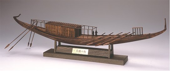
It's a 1/72-scale model of a boat that was buried along with various treasures of King Khufu (Cheops).
Here's a photo of the kit built by Don Dressel of the SMA, Fullerton, posted with his permission...
This is a really nice looking kit and Don said he really enjoyed building it. You can find it easily through the Japanese online hobby dealer Zootoyz.jp.
Okay, now I'm jealous Mark. I want to build this kit too!
Clare
-
Hi Mark,
Congrats on jumping in on that kit. I think you'll really like it.
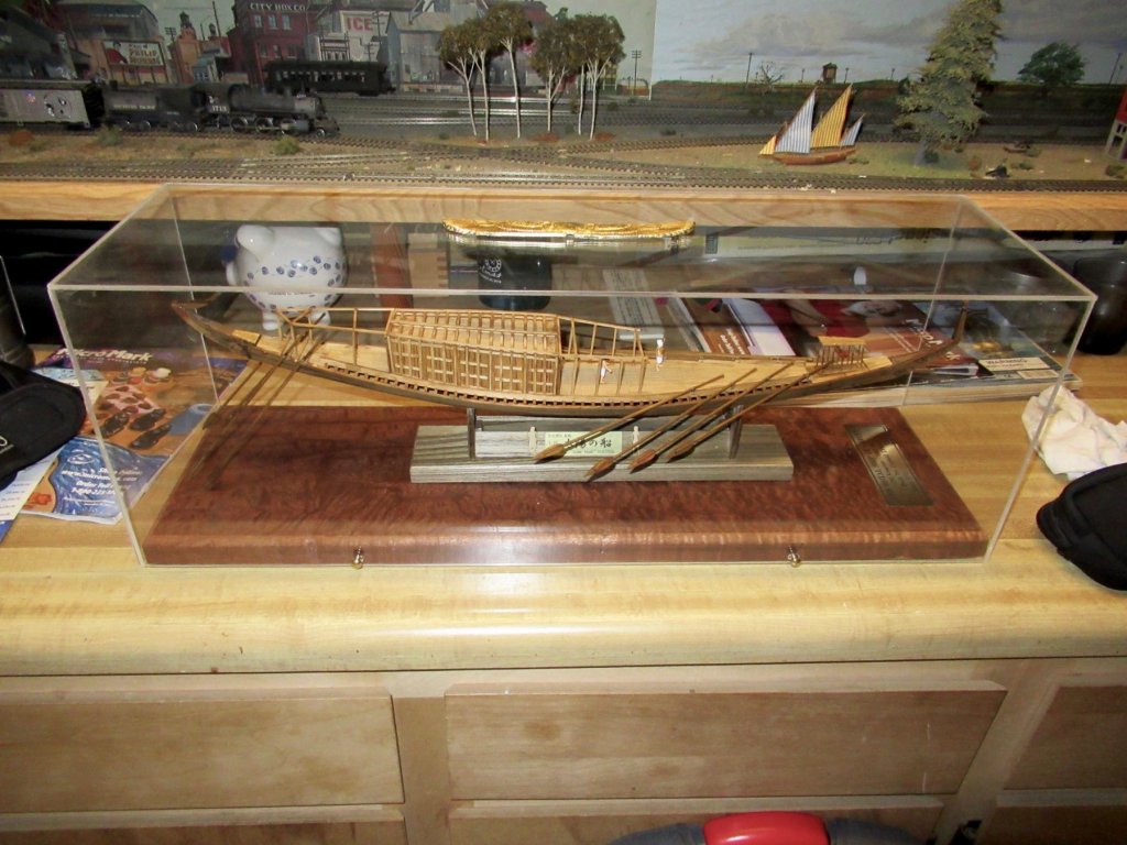
I did hear back from the Khufu ship builder I mentioned, and he commented that he really enjoyed the kit. He had some problems understanding the Japanese instructions until he found a translator app for his iPad. I have Google Translate on my iPhone and that seems to work pretty well too. He's planning on bringing it to the NRG conference this Fall. That doesn't help you any, but I did get a photo from him. I didn't get his permission to post it, but I can PM a copy to you so you can see a built model for yourself.
Best Regards,
Clare
-
Hi Mark, I have not, but have been thinking about it.
I know someone in the SMA club down in Southern California who started one last year. I'll ask him about it.
It looks like a very interesting model and if you buy from the new Zootoyz site for wooden kits, Morikawa-san has a sale going on there that ends in 4 days, on 6/24. Well, that is, the sale prices are good through the end of the 24th. They're a day ahead of us, so maybe make that 6/23!
By the way, it's my understanding that he just created an MSW account, so maybe he'll start chiming in direction on the Woody Joe stuff!
Clare


Newsworthy updates from Chris Watton
in Traders, Dealers, Buying or Selling anything? - Discuss New Products and Ship Model Goodies here as well!!
Posted
Chris,
I suspect that anything you decide to do as a first subject will be a hot seller, so have at it! We're all waiting excitedly for it.
Clare