

catopower
-
Posts
1,774 -
Joined
-
Last visited
Content Type
Profiles
Forums
Gallery
Events
Posts posted by catopower
-
-
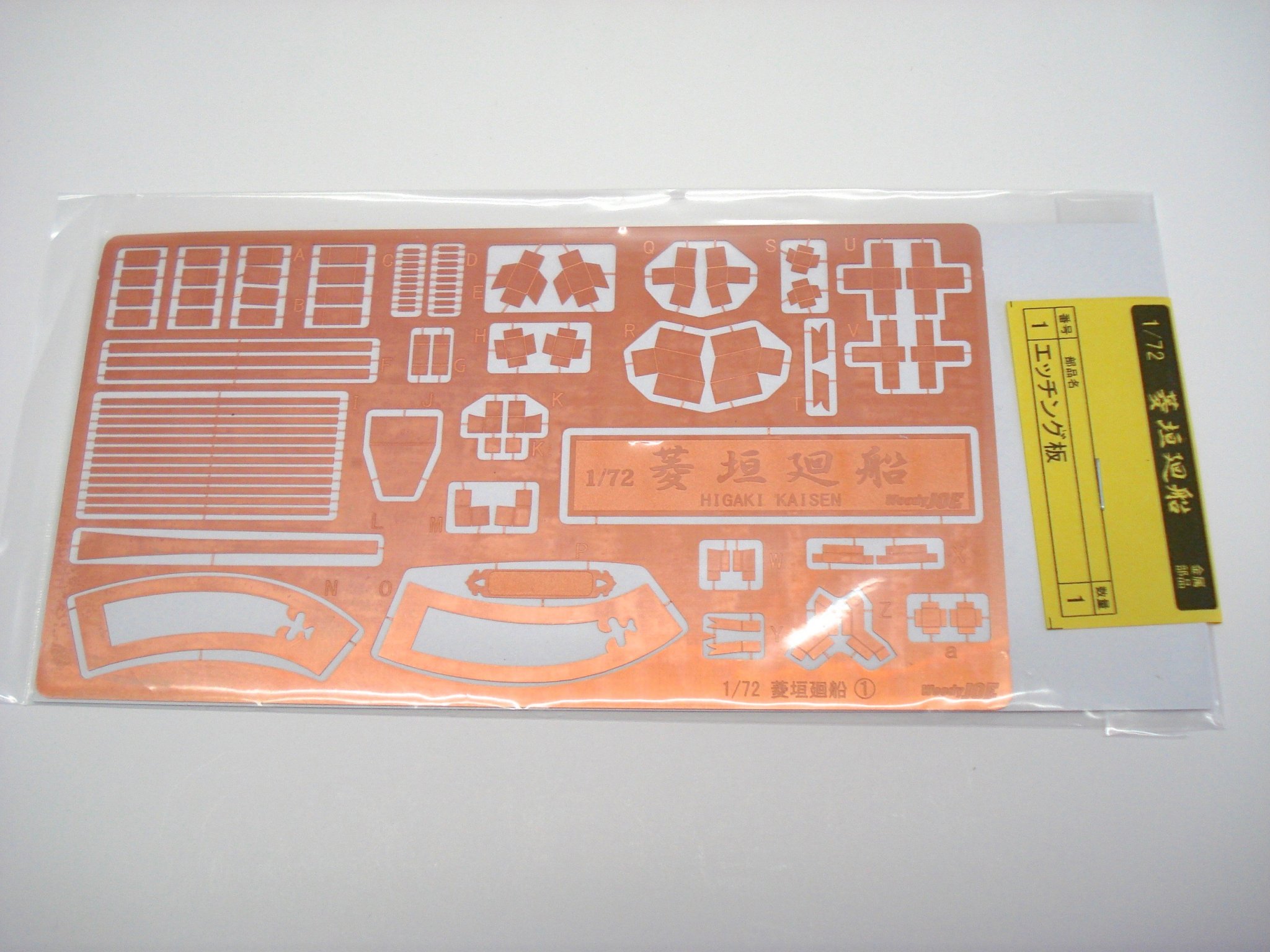
At this point, it's time to look at the copper coverings on the beams and mortises, etc.
The Woody Joe kit provides a photo-etched copper sheet, which must be some kind of copper alloy, as it doesn't really tarnish. Below is a photo of the one from the Higaki Kaisen kit, which is very similar.
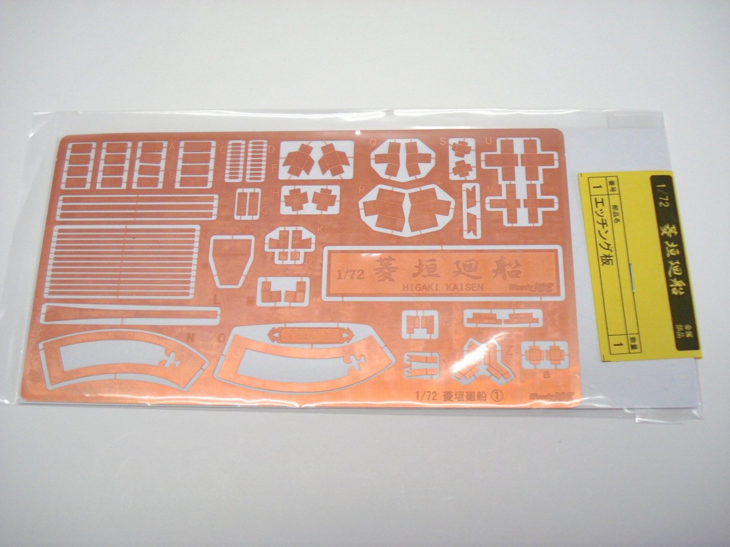
These look fine, but the metal is very bright. As you can see from the photos of the Hakusanmaru, the copper is well tarnished. It's probably very green on the ships on the ocean, but I wanted to simulate simple tarnished copper.
I considered using thin copper, which is readily available on the Internet, but thought I'd try something different using a machine that I made use of to solve a recent model dilemma.
In that case, I needed to make a very regular decorative pattern. I won't go into a lot of detail on that, but here is a photo of what I was able to accomplish.
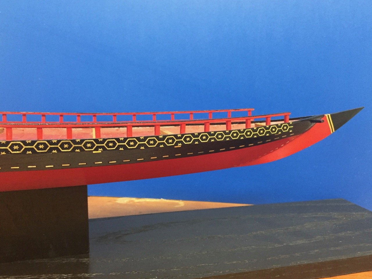
These are photos of an in-progress model of Edo period Kobaya, or small, fast ship that belong to the Shōgun.
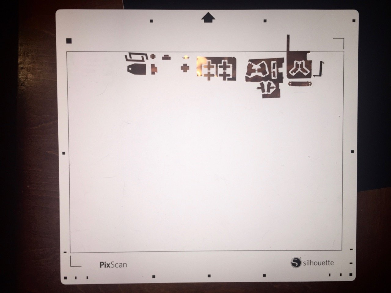
The decorations were made using a Silhouette Cameo 3 vinyl cutter – the poor man's laser cutter. The machine is pretty much just a computer plotter (remember those?) with a knife blade in place of a pen. The device connects to any computer, which controls it much like a printer. Included software allowed me to create the designs and to control the cuts.
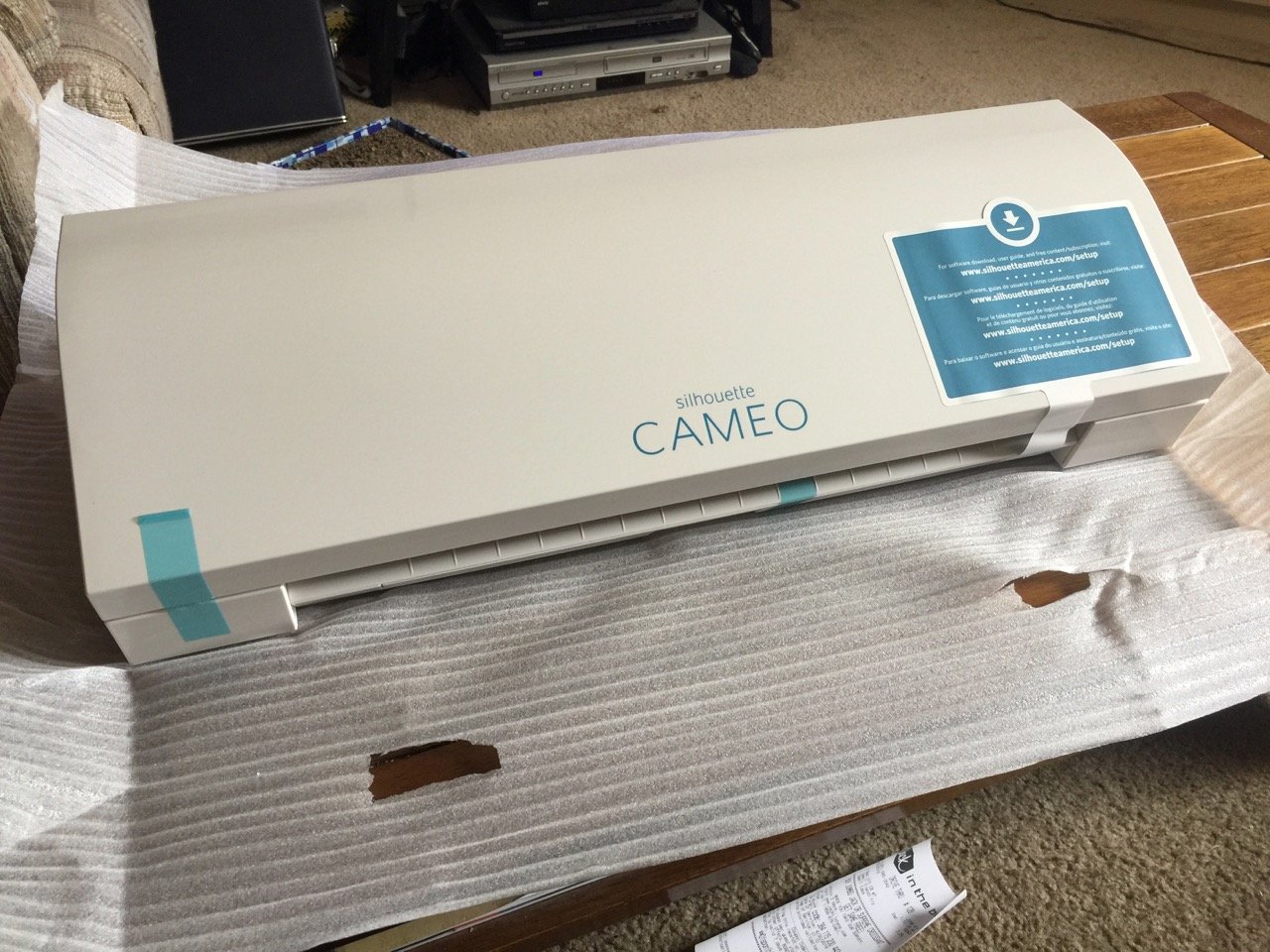
The above photo was taken during unpacking. I got this earlier this year, specifically for solving my decoration issues with that model. Since then, I've found a number of used for it.
For the Kitamaebune, I tried out a feature of this unit, which allows me to take a photo of a pattern I want to cut out, and to import it, process it, and create the pattern in permanent, adhesive backed vinyl. The process requires the use of a special cutting mat which is created with registration marks.
Unfortunately, I don't have any photos of the intermediate steps. But, the cut vinyl is then applied to the model using a transfer material, which is basically adhesive backed, clear plastic. The cut vinyl will stick to it, allowing you to apply the vinyl to the model, after which the transfer "paper" is peeled off.
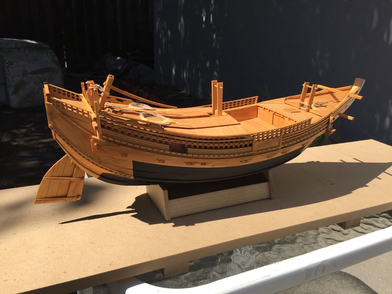
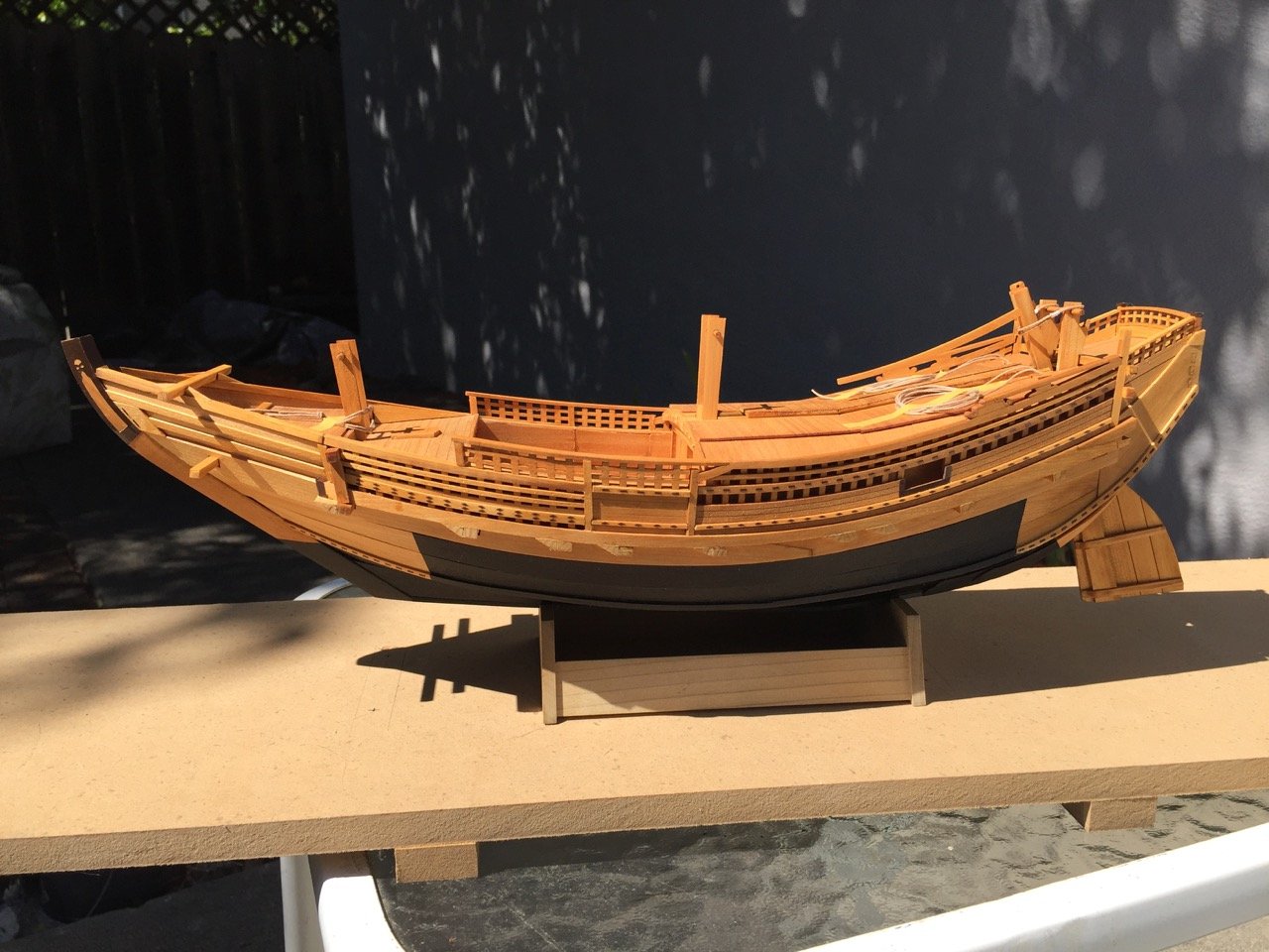
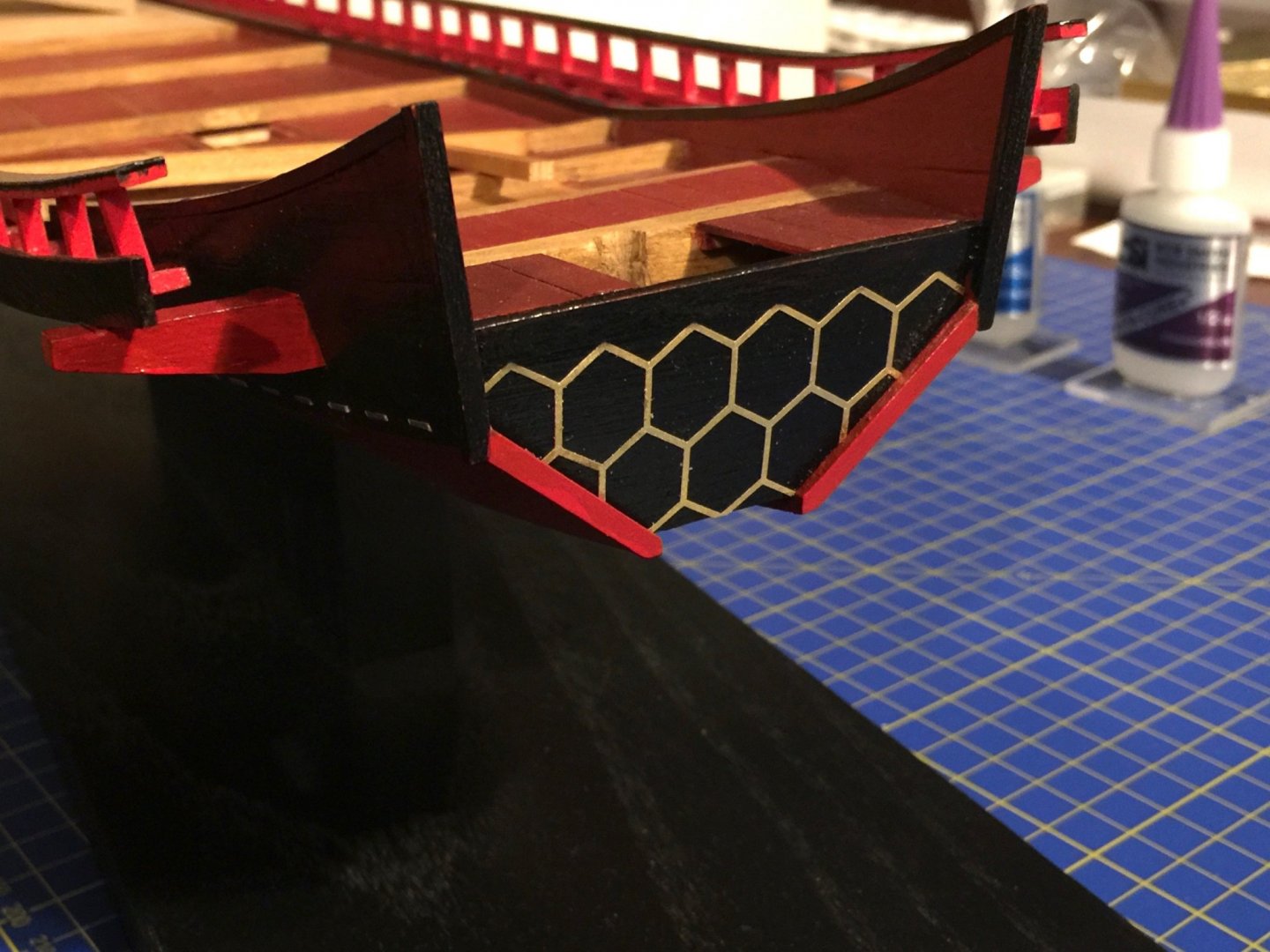
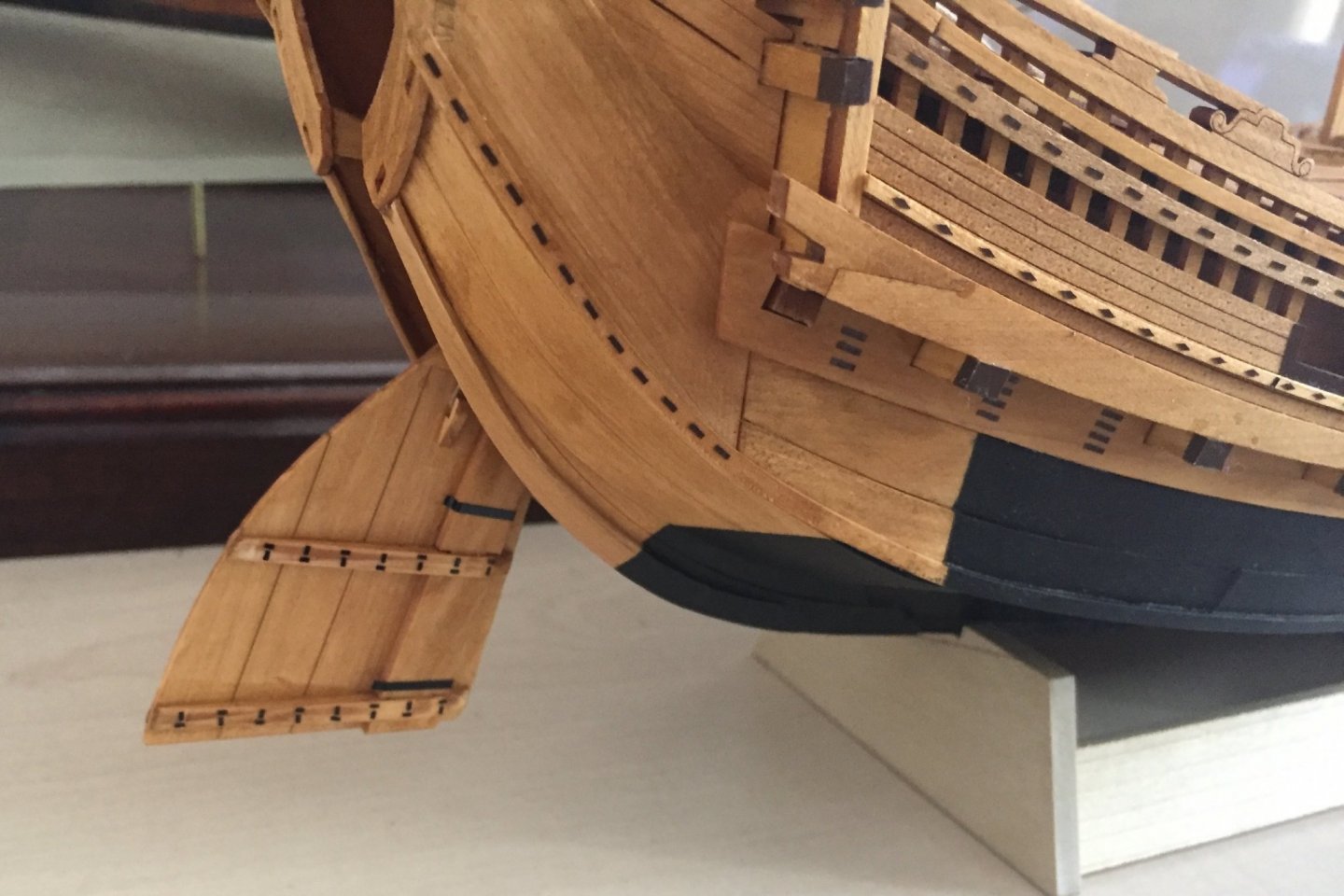
All those brown colored rectangles and diamonds were cut using the machine. The tip of the stem is also covered in this material and was creating using the PixScan mat and photographing the existing parts. The rectangular and diamond shaped mortise covers, however, were designed by myself. They weren't copies from existing copper.
In the below photo, you can see that I've covered the beam ends and added many more detail pieces in vinyl. This includes the black iron parts on the rudder. Like all the rectangular mortise covers, these weren't part of the kit, so I had to draw them up myself.
More of this detail yet to come!
Clare
- FriedClams, bruce d, JpR62 and 11 others
-
 14
14
-
-
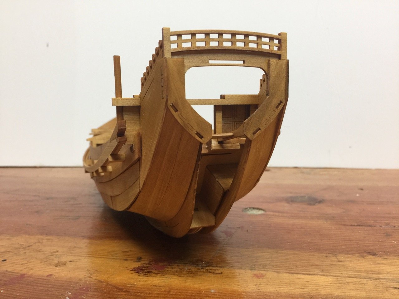
Thank you for the supportive comments, Druxey. The shape of the upward sweeping stern always reminds me of a duck's tail. 🦆
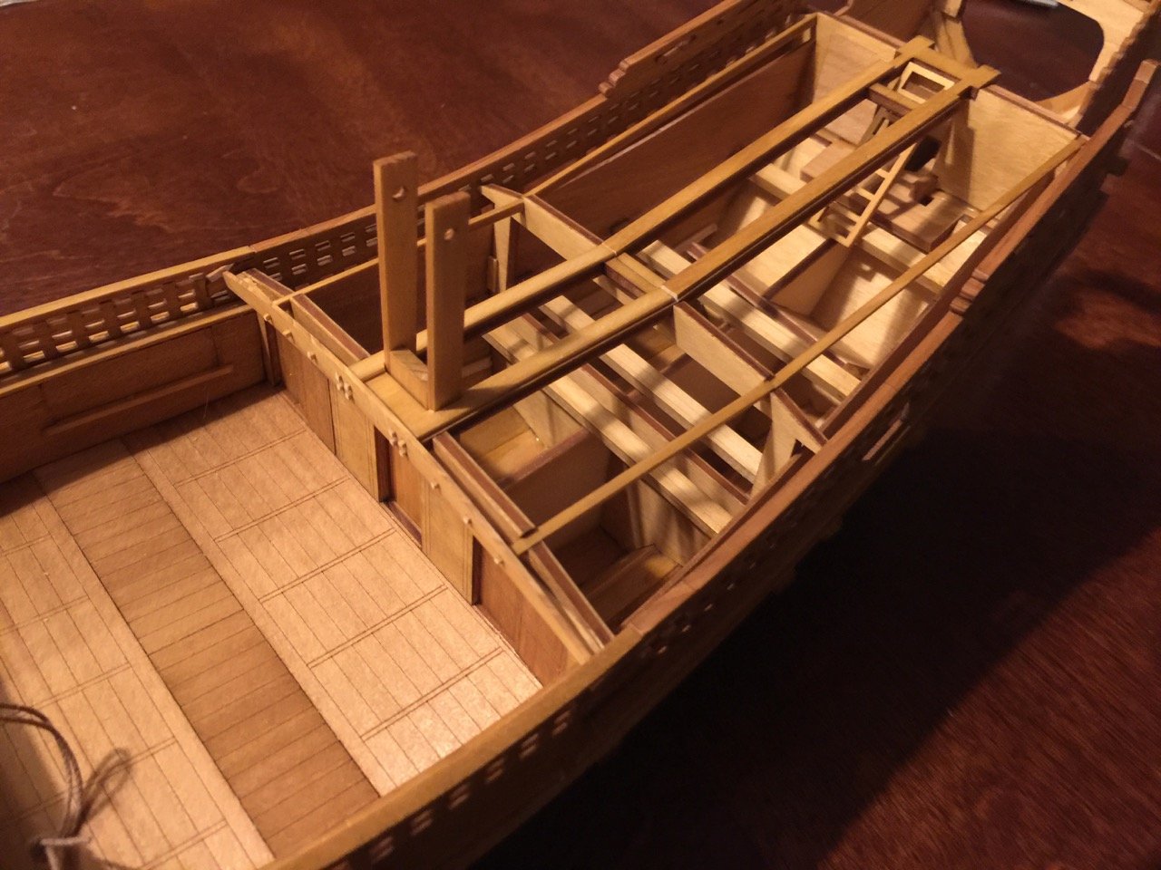
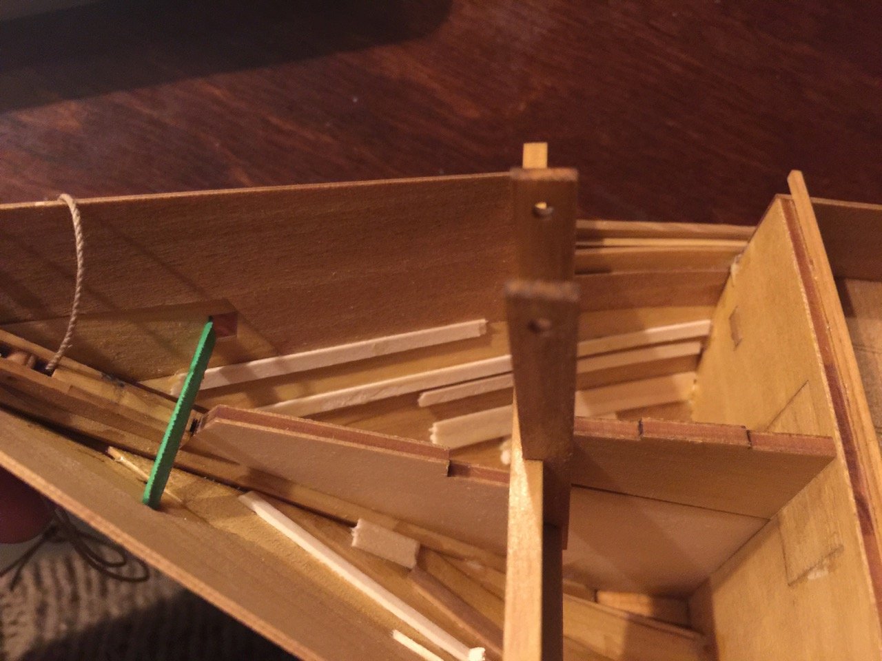
Well, the main cabin gets covered over by deck planking, but not before I get the rudder installed. On this model, the rigging of the rudder is much simplified (like much of the kit). I want the model to stand up to a certain amount of scrutiny. On the Higaki Kaisen model, there is a rope that wraps around the back of the tiller, helping to hold it in the notch in the "great beam" or ōtoko. The rope is doubled and I simply tied it around one of the beams inside the cabin.
The rudder's weight is supported by ropes that thread through wooden sheaves on either side of the rudder. The instructions have you hang the ropes from eyelets installed in a beam over the rudder, to be threaded through each side of the sheave, glued, and trimmed off close to the sheave. So, you basically have two rope ends terminating inside the sheave hole. This is expedient, but not a very satisfying rig for a ship modeler.
I chose to use the eyelets to tie one end of a length of thread through, run it down through the sheave, back up through the eyelet, back down inside the cabin, and to tie it off to a beam inside the cabin. This much more closely resembles the actual rig. I considered hanging a block in place of the eyelet, but I would have had a hard time fitting the block inside the rudder well at this stage. In any case, the rigging is there and I'm satisfied.
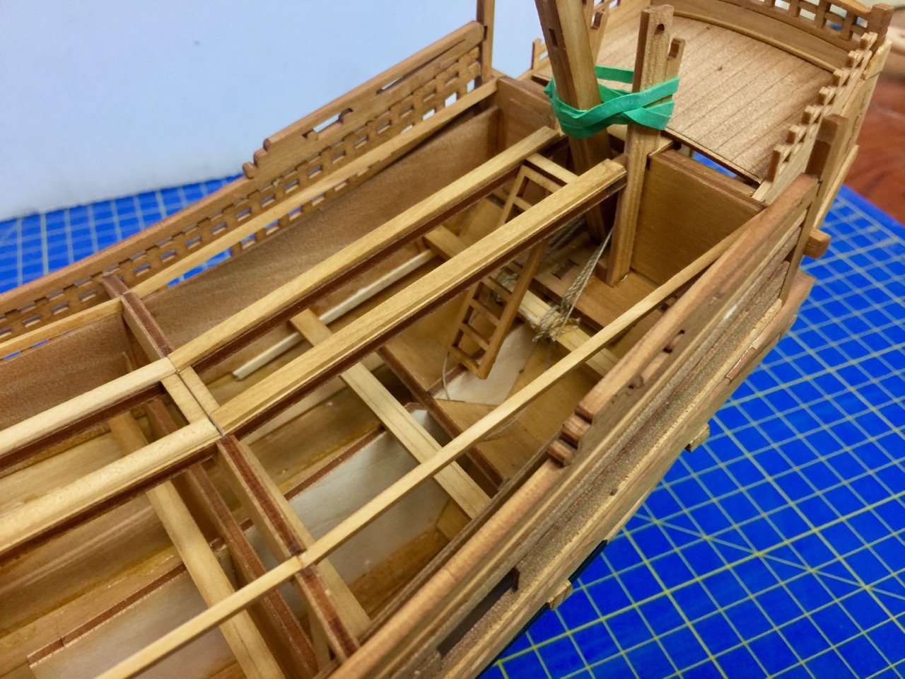
In all honesty, it probably doesn't look any better than what the instructions said to do. But, it's more satisfying for this ship modeler.
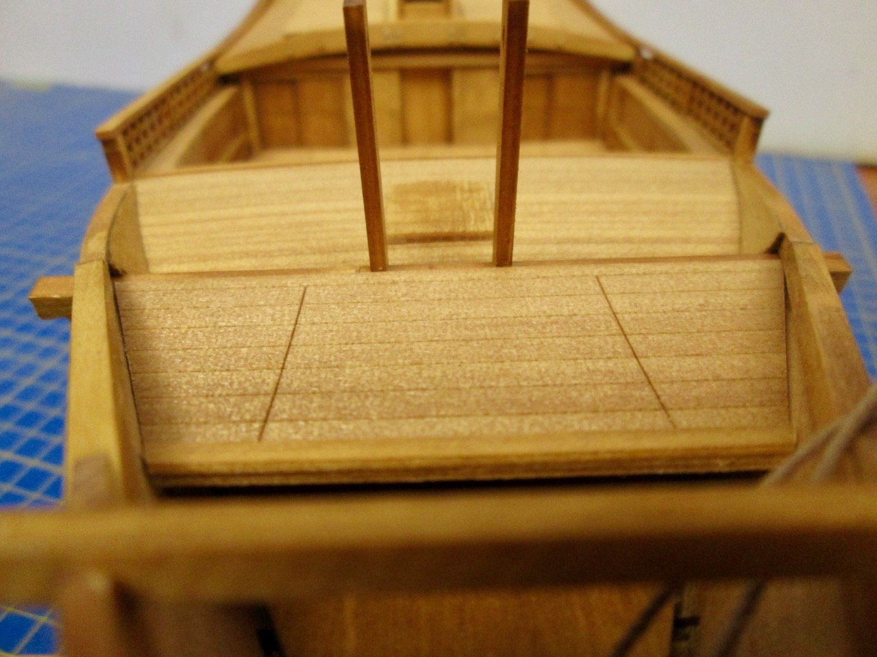
With the rudder in place, I could cover the cabin with the provided pieces of pre-scored planking. I again find the pre-scoring of the planks a bit unsatisfying. But, it does make for a perfect appearance of planks.
The biggest downside is that if anything is off in the area of the planking, there's no way to extend the planks to cover a gap. Or, if there is an error in construction and you have to re-make a piece, it may be next to impossible to make a piece that will blend in with the others. So, it's important to check and re-check all assemblies before gluing a piece into place or cutting something. You HAVE to follow directions, or you run the risk of screwing up the build.
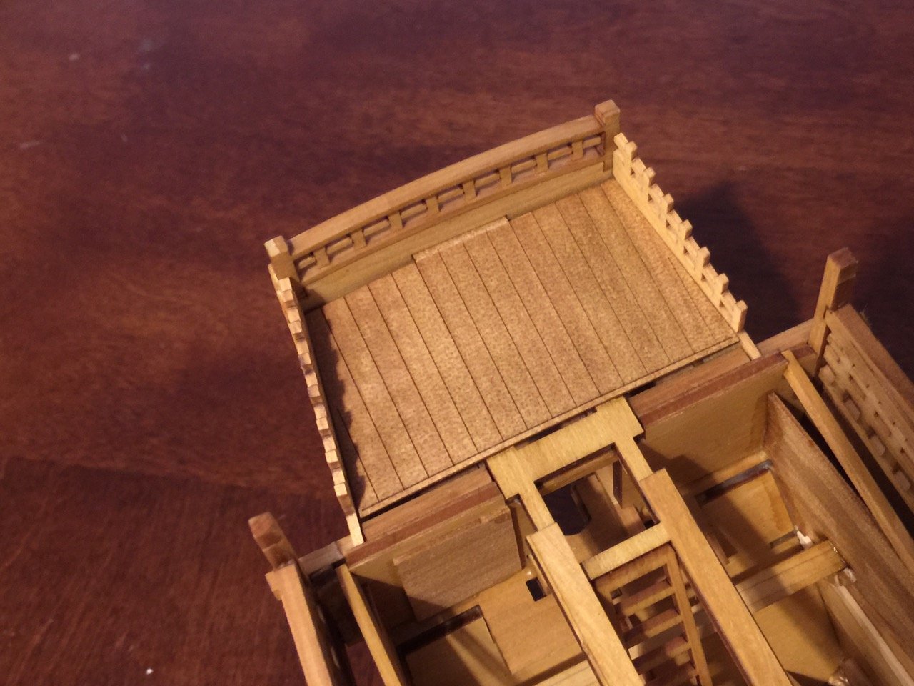
In the above photo, which I actually took during a test fitting of parts, I noted that the tab at the end of the deck piece is totally visible. That won't do. While it's not very authentic as far as I know, I'll probably just cover that edge with a thin strip of wood, like a covering board. It'll look better than that eyesore tab.
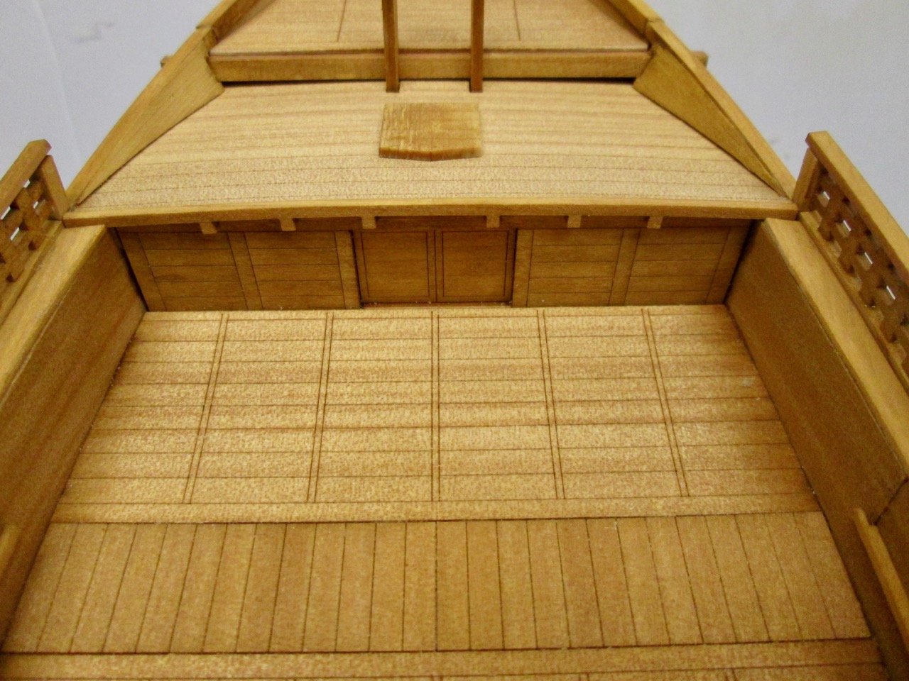
The remainder of the planking went fine, though there is a slight gap at the back end of the cabin, next to beam. It's not all that noticeable except, of course, that my eye goes right to it. I will cut a thin strip to drop in there, which will help.
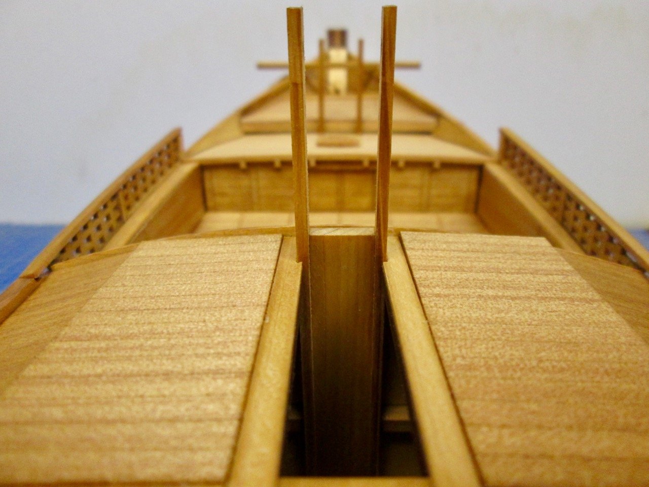
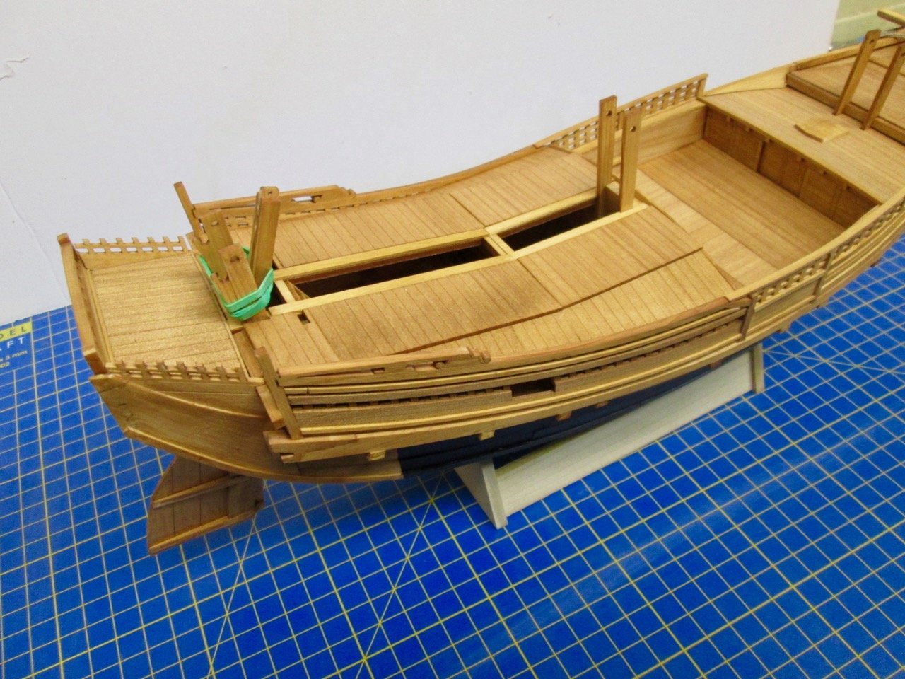
The green rubber band you see in the first and last photos helps keep the rudder from lifting up. Later, a rope will fit in its place, as per the kit's instructions. Also, that long slot down the center of the cabin will be covered. This slot is a real part of these ships, though I believe it's continuous and not blocked by that bulkhead piece. This slot allows the mast to be stepped and un-stepped by the crew. The mast was lowered and removed when at anchor, to stabilize the ship. It was then laid across the tops of those three supports.
-
-
Wonderful collection of photos from the conference!
Sorry I wasn't able to join you, but I tried to be there in spirit.
Thank you Tom for posting these.
- hollowneck, druxey, Ryland Craze and 1 other
-
4
-
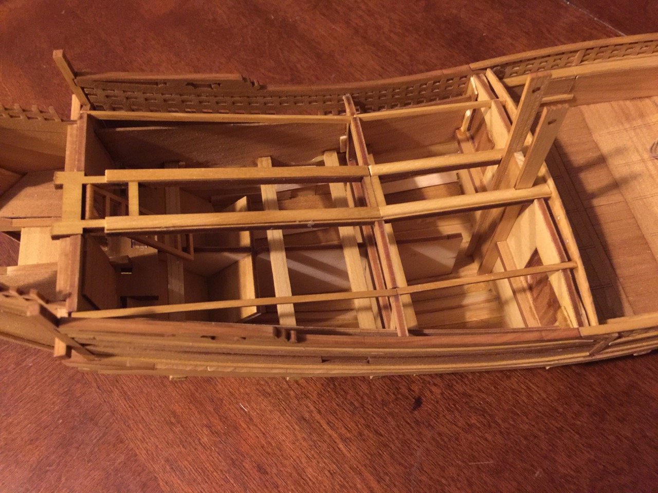
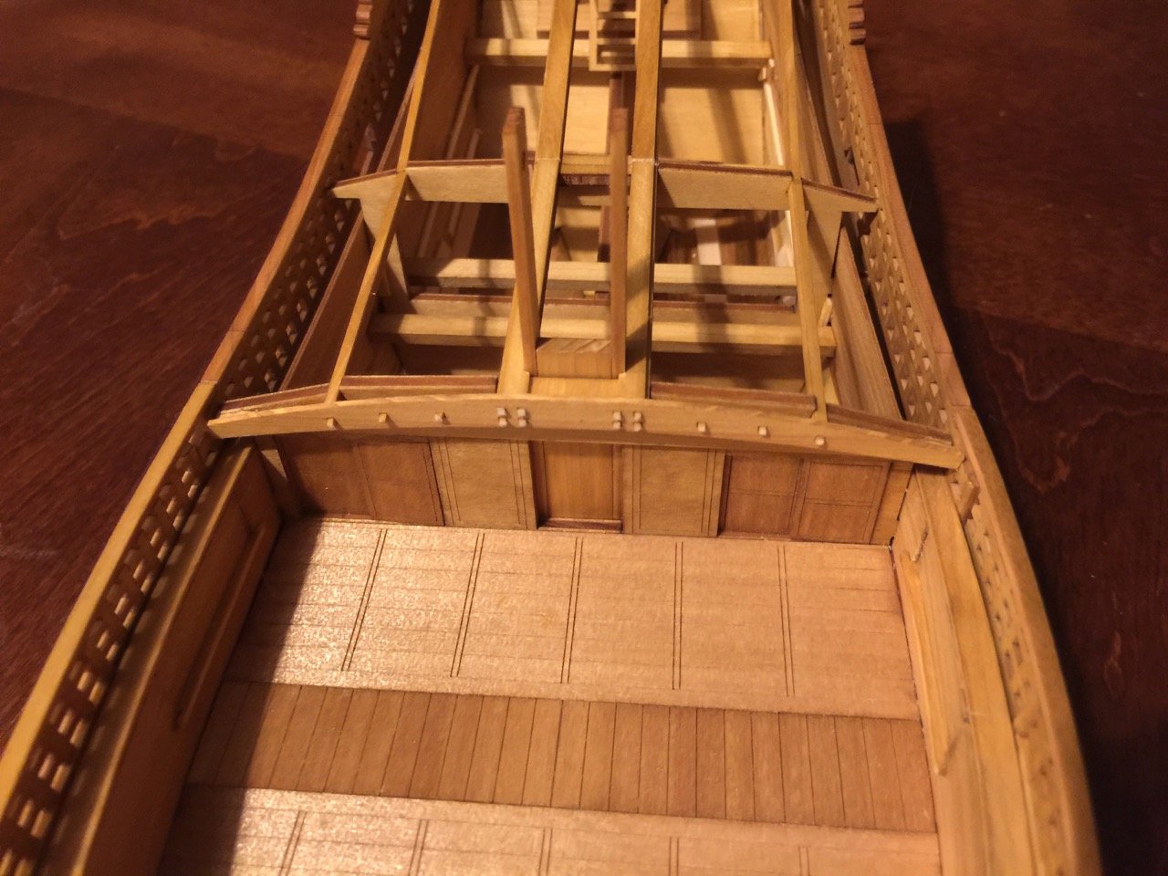
The next phase of construction involves mostly the framework of the main cabin area.
This is very familiar, having built Woody Joe's Higaki Kaisen kit, but I do miss the interior details of that kit. You could probably make modifications to this Kitamaebune kit, to add the same amount of interior detail, but there is no way to see inside, as the doors and the windows are all just solid pieces. It would take some planning to do it, but I think it would be possible.
However, there are other ways to modify the kit to consider. I think I mentioned these earlier, but these ships carried a small boat for loading and unloading cargo, which is a feature not included in either of the Woody Joe bezaisen kits (the sailor's term for Japanese coastal transports). The Kitamaebune also often had cargo piled up high on deck, covered with a heavy straw mat, or they had a peaked roof structure erected over the open deck area to shelter cargo. The boat and the deck structure are still items to consider.
For now, I've added a sill to the base of each loading gate and then added the cutout portions of the bulwarks back in to better simulate the gates. You can see the starboard side gate in the next photo. If I didn't add the details, you'd only see a solid wall.
One of my favorite parts of the model is the arch across the front of the main cabin. Those little square pieces are tennons on the real ship. On the model, these are little 1mm x 1mm pieces you have to cut and glue into place. This is actually a bit tricky to do unless you have a very sharp, thin blade, as hinoki wood this fine is easy to crush when you cut it. I used a scalpel blade, but a very thin razor blade would probably work best – not the hardware store kind, but the kind you can shave with.
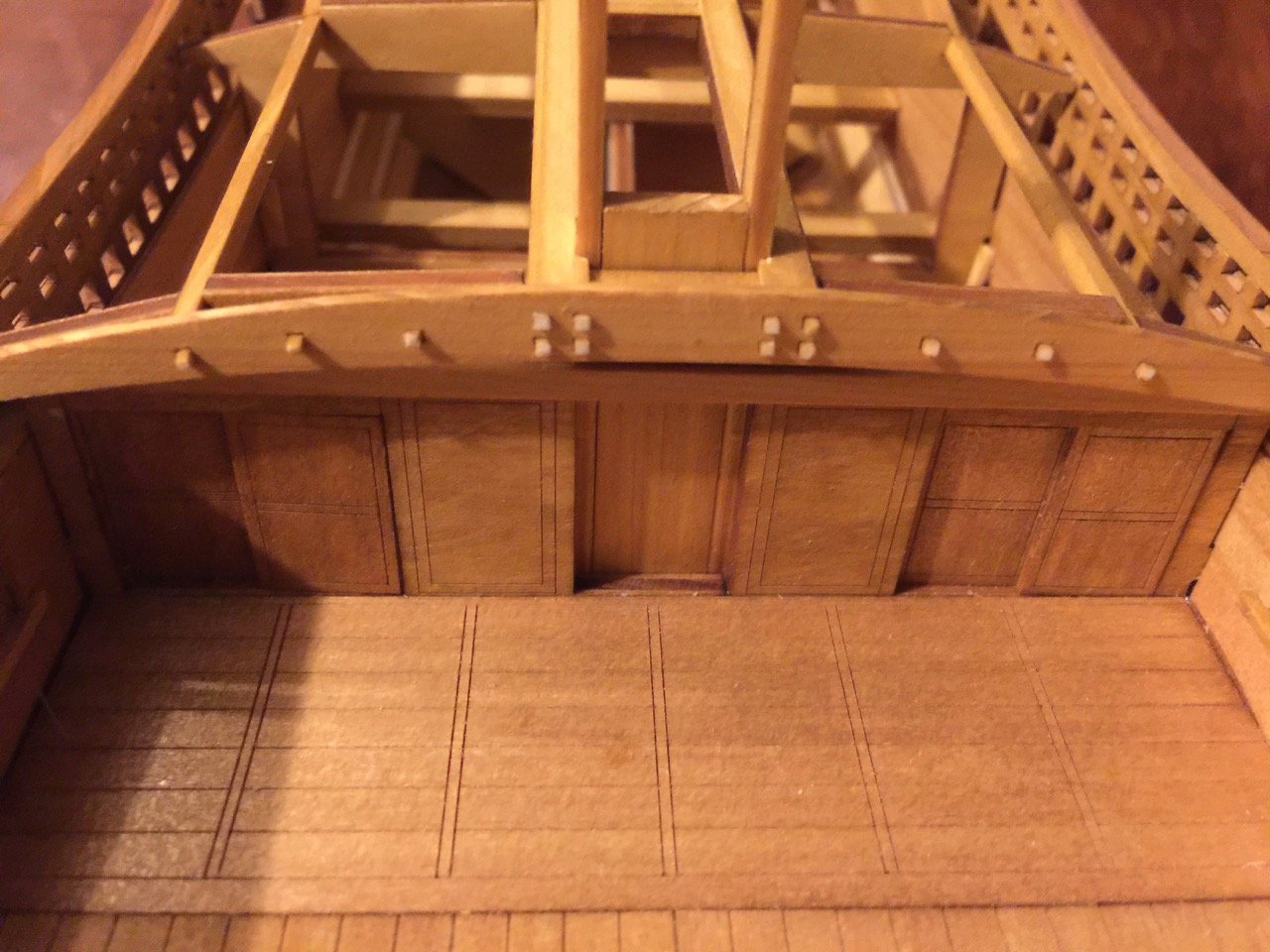
In these close-up photos, you can see that many of these are slightly malformed as the edges crushed slightly when I cut them.
Finally, I started the rudder assembly, as I will be needing it soon. This is another neat piece of hardware on these ships.
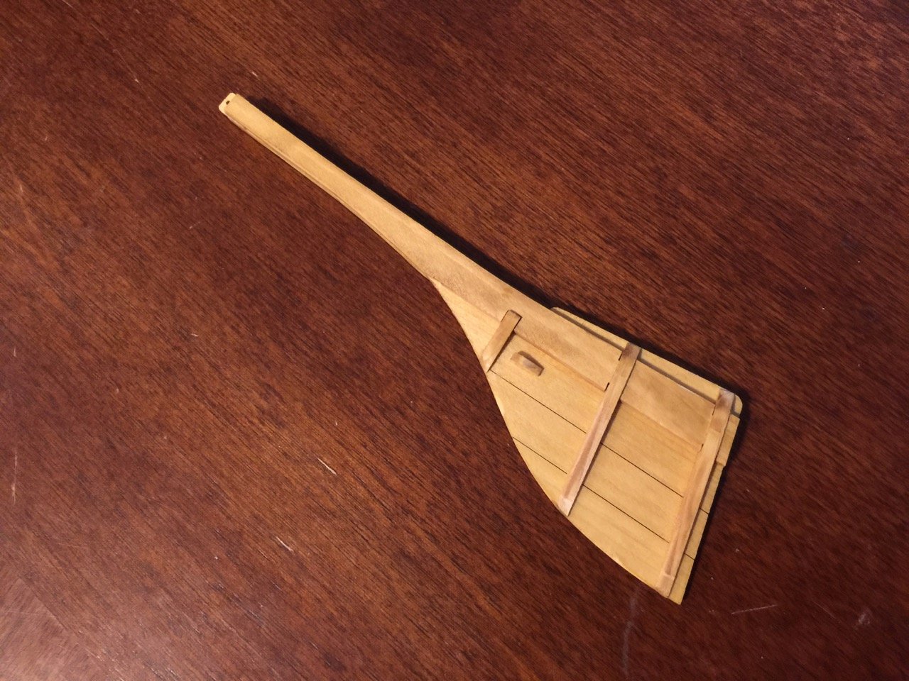
Through the "magic" of laser cutting, the main part of the rudder already has he individual plank pieces cut into it. This whole assembly is made up of 11 pieces.
Below is a better view of the inboard part of the loading gate.
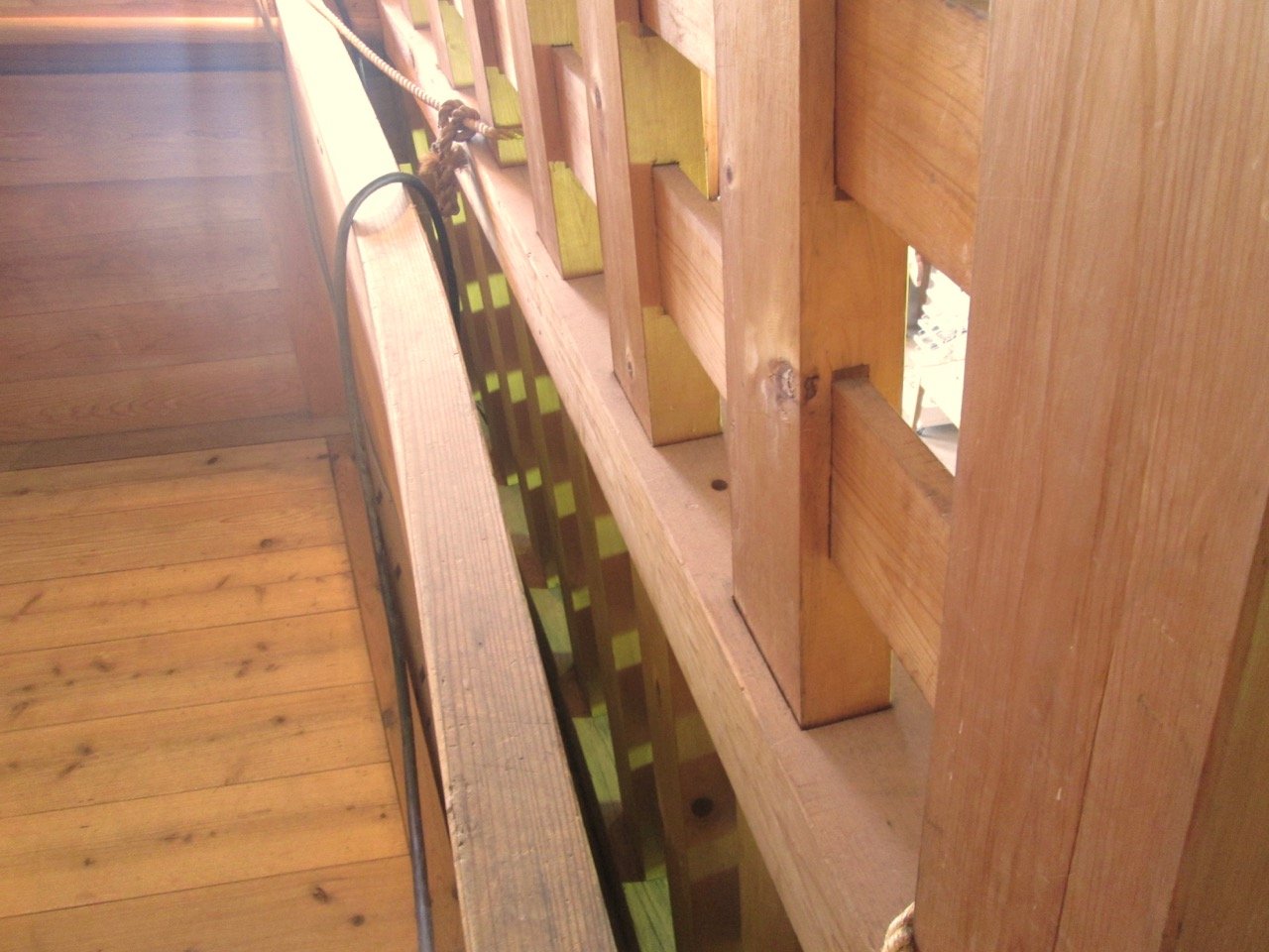
I'll be scoring the piece across the top. On the replica ship I visited, and also on the Higaki Kaisen kit, this piece did not exist. There is a gap between the bulwarks you see here and the external fence you see from the outside of the hull. You can actually look down at the space between the two. I expect that the outer fence flexes somewhat and absorbs the impact of large waves that may strike the side of the ship.
Below, you can clearly see this gap on the Hakusan Maru replica ship on Sado Island.
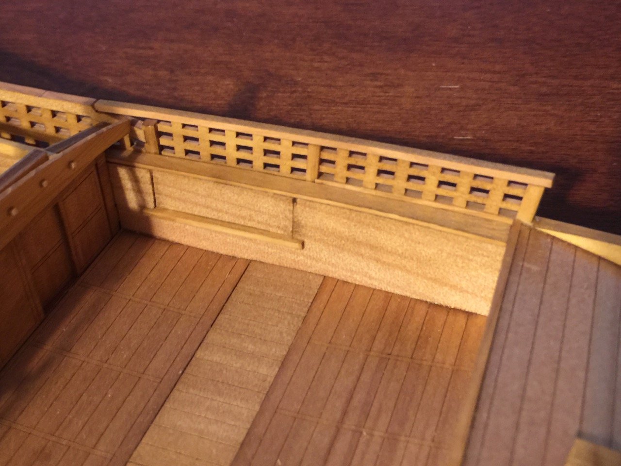
A bit of a blurry photo here, but this is a view from the staircase up into the ship, passing through the starboard side loading gate.
You can see the gate on the opposite side, still in place. Also, that bit of lattice work leaning against the far side is the removable section of the loading gate we're coming through here. All the wooden railing here is just for public safety. Note the slots in the bottom of the photo where that lattice work fence fits into.
-
I'm guessing you got in touch with Billing Boats, not BBUSA. So, what is "the impossible" that Billing Boats wants you to do???
On the BBUSA email, I just checked and they are apparently having problems with spam attacks on their customer registration system. This seems to be happening to a lot of ecommerce sites and somehow affecting the email address.
Someone is looking into it now.
-
And the gate added...
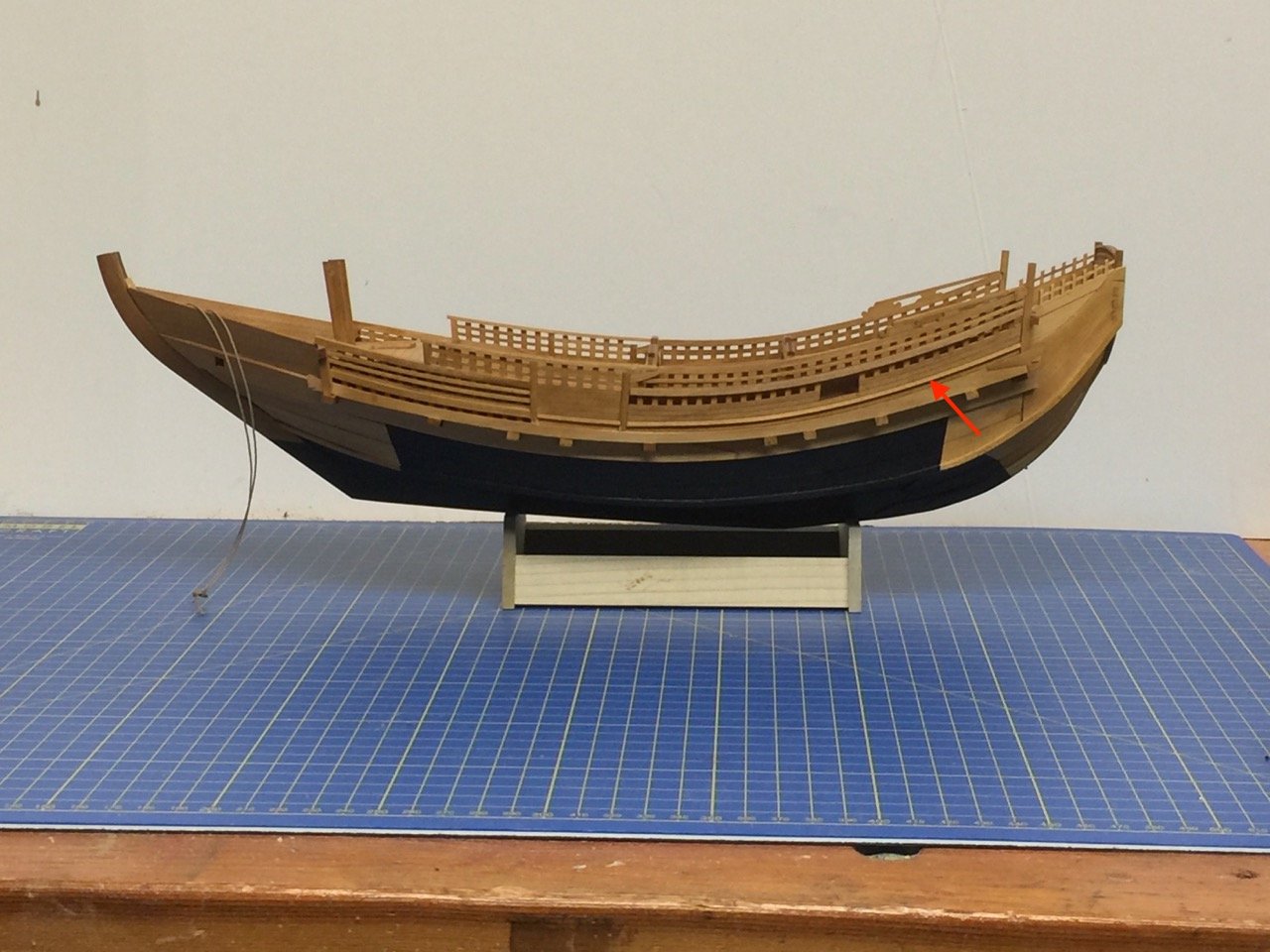
I felt that the bulwarks fence lacked depth, so I added a strip along the larger section under the window opening (marked with the red arrow). This then is a continuation of a similar looking part on the gate.
As I mentioned last time, the forward part of this fence, in particular, is fairly fragile at the glue joints, so I've popped a piece off a couple times already.
-
Hi Rick,
Billing Boats is a kit manufacturer, while Billing Boats USA is a distributor and never made kits. Billing Boats USA went through some changes a few years back – they are still in business, but owned by Ages of Sail.
Email address is customer.service@billingboatsusa.com
Hope that helps!
Clare
-
With the hull painted, the next task was to add the bulwarks fences, again for lack of a better term. This looks pretty elaborate, but there are several laser-cut pieces that make short work of it.
Here's an excerpt of the instructions, showing the placement of the pieces. I didn't take any photos of the assembly process, as it was pretty simple and quick. One thing to note is that there is no structural strength to the assembly, except for simple glue joints. So, at this point, the model becomes a bit more delicate to work with.
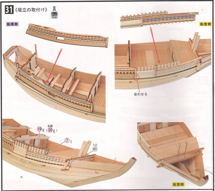
One thing I didn't like is the simplification in the kit, where the actual gate has no detail on the inner bulwarks. This gate allows loading and unloading without having to haul things over the top of the bulwarks fence. In the kit, the outside is fine, as you can see the outlines of the gate. However, on the inner side there's no sign of it. To me, it looks very strange, and is easily remedied.
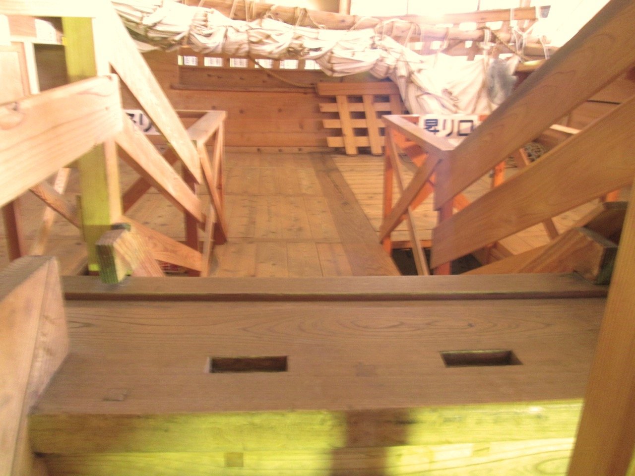
It was helpful to see what this looked like on the Hakusan Maru replica ship. In the photos below, you can see where the gate has been removed to allow visitors to access the ship via the wooden stairway. In the other photos, you can see the grooves cut into the wood into which part of the gate would fit into. There is apparently, a short, solid wooden fence (not all lattice work), that is more water tight, that fits into slots toward the inner side of the bulwarks.
On my model, I cut away the area of the inner bulwarks to allow for the placement of a sill and inner loading gate.

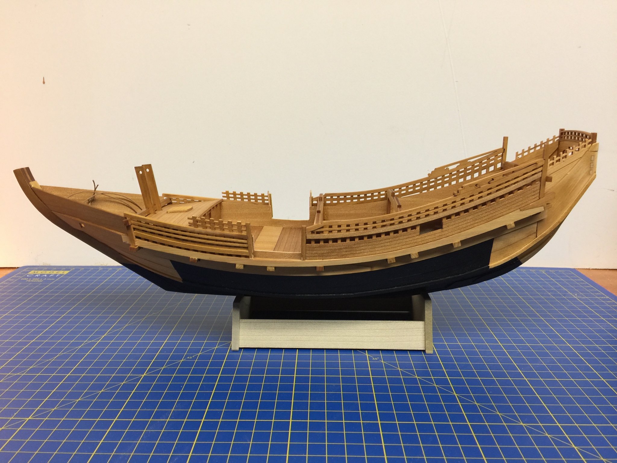
Note that I also completed the stand, which is a standard Woody Joe ship model stand. I also drilled a couple holes in the hull bottom and mounted a pair of brass pins (3/32" rod) into the base, so the model won't slide around on it.
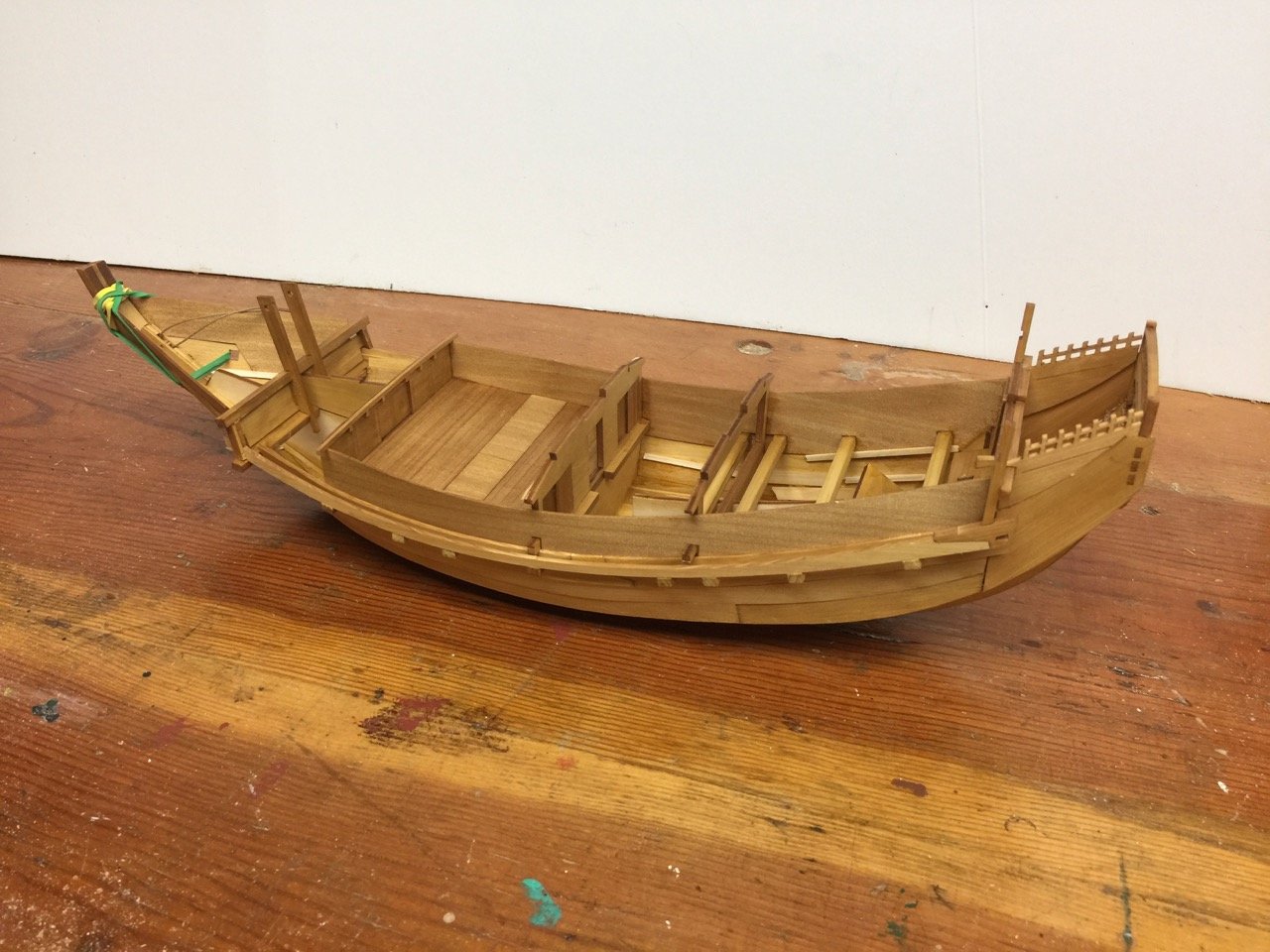
With the bulwarks fences in place, the model is definitely starting to look like a Kitamaebune.
-
-
-
Actually, all the Victory Models line of kits starts with a 1300. The 04 indicates specifically HMS Vanguard. I don't know of a way to identify any revisions of the kit. The only variances that I've been aware of is the current version vs. the old Model Expo version, though I imagine some other things have changed.
I agree that if you purchase from a major supplier, like Ages of Sail or Cornwall, I'm pretty sure they go through enough of these that they will have the "current" version, good or bad.
-
I'm sorry that I don't have any photos of the pieces I cut for the stern trim. I had cut, test fit, trimmed, test fit, and glued them into place, and they seemed to look just fine. So, I started to mask the bottom of the hull for the lower hull's paint job.
I've seen slight variations on the paint scheme, but if you look at paintings, wood block prints, drawings, the replica ships, they're all pretty similar. I don't know why it was done this way.
I masked off using Tamiya yellow masking tape, and the paint is Liquitex, an artist's acrylic.
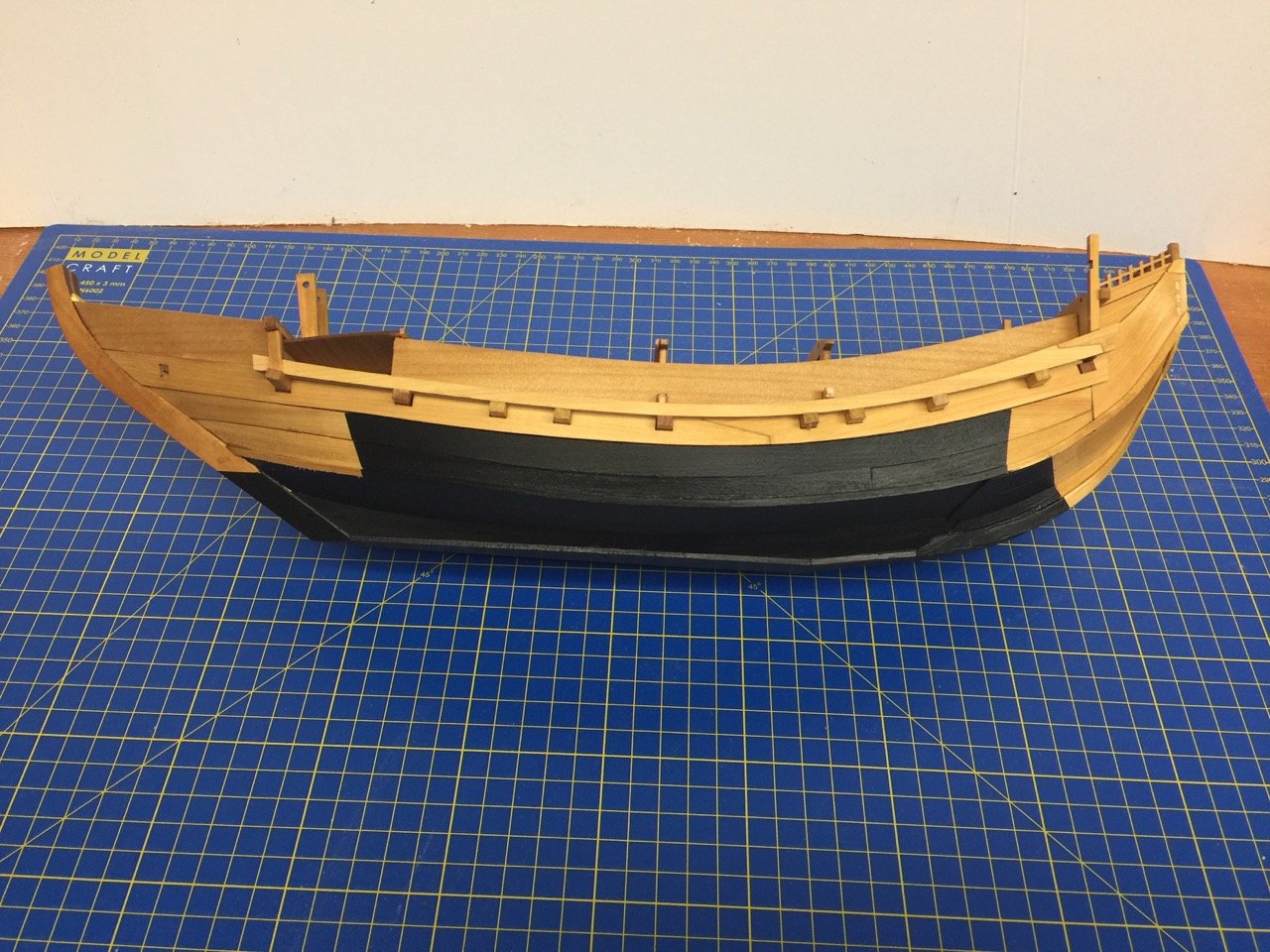
You'll notice in the last two photos an angled deck near the bow. You're looking at its underside, making it look dark. This, and the vertical supports were added, but I didn't post any info about it. This brought me up to Step 28 in the build.
I was very happy to get to this stage in the build. The bottom paint give the model a more interesting, complete, look. Plus, it covers up all those errors in the hull.
-
24 minutes ago, mtaylor said:
I too did the Estes rocket thing back in the day. One was the Mercury but the beast was Saturn V. Lost the Saturn V when one of the motors (it had 5 as I recall) blew up on launch. Irritated me but it wasn't uncommon as some their motors did blow like a fire cracker.
I tried to build the Estes Saturn V kit, but it was too much for me. The best I did was the Orbital Transport. First launch went amazingly well. Booster came back down by parachute and the orbiter flew circles around it on the way down.
Worst was a windy day and the launch of the "Interceptor" fictional Air Force craft with wingtip rocket pods. Flew straight up and a gust caught it about 1/3 way up and it made a right-angle turn. Had to go chase it down, but it was a fun flight.
- Old Collingwood, CDW, mtaylor and 2 others
-
5
-
Growing up next to Vandenberg AFB in the 60s, I remember weekly missile launches. It was the norm in the town of Lompoc, where you'd be inside, hear a rumble, the windows would start to rattle, you rush outside along with every family in the neighborhood standing out on their lawns, and watch the rising streak of smoke.
You'd watch and look closely so you could see the puff of smoke from the staging. After a while, all you could see was the speck of light from the upper stage engine fading into the distance, and people all wandered back into their homes.
They were all unmanned flights – a lot of them, test flights.
They were very inspiring to a kid at a time when the space program was in full swing!
- lmagna, Old Collingwood, Canute and 3 others
-
6
-
Thanks Druxey.
Fortunately, with what you might call a facetted chine hull, one with many flat sides and angles, these gaps aren't as pronounced as they would be on a smooth planked one.
I had a similar problem on the Higaki kaisen model, but only in one place. I mentioned the issues I had to Woody Joe and that an additional bulkhead at the bow might have helped.
Initially, I though the Higaki kaisen had a better designed internal frame that make for better fitting plank pieces. But, I looked back at my old photos and see that it was about the same. I don't know why I had more trouble this time.
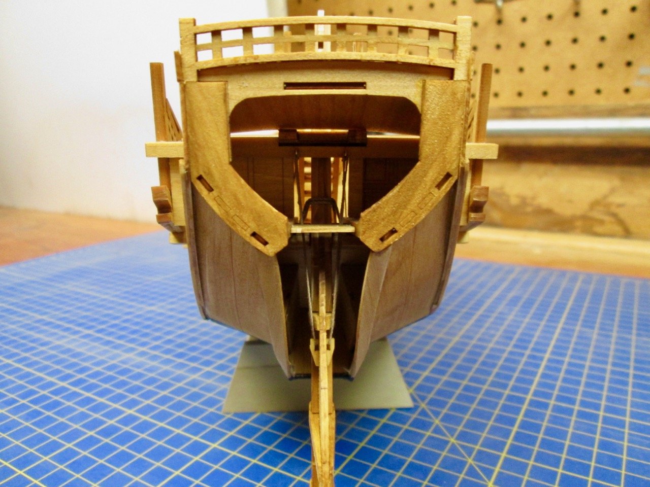
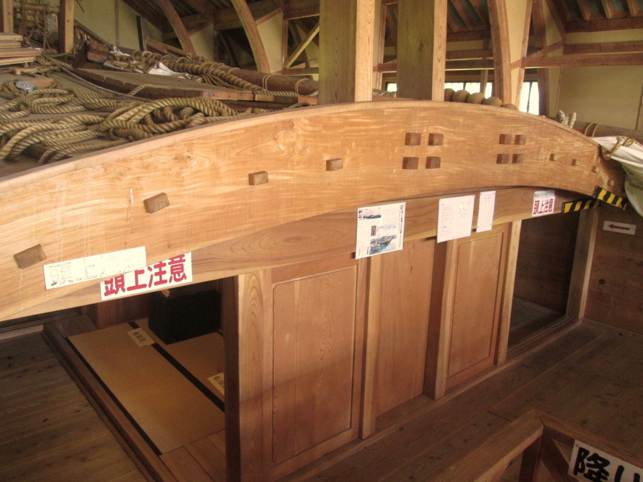
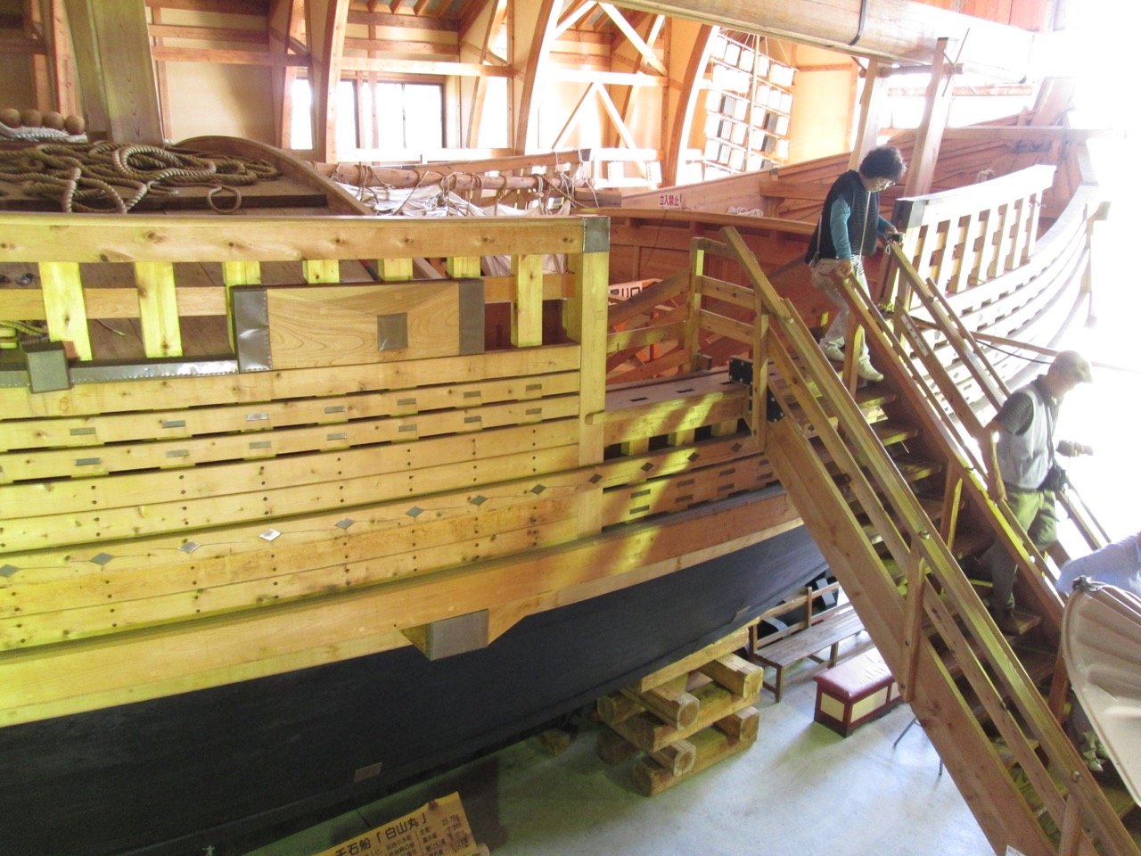
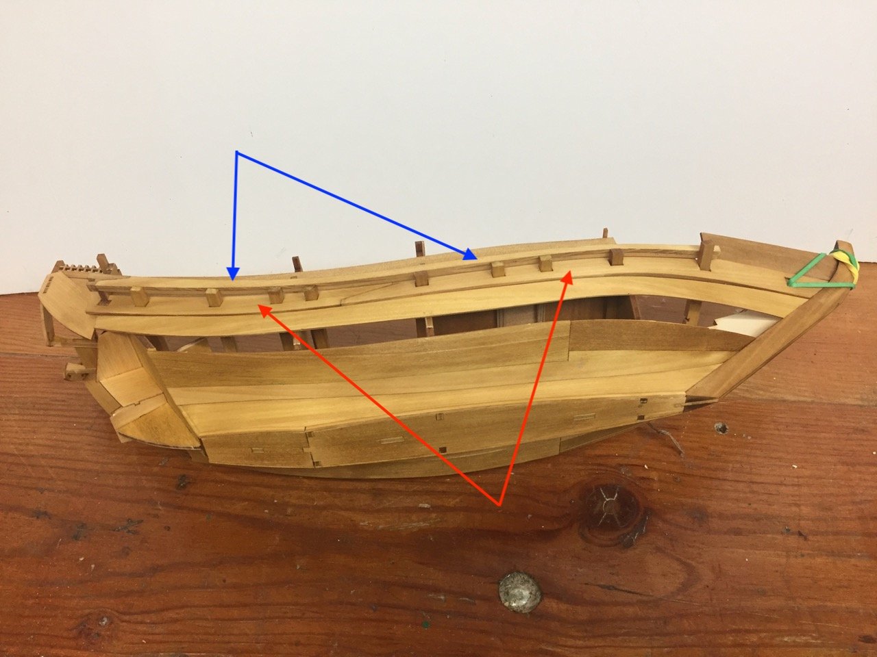
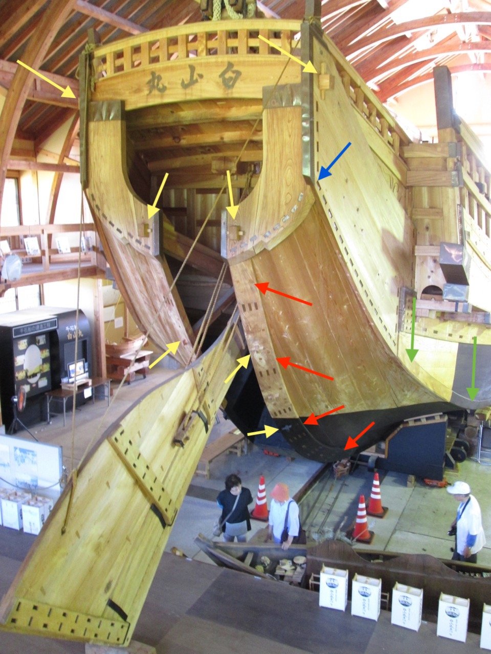
In any case, I looked at my photos of the Hakusan Maru again, the ship I took photos of on Sado island, and noted some of the details that appear on that ship that don't appear on this model. Now, these ships had some variations to them, so certain modifications are just another option. But one seems to be certain on just about every replica and model I could find. That is the heavy plank at the edge of the rudder well opening.
I marked up a photo to show this plank and other features. This photo also gives you a better sense of scale as it has some people walking around.

The red arrows point out this heavy plank. If you look at the last photo of my model, the end you're looking at is the edge of the hull pieces. So, I'm going to see if I can add these pieces, though it might require a little trimming of the rudder well opening in order for the pieces to fit correctly.
In any case, I also labeled in green a strip along the chine of the hull. This strip runs all the way to the bow. On some ships, it appears to run all the way back to the stern where the blue arrow is shown. On this ship, it actually stops at that last green arrow and there is a kind of fashion piece there. I'm going to take the simple route and run the strip all the way back.
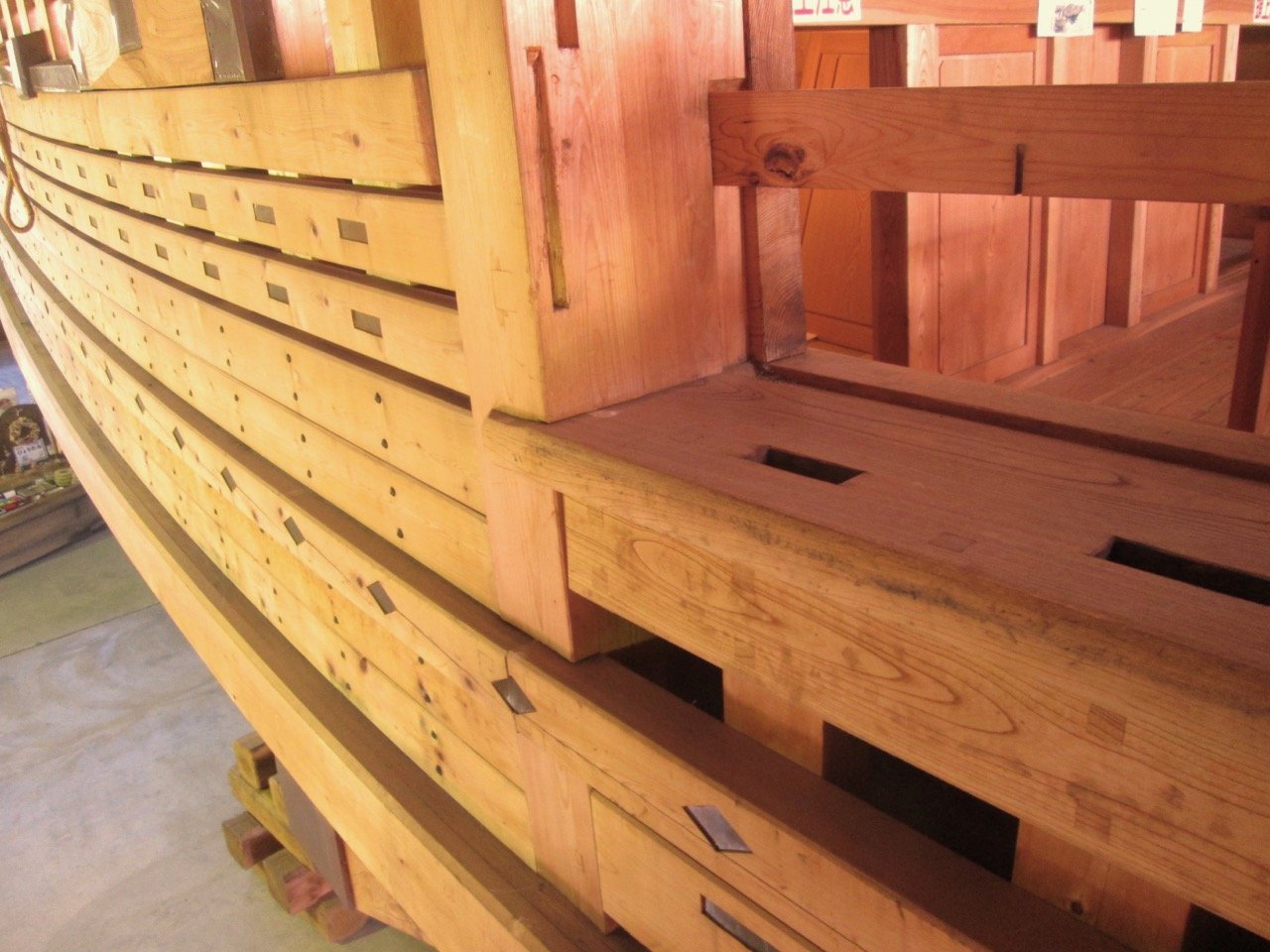
Finally, I thought I'd point out another feature that doesn't show up in these kits: There are tenons sticking through the planks where I've marked with yellow arrows. These have wooden keys that lock them into place, which you can see in the photos. I'm going to try to simulate the tenons – easy enough since I just have to glue wooden squares into place. I don't know that I'll be able to simulate the keys due to the small size.
First Modifications
Okay, I already did the easiest modification, and that was to add that strip along the edge of the chine of the hull. A very simple process of measure, cut, bend, trim, and glue.
The application of the strip wasn't perfect, particularly on the port side. Also lining up right on the edge means that I need to file the edge in a couple spots where I didn't get it quite exact. Minor issues.
Note the pencil marks along the edge of that bottom piece, aft. I've been testing out shapes for that edge plank and found that to get them to fit properly, I'd have to trim away that area.
Next step is to make the pieces, trim away that section of the hull and glue them into place.
-
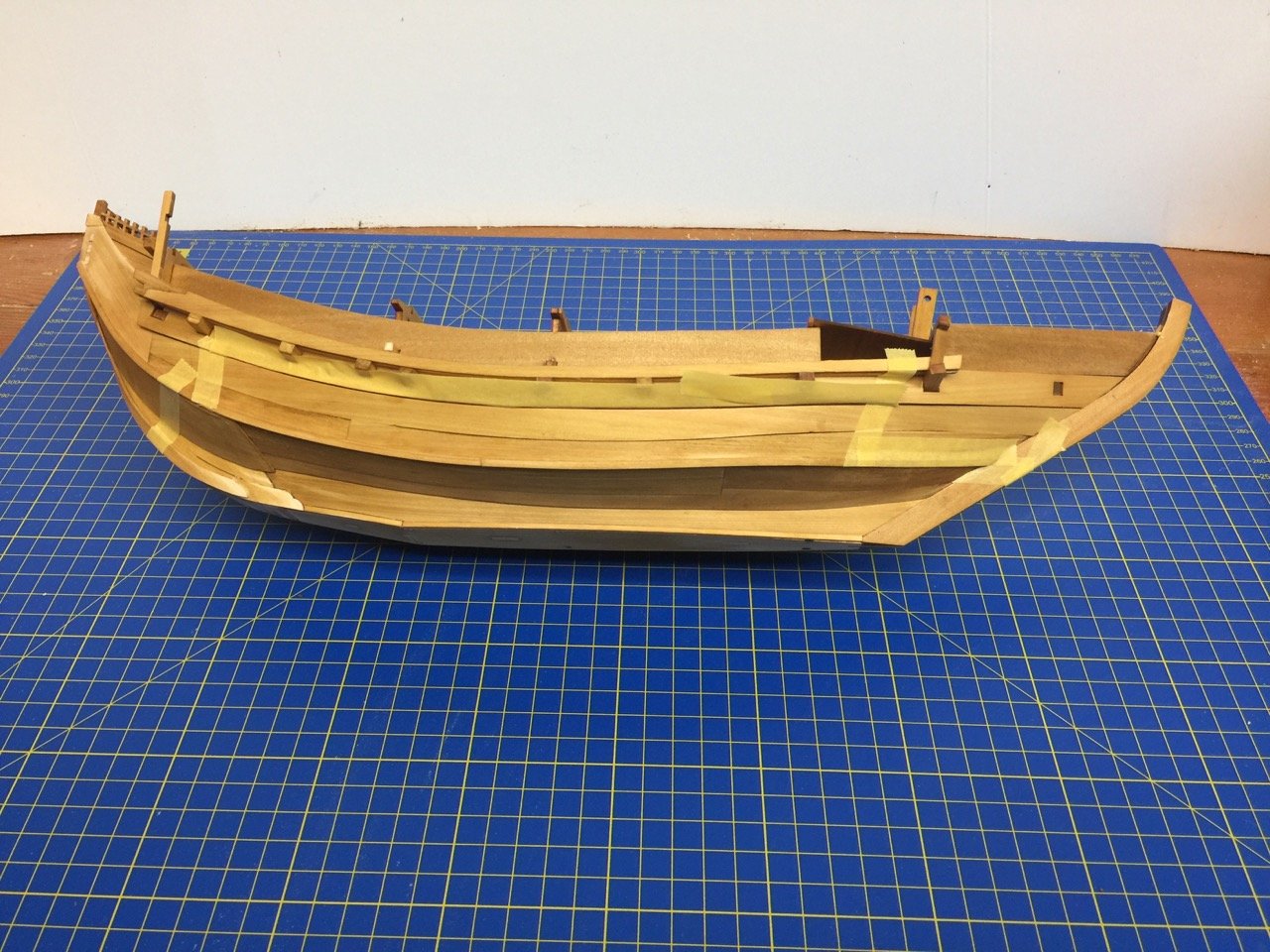
Finishing the hull planking
As you saw from earlier pics, I had already started adding the last of the hull pieces, a.k.a. "planking". I finished up everything through Step 26 in the instructions.
Construction was certainly not "trouble-free". The main issue I had was that I ended up with small gaps between many of the hull pieces. My biggest concern was that light might show through these gaps. Otherwise, most of these were not very noticeable.
The biggest exception was the interface between the main hull pieces and the stern assembly. As you can see in the photo below, there was quite a considerable gap (inside the red circle). I don't know why the gap, but it must be that I left the hull somewhat wide close to the stem. I believe this comes from there not being a bulkhead close to the bow to set the proper curvature to the hull there.
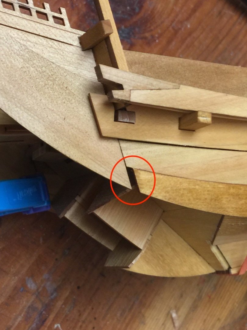
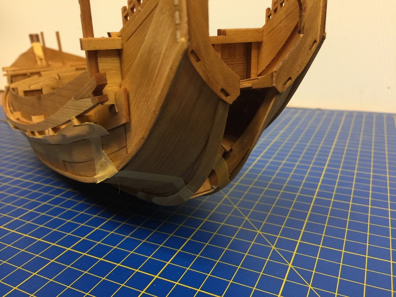
The piece is a simple one and I was able to find sufficient scrap wood among the laser-cut wood sheets in the kit to fashion replacement pieces.
As for the other gaps in the hull planks, I ended up using scraps of wood to "light seal" all the small gaps. There were a lot, and you can see all the wood strips I glued into place to hide them.
I felt that, in the end, blocking these gaps with wood would look better than sealing them with wood filler. Some of the gaps will also be hidden when I apply a paint scheme which covers the lower hull.
At this stage, with the hull planks all in place, I'm starting to consider some modifications to the kit to make it look more like a real kitamaebune. I'll point out those as I progress further in the build.
I have to say that I was a bit disappointed and frustrated with some of the problems I had with the fit of the hull parts. Others building this kit may or may not run into similar issues. But, I have to say that after getting it all together and cover the gaps from behind, I'm pretty happy with the project over all.
The Kitamaebune kit has more frustrations than I remember when building Woody Joe's Higaki kaisen kit, but it really does go together more quickly.
-
Sometimes it seems like the old companies don't really appreciate their own early work. So, maybe it's just as well they are gone and replaced by a company that understands the importance of these old models. At least we're lucky enough to be able see them again and maybe build them.
- Old Collingwood, CDW, mtaylor and 2 others
-
5
-
I've admired this model kit since I was a boy. A friend of mine had built it and I loved that it had the whole launch pad complete with the erector truck. May not live up to modern kits with their photo etched brass, but the kit's still a classic.
Congratulations on your find!
- CDW, mtaylor, popeye the sailor and 2 others
-
5
-
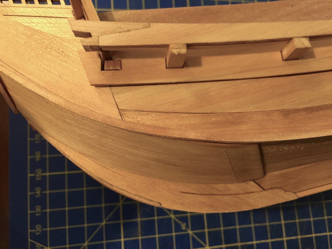
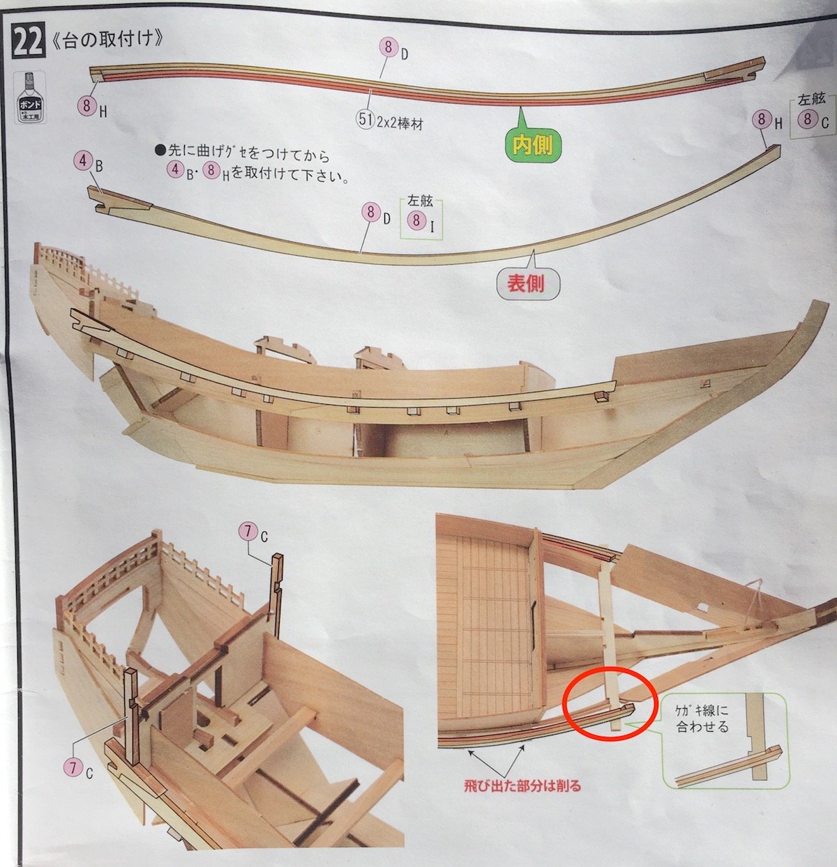
Something I neglected to mention in my last post is that each dai, the railing that runs along the tops of the beam ends, is actually made up of four pieces. So, there are pieces glued to each end, and a 2mm x 2mm strip along the bottom of the back side. That strip glued along the back will make it impossible to bend the assembly to the proper curve, so you really need to pre-bend the wooden pieces first, then glue them together. If the 2mm x 2mm strip is cut to length first, it will have to be shortened slightly to fit.
The dai rests on the forward most beam, on which Woody Joe has scribed an line to help align the dai properly. I've circled the spot in red in the image below. So, it's important to look for that line. It also means that it's important to glue that piece in "right side up" in the earlier step.

Another note about that forward beam. The beam is stepped, or notched, and the step is perfectly vertical and helps give the hull planking the proper curve. Now, the thing is, where the step hits the hull plank, the hull plank, which is angled, doesn’t fit the perfectly vertical notch nicely. The ship modeler in me wants to adjust that step, so that it fits flat against the hull, but this would be wrong.
With these Woody Joe kits, if it needs to be filed or sanded, they’ll let you know, and the fit is as the designers intended. So, some ship modeler tendencies need to be suppressed with laser-cut models. However, there is some filing or sanding that does need to be done, as the ends of the beams need to be flush with the curvature of the dai.
The last part of this construction step is to mount two vertical posts on top of the dai. These support the aft ends of the bulwarks “fences”. Because alignment is particularly important with laser-cut kits, I took the bulwarks fence piece that is installed in some later step and use it as a guide to help me make sure I glued the posts in at the correct angle.
-
Thank you, Druxey. In fact, the painting in the first post shows three ships with the same markings. This painting was, I believe, an ema, or votive painting commissioned by the ships' owner.
By the way, I was wrong about these ownership markings being black. I saw a couple photos recently showing a ship with orange or red markings, and another photo showing a ship with one marking in black and another in orange or red. But, that's the first time I'd seen a color other than black.
I don't know if I'll be adding any marking on mine, as I will likely ruin the pre-printed sail, which looks very good.
- Canute, FriedClams, mtaylor and 1 other
-
4
-
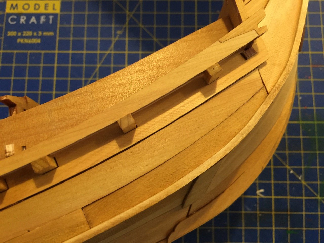
Getting back to the build, steps 19 through 22 involve the addition of some hull planks, a plank called a noke-dana, and a piece referred to in the instructions as a dai, which is the base for the bulwarks “fences” for lack of a better term. In the photos below, the red arrows point to the noke-dana, while the blue arrows point to the dai.
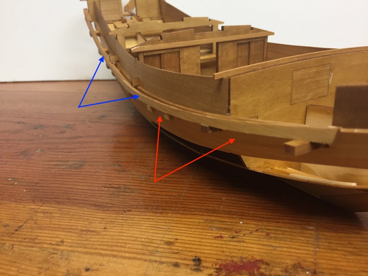
I don’t really understand the meaning of the term noke-dana, except that danaor tanais the term for a plank. This piece is a heavy plank that is pierced for the main beams, locking them into place.
In the kit, this piece is, of course, laser cut, but is actually made in two parts connected with a scarf joint. The tricky part is that it has to be gently bent, so, again with the dampening and bending it over a large round surface. I did this after the two sections were glued together using Titebond II, which is water resistant, making sure to dampen the wooden piece, but not at the joint.
Once this piece is glued into place, the beams are cut and put into place. These are among the few structural pieces that have to be cut to size from provided wood stock. These beams protrude through the holes in the noke-dana – I’m sure that on the real ship they lock into that piece in some very clever Japanese way. The dai is mounted onto ends of these beams.
- Ryland Craze, J11, Canute and 10 others
-
13
-
Imai is Woody Joe's predecessor. They generally made kits in larger scales and sizes than Woody Joe does now (except for the Shin Nippon Maru kit, which is slightly longer than this Susquehanna kit). I wish there were still this and the 1/50-scale Kanrin Maru kits available.
Woody Joe makes great kits, but nothing is more impressive to display than a large scale ship model!
- Canute, RickyGene, Ryland Craze and 2 others
-
5


Kitamaebune by catopower - Woody Joe - 1/72 scale
in - Kit build logs for subjects built from 1751 - 1800
Posted
Hi Gary,
Thanks for the nice comments.
My own cutter is a Cameo Silhouette. The vinyl I use it .003" thick. It can certainly handle thicker, heavier material, but I don't think you could cut styrene with it. A more powerful cutter is the Cricket Maker. It can cut with much more pressure and can cut thin wood. I've seen mention on the Internet of someone using multiple passes using a Cricket Maker to cut 0.040" styrene. So, yes it's definitely be possible with that machine.
I specifically bought the Cameo machine to cut vinyl and paper. Also, I chose it because I much preferred the drawing software that comes with it.
I tried the Cricket software, but it stores drawings on the Internet, and you need an Internet connection to use it. That's certainly not a problem, but I don't like that I can't just use the machine anywhere with drawings I store on my computer.
Clare