


Glenn-UK
-
Posts
3,004 -
Joined
-
Last visited
Content Type
Profiles
Forums
Gallery
Events
Posts posted by Glenn-UK
-
-
Foremast Construction WIP
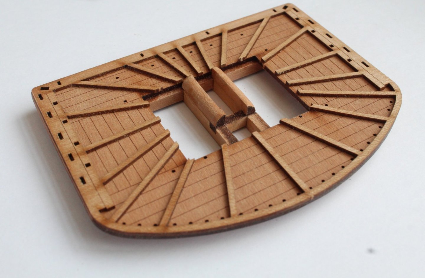
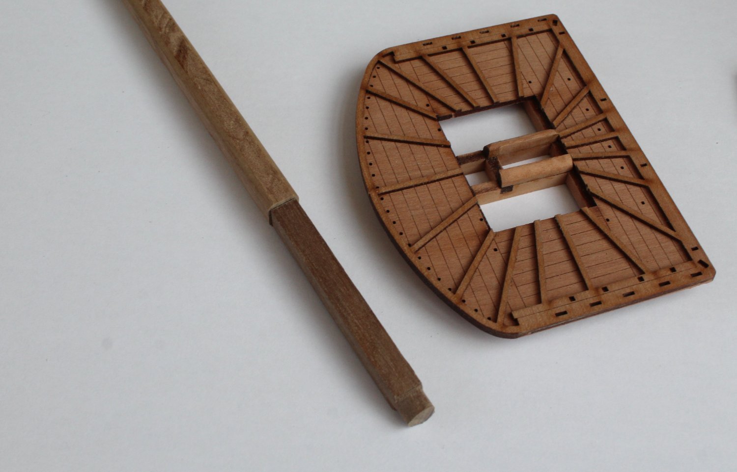
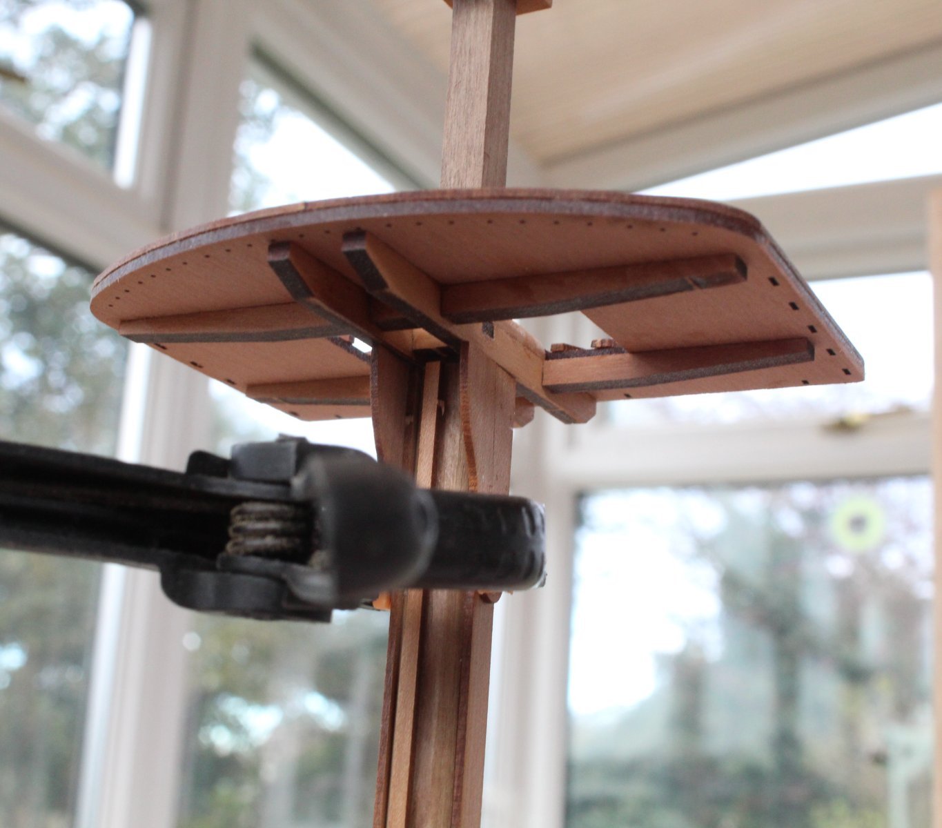
I have started work on the lower foremast. The first task was to construct the platform. It was a simple task to assembly.
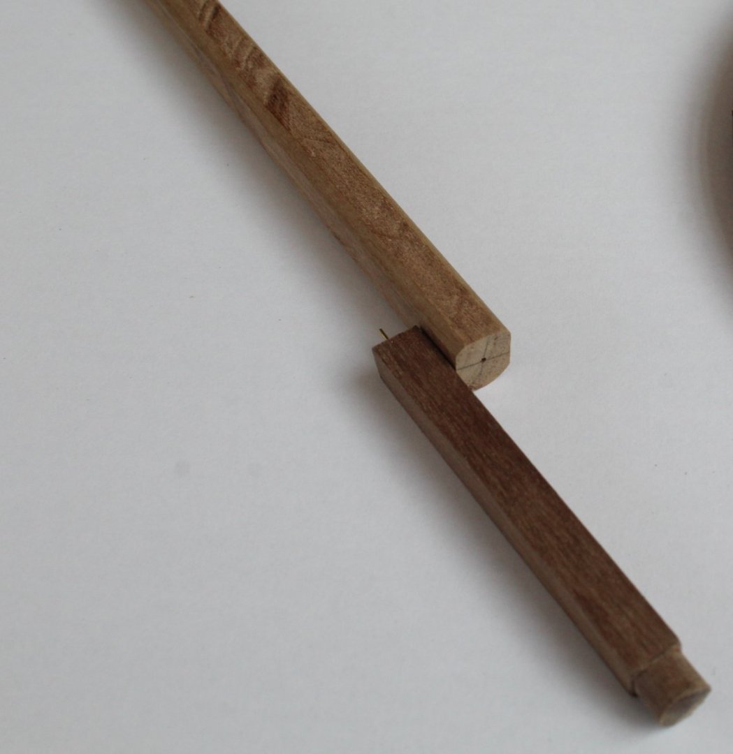
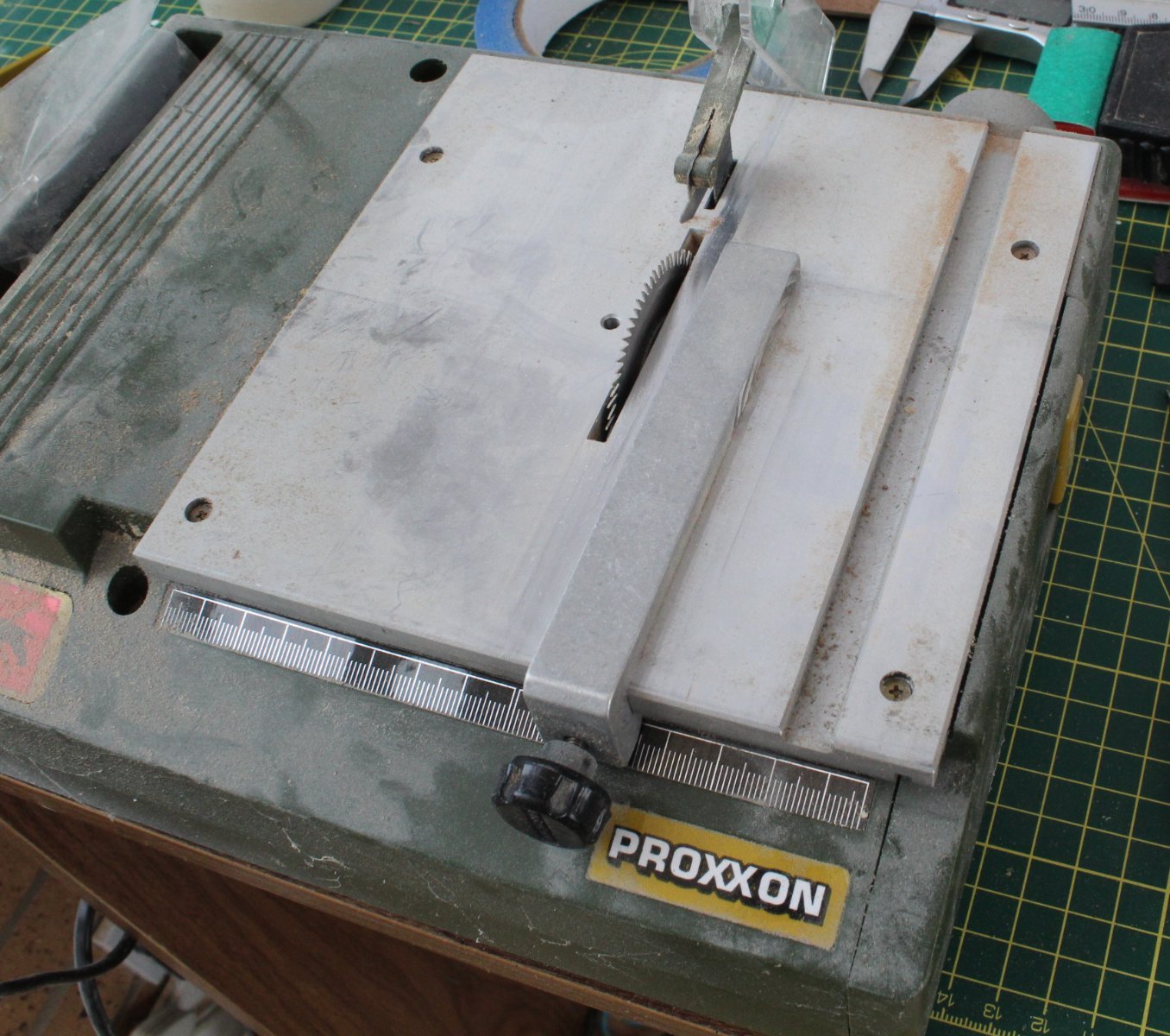
The lower foremast is made from a length of 10mm dowel. The upper section is 60mm long and comprises 55mm as a 7mm x 7mm square section and the top 5mm is set as diameter 7mm. My Proxoon circular saw was my tool of choice for this task.

I did have some 8mm x 8mm square material so I decided to use that to make the top section using the saw to trim 1mm from two sides. This can then be pinned in place on the 10mm dowel. Using the Proxxon saw set for a 1 mm cut I added the flats to the dowel for the two checks. I also added a flat for the front fish.

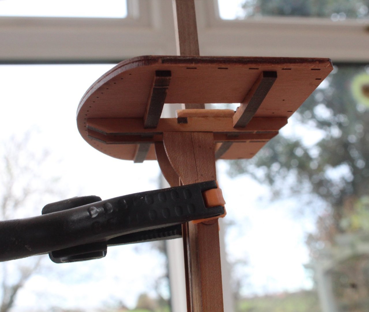
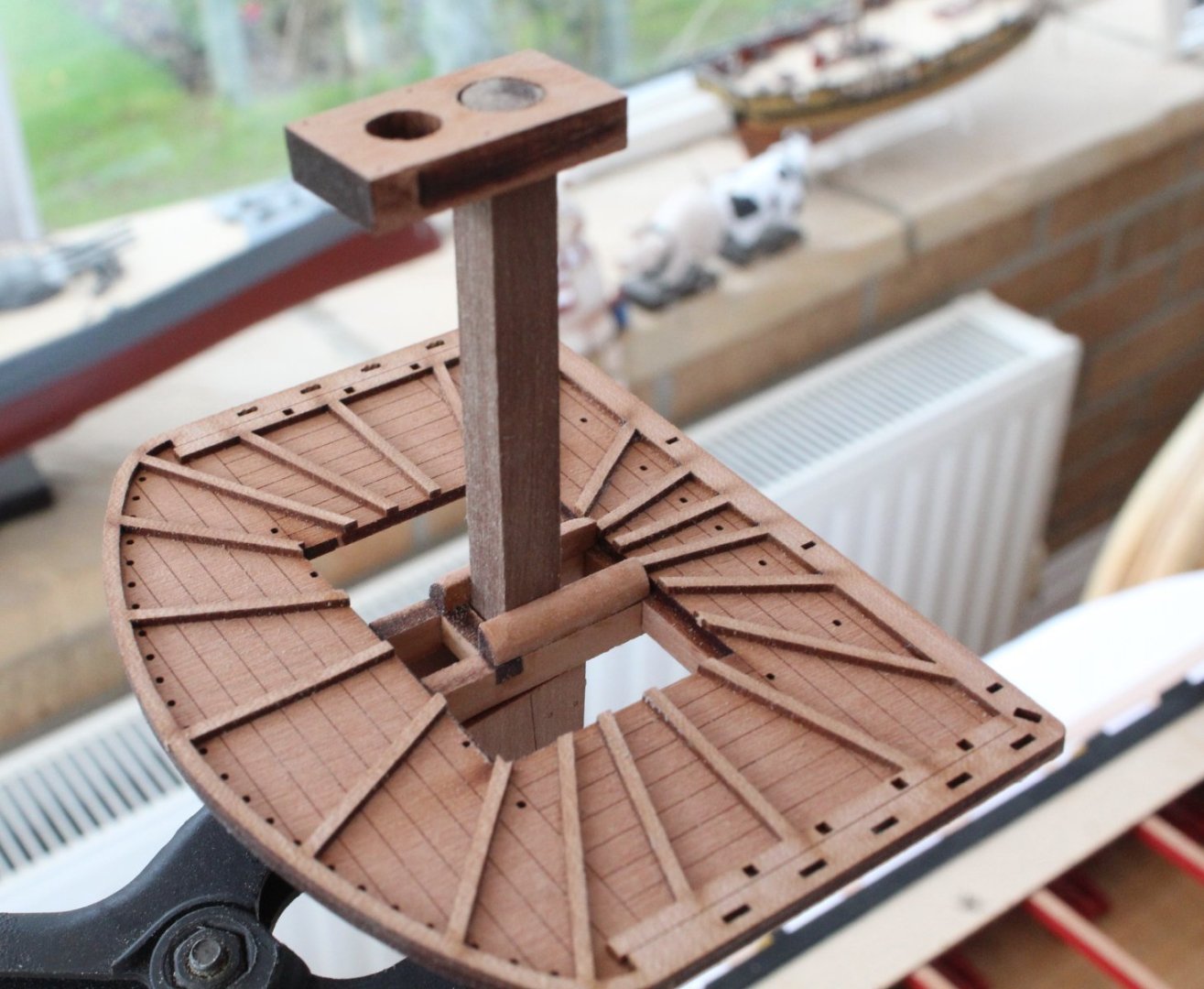
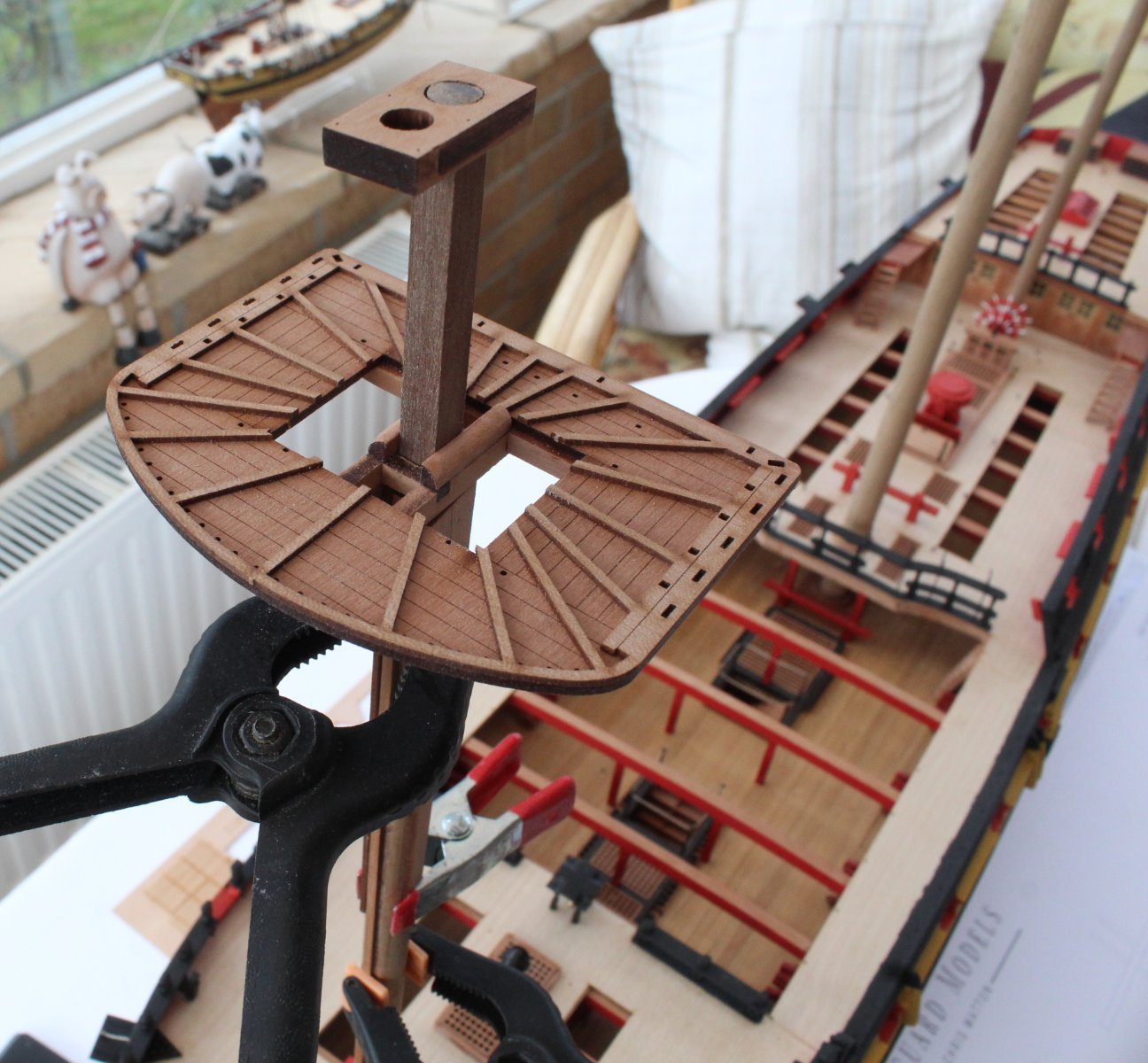
Before gluing the various parts in place I used some clamps to see how the lower foremast assembly would look in situ.
The square section is a good fit with the platform and with the cap

The front fish look good.

Bibbs also clamped in place
The top cap is a good fit also.
The black card iron bands needs to be added before the cheeks, bibbs and front fish are glued in place as the banding sits under these parts. My current thinking is to paint the mast yellow, then to add the black card iron bandings before adding the cheeks, bibbs and front fish.
However when looking at both @ECK and @Kevin build logs it would seem they fitted the simulated bandings after the foremast assembly and painting. I am assuming, if this is the case, that they only fitted the black card iron banding between the checks and front fish.
- scrubbyj427, Ronald-V, KARAVOKIRIS and 4 others
-
 7
7
-
Channel Update
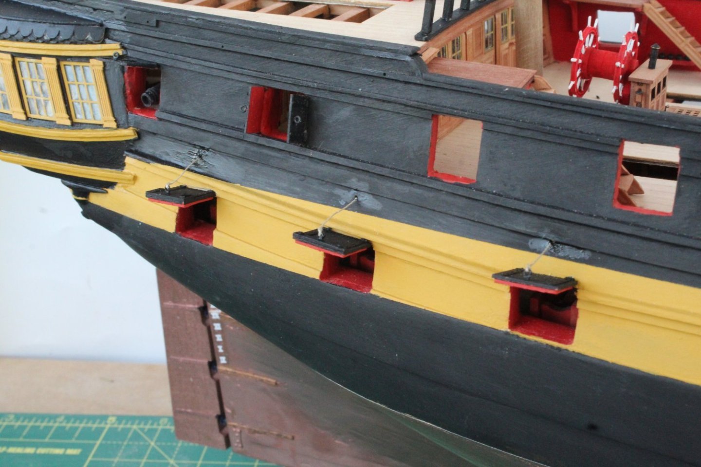
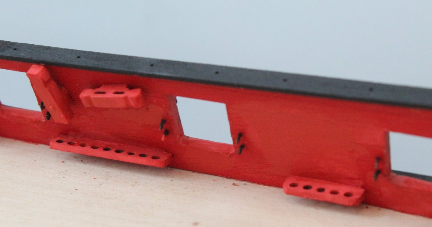
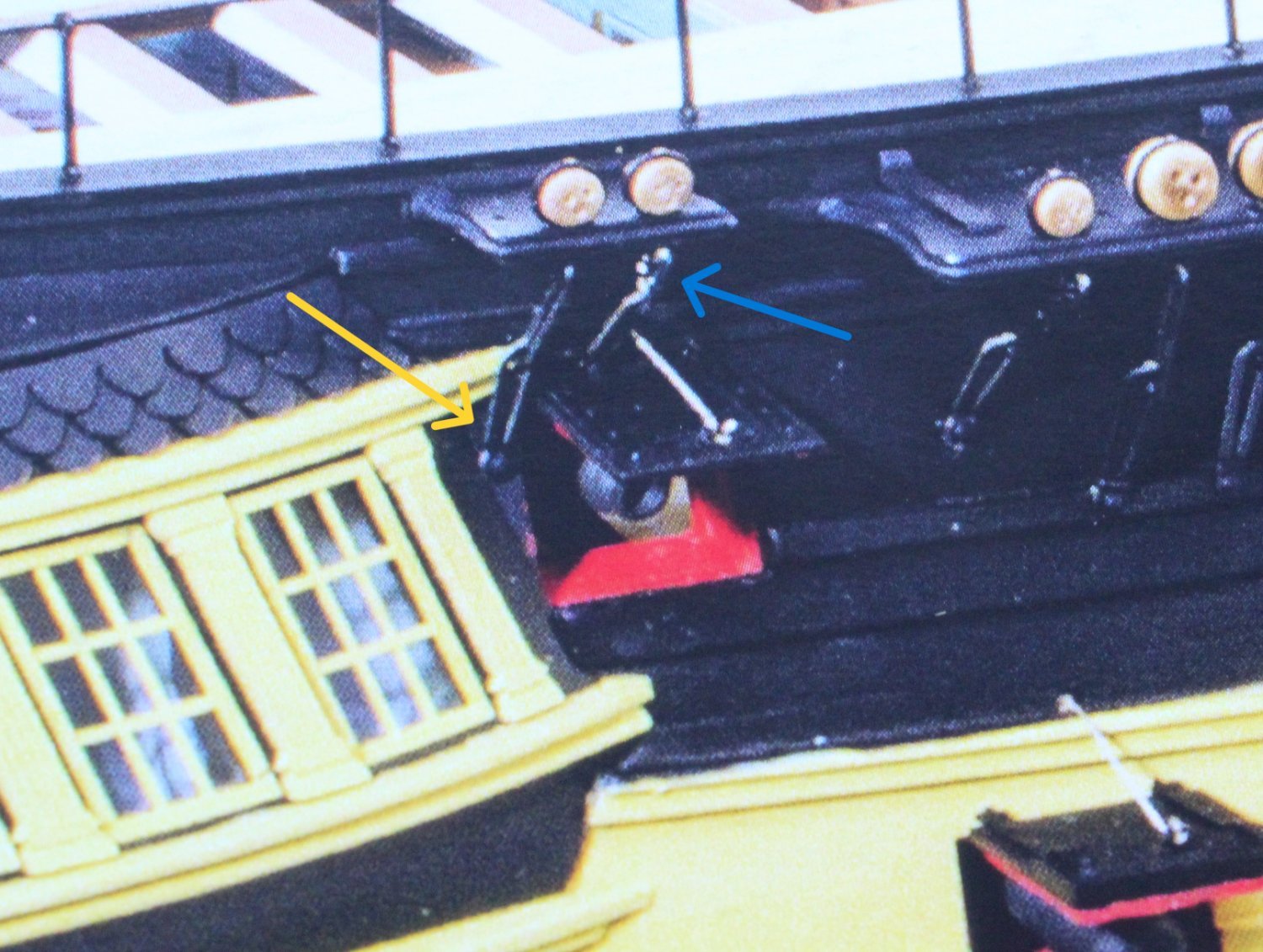
I have now experimented with adding a shortened middle chainplate for the rear most channel strop arrangement. With the shortened middle chainplate it will allow the lower chainplate to be fixed to the hull above the gunport.

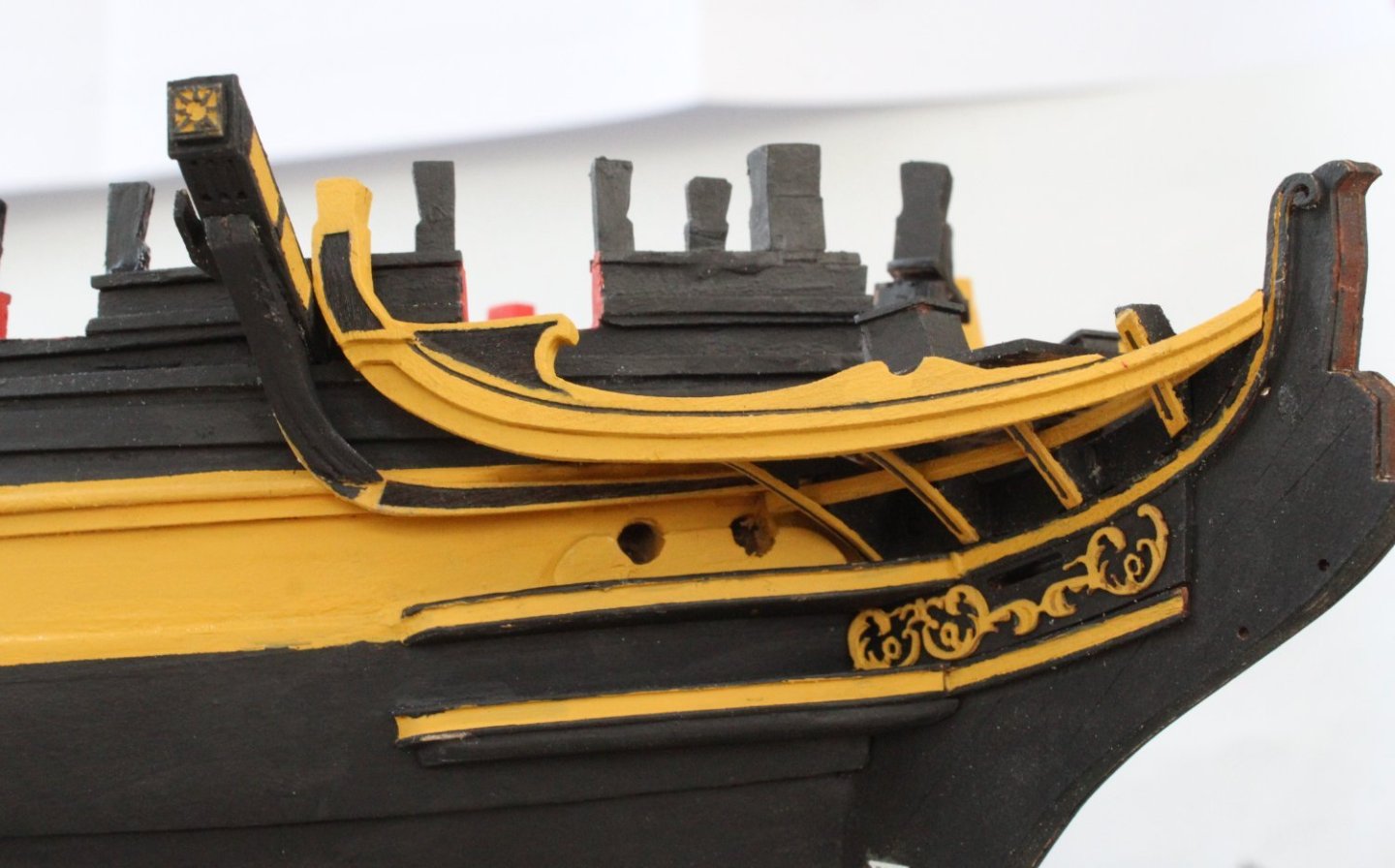
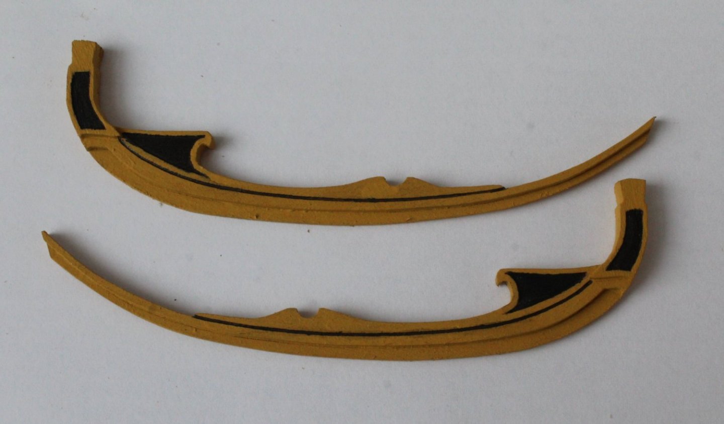
I have also be working on the foremast channel. I did add some additional material to the bow end of the channel to fill the gap that existed between the hull and the channel. I am now happy that the channel sits flush with the hull.
I am now going to turn may attention to making the lower fore, main and mizzen masts.
-
12 minutes ago, ECK said:
I choose that area as I found the angle and distance otherwise very tight. I found using the appropriate dowel in the mast hole and string gave a pretty good angle for the chains. I 'll find out how well next week when I start doing the shrouds.
I was thinking the same but I am going to make some shortened middle chainplate links to see what looks best.
-
7 minutes ago, RossR said:
Thanks for sharing you thought process on this step. I am at a similar point in my Frigate Diana build and you validated some of my decisions. I am fabricating my chain plate out of black annealed wire as my kit suggested using a single strand of brass wire. I didn’t like that approach. spent quite a bit of time making different sized pieces trying to find the right combination of components to fit right.
Your work is fantastic. I hope one day my work will look this good.
Many thanks for your comments, it is much appreciated. Experience has taught me to take my time with this aspect. Once I have sorted out the foremast channel aligment issues I will construct the masts.
-
Channel work and thoughts
This is no a build progress post, it is my just detailing some of my thought processes.
When fitting the channels I think it looks nice if the chainplate links follow the flow / direction of their respective shroud lines. Therefore I find it is better to build the masts before fitting the chainplate links so that each shroud line flow can be determined.
Also when looking at the chainplate links and strops arrangements for the Indy I am more inclined to fit the chainplates to the deadeye strops before the channels are added to the hull as I think it will easier to do that than after the channels have been fitted to the hull.
This means that my next build stage will be the production of the fore, main and mizzen masts.
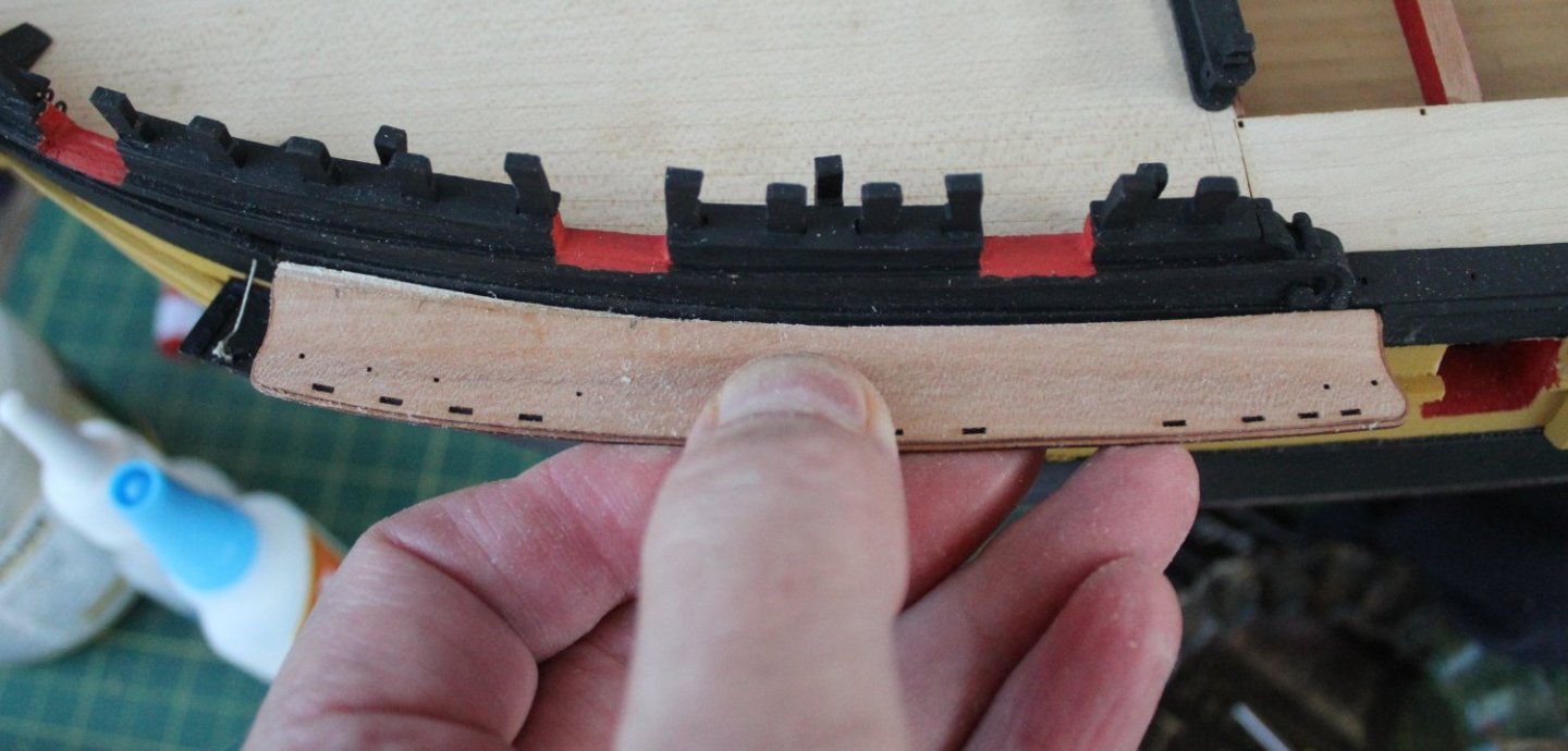
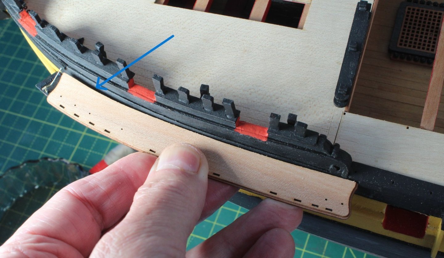
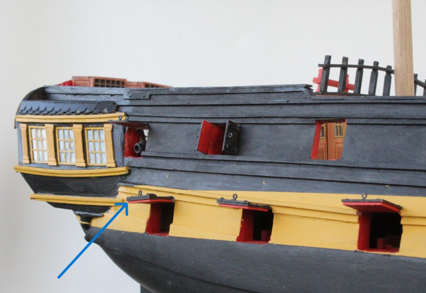
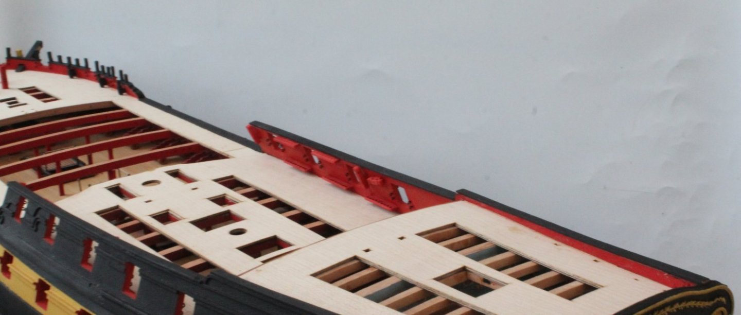
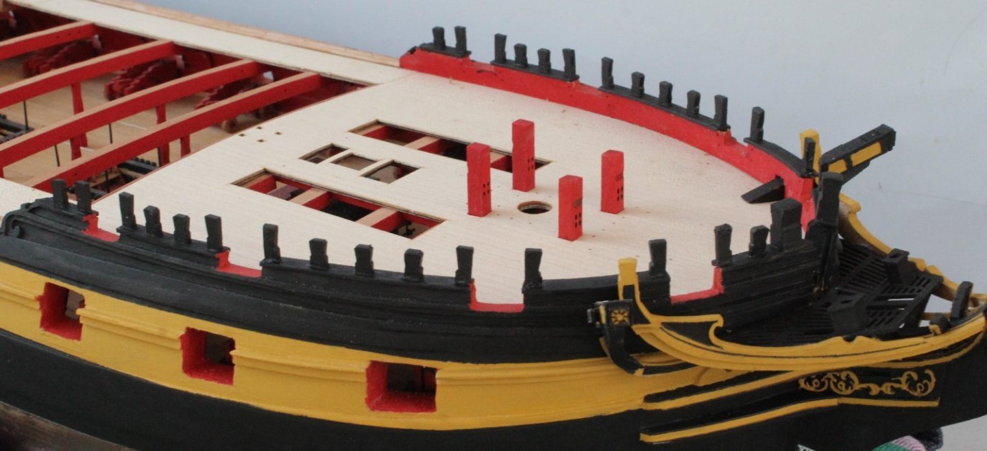
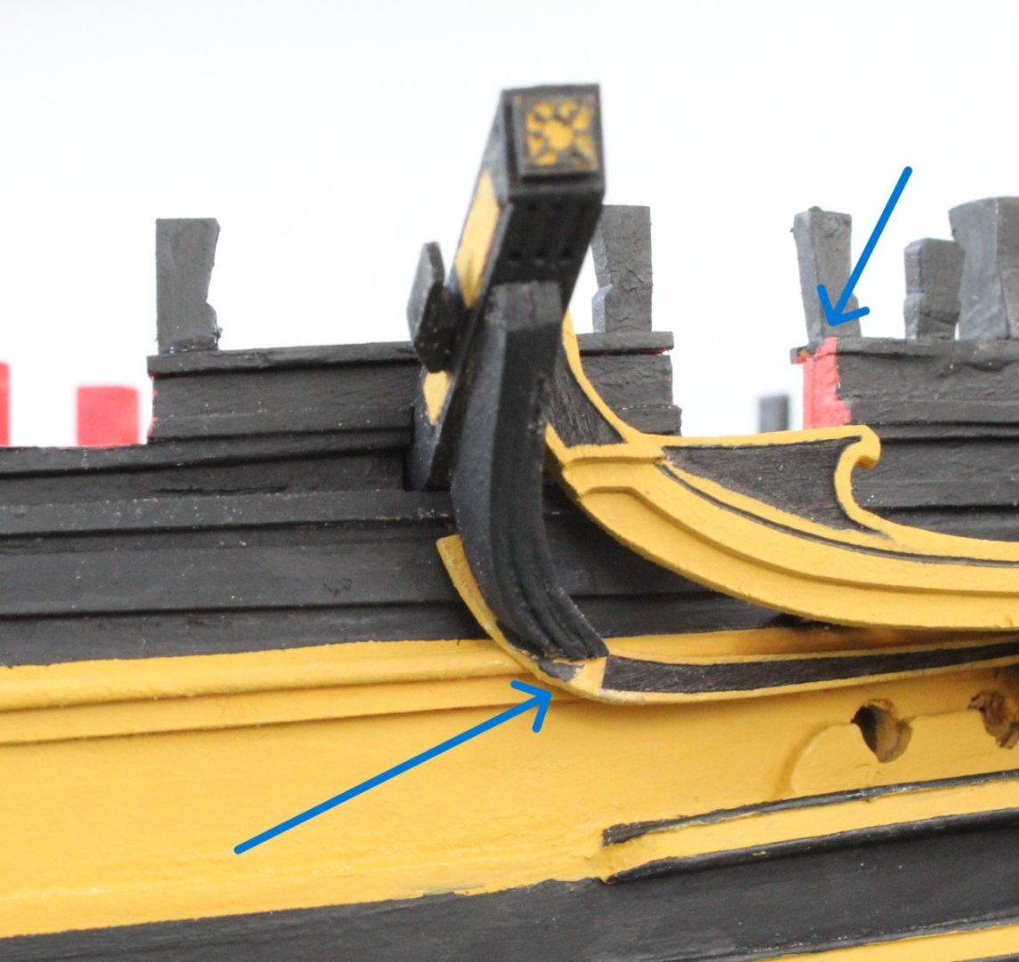
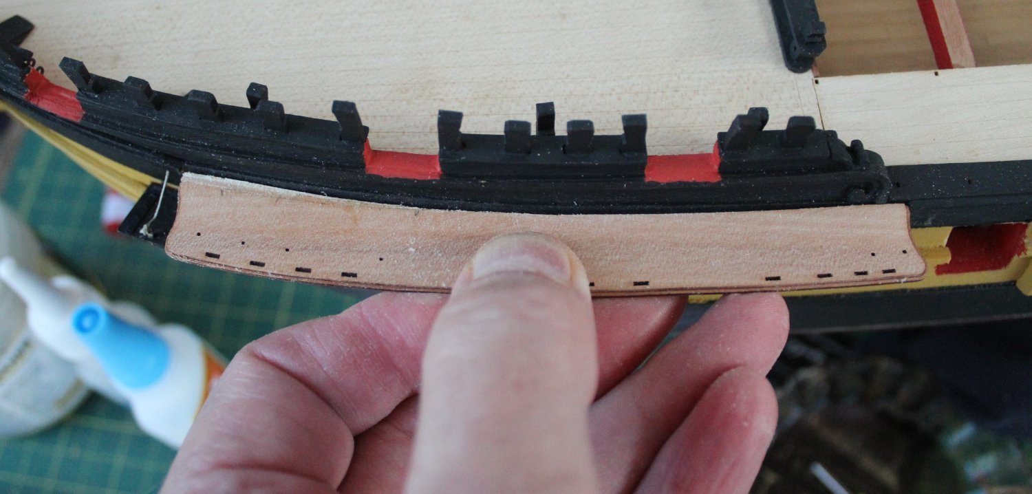
However before starting work on the masts I decided to spend a bit of time checking the fit of the channels to the hull. Everything looks good except the channel for the foremast. As can be seen when the channel is offer up to the hull there is a gap, as indicated by the blue arrow. I will need to sort this out before moving on to building the masts.
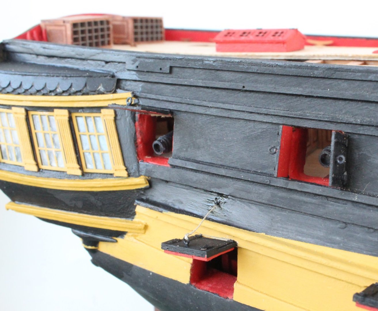
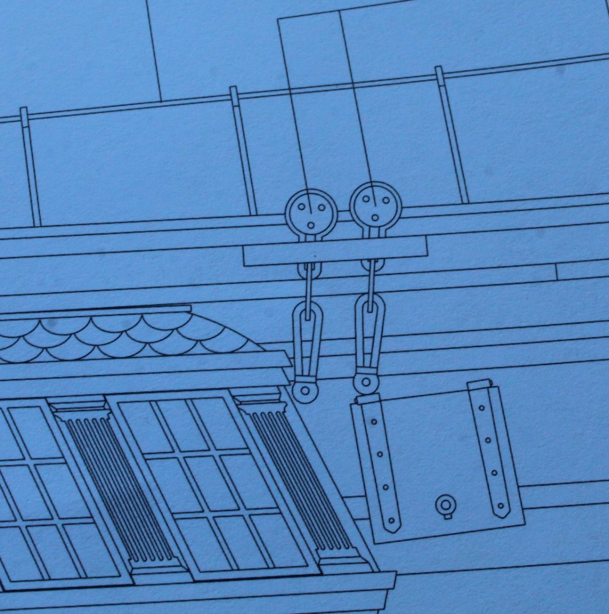
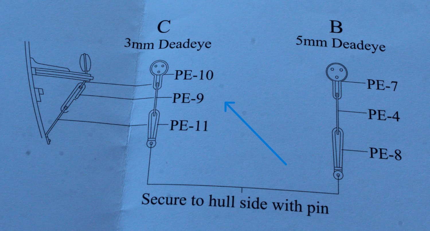
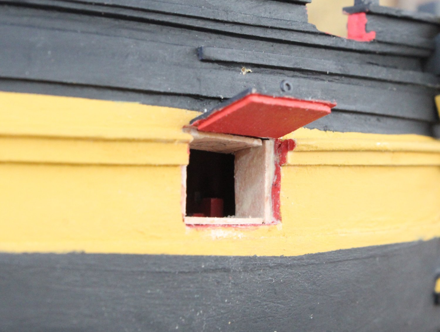
I did not fit one of the gunport lids as I was a bit concerned with it interfering with the fitting of the chainplate to the rear most channel. According to the admiralty plans (shown below) this should not be an issue as they will be terminated above the gun port.
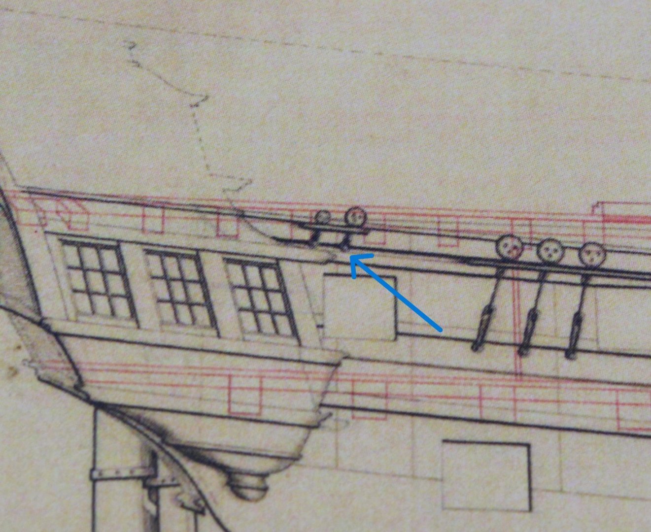
When looking at the kits plan sheets this also seem to be the case. So far so good.

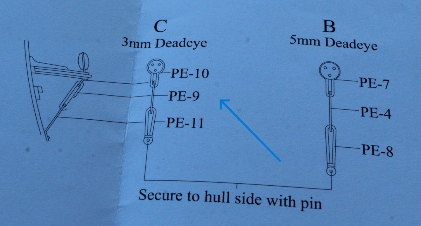
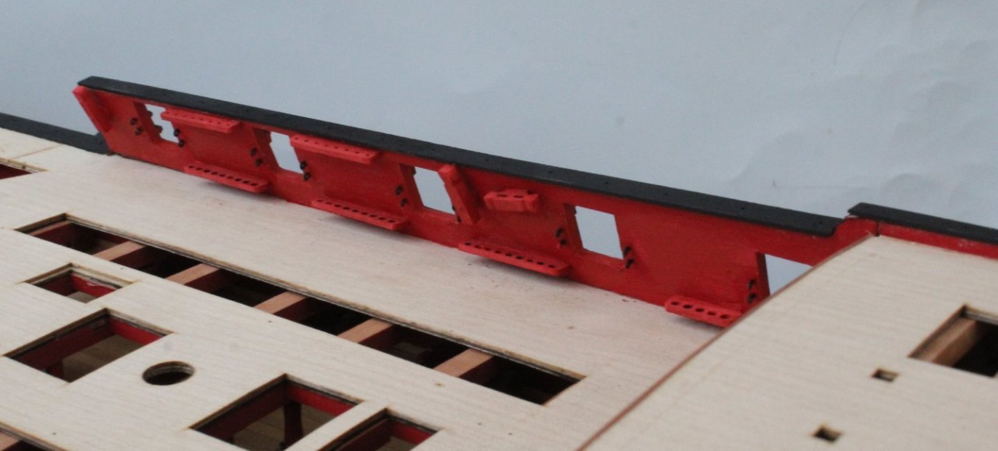
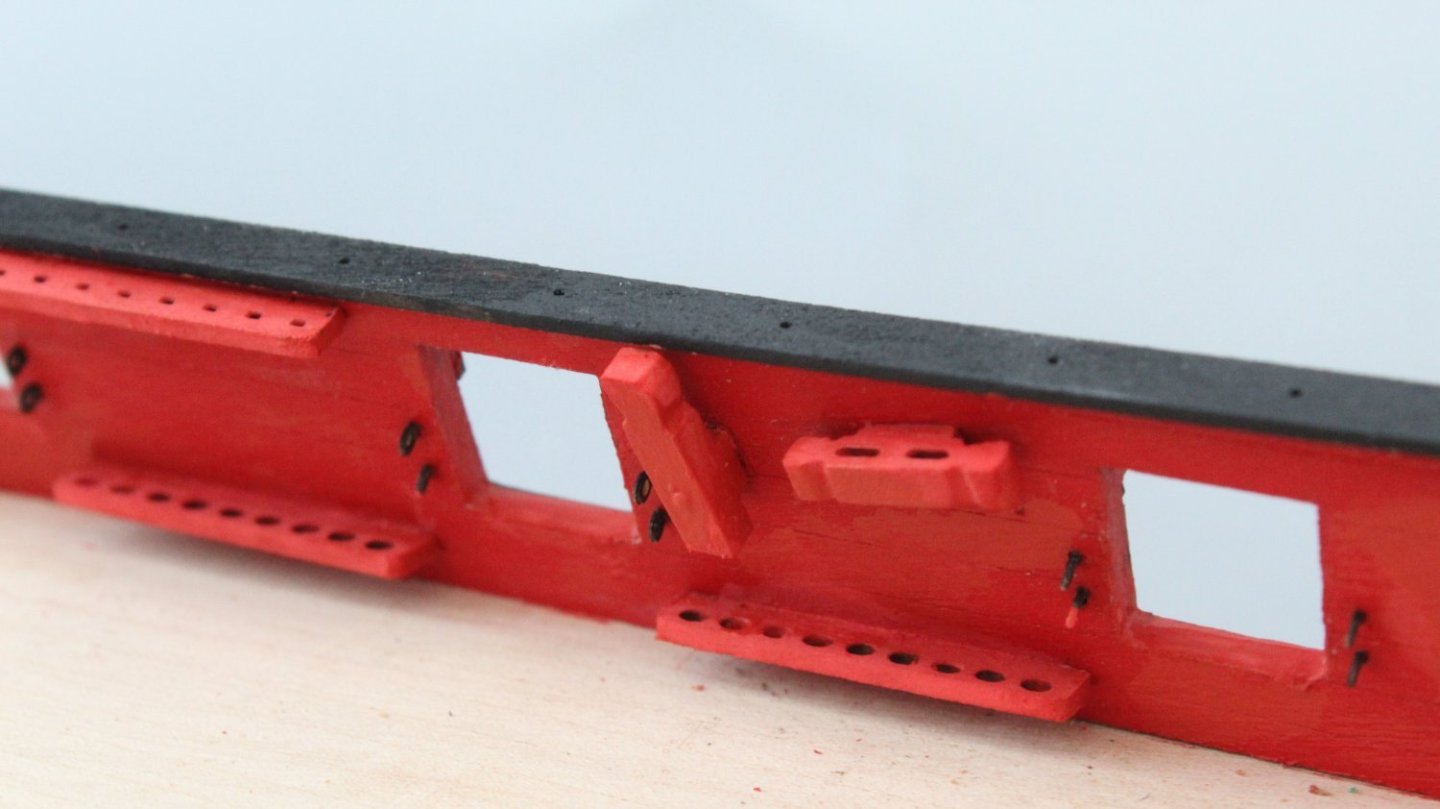
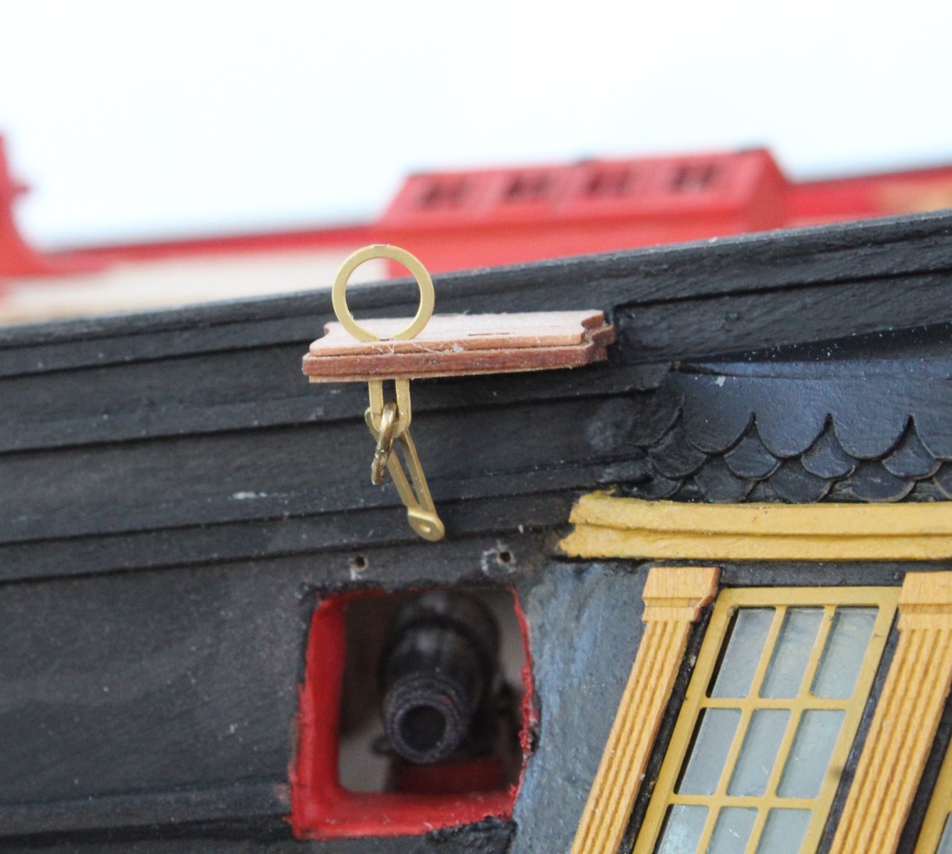
Next I looked at the assembly requirements which is shown as a type C arrangement with two chainplate links (PE9 and PE11).
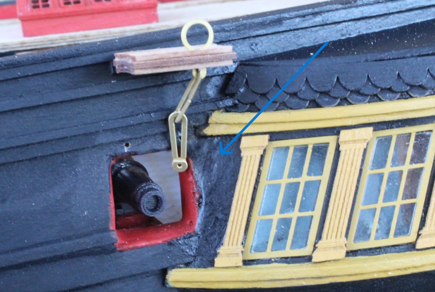
With a test fit (as shown below) the chainplates will terminate below the level of the gunport. I noticed that ECK terminated both chainplates in the area indicated by the blue arrow.

When looking at the prototype build it would appear that Jim fitted one to side and then added a shortened middle link, as indicated by the blue arrow.
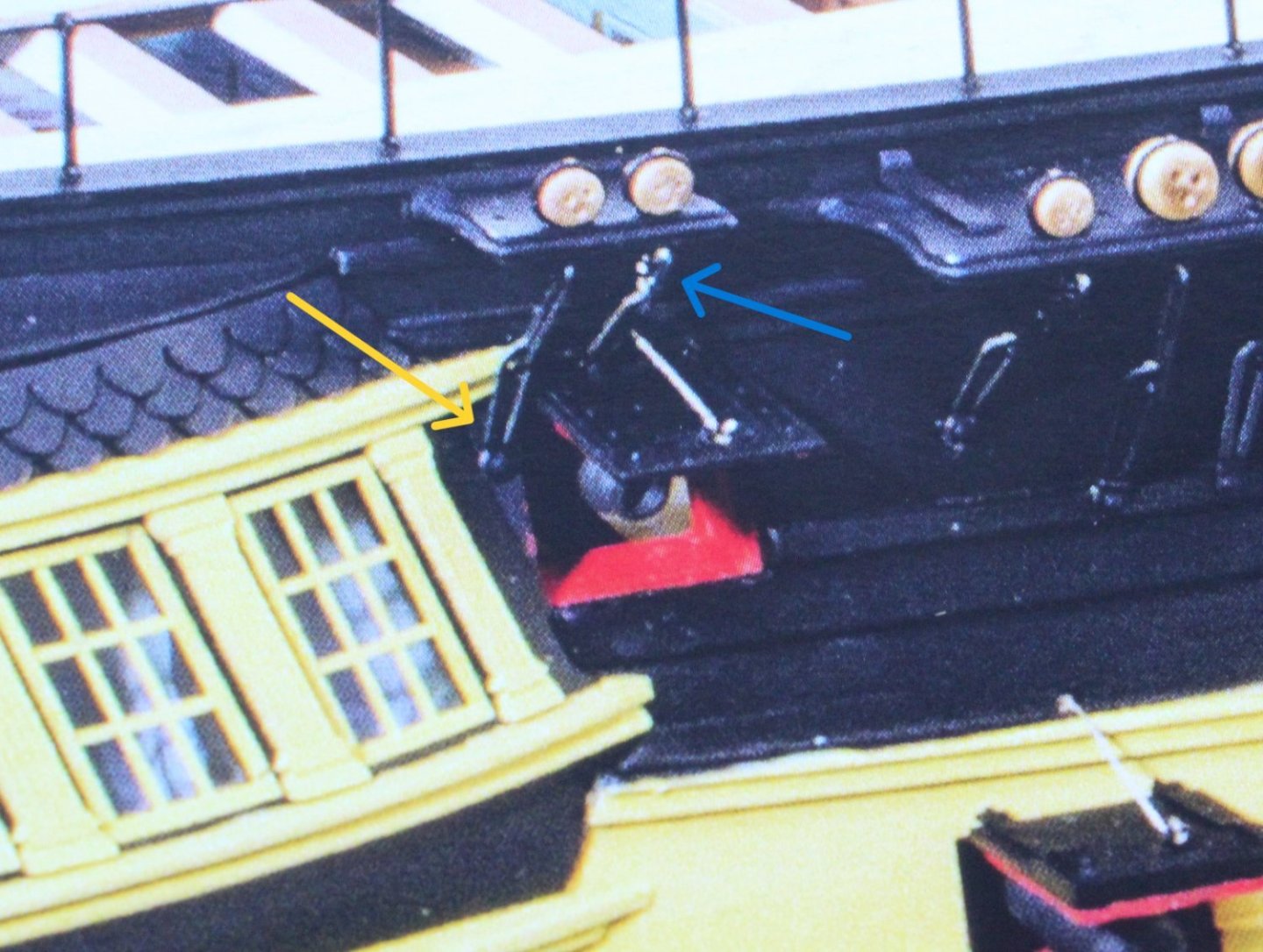
I more inclined toward a shortened middle link solution.
- davyboy, AJohnson, KARAVOKIRIS and 7 others
-
10
-
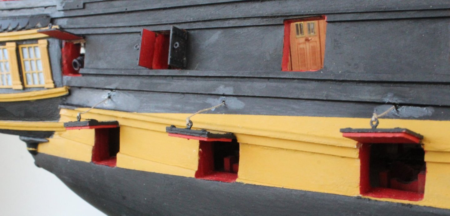
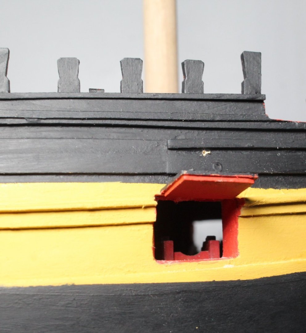
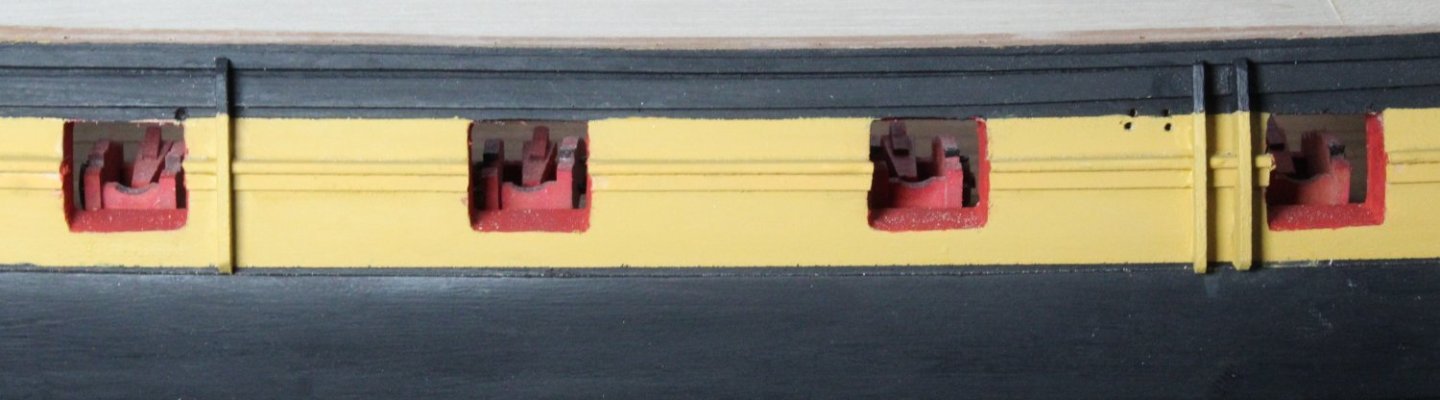
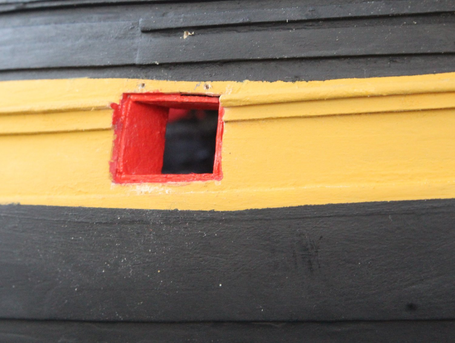
Gun Port Lid Installation
Following on from my last post I continued the work with installing the gun port lids by adding the linings to the bow gun port.

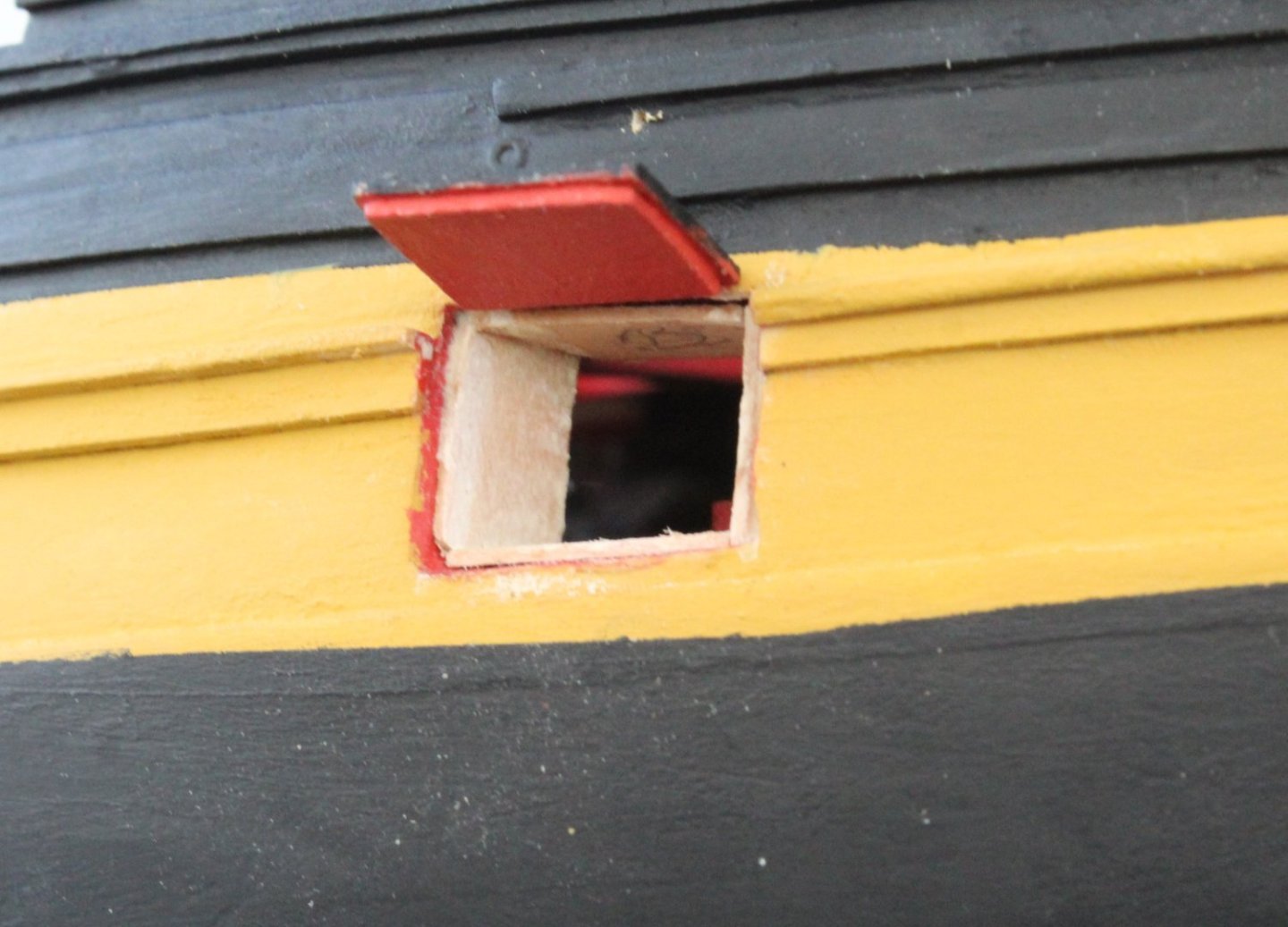
The linings needed to be painted red.

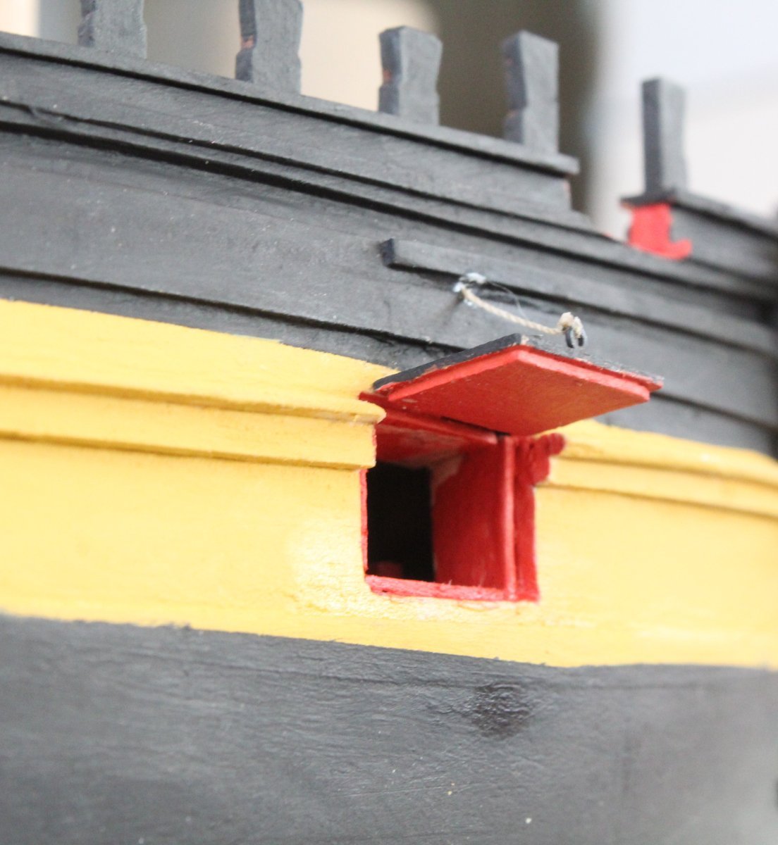
The bow gun port complete with lid

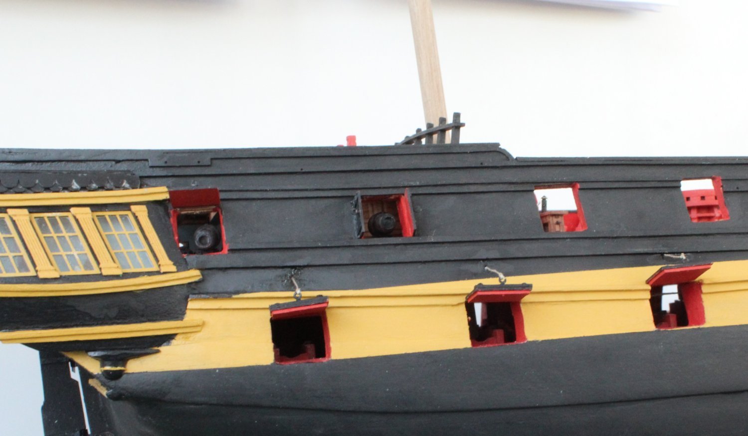
The stern gun port lids were test fitted. One gun port lid looks wonky in the first photo (blue arrow), not sure why.
The installation is now complete. I did touch up some of the black paint which was still wet when I took the following photos.
The top left hand gun port lid has not been glued in place as I will remove it whilst I add the small channel, strops and chain links which is located above it.

-
-
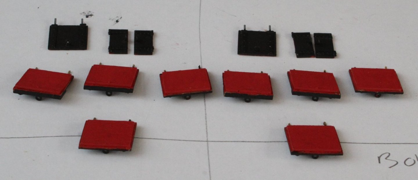
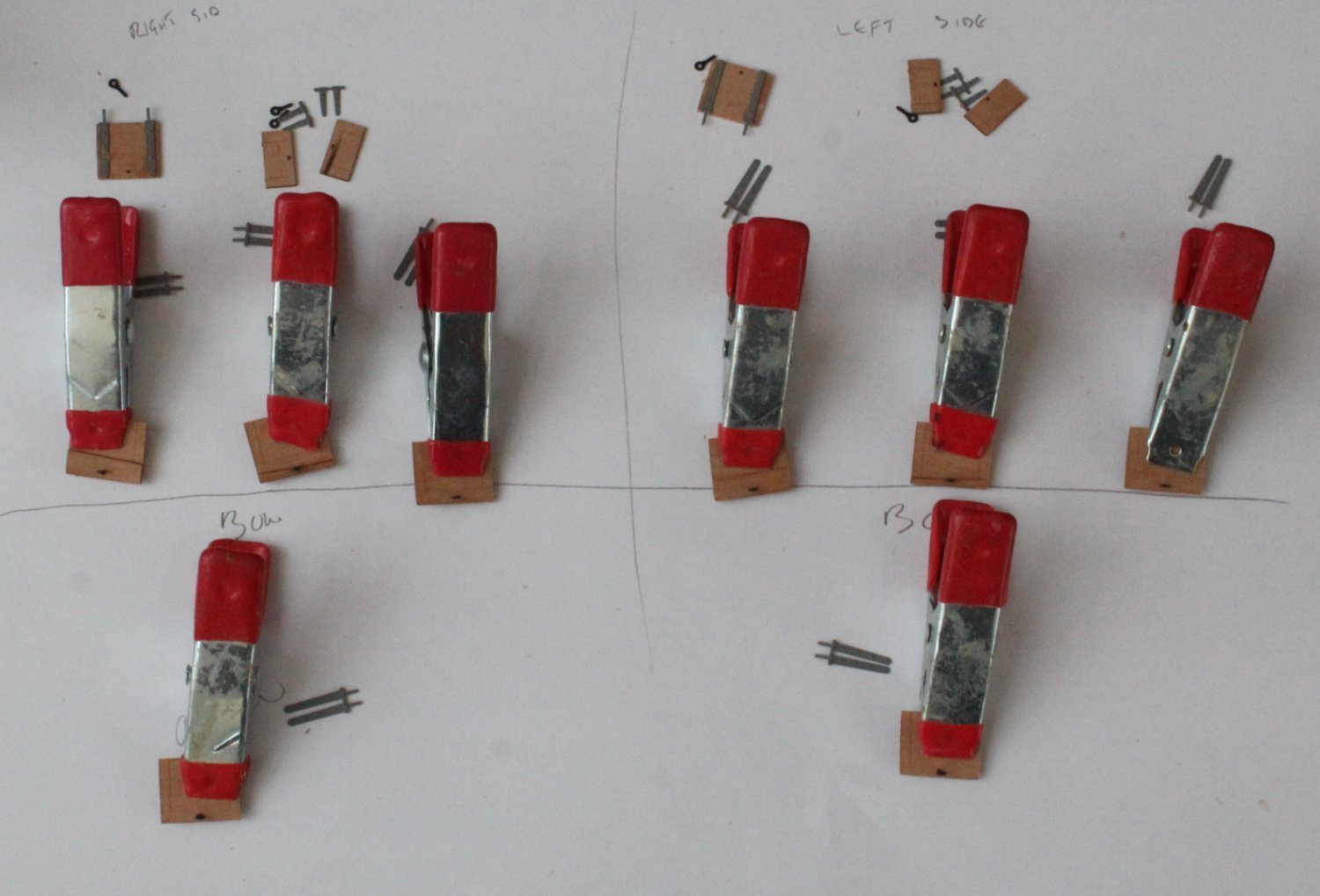
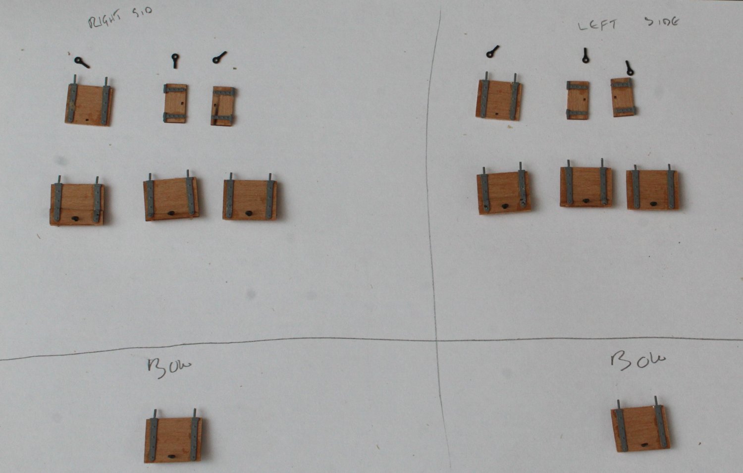
Gun Port Lid Assembly
Today I started work on the gun port lids. There are 6 gun ports per side which will have lids.
The first task was to collect all the various parts, which was a mixture of wooden and PE parts. The various lids were placed in their respective hull positions to ensure I built them up correctly.
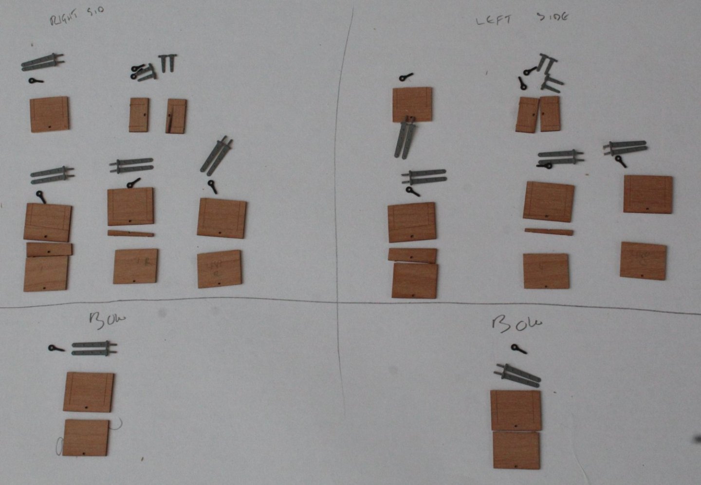
Using the eyebolts as an alignment guide the various wooden parts were glued and clamped.

The next task was to add the hinges.
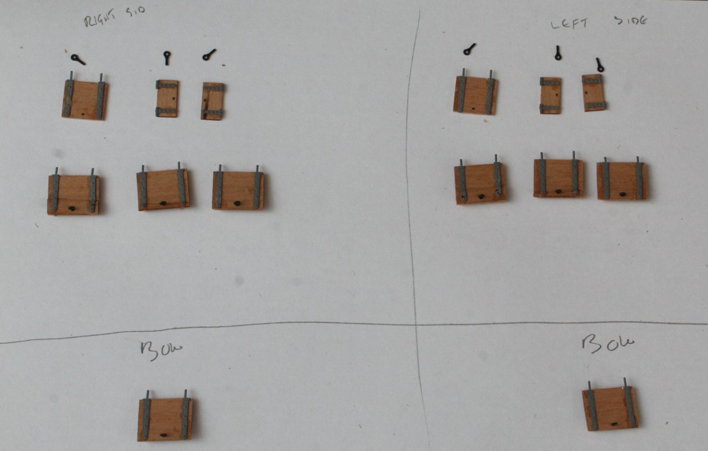
Once the eyebolts were glued in place the gun port lids were painted, red for the inner surface and black for the outer surface.
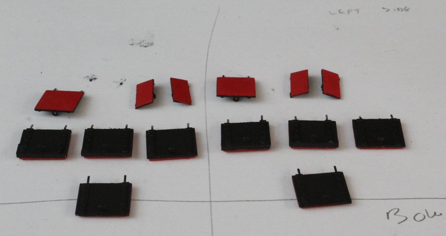
The next task will be to fit the lids to their respective gun ports. Starting with the right-hand side bow gun port I drilled the holes, in the hull, for the hinges and the thread. I took a couple of pictures with the gun port lid dry fitted. I noted that actual gun port opening was wider than the gun port lid and I then realised that I did not add the kit supplied gun port linings so I will need to add them.

-
-
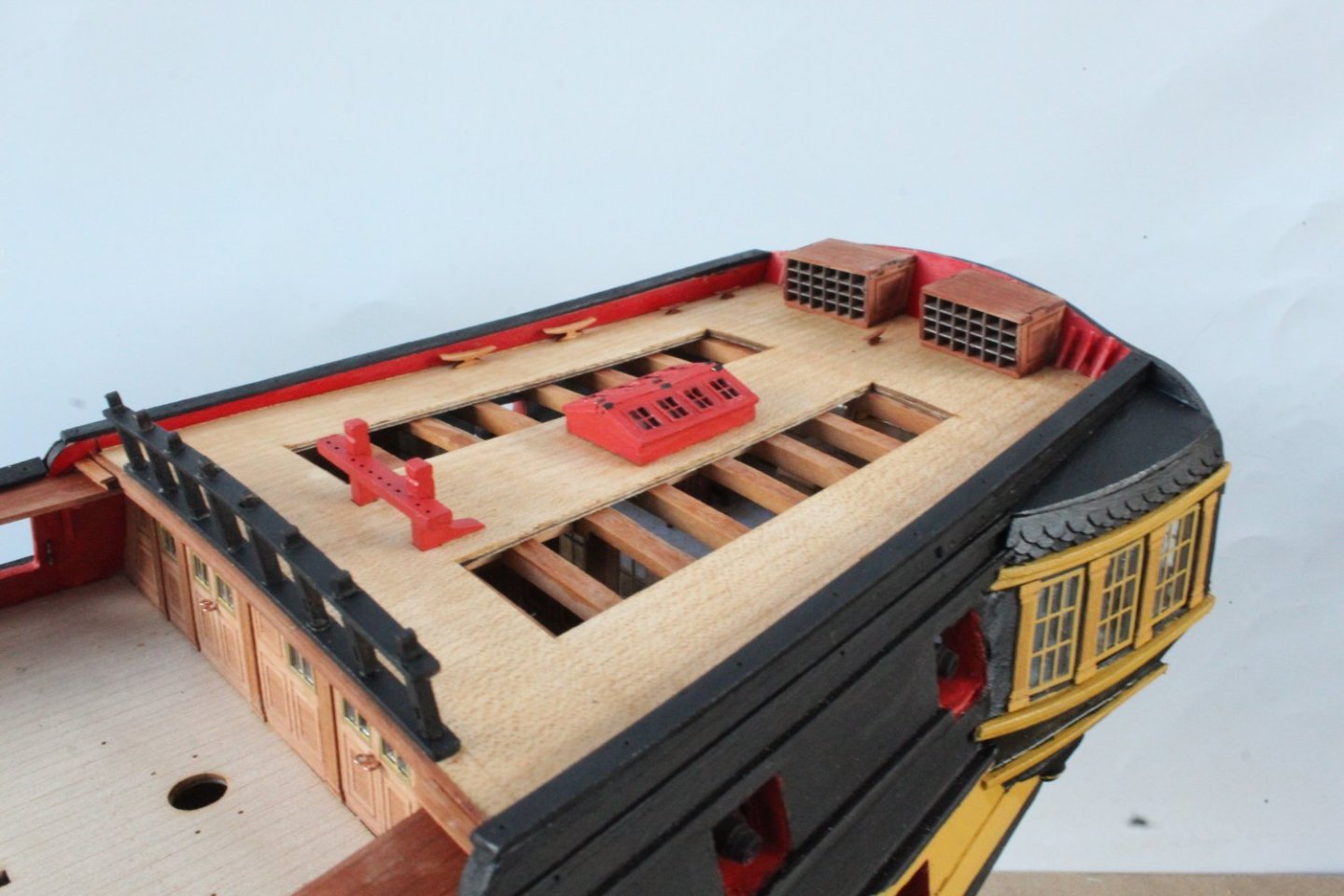
Deck Work Completed
I had a really good day in the shipyard and made much more progress than I was expecting.
I have now completed adding all the various deck items.
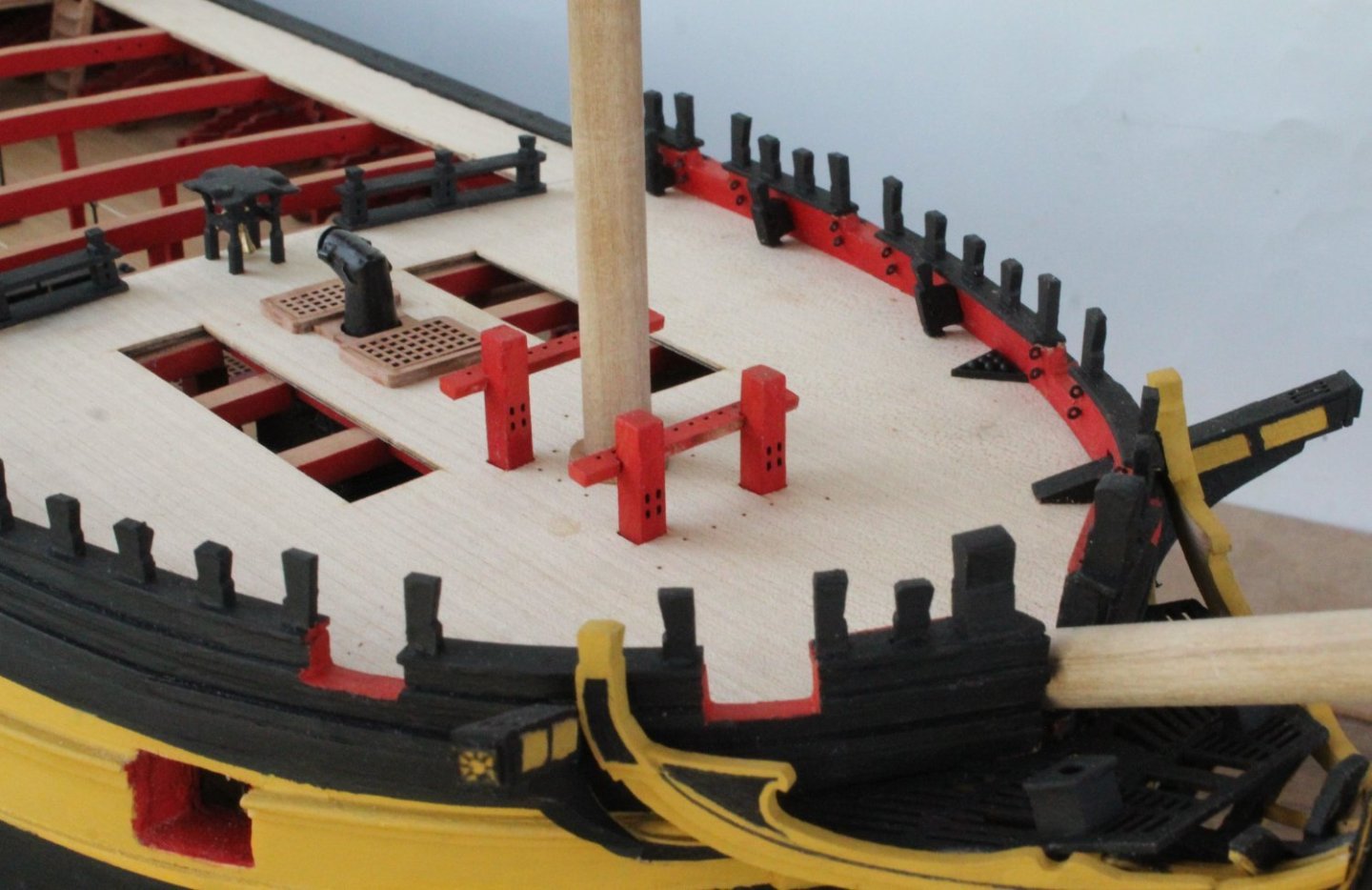
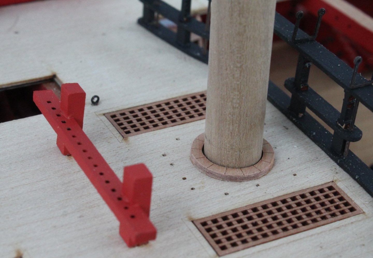
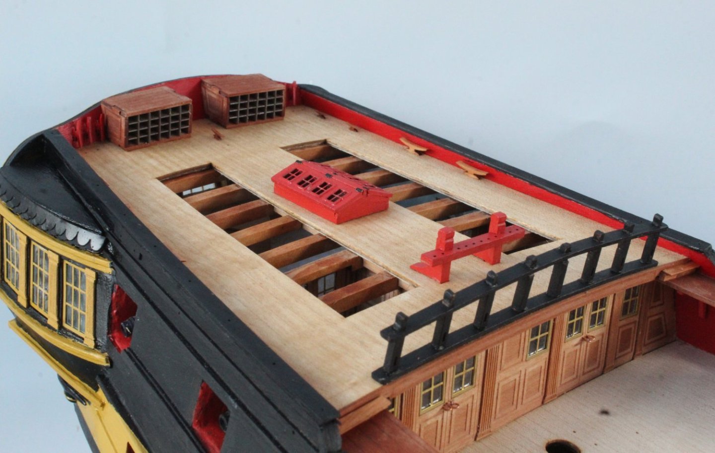
Forecastle Photos
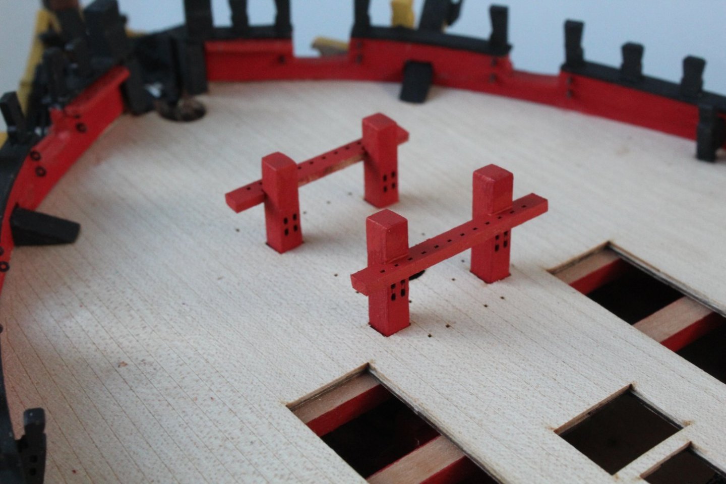
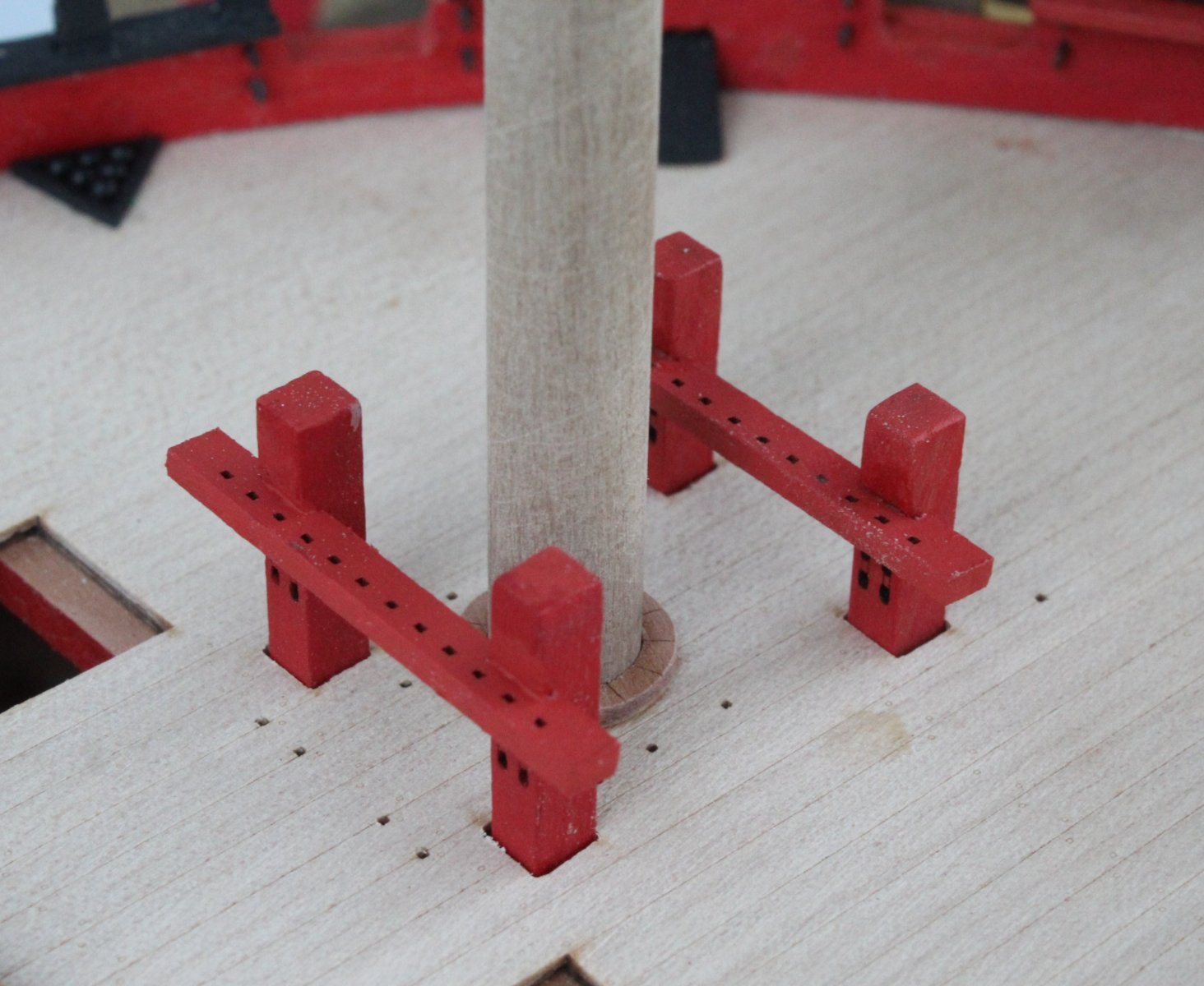
Bitts, after the forward belaying rack was reposition. The foremast ring has also been added with the foremast test fitted.

Shot garlands
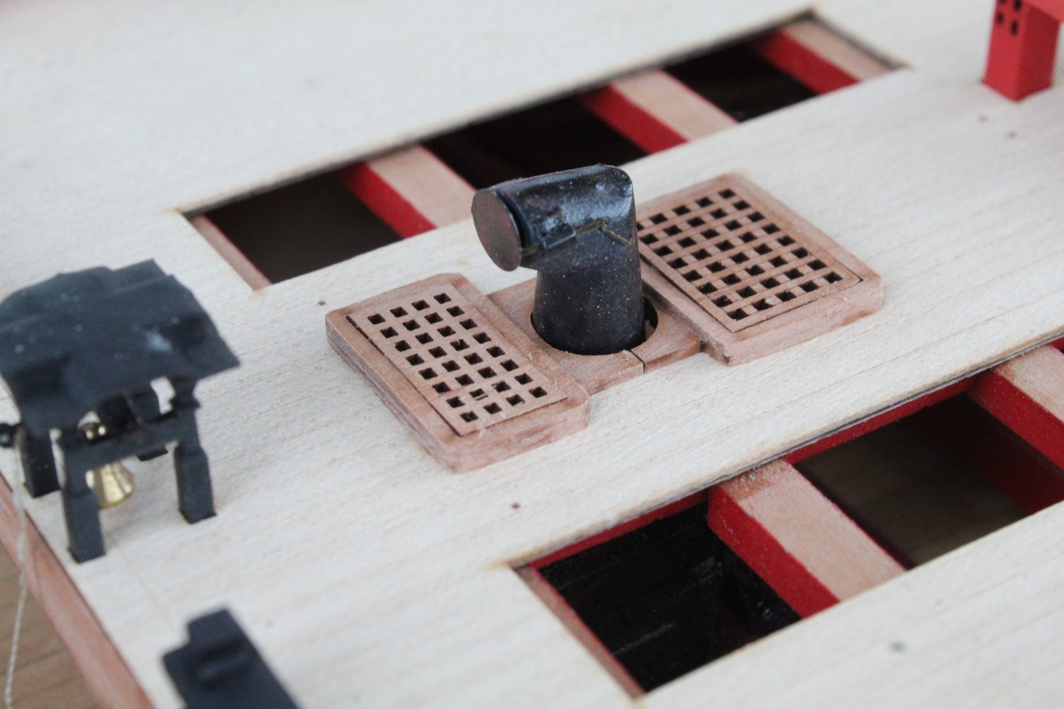
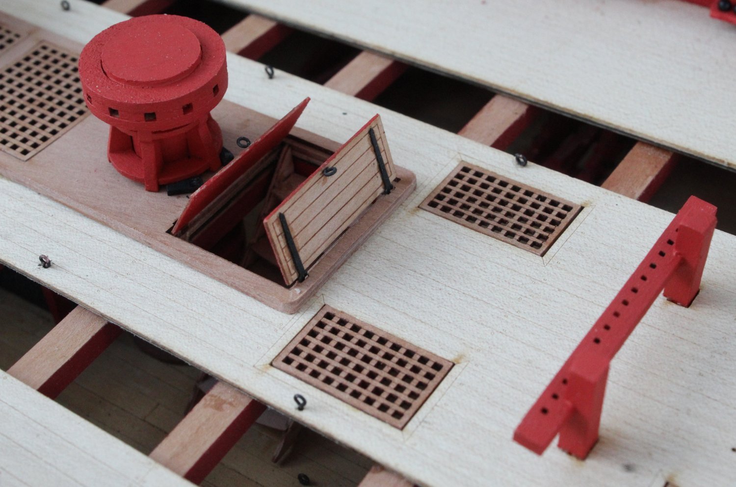
Stove and hatch covers

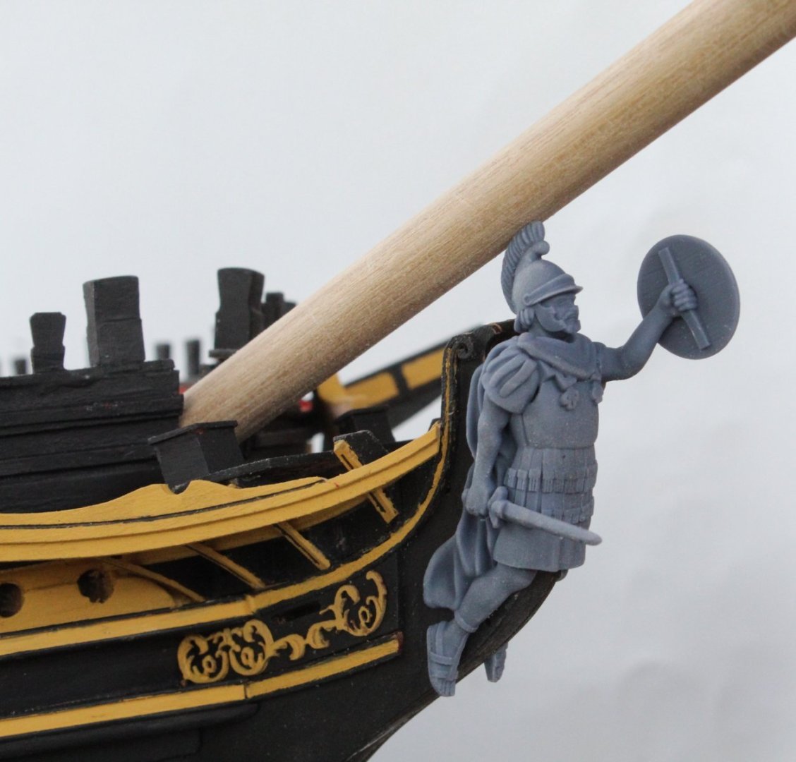
Figurehead test fit. I'm not sure why the figurehead's toes away below the stem post and will require a little bit of detective work.
Forecastle Deck
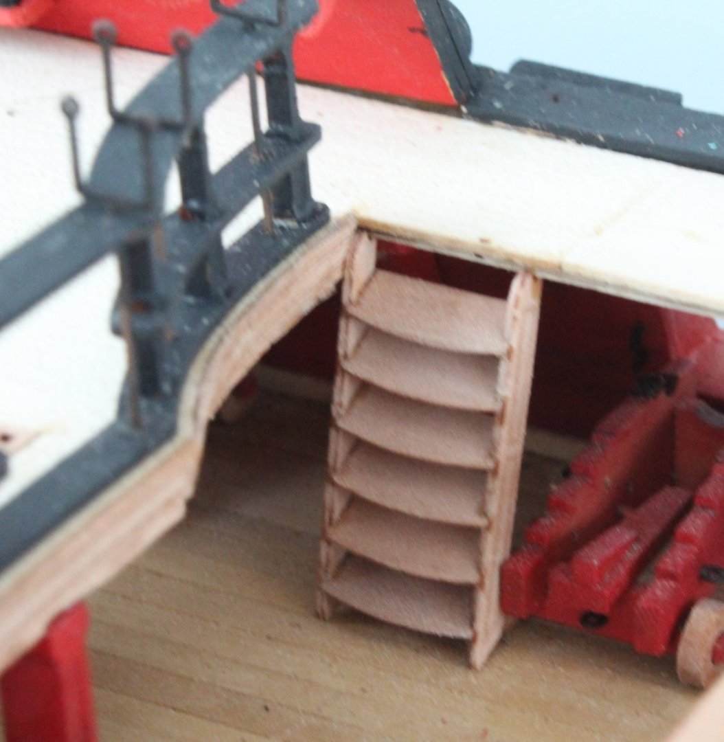
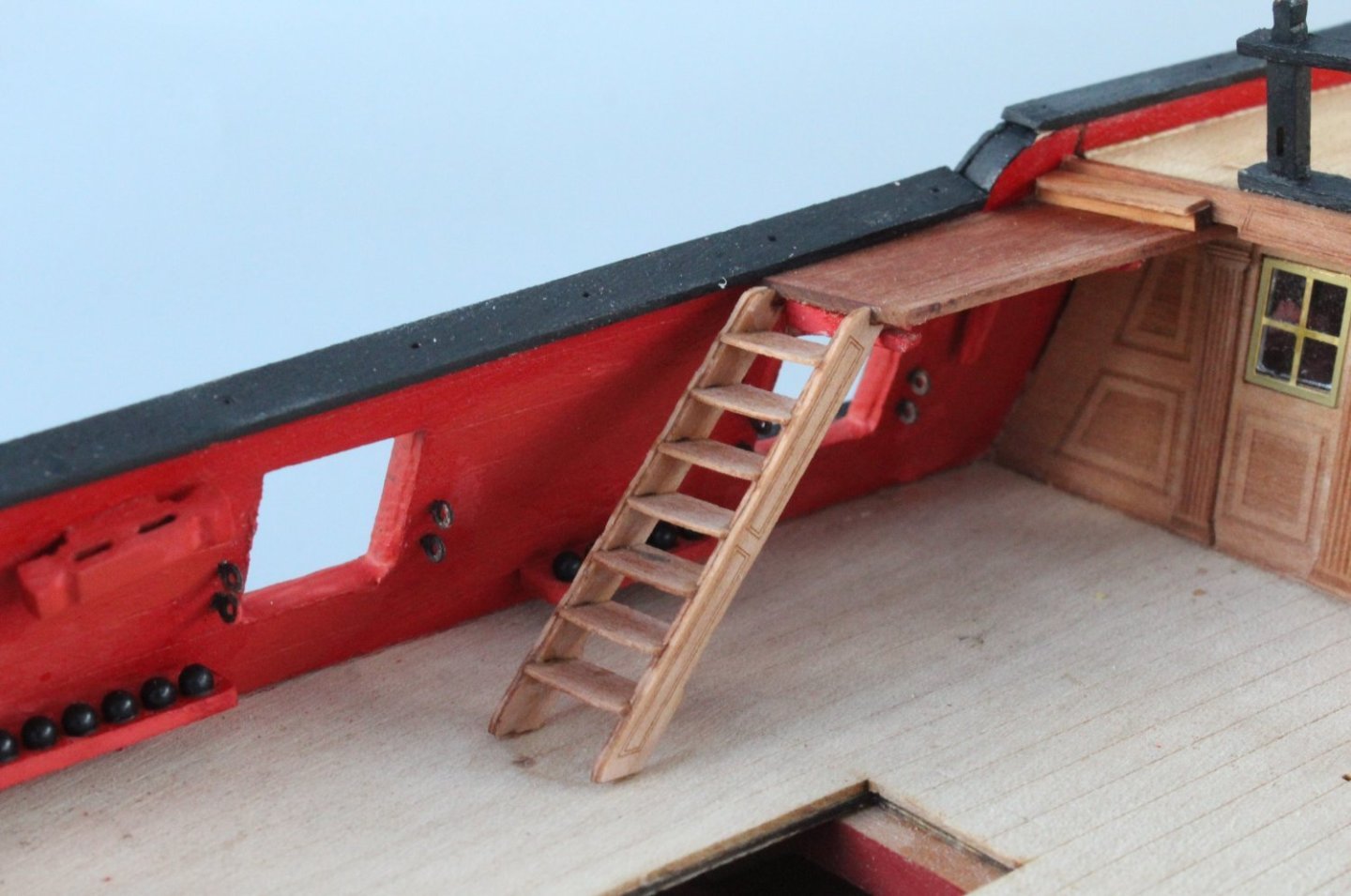
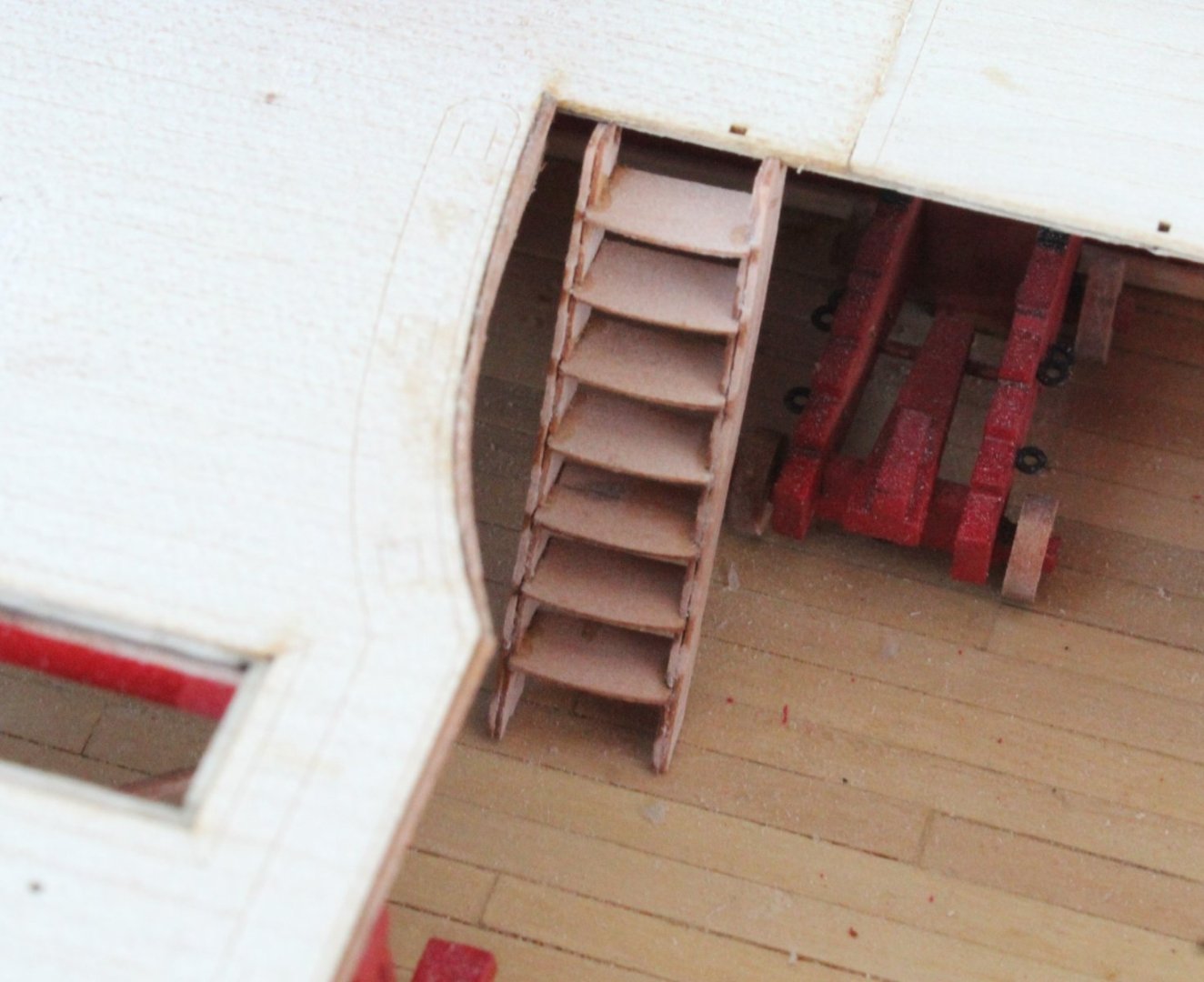
Gangway Photo
A nicely out of focus photo. It took several attempt to fit these ladders and this was the best fit I could achieve.
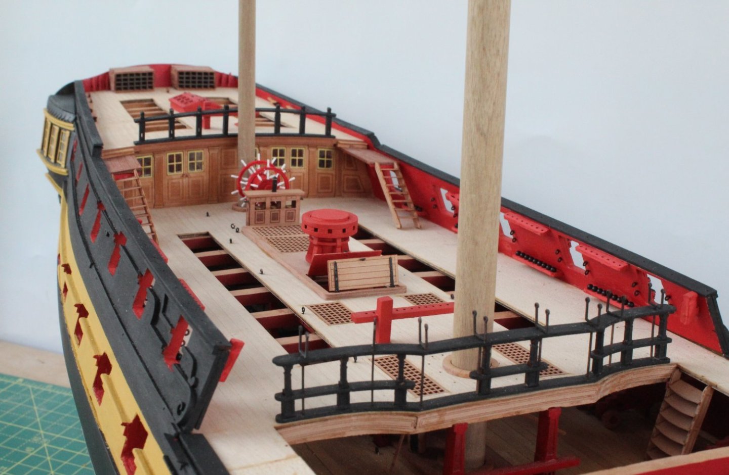
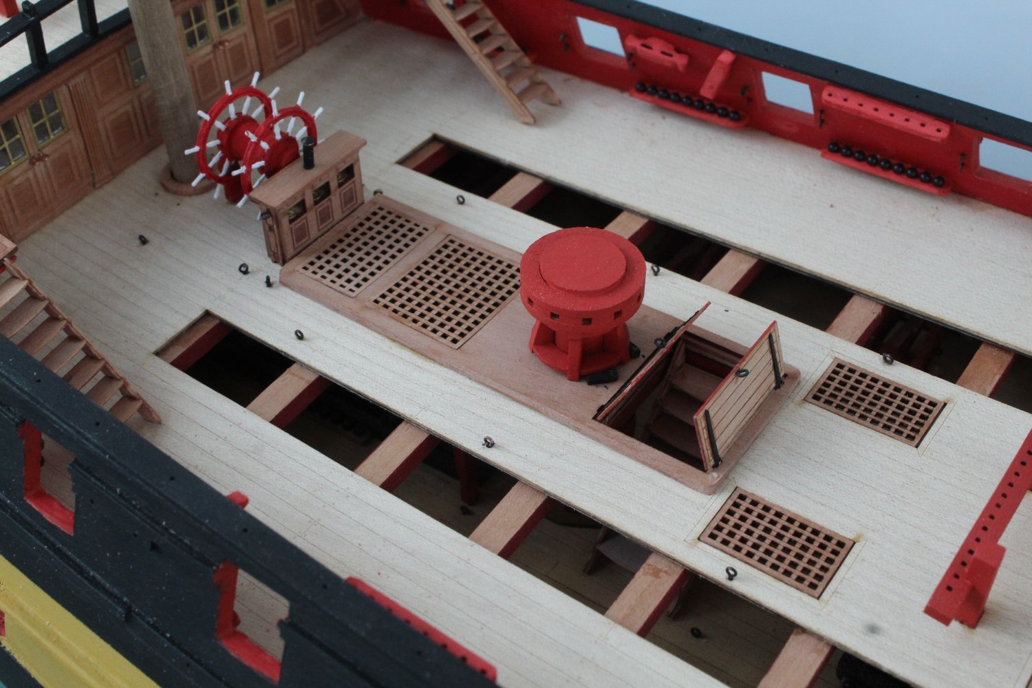
Quarterdeck Photos
Main mast ring, bitts and hatch covers
Hinged hatch covers and capstan

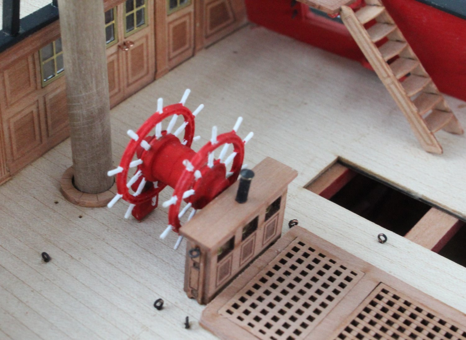
Binnacle, ships wheel and mizzen mast ring. I might add some rigging for the binnacle.


Quarterdeck

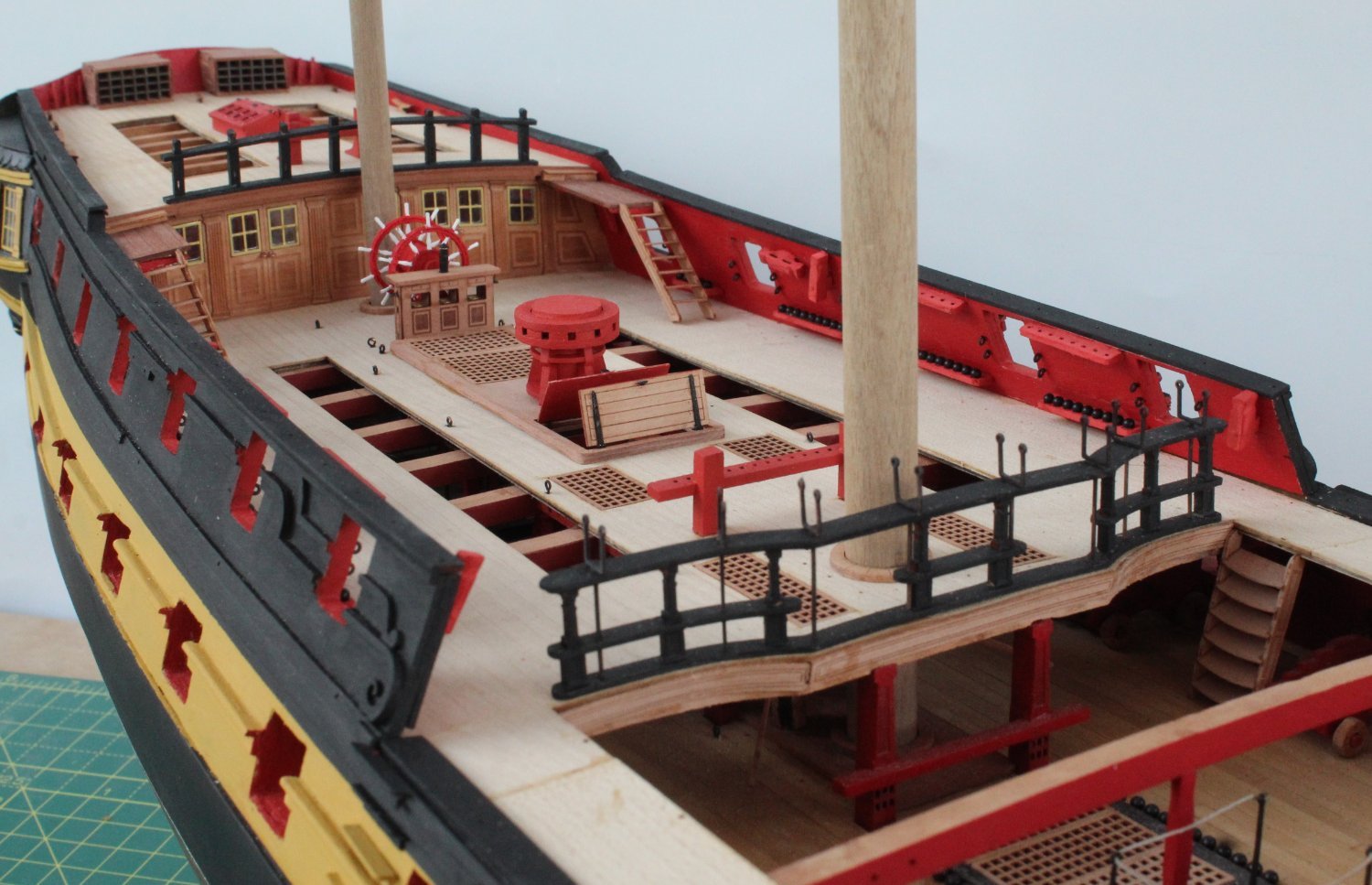
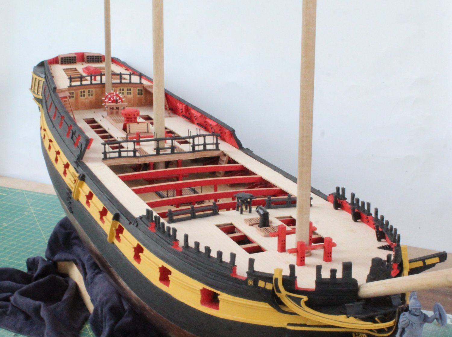
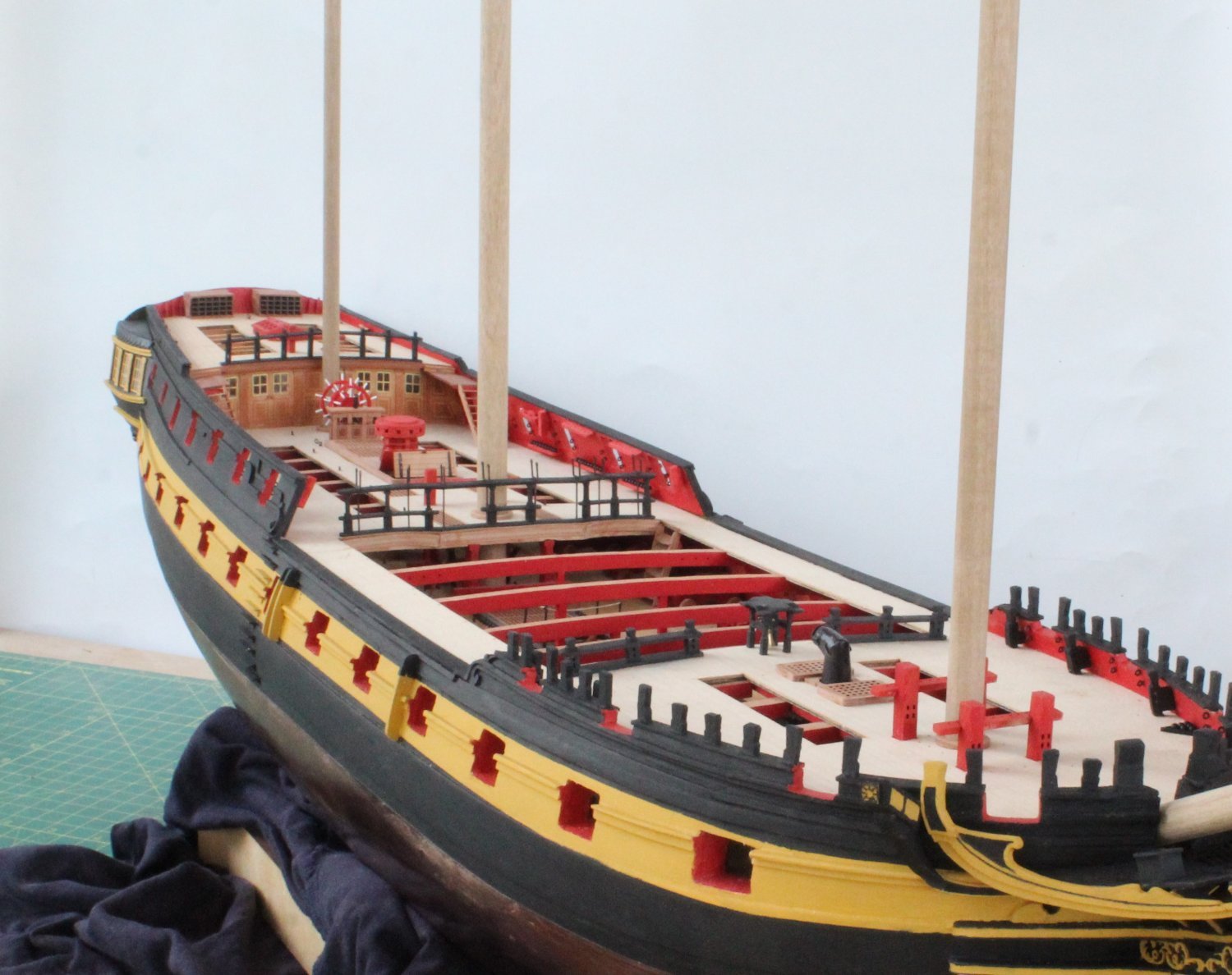
Indy Build Status Photo's
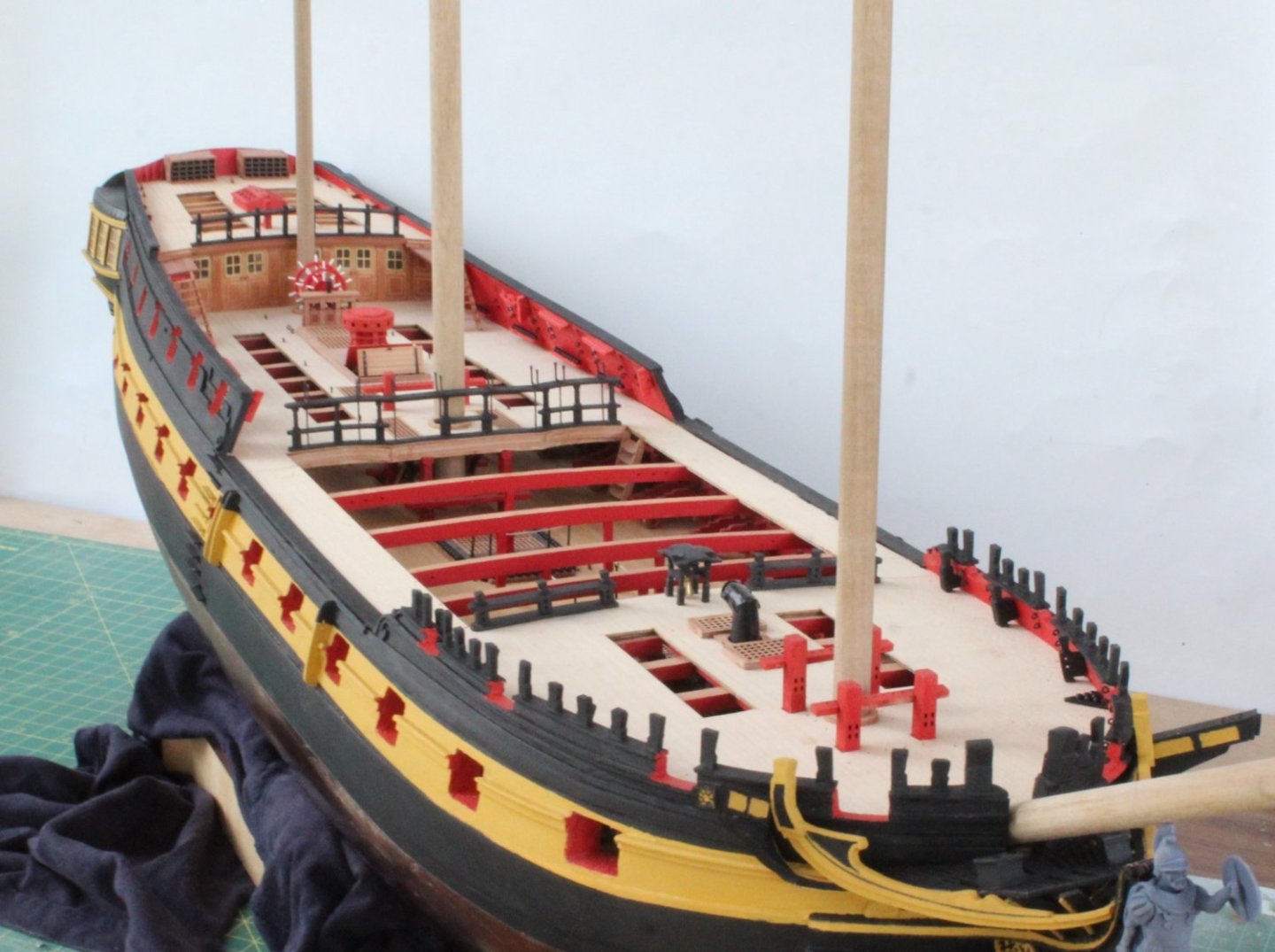

The next task will be to fit the channels and gun port lids.
-
Forecastle and Poop Deck Work
It has been a bits and pieces sort of day today. I started by adding the two belay pin racks to the forecastle bitts. I noticed the belay rack(top one) should have been installed the other way around. Thankfully it was an easy job to correct.
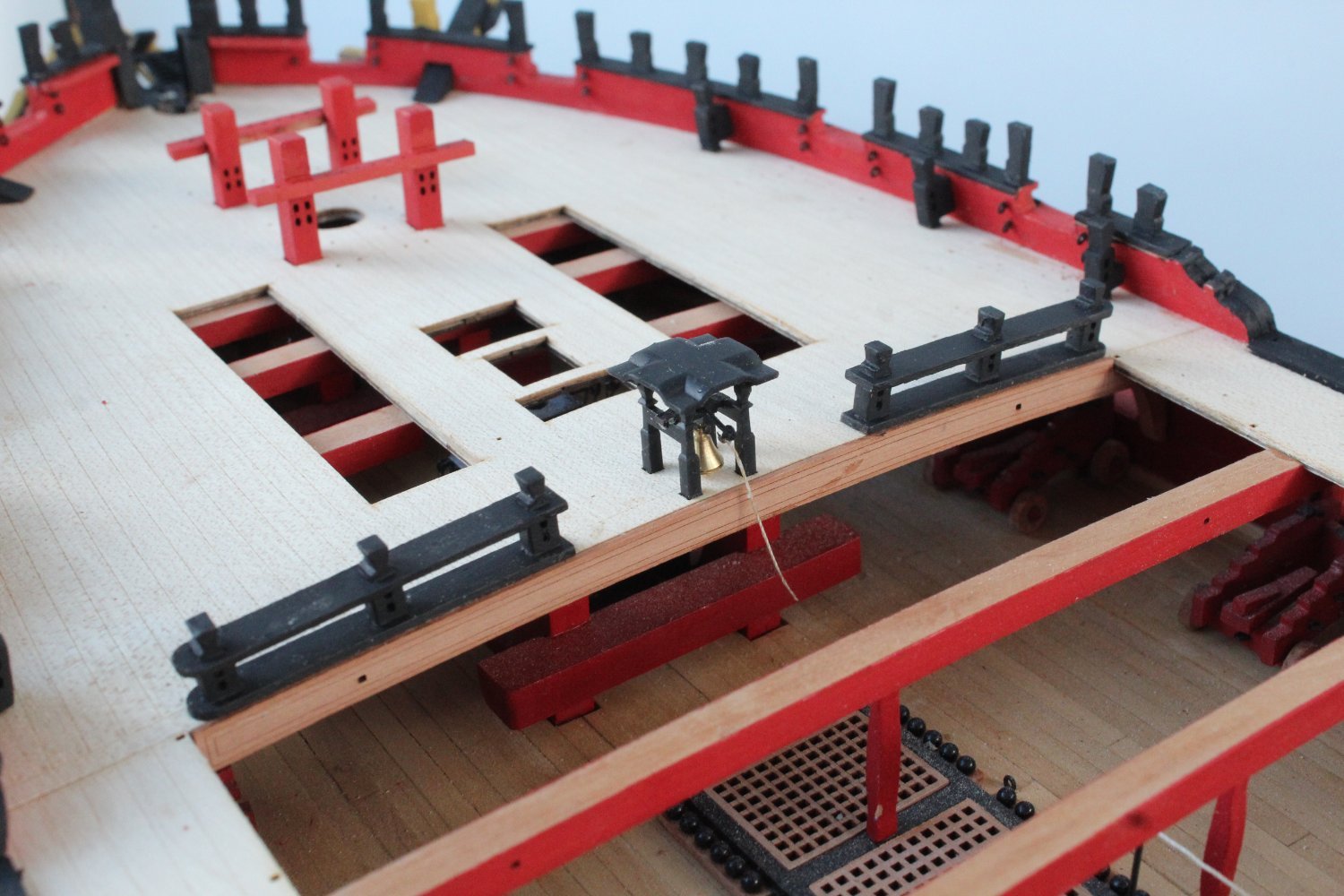
Next I assembled and fitted the belfry to the forecastle

I then turned my attention to the poop deck and added the cleats, flag lockers, skylight and bitts. I normally add the deck eyebolts during the rigging phase as sometimes I find it beneficial to add the rigging to some of the eyebolts off deck.
It is an optical illusion that the poop deck rails appear to be leaning forward in the attached photos.

The final task was to add the steps and small gangway decks (left and right) up to the poop deck.
I will continue to add more deck items over the next few days. I am leaving adding the various channels as one of the last tasks before I start making the masts and yards.
- davyboy, Thukydides, chris watton and 5 others
-
8
-
5 minutes ago, Thukydides said:
Great progress Glenn, it is looking good.
Thank you, I hope to start making the masts in a few weeks time.
- Thukydides and mtaylor
-
2
-
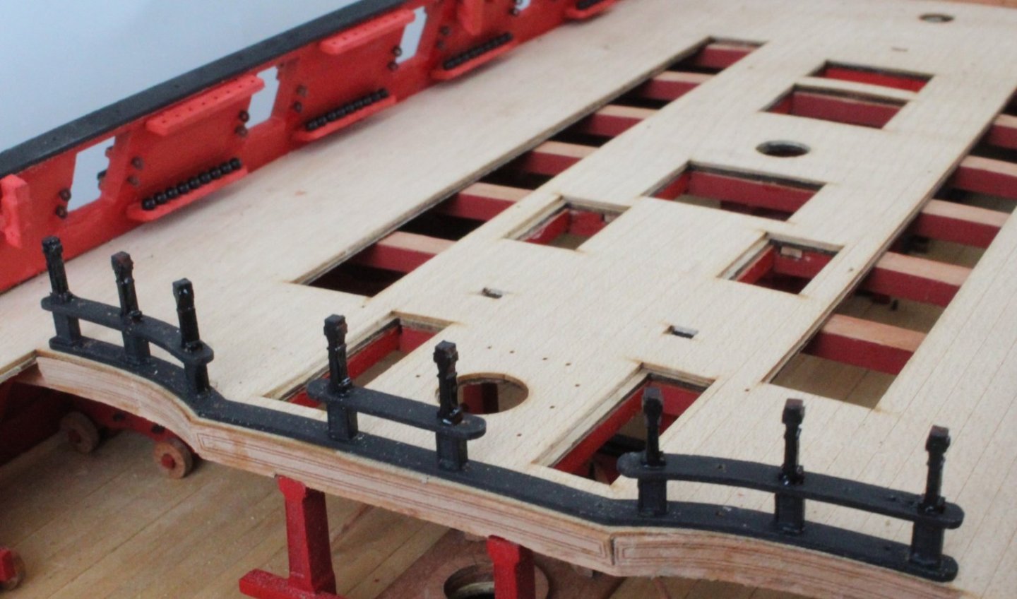
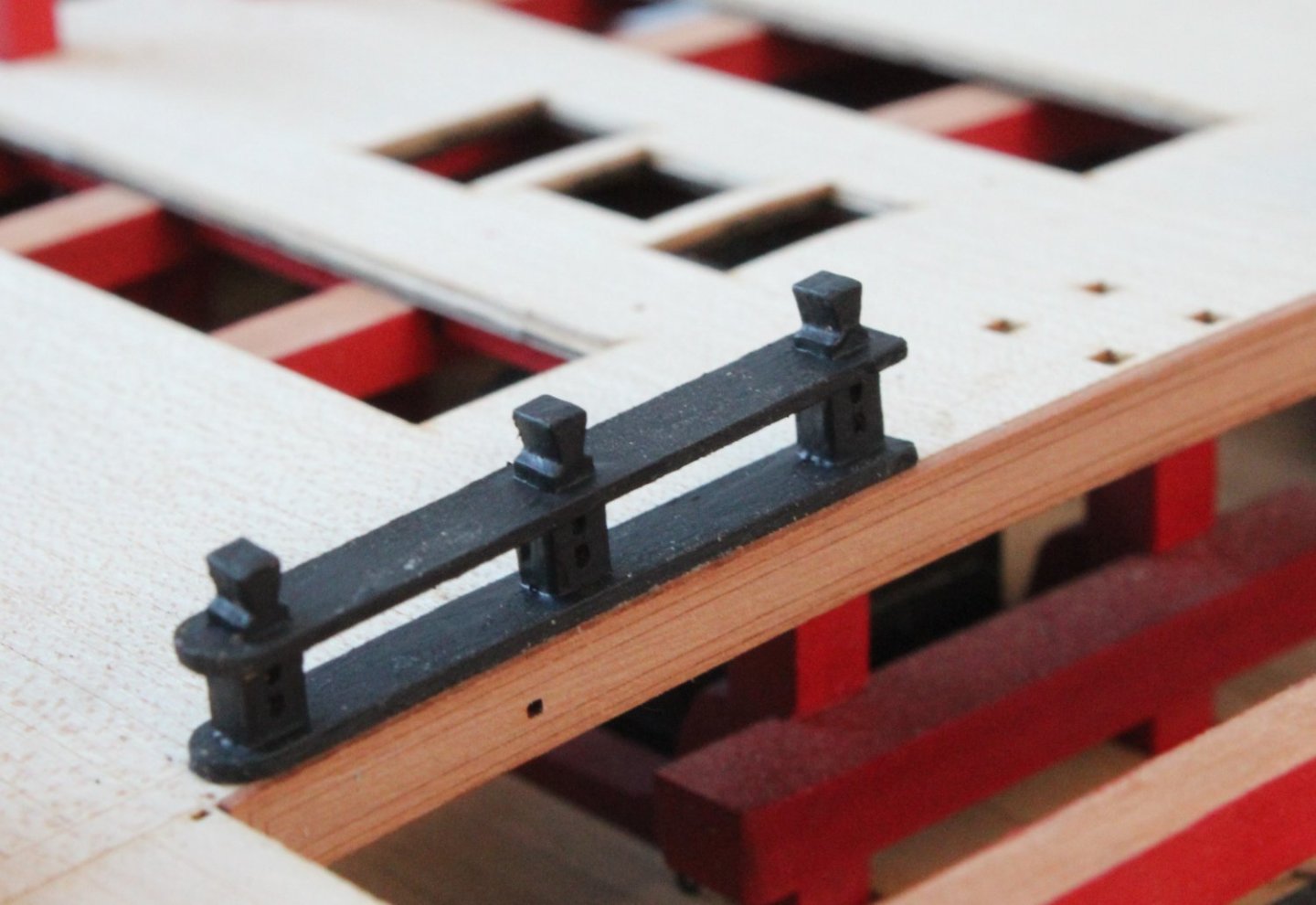
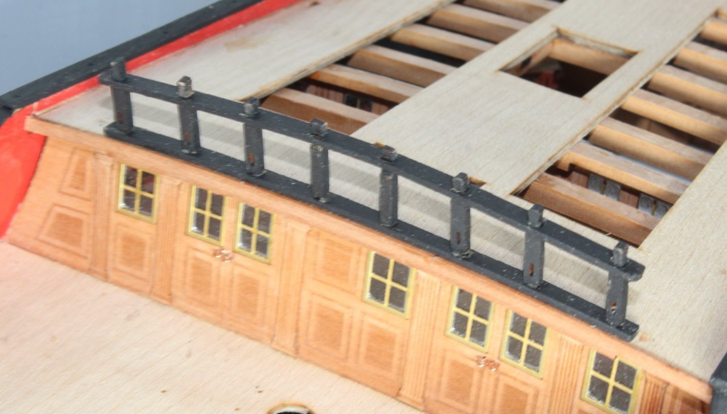
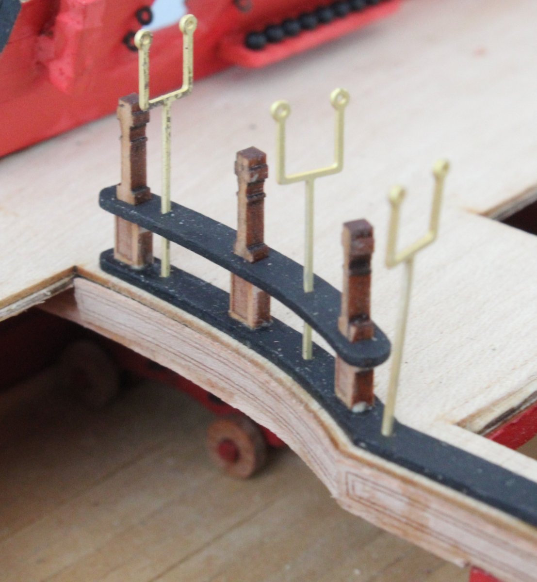
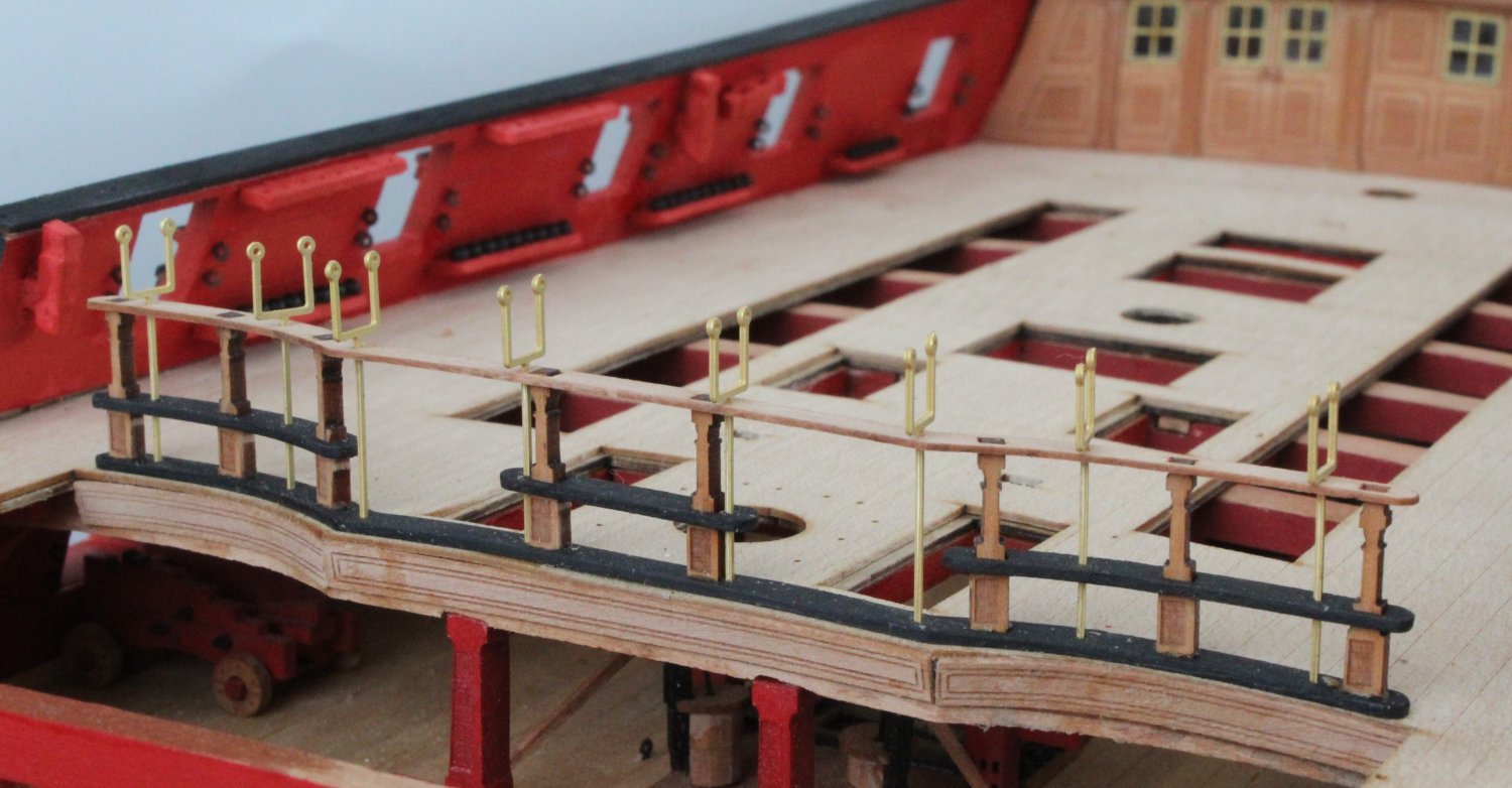
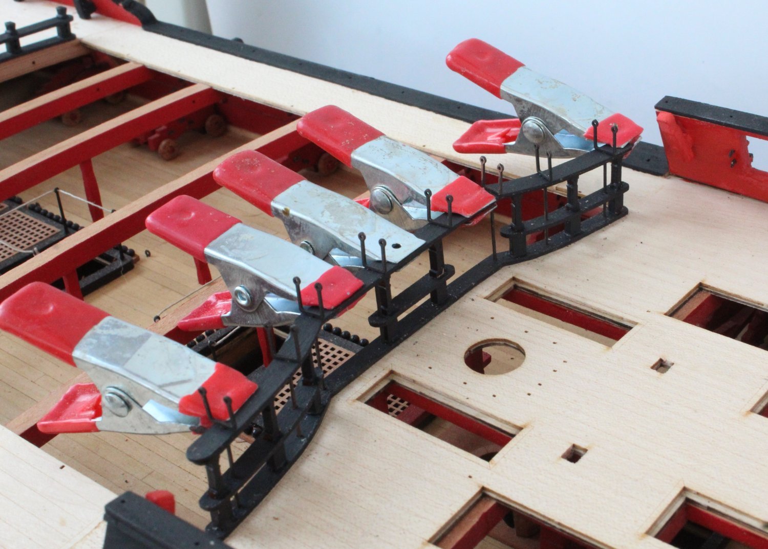
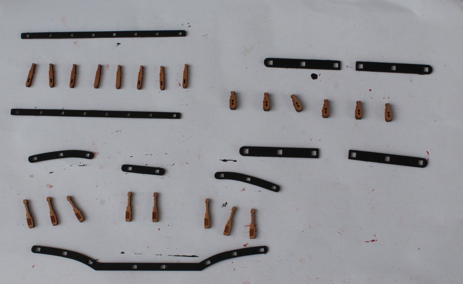
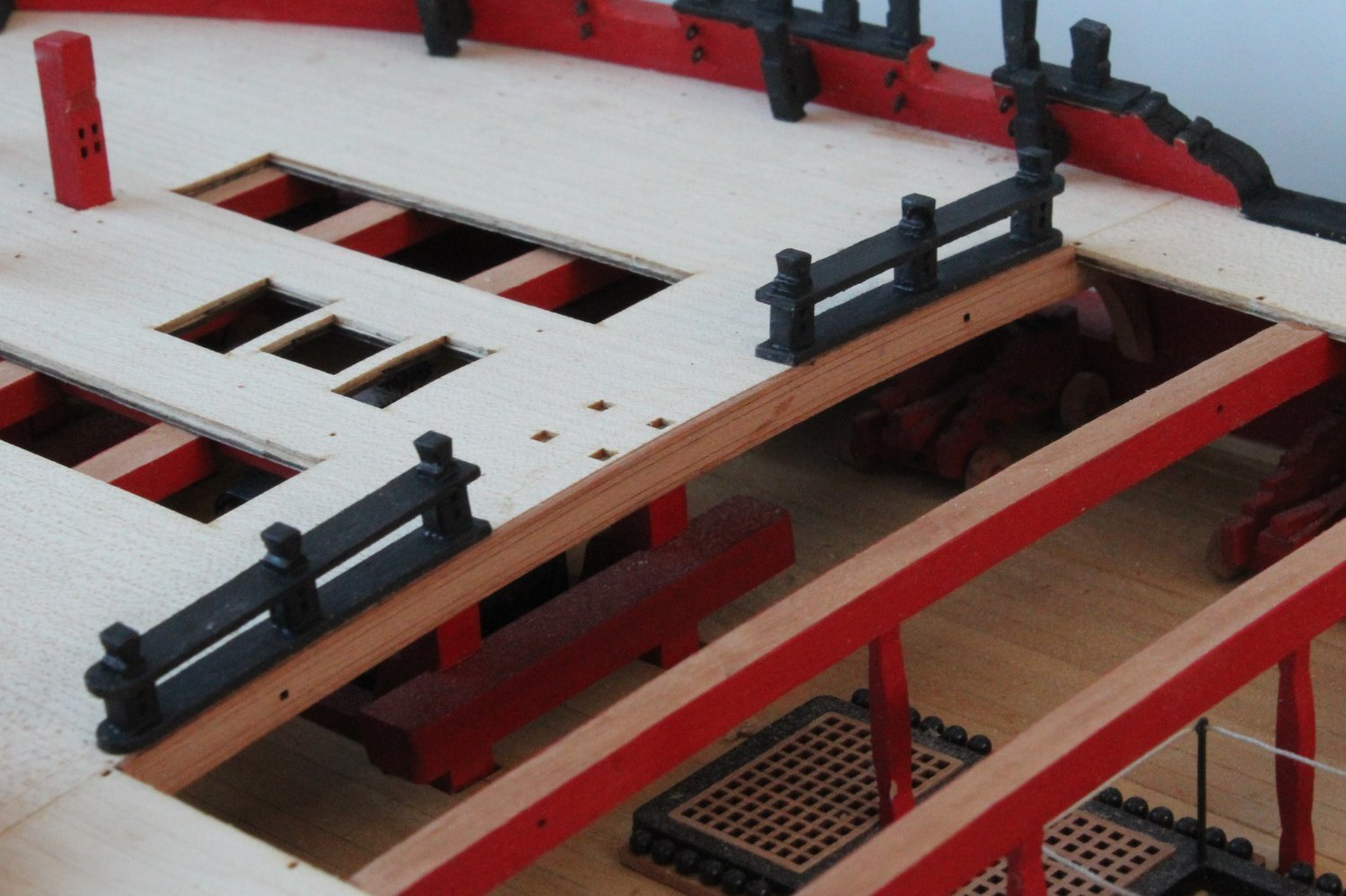
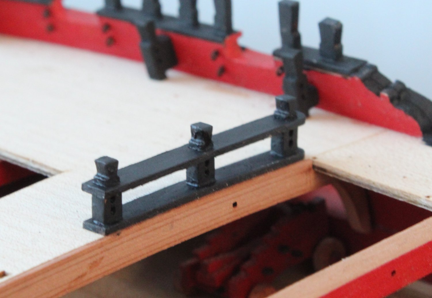
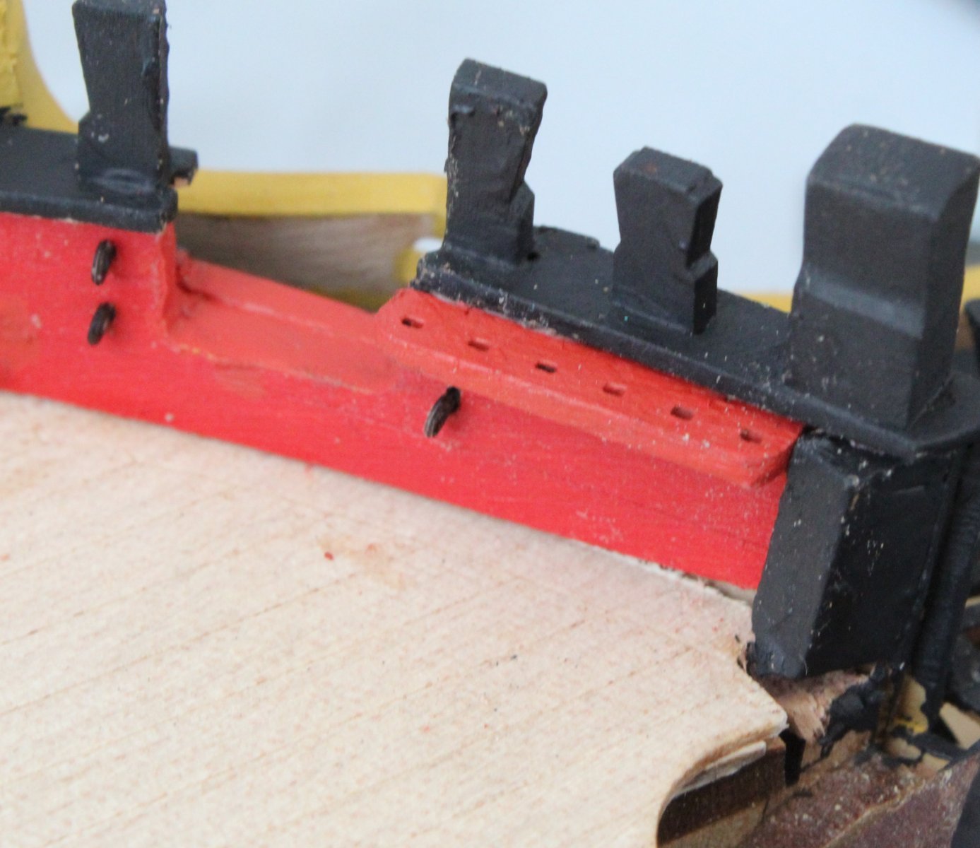
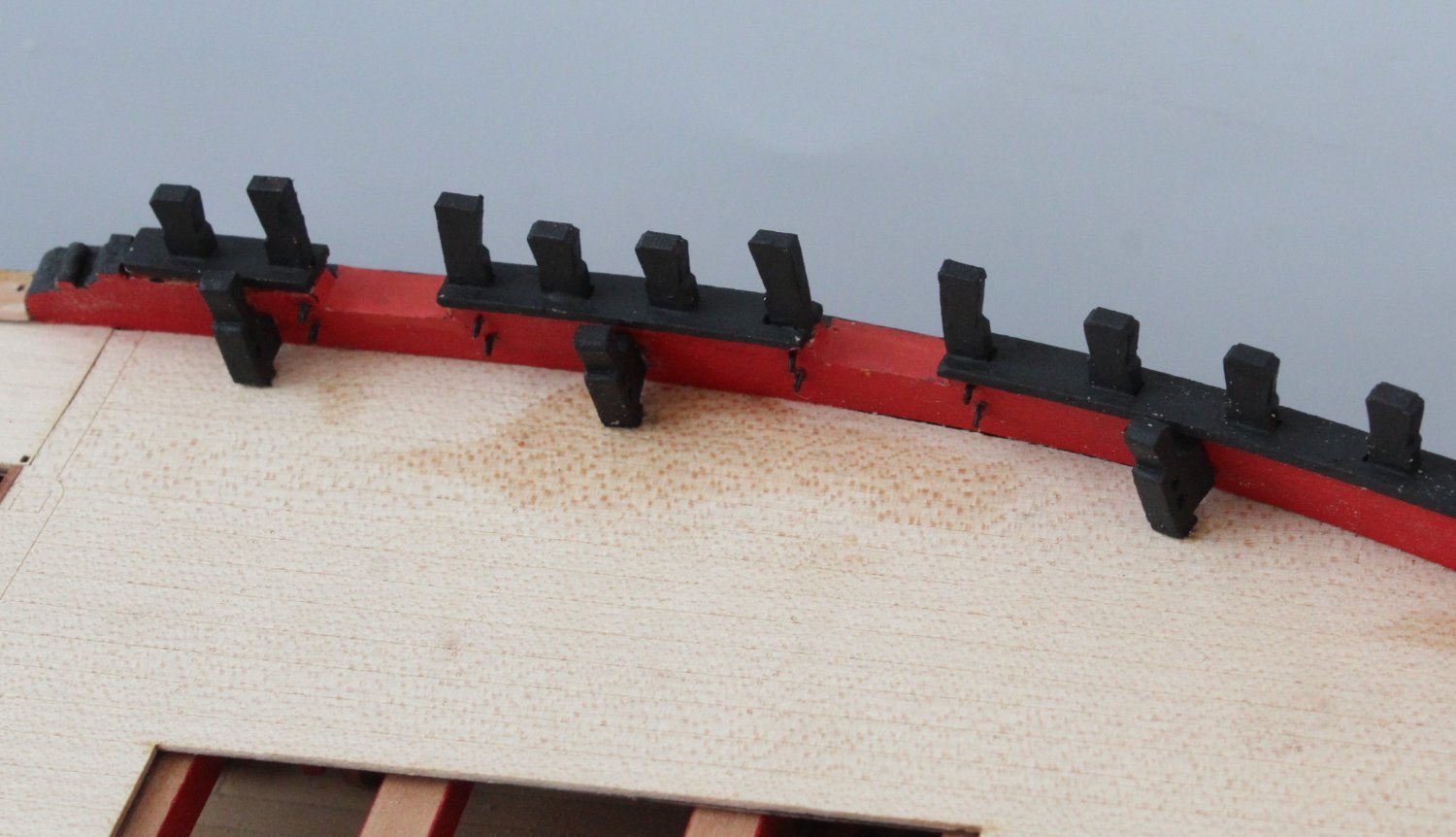
Quarterdeck Barricade Rails and Stanchions
On my return from Manchester I was able to get a couple of hours work in the shipyard and I managed to completed adding the Quarterdeck Barricade Rails and Stanchions.
I started the assembly process with gluing the Quarterdeck Barricade Stanchions in place on the lower rail. I used the hammock cranes and quarterdeck barricade mid rails as guides to ensure the stanchions were in the right position.

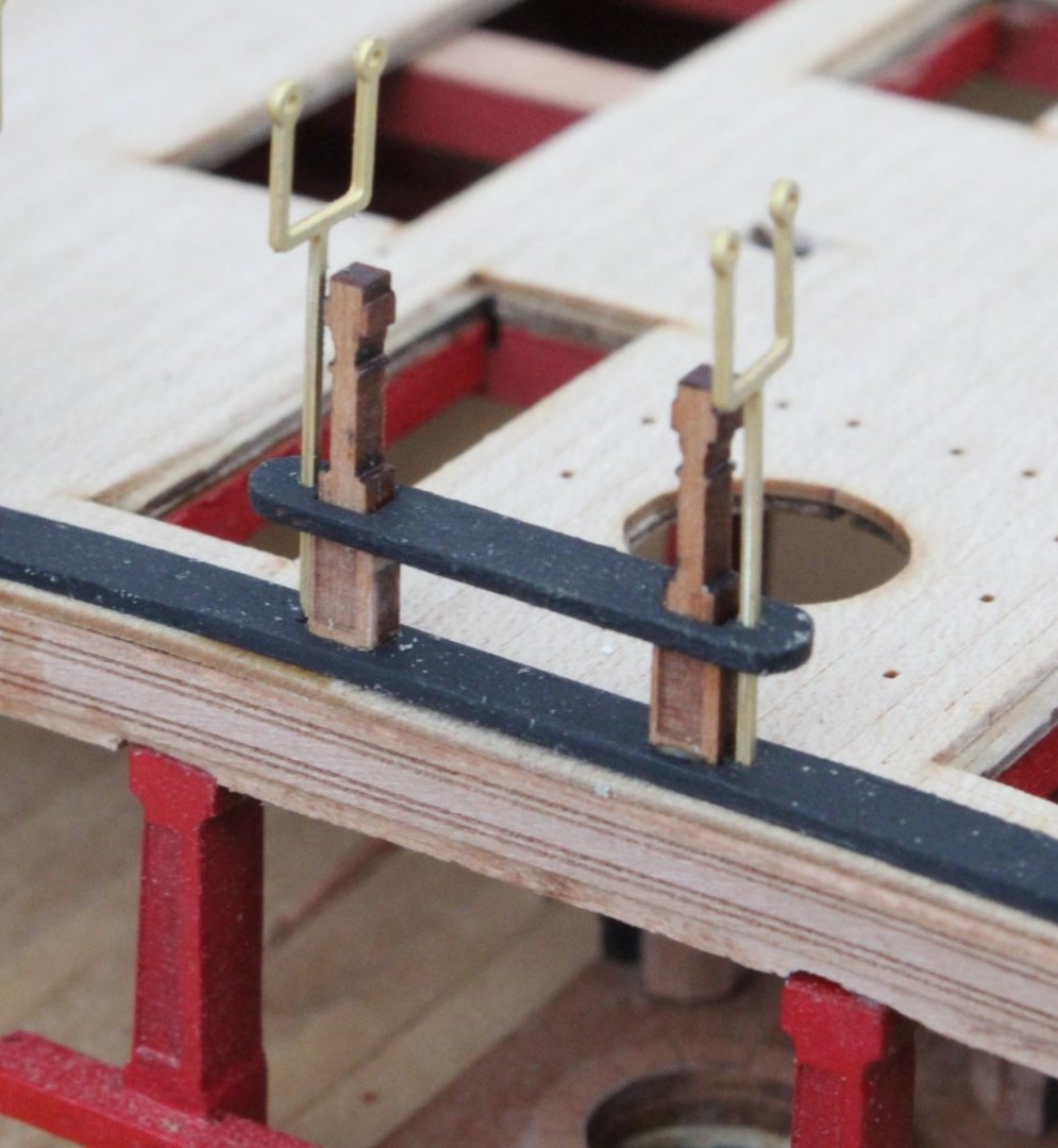
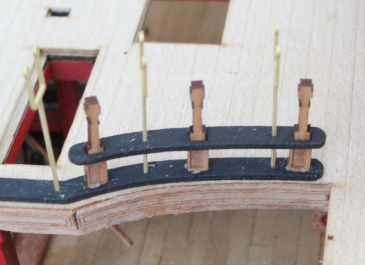
Next I checked the fit of the upper rail (lower). Everything was looking good.

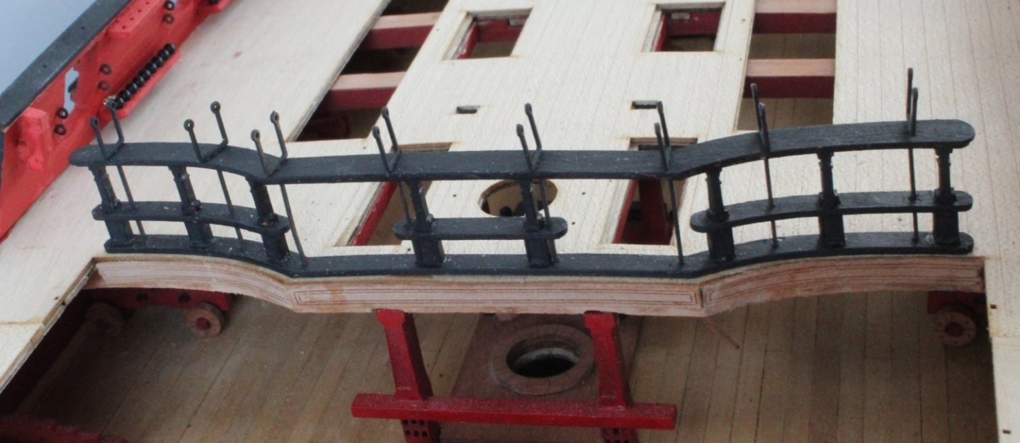
It was then time to paint the Quarterdeck Barricade Stanchions black and to then glue the mid rails in place.
The upper (lower) rail was then added, noting the hammock cranes have now been chemically blackened.
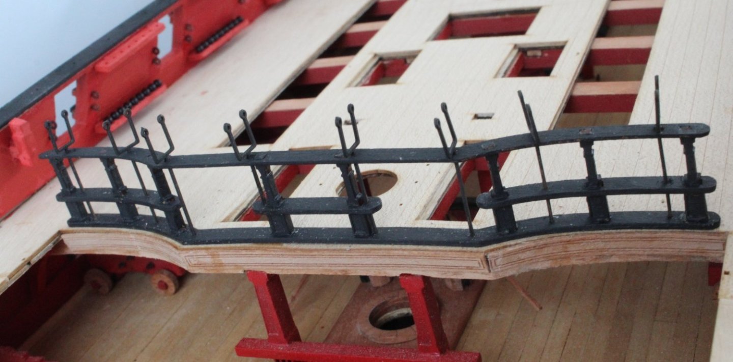
The final task was to add the upper rail, which was clamped.

The completed assembly looks good. The hammock cranes are only dry fitted for the time being, there were only used to ensure all the rails were correctly aligned during the assembly.
- scrubbyj427, JeffT, mtaylor and 4 others
-
7
-
Deck Decorations
I made the 5 remaining ladders, 2 for access to poop deck, 2 for access to gangways and one for the quarterdeck hatch.
I did a quick check of one of the walkway ladders, seems to be a good fit.
The various deck decoration parts were gathered.
The first task was to paint the parts black.
Next the base parts were glued to the decks
The forecastle deck parts were completed.


Next I did the poop deck, due to low light I used a flash light for the next photo, not a very good quality photo.
I'm off to Manchester for the weekend (to visit new grandson) so no time will be spent in the shipyard to add the quarterdeck decorations.
- scrubbyj427, DonSangria, CiscoH and 8 others
-
11
-
Quarterdeck Inner Bulwarks
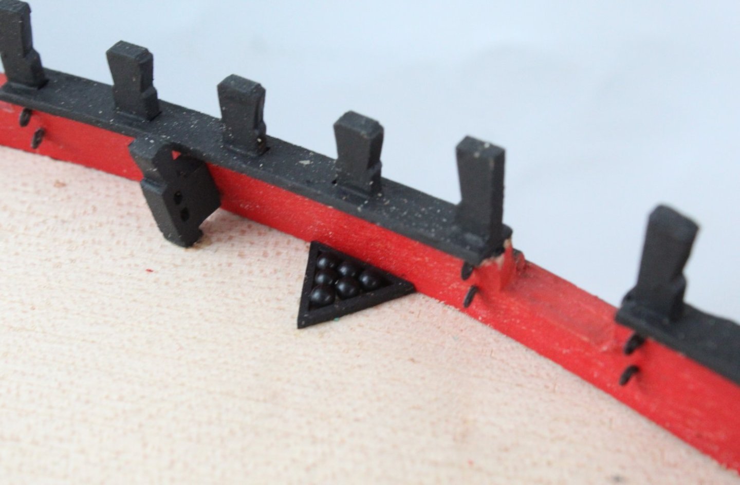
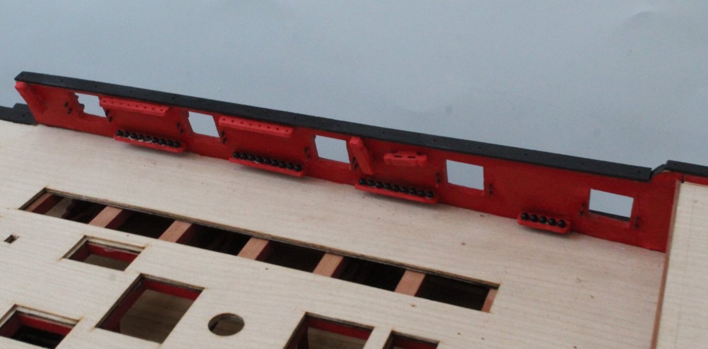
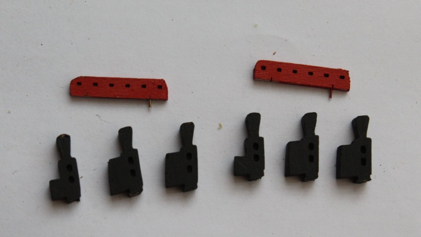
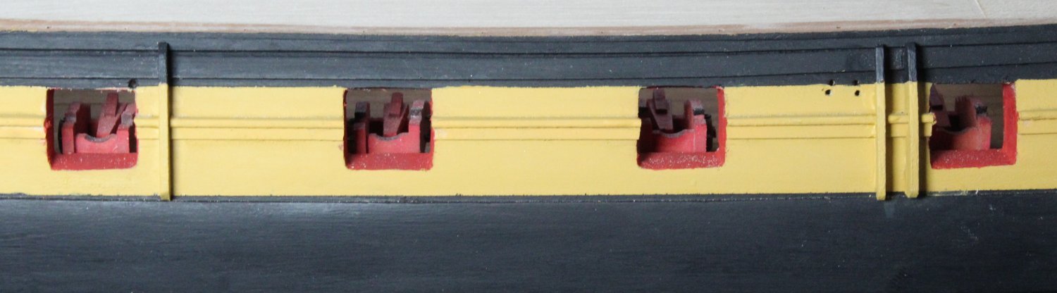
There are a few items to be added to the quarterdeck inner bulwarks, such as the cannon eyebolts and shot / belaying pin racks.
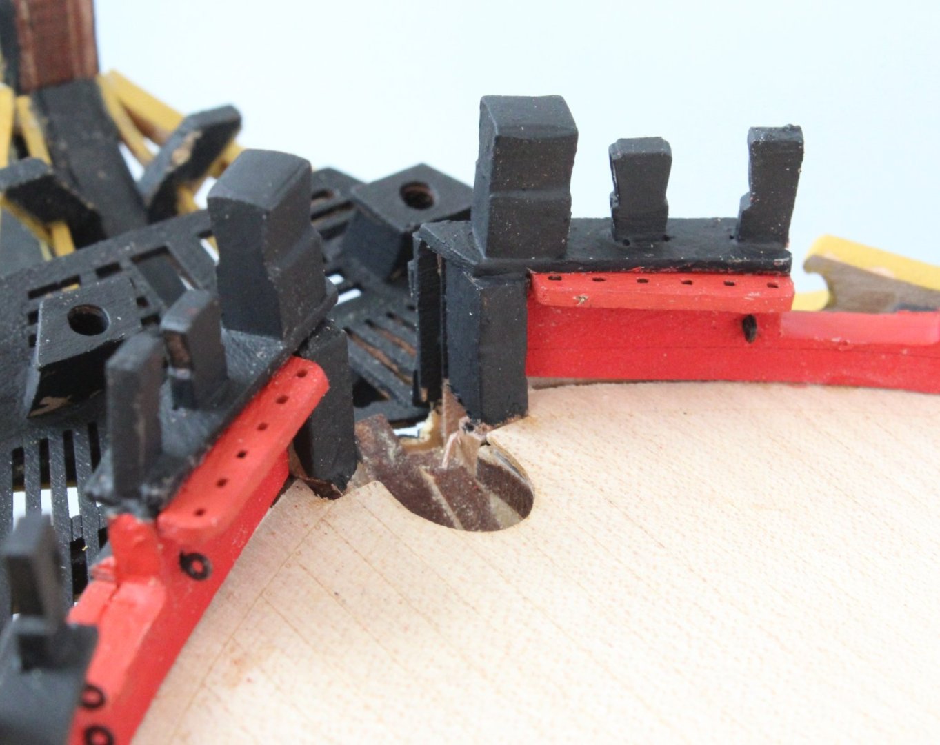
The eyebolts were chemically blackened and fitted first. With these in place the remaining items were test fitted. Pins were added to the shot / belaying pin racks, using the guidelines provided. The various items were then test fitted.

The various parts were then painted red.

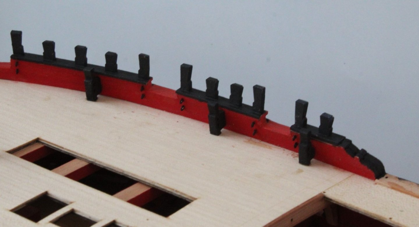
I also painted the gunwales black before the various painted parts were added to the inner bulwarks.

The final task was to add the cannon balls to the shot racks.
- ccoyle, mtaylor, scrubbyj427 and 6 others
-
9
-
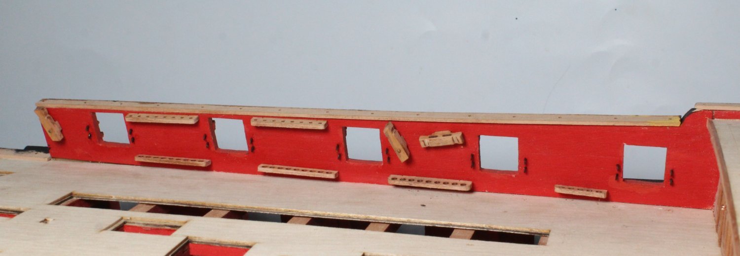
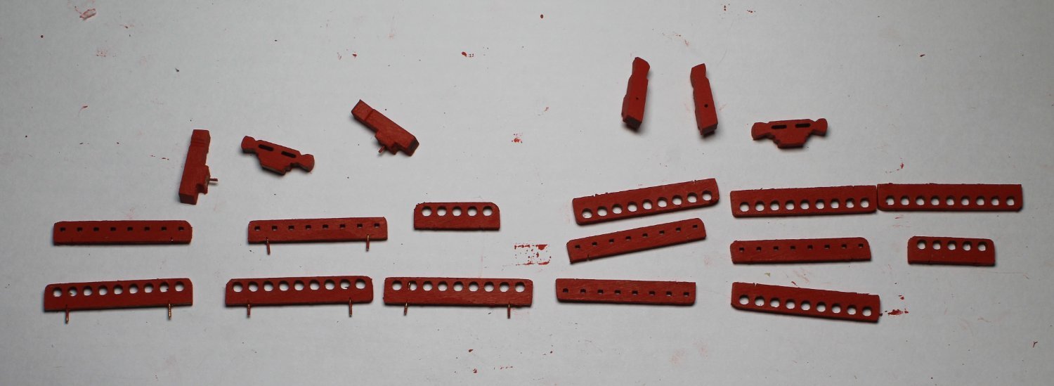
Forecastle Inner Bulwarks
The eyebolts have been added to the forecastle gunports. When looking at the build manual and plan sheets there are some additional items to be added to the bulwarks, such as belay pin racks and cavels.
The various parts were located and painted ready prior to installation. The cavels bottom edge did a slight adjustment so it was fitting flat to the deck.
Belay pin racks
I do need to clean this area from all the accumulated dust.

Cavels

- Thukydides, davyboy, ECK and 11 others
-
14
-
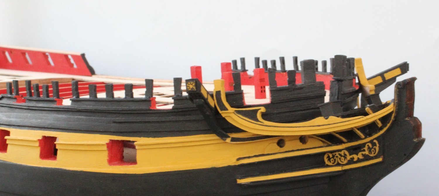
Bow Work Completed
Returned to the workshop this morning after a couple of days aways looking after our 3 year old granddaughter as her parents become proud parents to a baby boy (our 5th grandkid).
I have managed to complete adding the various rails, ekeing, knees, ledges, seats of comfort and timberheads around the bow area.

The cathead knee

As the next photo shows there is some touching up required.
I remembered to add the polybak decorative pattern, as can be seen in the next photo, to the stem post.
Seats of comfort

- Ronald-V, chris watton, AJohnson and 13 others
-
16
-
Bow Work Continues
Today has been a day of painting the various bow patterns. The various patterns were first coated with a thin layer of varnish before the painting commenced. It was then a case of adding the various colours to the different patterns.
Rails
I did use a black edging pen for the thin line black infill.
Ekeing
I decided to paint the infill area black.

Gammoning Knee rails and decorative patterns
The edging pen was used for the black infill's.

Please note that I did managed to make a repair to the inner bow ledge which has split into 3 separate pieces. The two remaining parts can be sorted when the inner bow ledge is ready to be installed on to the gammoning knee.

-
Start Of Bow Work
I think this will take a few days to complete as these are quite a few bits to paint and fit. As you will see later on in this post I have suffered a bit of a set back.
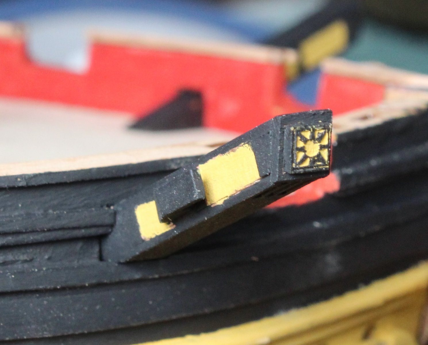
Catheads
Once these had been painted they were glued in place. As can be seen in the attached two photos I made a better job of painting the left-hand side decorative front pattern.
I will be able to touch up the one below a little bit.
Gammoning Knee / Bow V Frame / Bow Rails
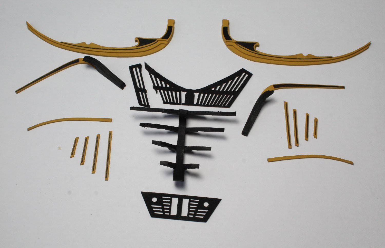
As per the build manual instructions I added the decorative patterns to the Bow V frames attached to the gammoning knee.
According the build manual instructions one of the bow rail patterns is then fed through the gap between the v-fames and decorative patterns. The manual does indicate that it might be necessary to file an angle in the openings in order for the pattern to be fed through.
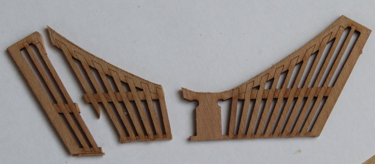
After a bit of filing I was concerned that I might break the bow rail pattern as I was struggling to feed it through the openings. I was also aware that once in place it might be necessary to trim the pattern to suit my build. Therefore I decided to remove the decorative patterns so that the bow rail pattern could be trimmed. Thankfully the patterns were easy to remove, without damage. As shown in the next photo I have been able to trim the right hand side bow rail pattern.

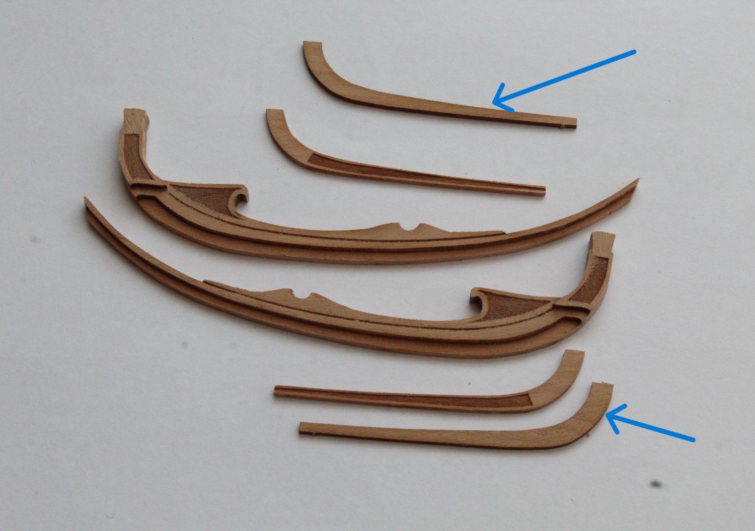
Bow Rails and Ekeing Patterns
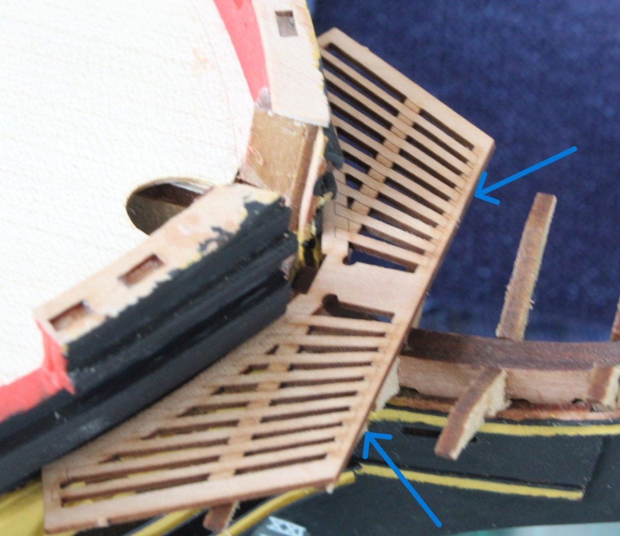
The other bow rails (left and right) are made up of three parts each, which were glued to together. The kit has an inner and outer ekeing pattern (left and right). As far as I can tell, by looking at the various prototype build log photo's, the two inner ekeing patterns (part no. 214, blue arrows in the next photo) are not required. The bow rails and ekeing patterns are ready to be painted.

Cathead Knees
This was an interesting build project. The kit is supplied with two jigs (left and right) to make the cathead knees. Each knee will comprise 5 patterns which need to be bent, using the jig, before they are glued together. The patterns were soaked in hot water for around 30 mins and then placed in their respective jig(s).
Once the parts had been left overnight to fully dry out they were released from the jig(s) and glued together. They will require a little bit of tiding up before painting and fitting.
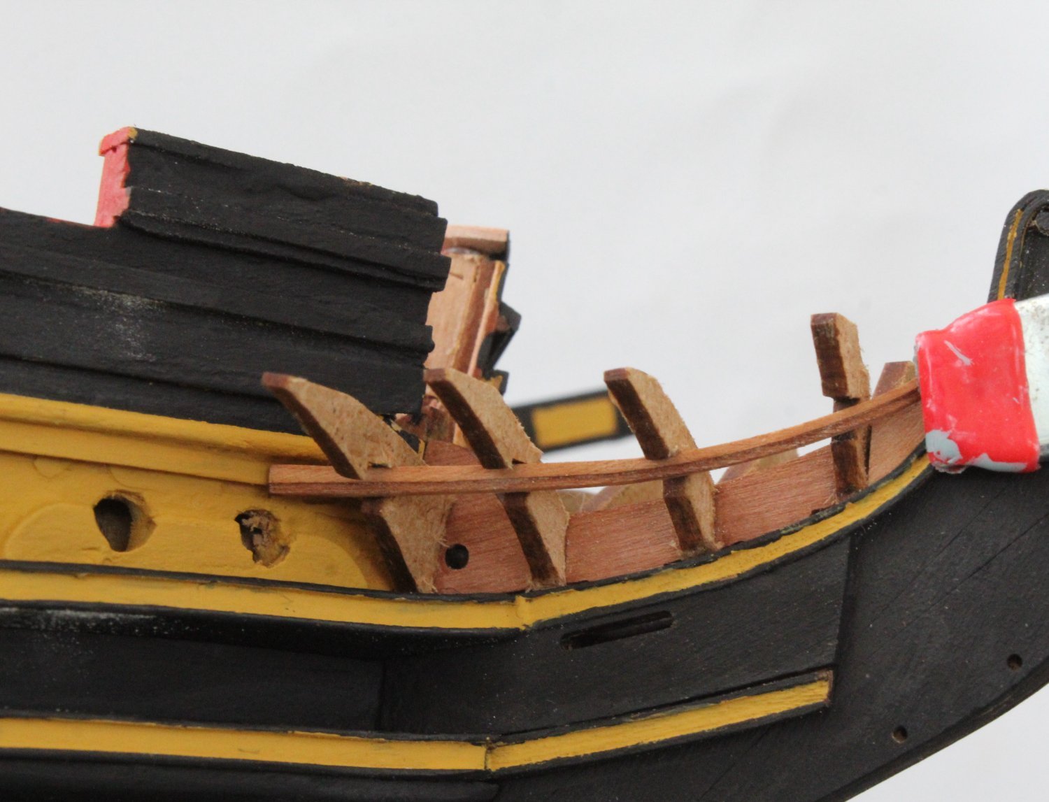
Bow Ledge Inner
With the gammon knee assembly (dry fitted) in place I did a trial fit of the Bow Ledges. Although the inner bow ledge seemed to be a reasonable fit around the bow it was not perfect as there was no room on the v frame pattern, as indicated by the two blue arrows, for the outer bow ledge pattern.
I made a replicate inner bow ledge pattern using some stiff cardboard and, after making a few minor adjustments, I was happy with the overall fit. I then transferred the markings from the template to the bow ledge pattern and started to make the required adjustments. All was going to plan. The slight adjustment to the front (bow) had been made. I now needed to make a minor adjustment to the back edge to complete the task.
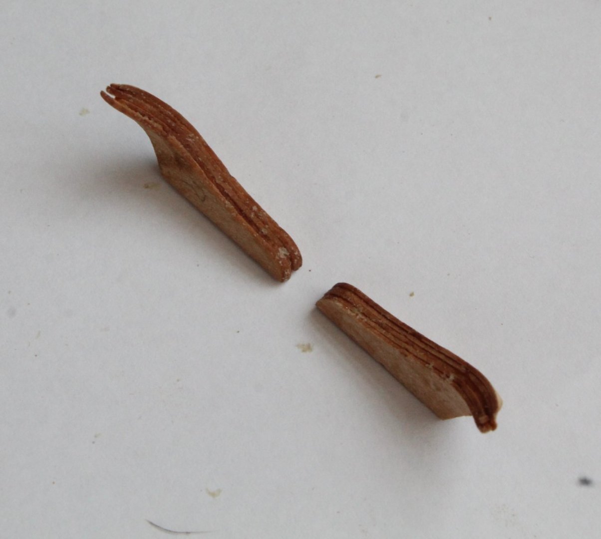
As I started to work on the rear edge of the bow ledge pattern disaster struck as the pattern suddenly split into 3 separate pieces, as shown below. I am hopeful that I can still install the bow ledge pattern.
- ECK, KARAVOKIRIS, AJohnson and 5 others
-
8
-
Amazing work, you are a truly inspiration to us less worthy modelers.
- mtaylor and Blue Ensign
-
1
-
 1
1
-
In todays build log post I have detailed the method I used to assembly the ship's steps and the channels.
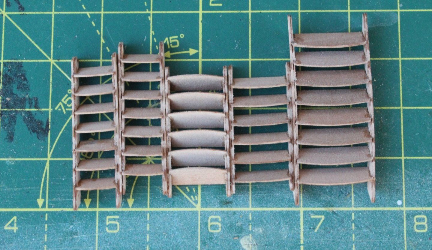
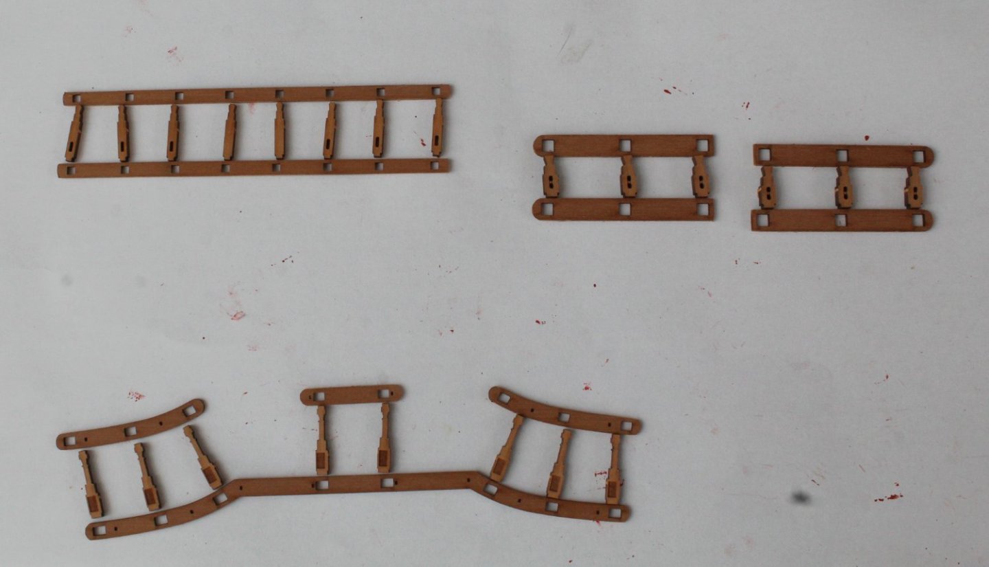
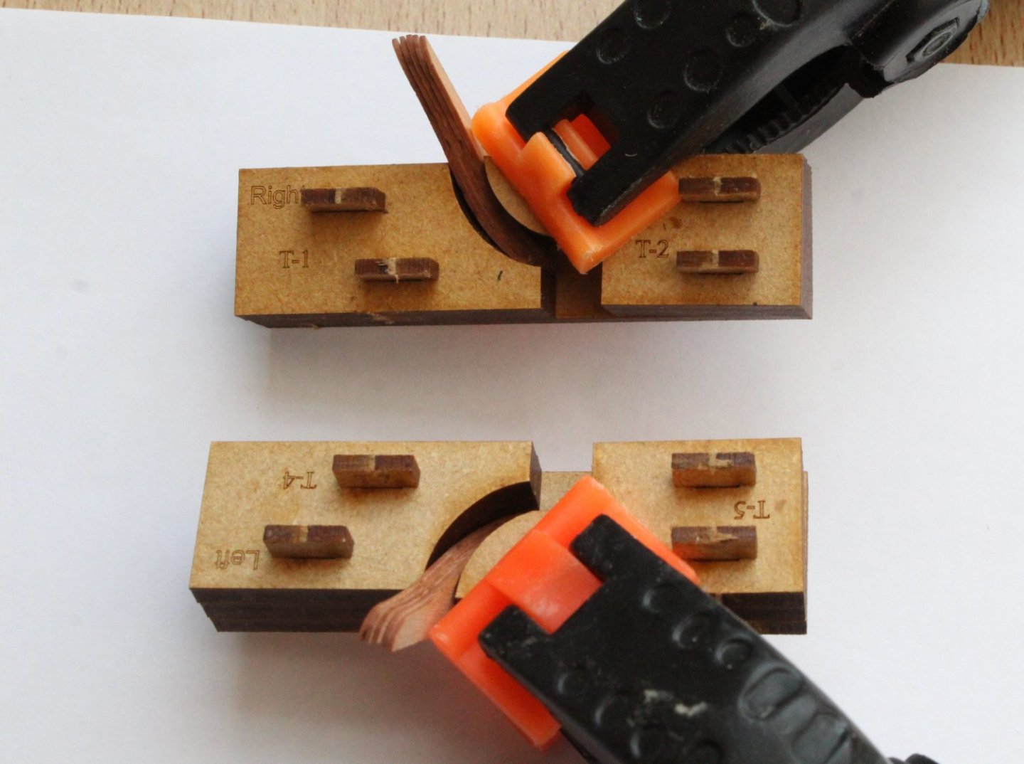
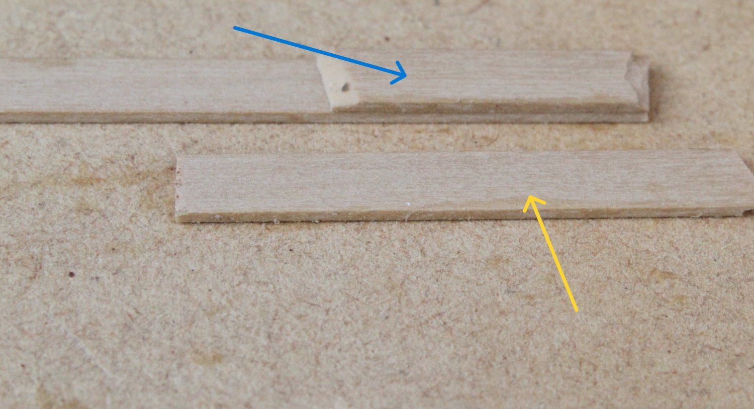
Indy's Steps Assembly
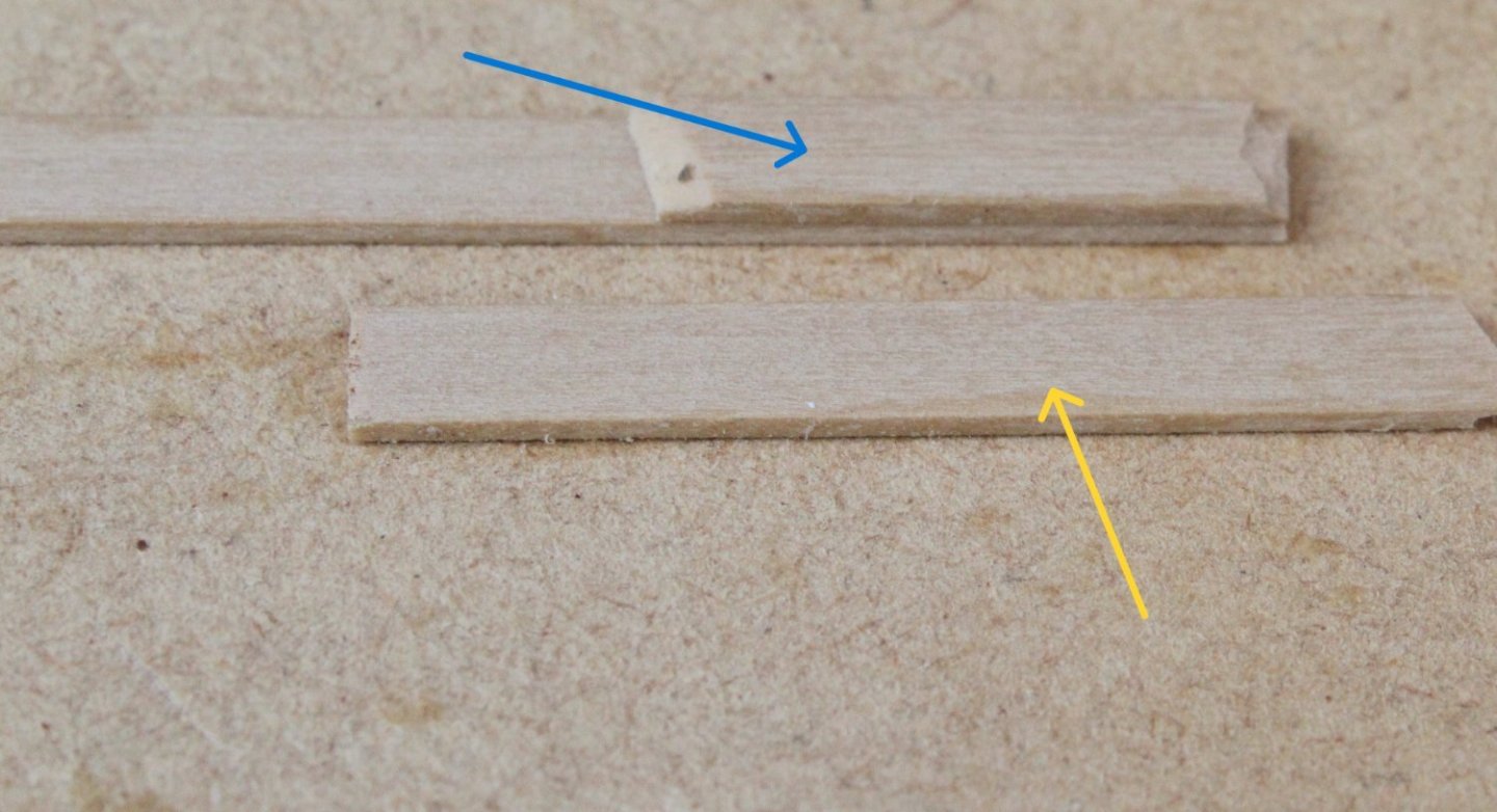
There are 10 steps required per side and each step comprises two 0.6mm pear wood pieces which have be assembled at right angles to each other. As these are quite small and fiddly pieces I decided to make a simple jig to assist me with the assembly process. I glued two small lengths of scrap planking material to a wooden base, as indicated by the blue arrow in the photo below. A second length of planking material (yellow arrow) is not glued and will be used as brace.
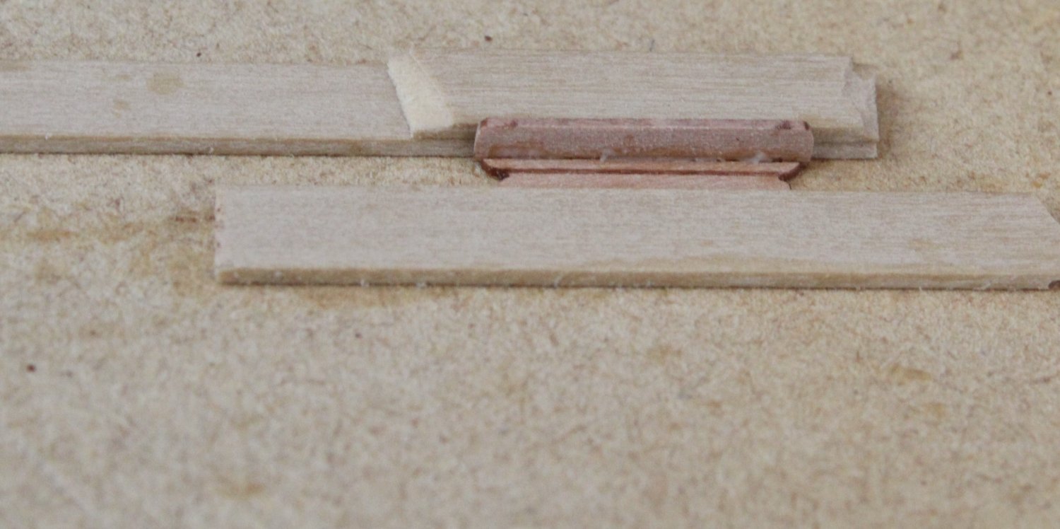
Once the laser char had been removed wood glue is added to the lower part of the back section before it is positioned in the jig, as shown below.
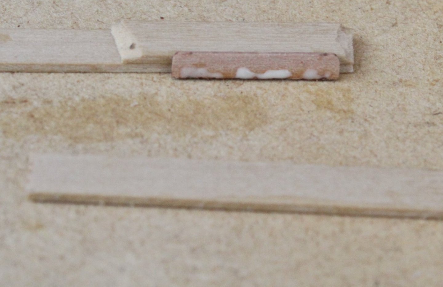
The other step part is then slowly pushed into position using the brace and is adjusted left / right as necessary. Once the parts are properly aligned pressure is applied to the brace for a few seconds. The brace can then be removed so the step can be gently eased out and left to cure.
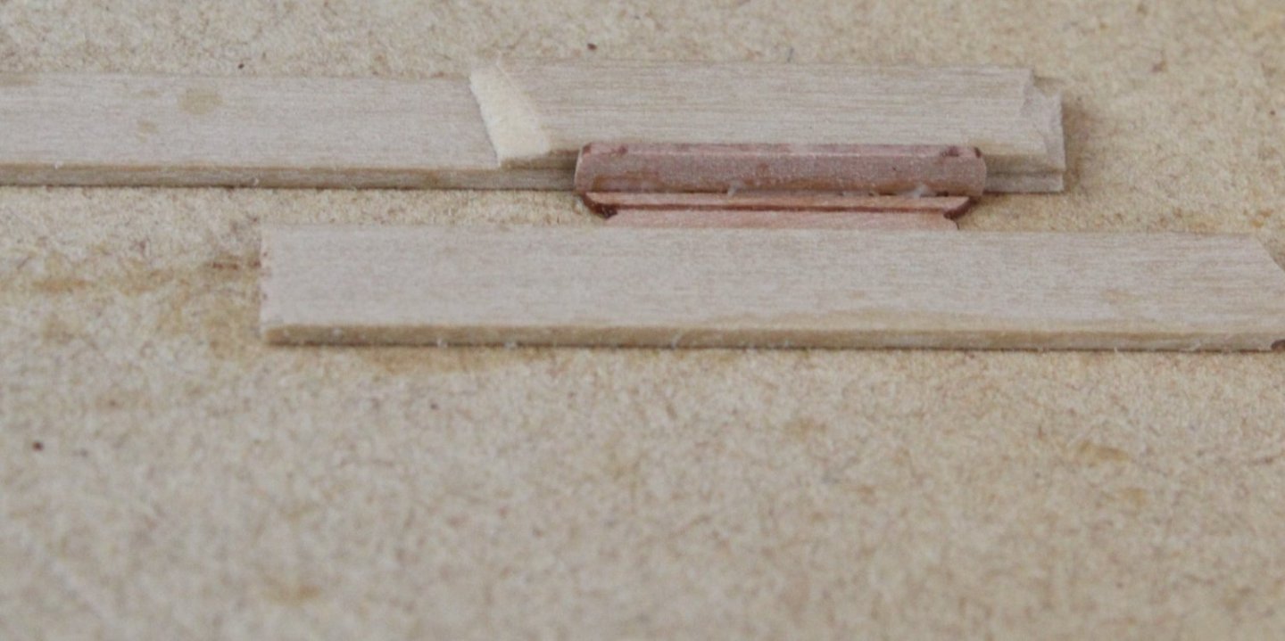
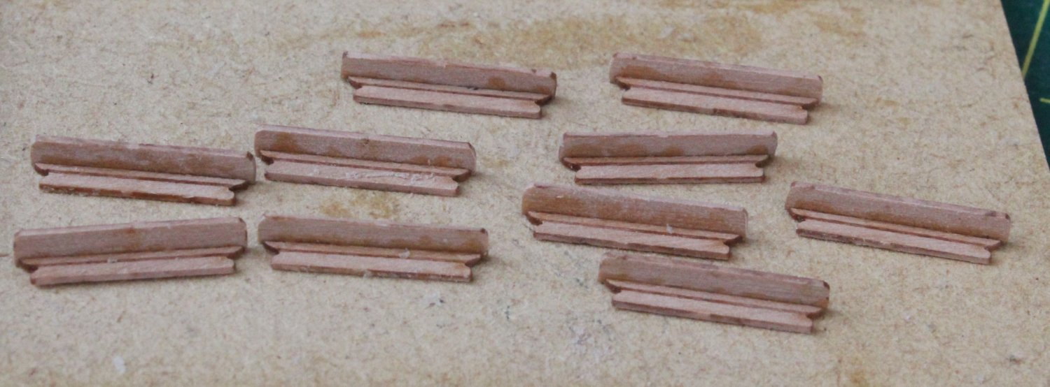
It was a fairly quick process to produce the first 10 steps.

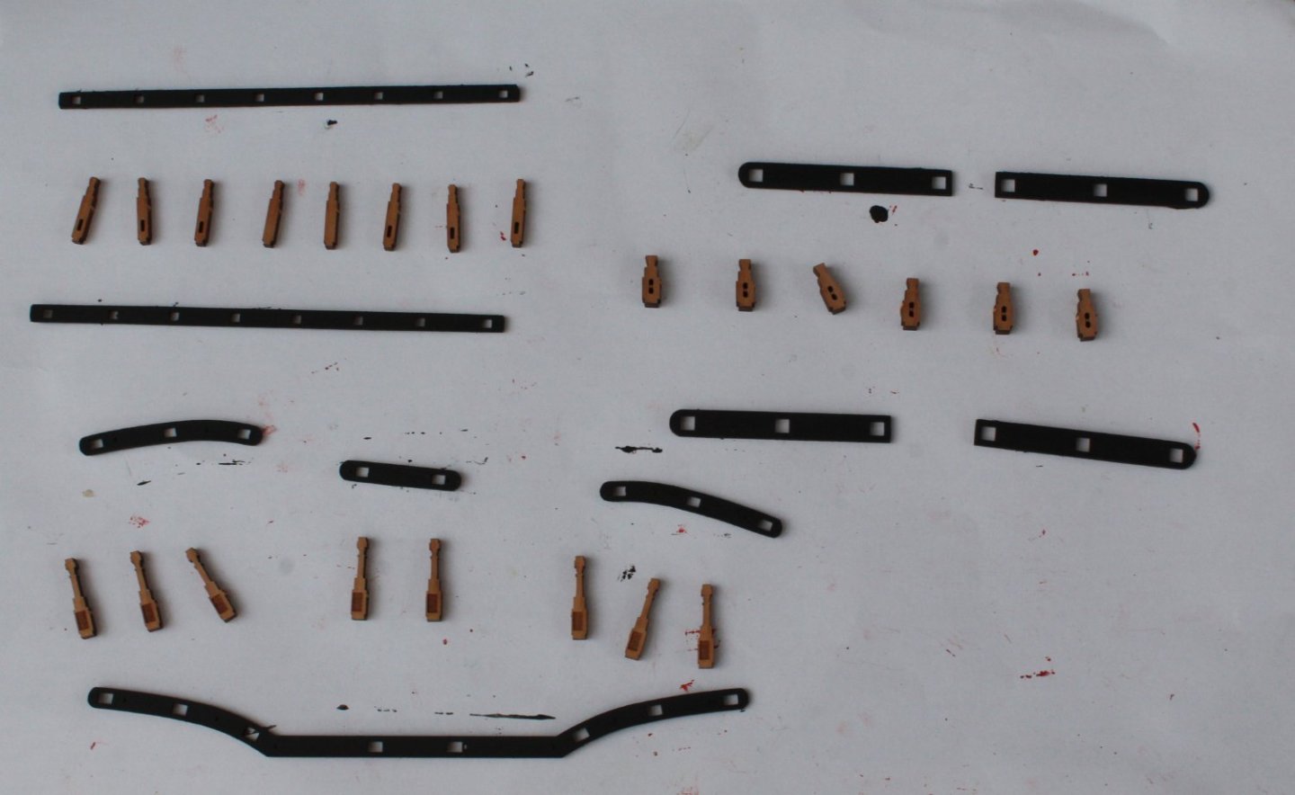
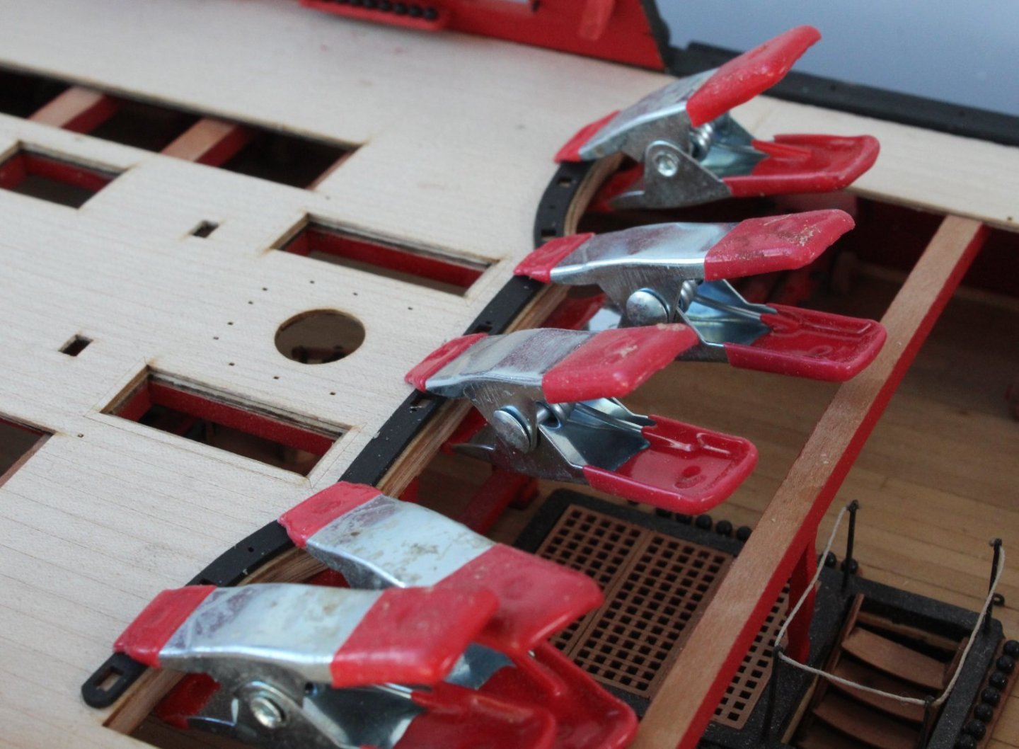
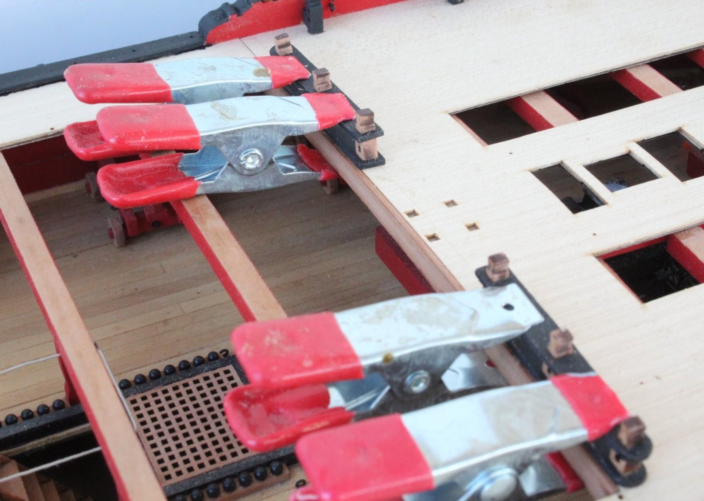
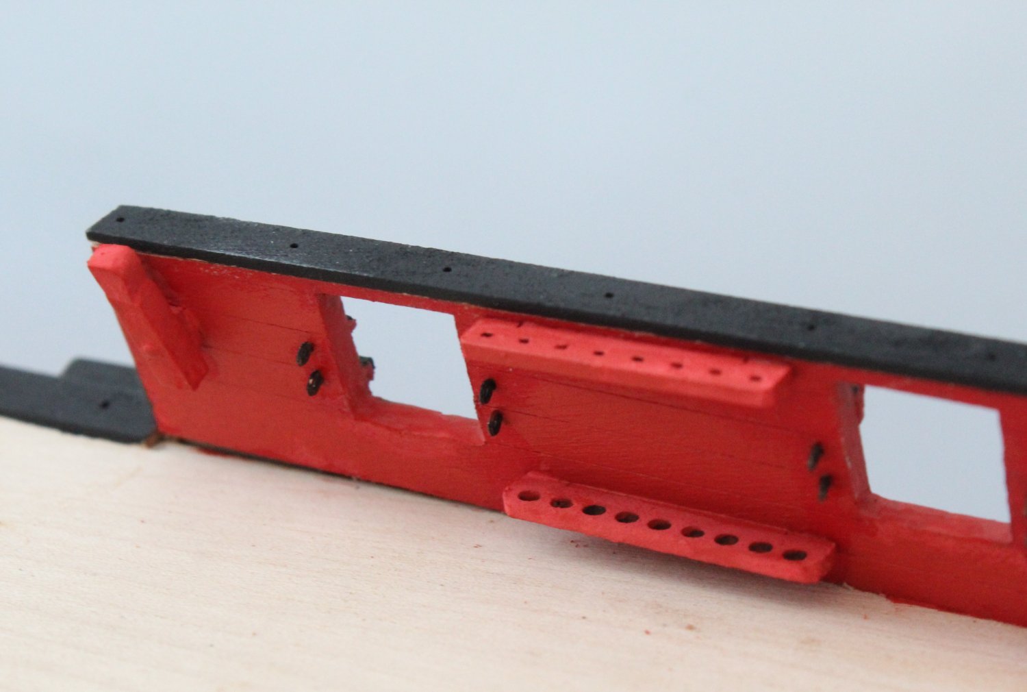
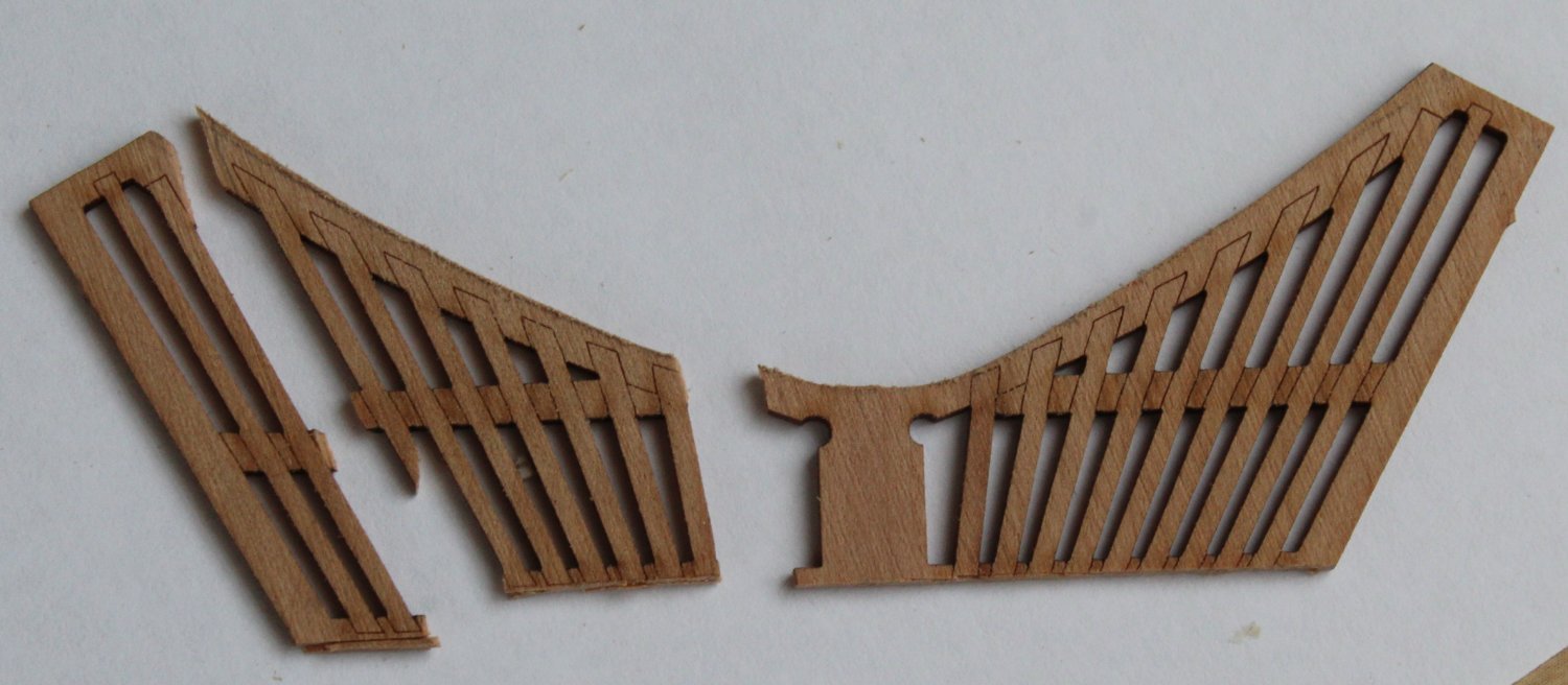
Channel Assembly
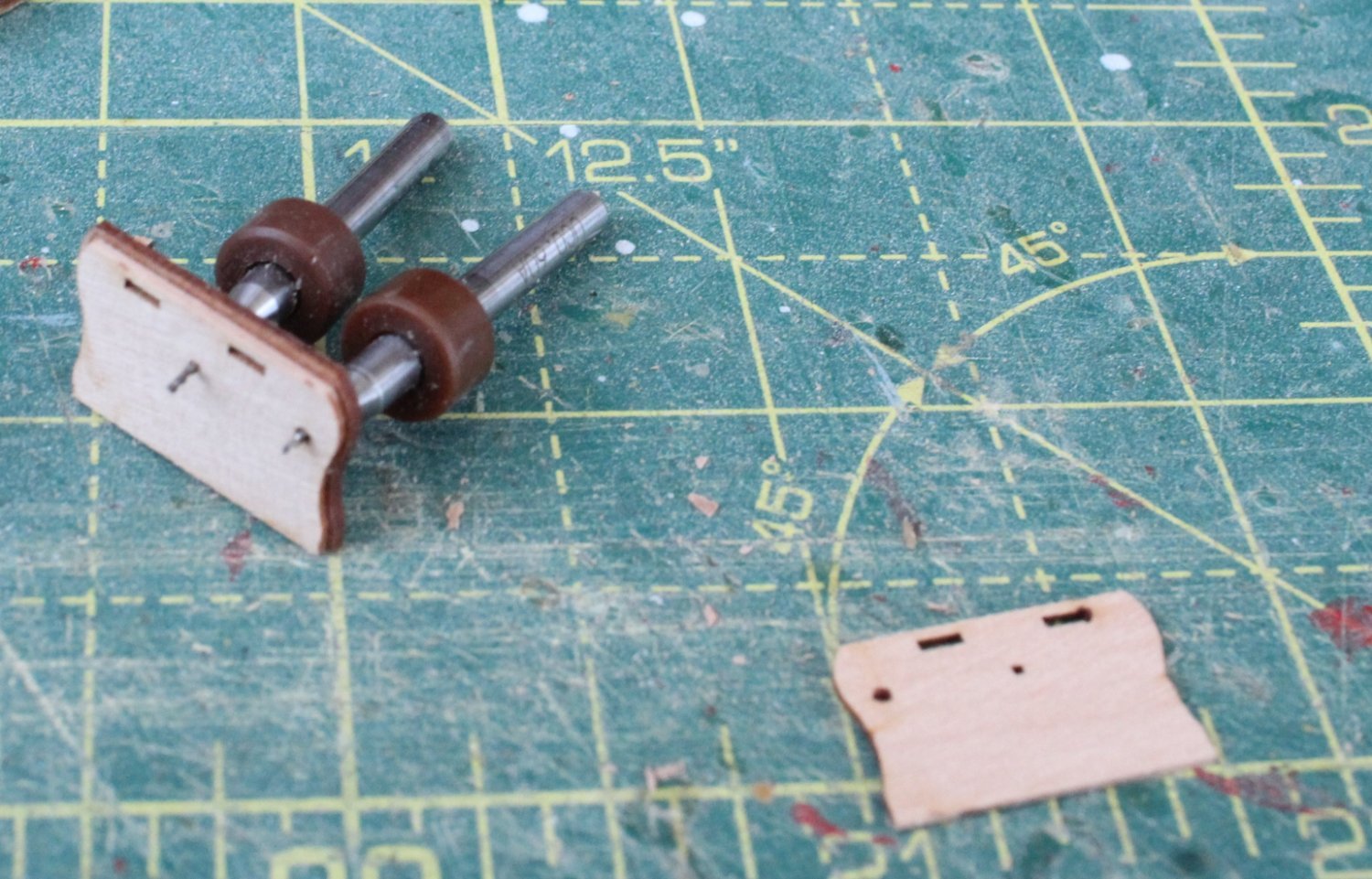
There are 5 channel assemblies required per side and each channel comprises three wooden parts, one is the central section and the other two are slightly smaller and to be glued either side of the central piece. It is essential that these parts are correctly aligned so the various iron work parts can be added, such as the strops and eyebolts.
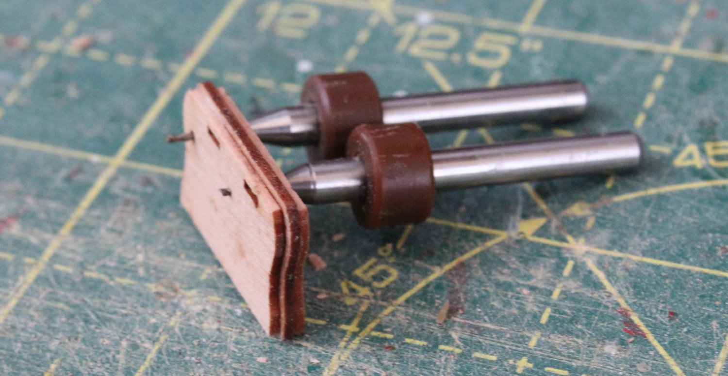
A layer of wood glue is applied to one side of the central channel section and using some old broken micro drill bits, located in the holes the first two parts are aligned.

Glue was then quickly applied to the other side of the central section and the remaining part was positioned, once again using the drill bits as a guide.

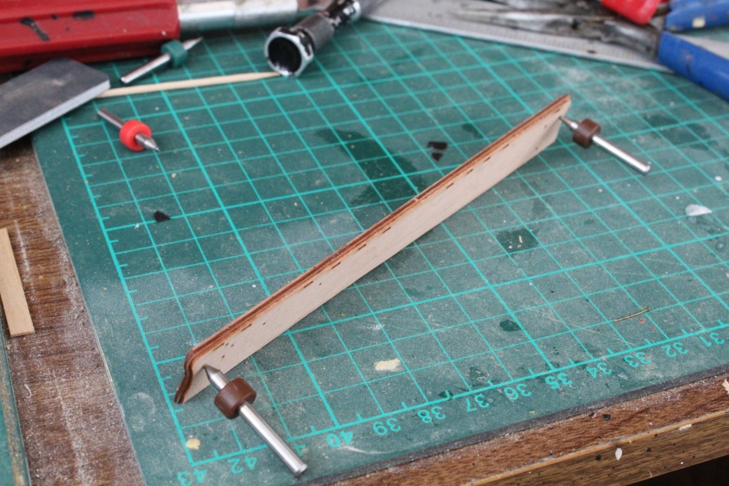
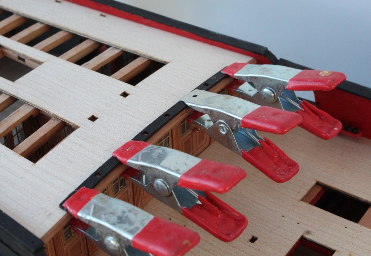
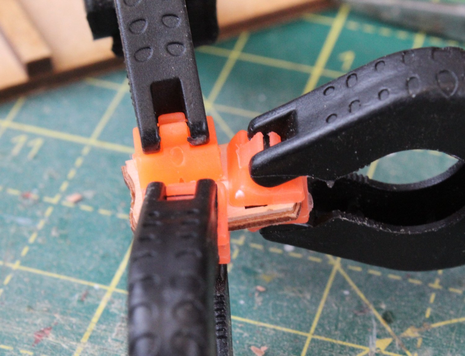
It was then a case of adding clamps to the assembly.

Once the glue had been given time to cure, the clamps were removed. The locating pins (were added (but not glued at this stage) so a test fit of the channels could be made.
- ECK, Crofty, KARAVOKIRIS and 8 others
-
11
-
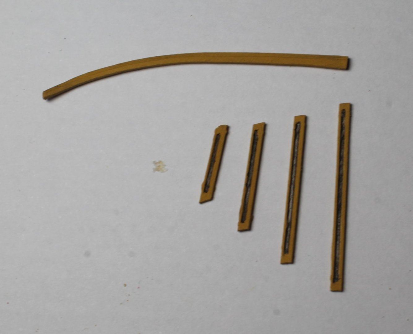
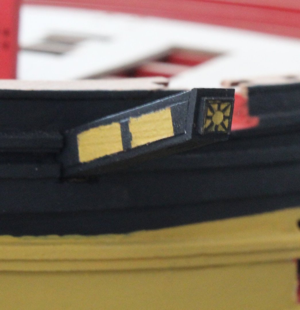
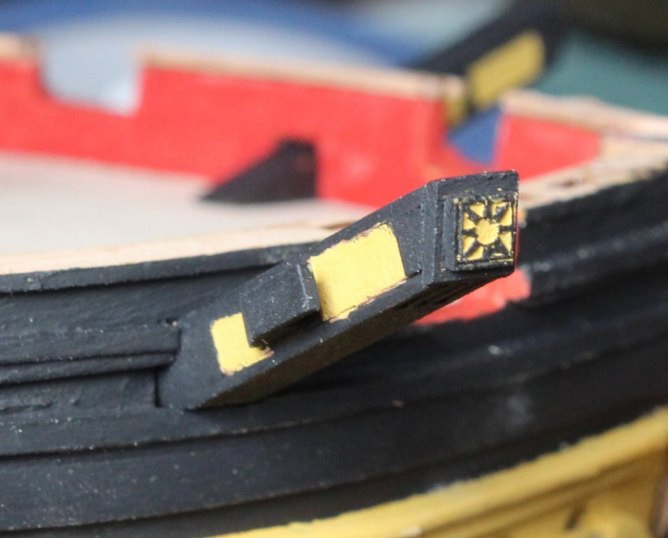
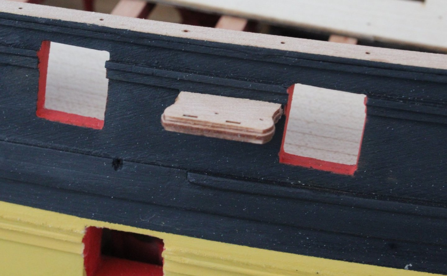
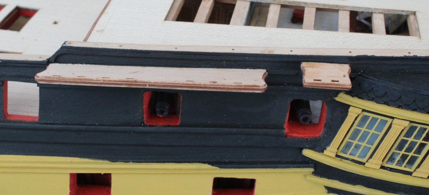
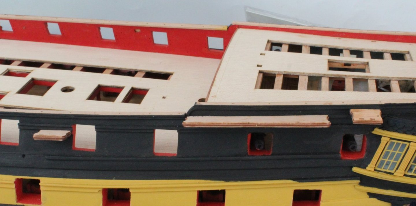
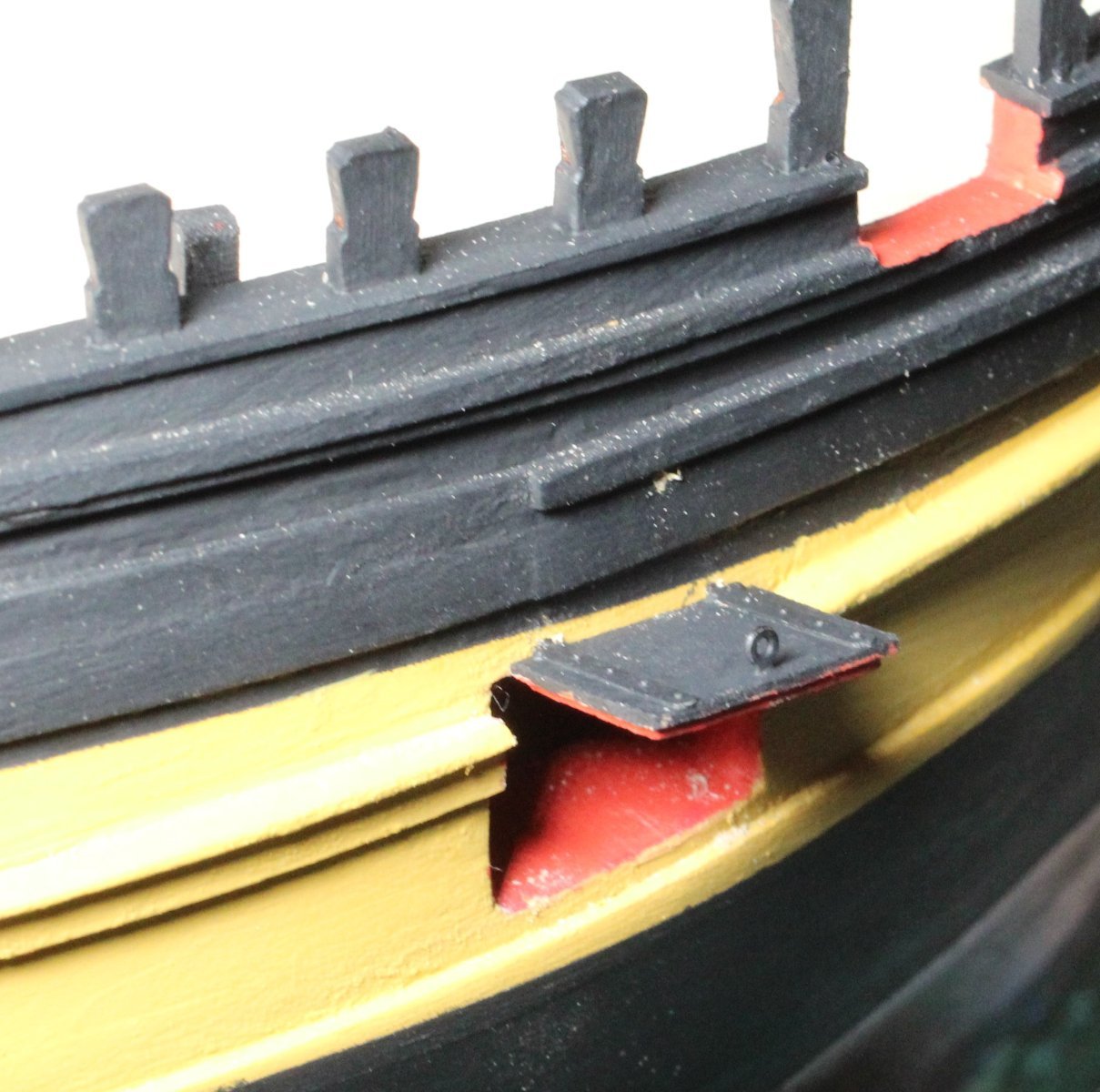
Chesstrees and Side Fenders
There is one chesstree and two side fenders to be fitted each side of the hull. The kit supplied parts required various notches cutting so the parts would fit over the rails. I took my time and regularly checked the fitting as I was creating the required notches. Once I was happy with the fit the parts were painted, noting the black and yellow hull colour bands. The parts were then glued in place. As recommended in the build manual I used a scrap length of 4mmW planking to set the distance between the two side fenders.
The hull does require a bit of cleaning to remove the unwanted debris.
-
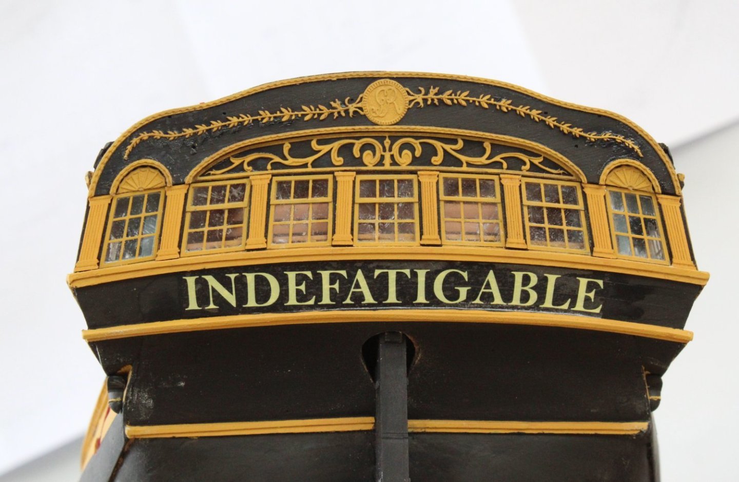
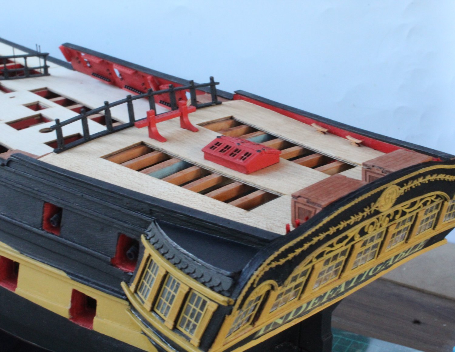
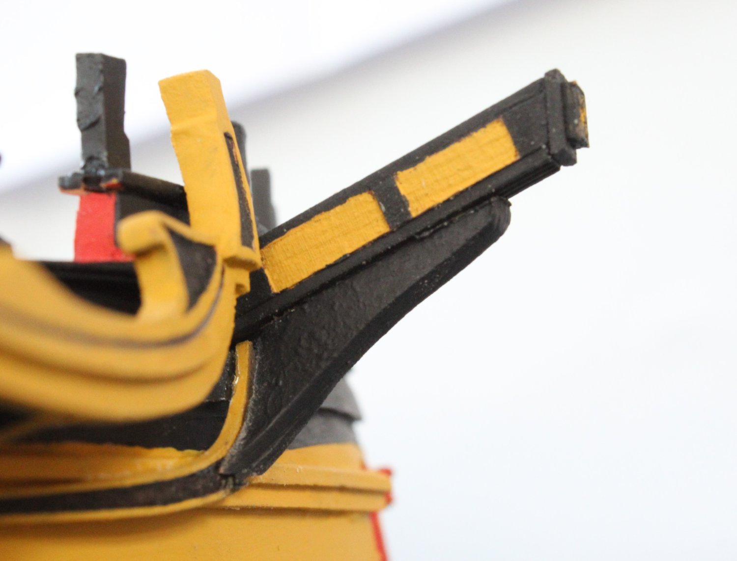
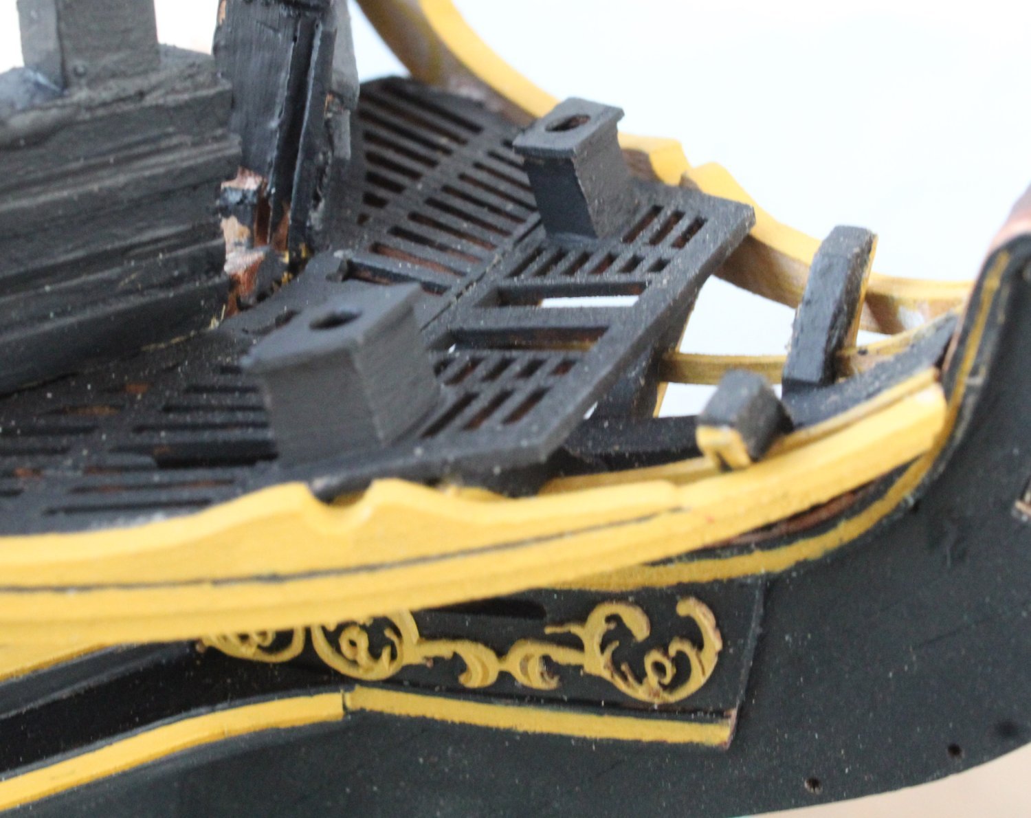
Stern Decorations
The various stern decorations patterns were painted yellow ochre and then affixed in place. I did not encounter any problems with fitting the PolyBak decorations. I did have wet and reposition the nameplate transfer as I noticed that it was slightly off centre. Overall the stern does not look too bad but Captain Pellow needs to get a crew member to clean the cabin windows.
The two rear fitting lanterns will be added later on in the build
- ECK, AJohnson, DonSangria and 5 others
-
8
-


HMS Indefatigable 1794 by Glenn-UK - FINISHED - Vanguardodel Ms - 1:64
in - Kit build logs for subjects built from 1751 - 1800
Posted
No idea, there is no where obvious. I might have to gift it to someone.