


Glenn-UK
-
Posts
3,005 -
Joined
-
Last visited
Content Type
Profiles
Forums
Gallery
Events
Posts posted by Glenn-UK
-
-
Quarterdeck Deck Beams, pillars, ships stove and lower capstan
A bit of a mixed bag sort of day with the build.
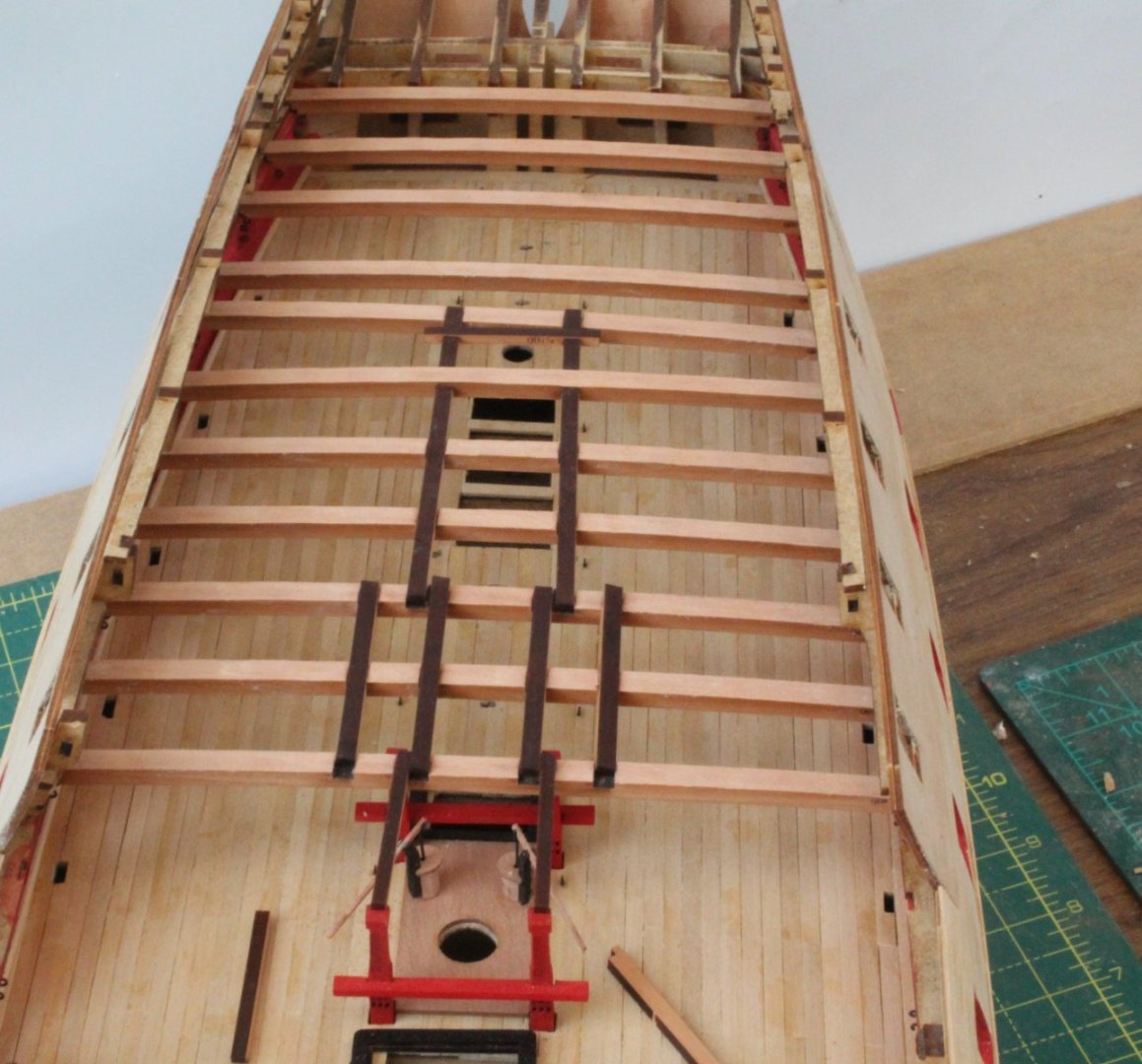
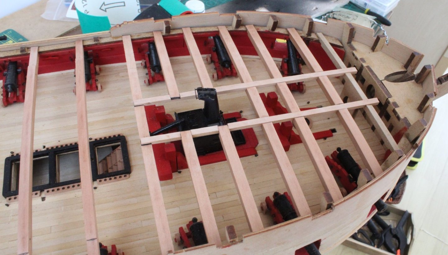
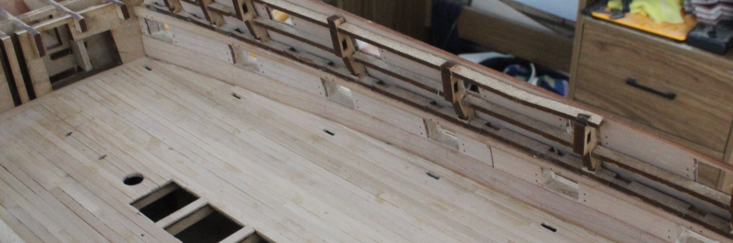
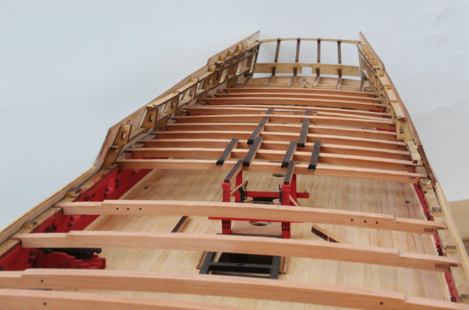
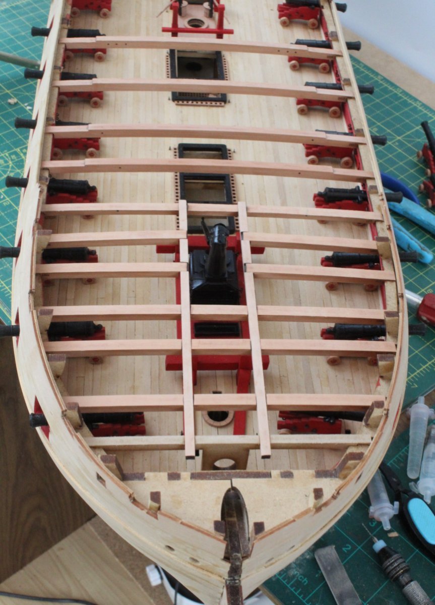
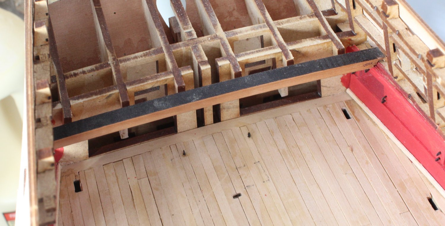
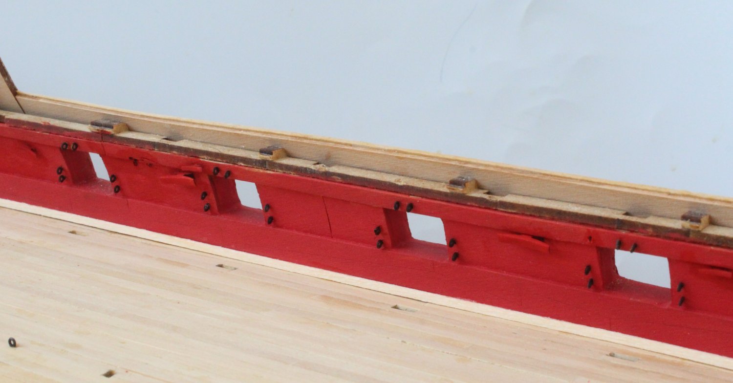
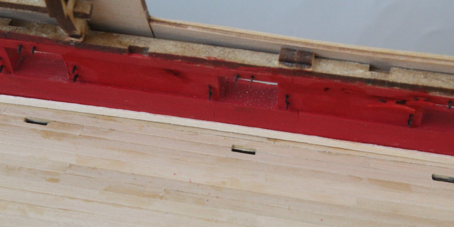
The first couple of hours this morning were spent cleaning the laser char from the quarterdeck deck beam beams and then test fitting. It was a tad tricky removing some bits of the MDF frame so the beams could be located. The beams outer edges also needed a bit of shaping.
With all the standard quarterdeck deck beams in place (QD9 to QD19) I did a trial fit of the deck beam interlocking patterns. I am happy with how everything seems to fit. I still need to remove the laser char from the deck beam interlocking patterns before fitting. You may notice that a couple of the deck beams are not correctly seated in the photos below. There is build process required for the remaining quarterdeck deck beam (QD08) which still needs to be done.

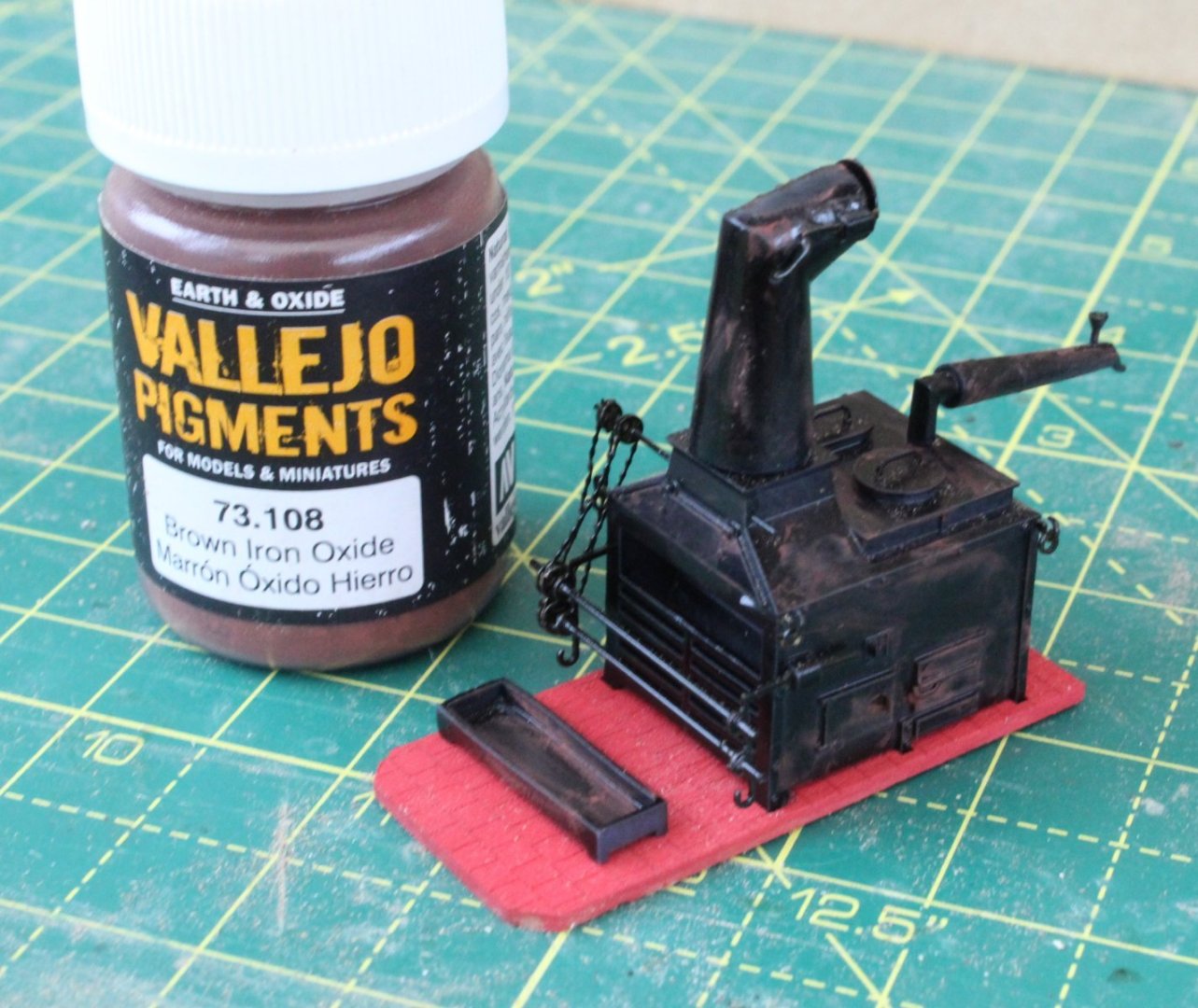
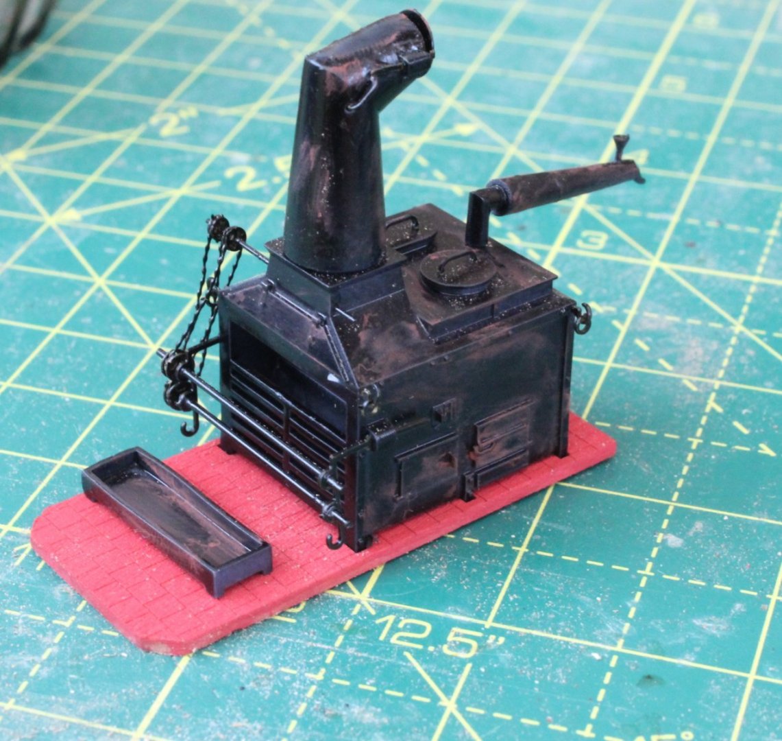
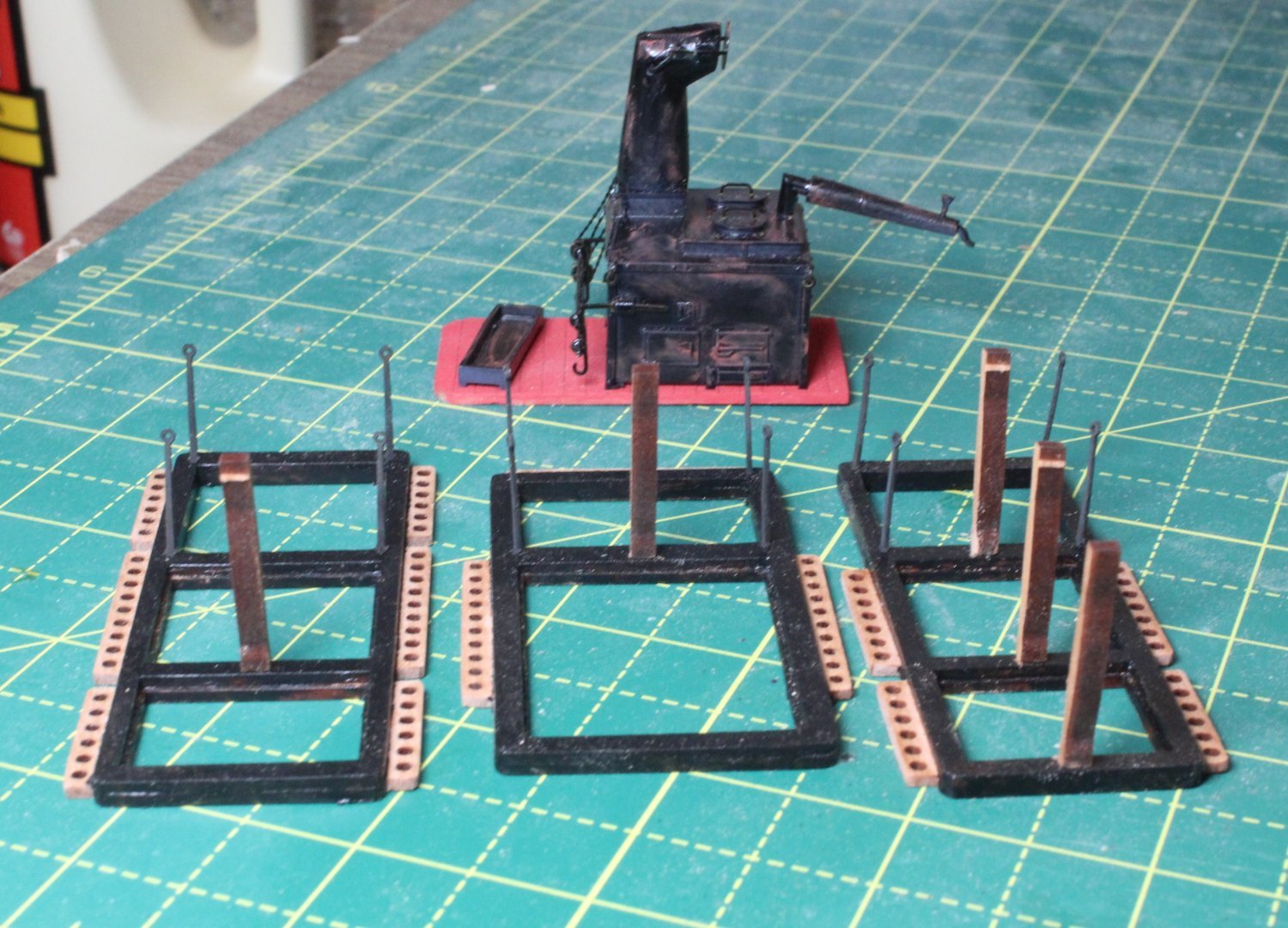
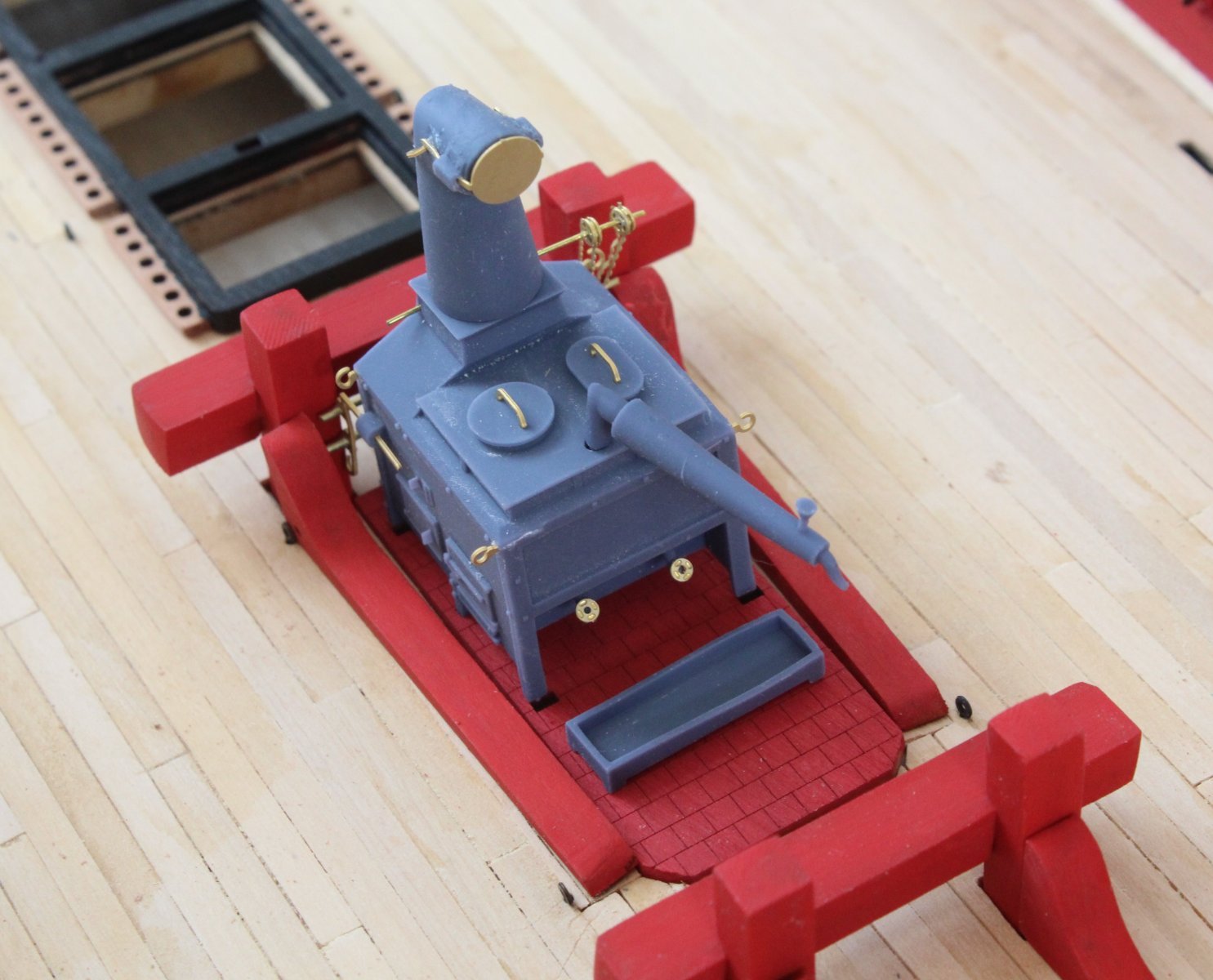
Next I decided to add some weathering to the ships stove using a brown iron oxide pigment. It looks a well used stove now.
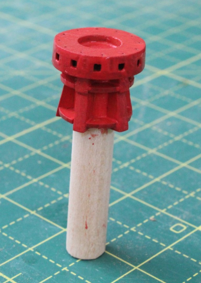
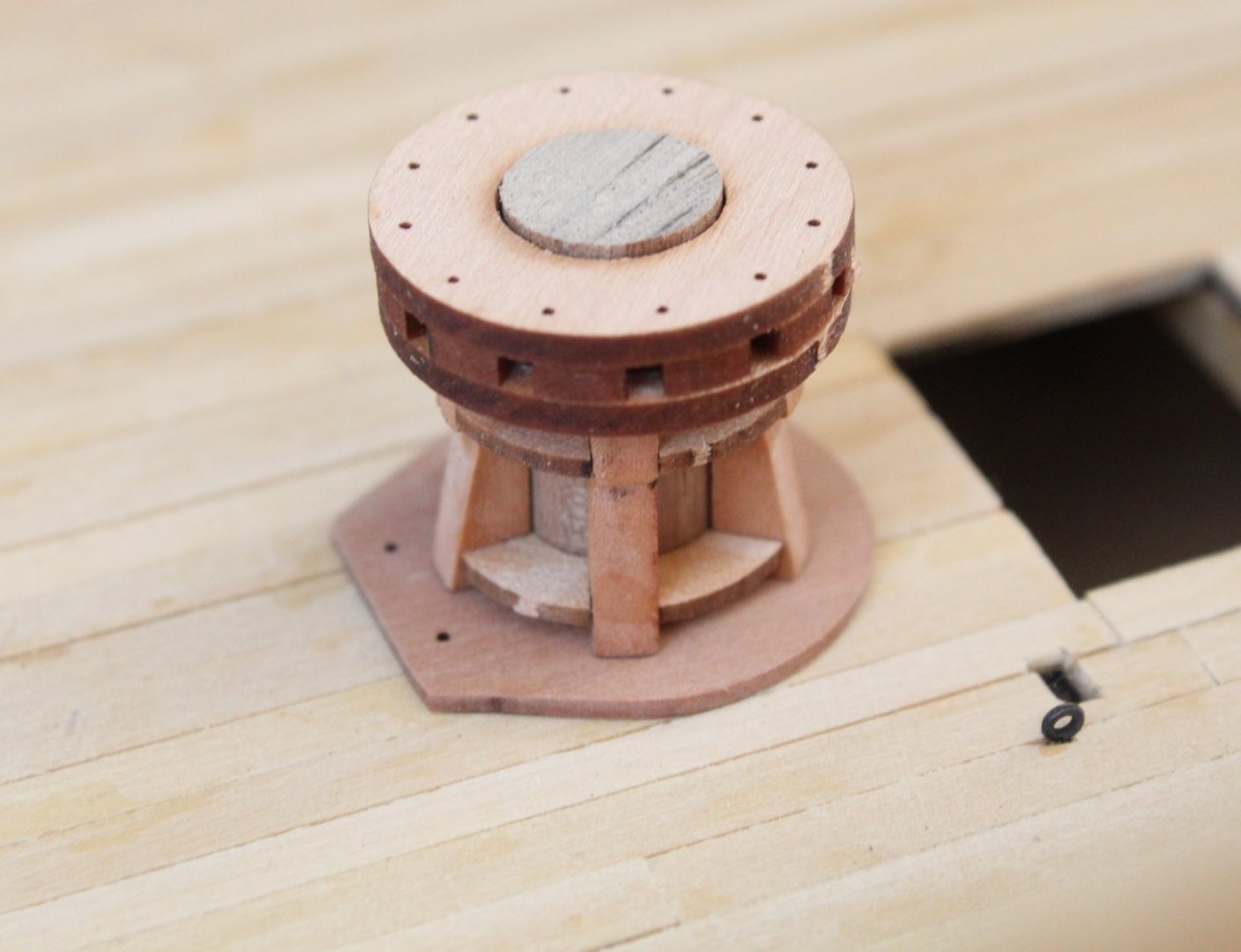
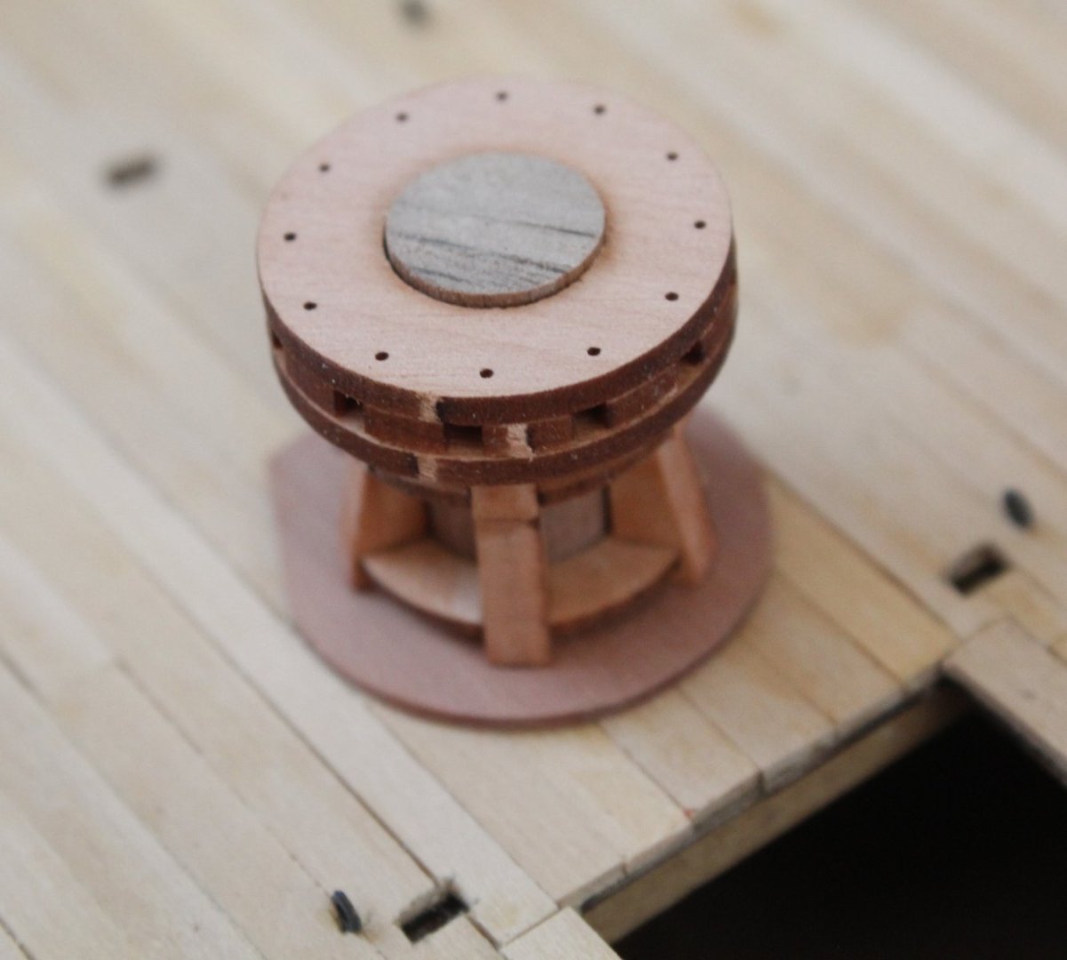
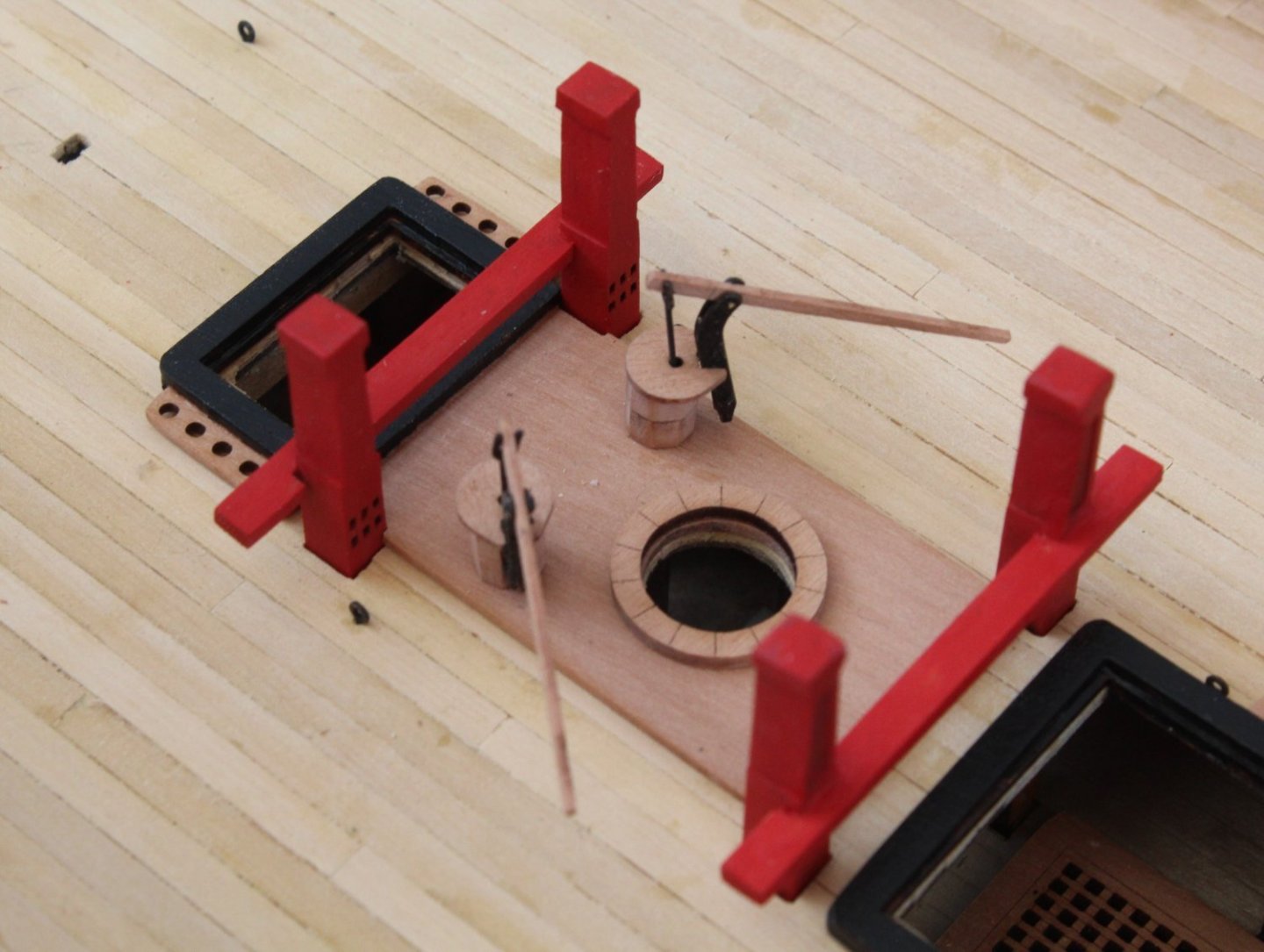
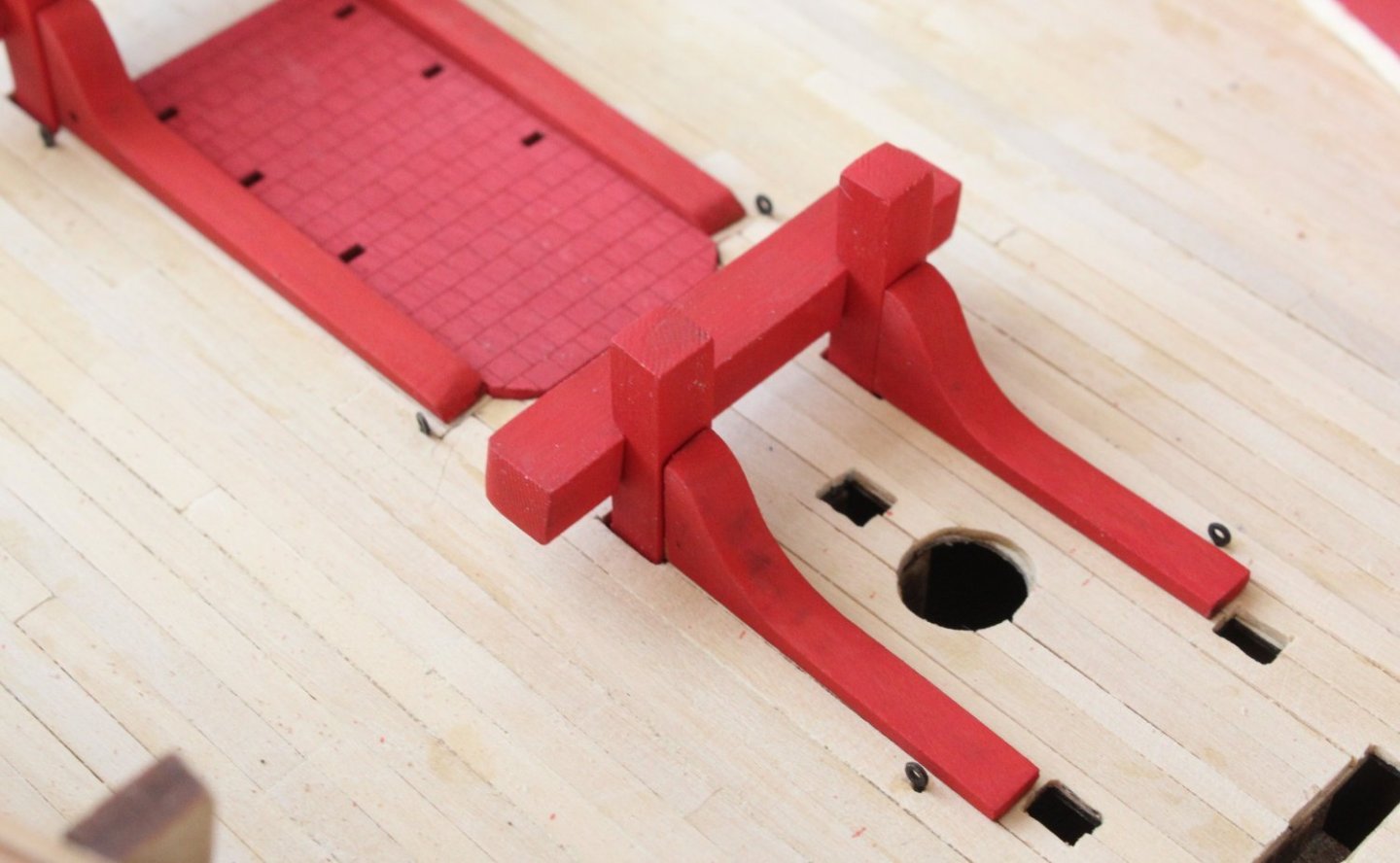
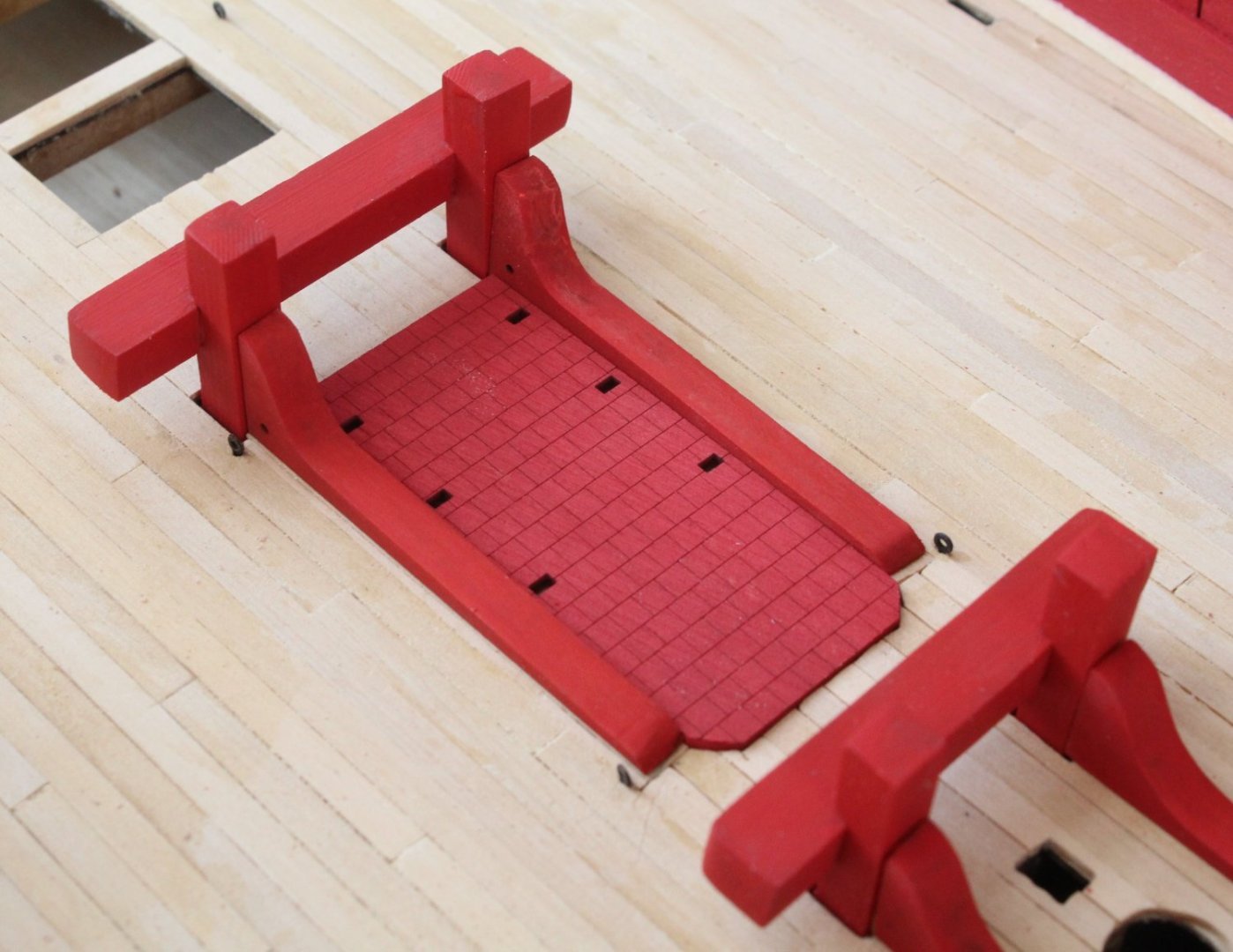
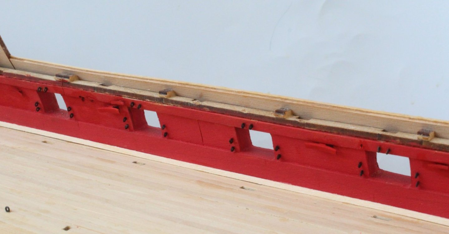
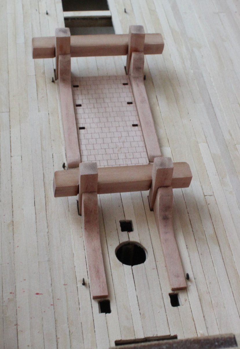
After applying a WOP to the lower capstan assembly it was given a coat of flat red paint. The paint is still drying in the following photo. I will apply a couple more coats before it ready to be fitted to the gundeck
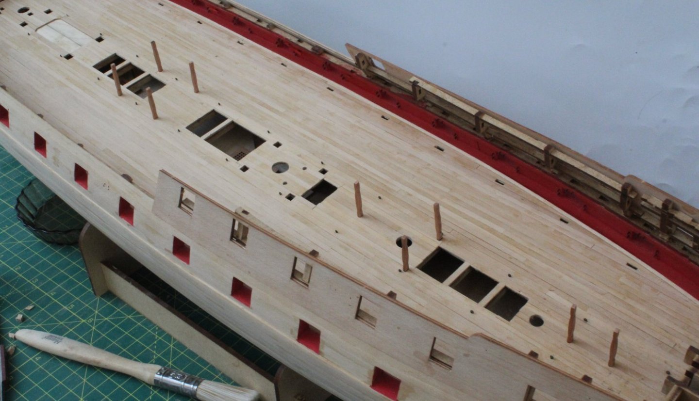
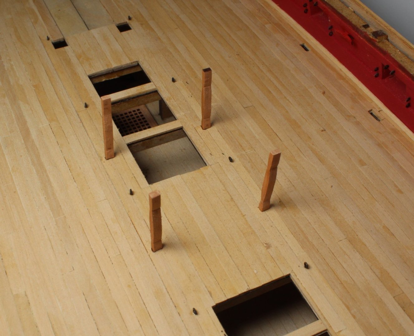
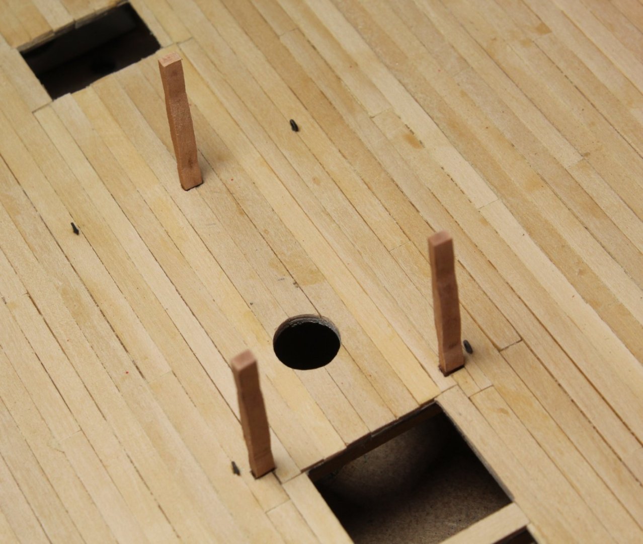
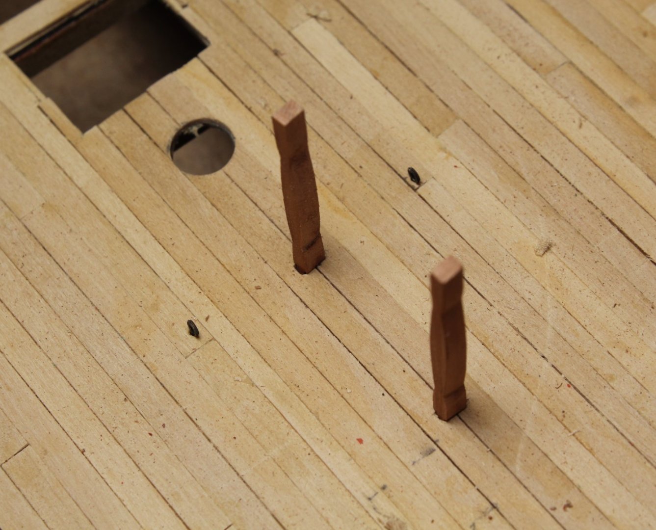
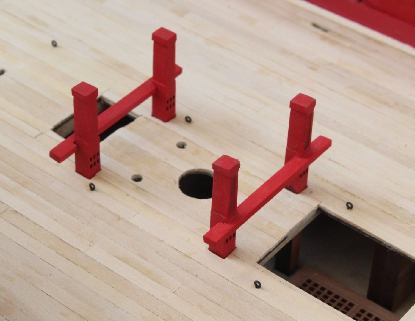
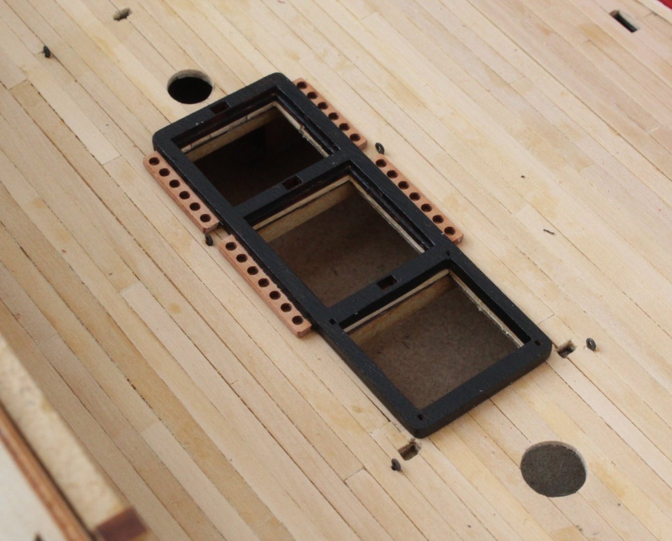
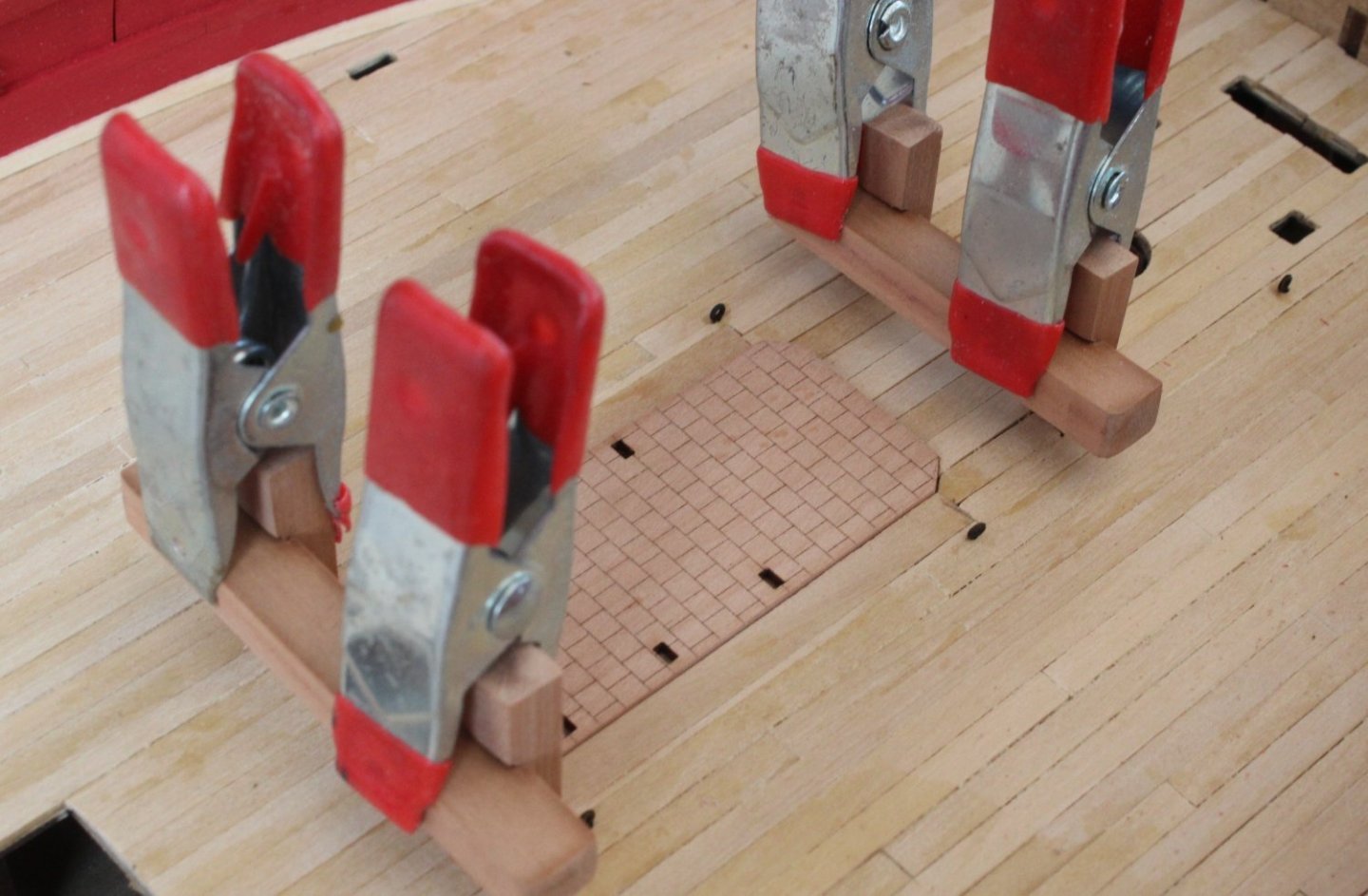
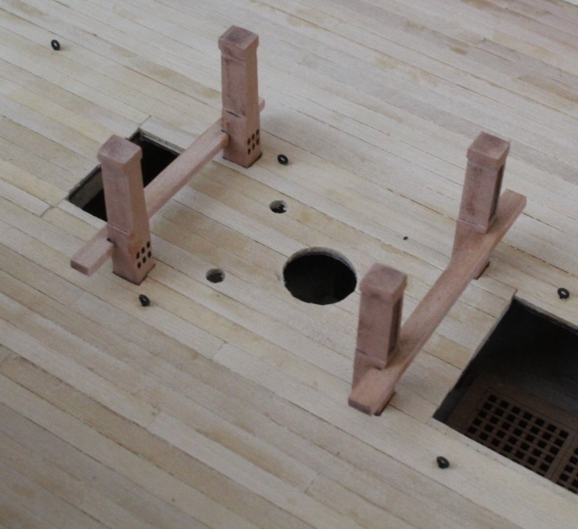
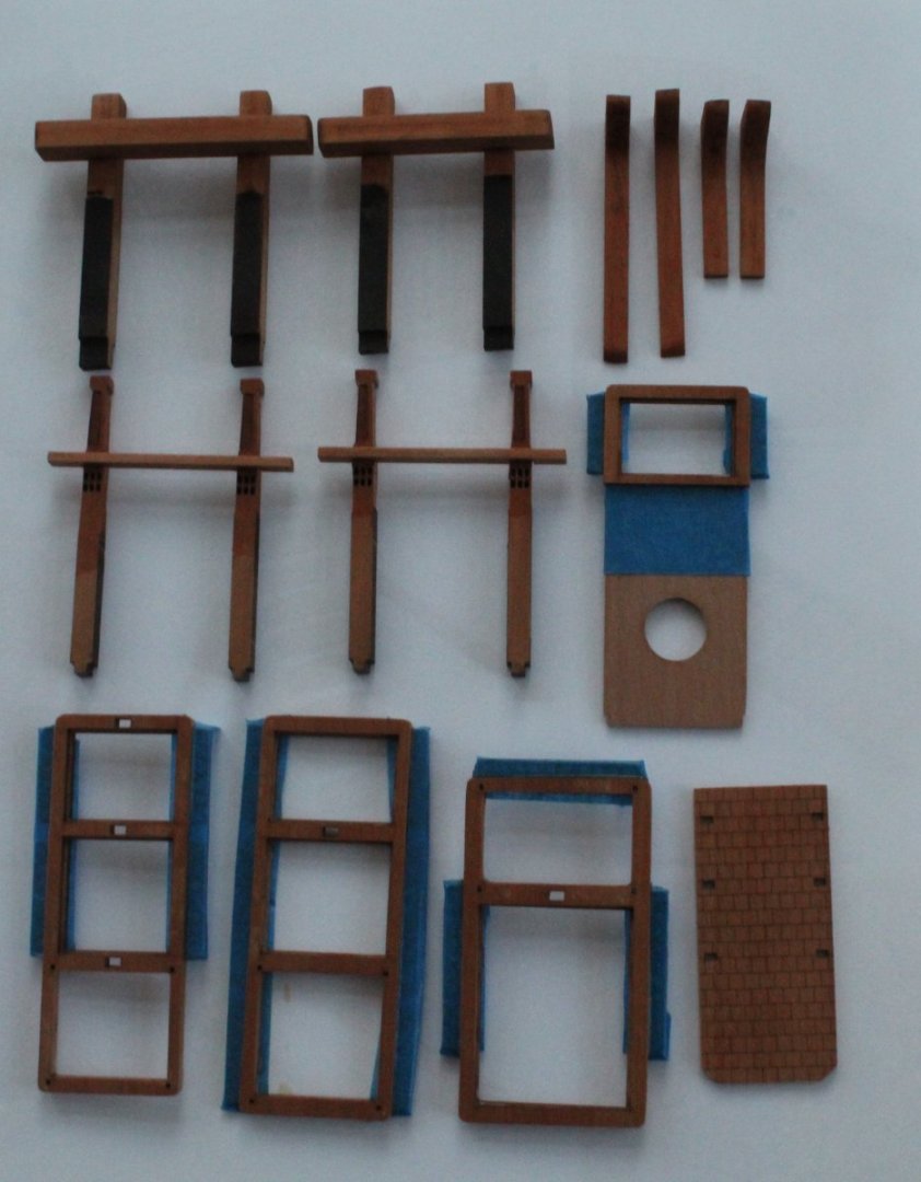
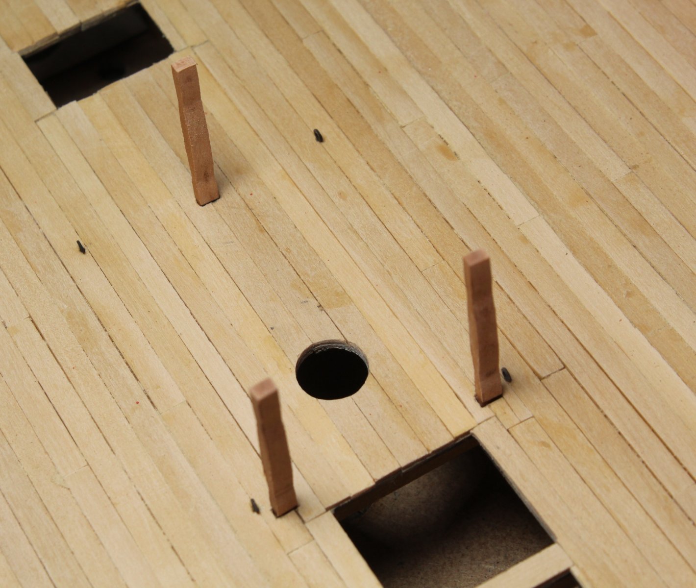
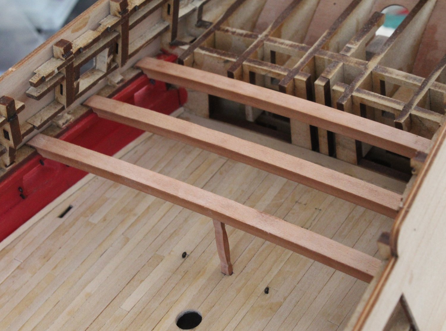
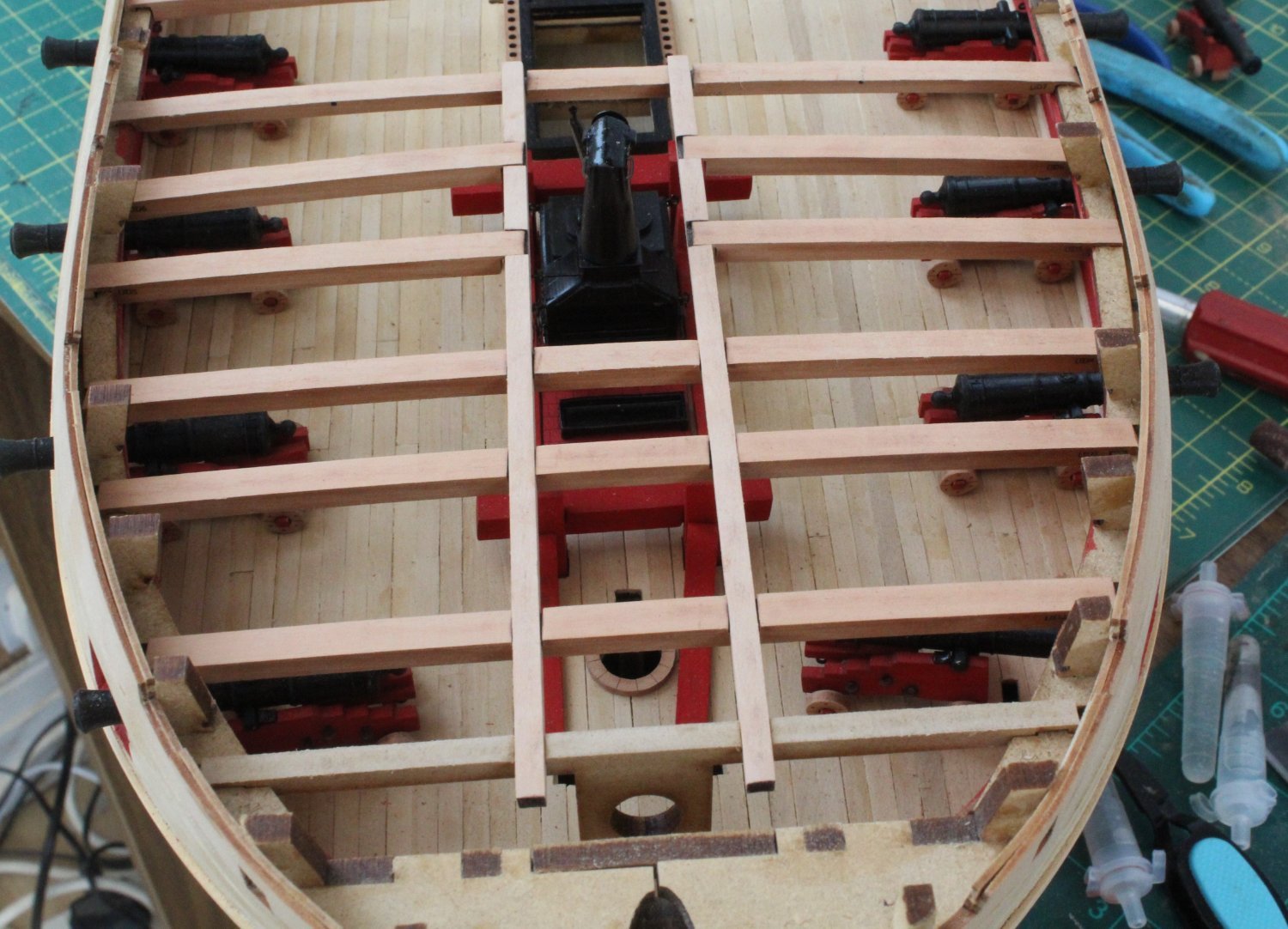
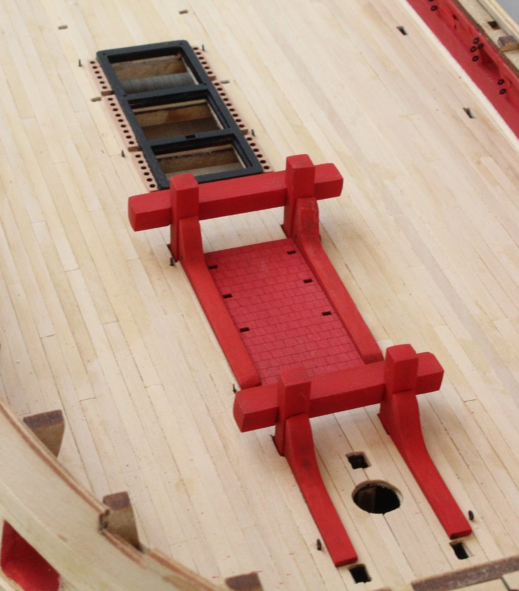
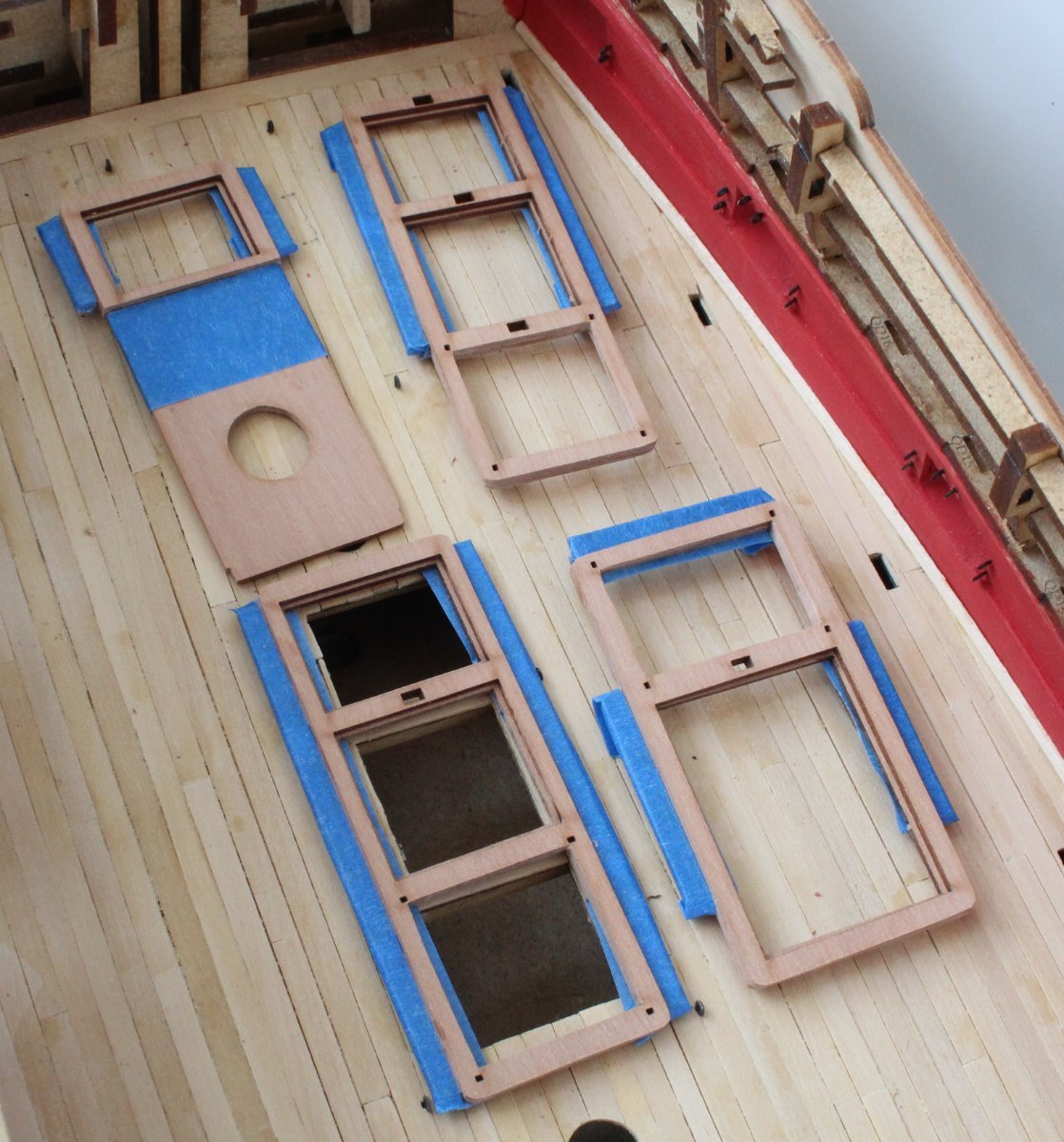
Next I test fitted the stanchions and deck pillars to the various hatches. I have always found it easier to check the fitting of these items prior fitting the hatches to the gundeck. The deck pillars may need to be trimmed so they will sit under the deck beams. They will be trimmed and fitted when it is time to add the various deck beams.
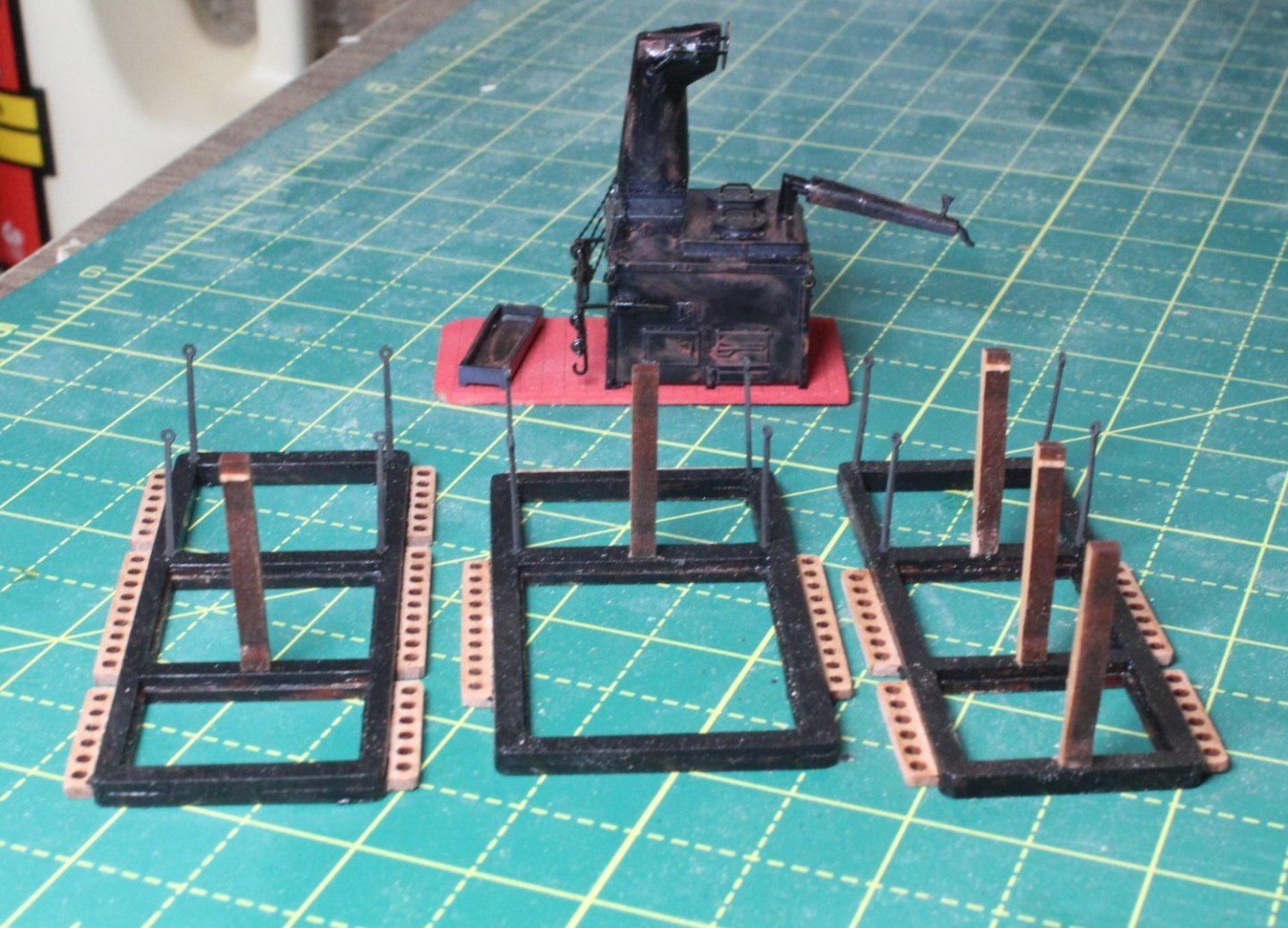
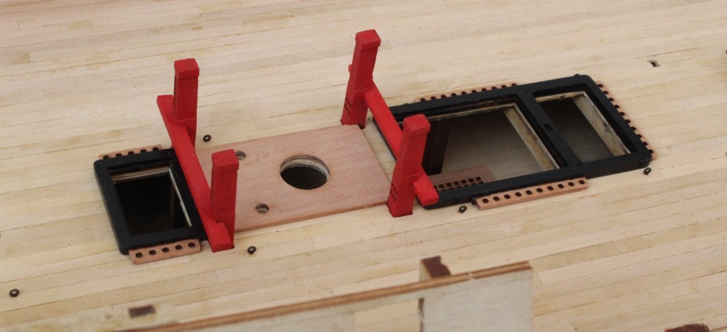
Finally I checked the fitting of gundeck pillars. Again these will be trimmed as necessary and fitted when the deck beams are added.
-
Excellent workmanship Maurice.
- Blue Ensign, mtaylor and ECK
-
 2
2
-
 1
1
-
Lower Capstan and Quarterdeck Beams
The replacement chokes for the lower capstan arrived this afternoon. It took no effort to build the capstan. Many thanks to @chris watton for his excellent help and support. Here is a couple of photos of the dry fit on the gun deck, prior to painting. The inner dowel will need to be trimmed a bit also.
Progress on test fitting the quarterdeck deck beam is slow and steady. As can be seen below the deck pillars are checked to ensure they are the right height to ensure the deck is level.


-
Deck Beams
Whilst I wait for a couple of replacement capstan chokes to arrive I thought I would move on to cleaning up and test fitting the forecastle and quarterdeck deck beams.
Some of the forecastle deck beams outer edges required a little bit of shaping to match the bulwarks curve. I then used my rotary tool to remove the laser char from the deck beam top edges following by a fine sanding stick. The beams were then test fitted and everything looks good.


As can be seen below I have painted the ships stove black. I will add a little bit of weather before it is fitted,
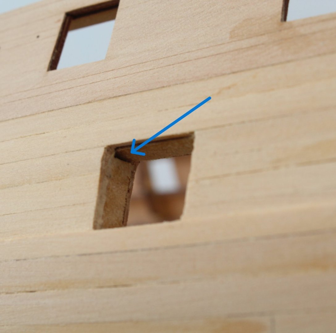
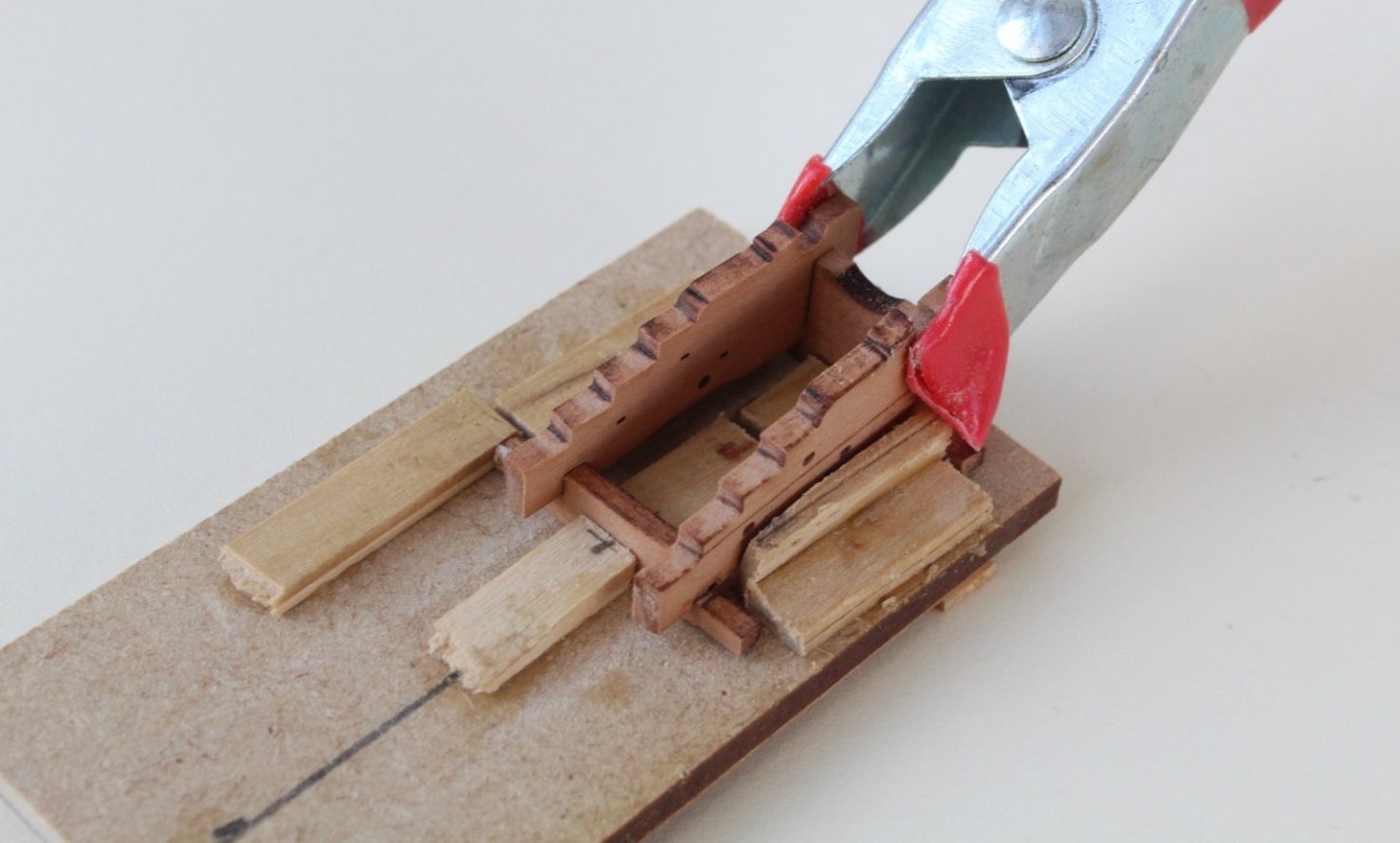
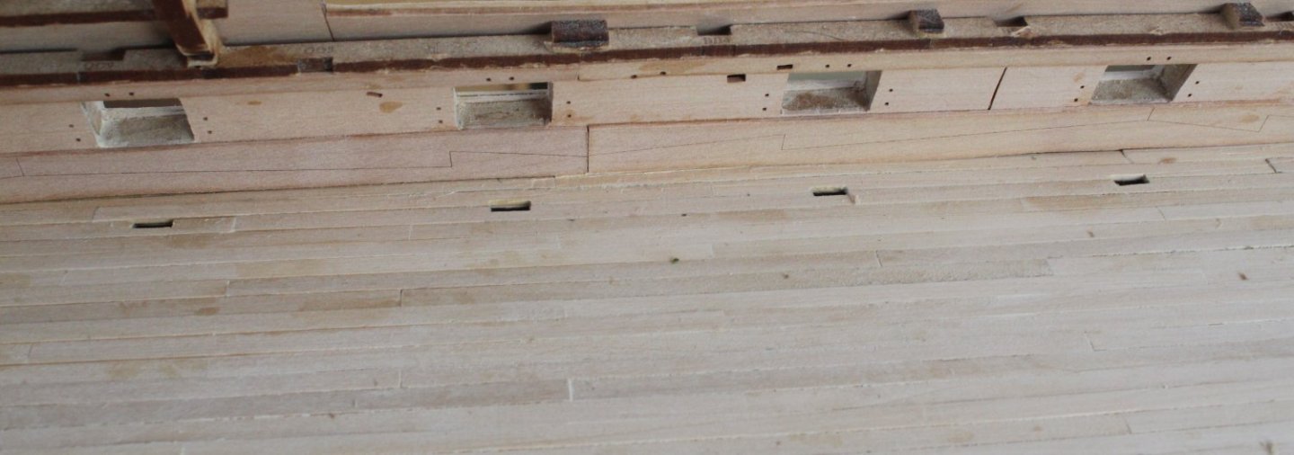
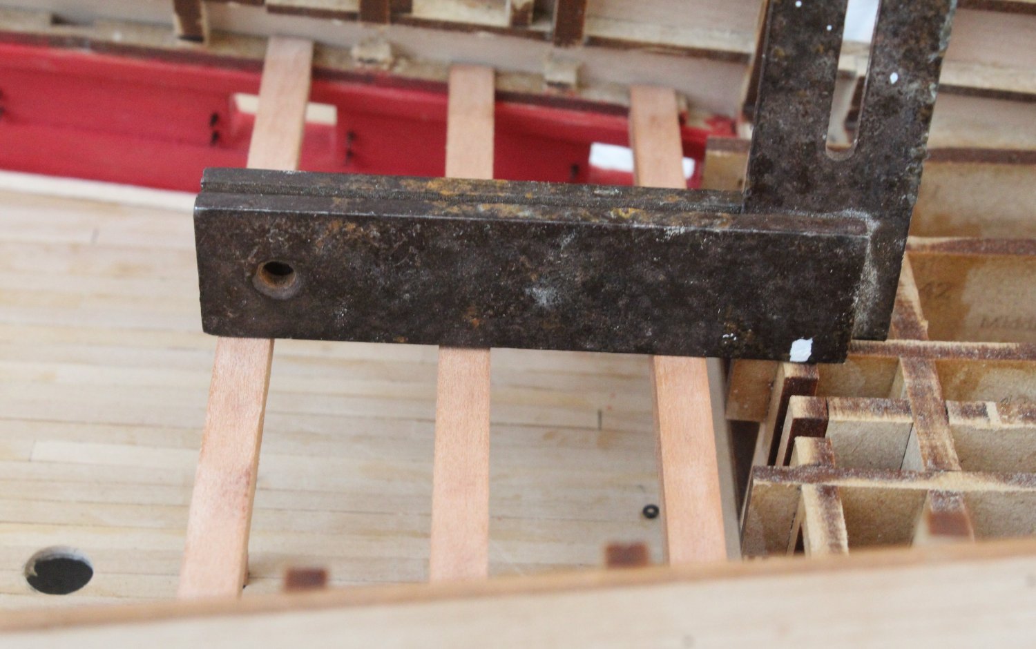
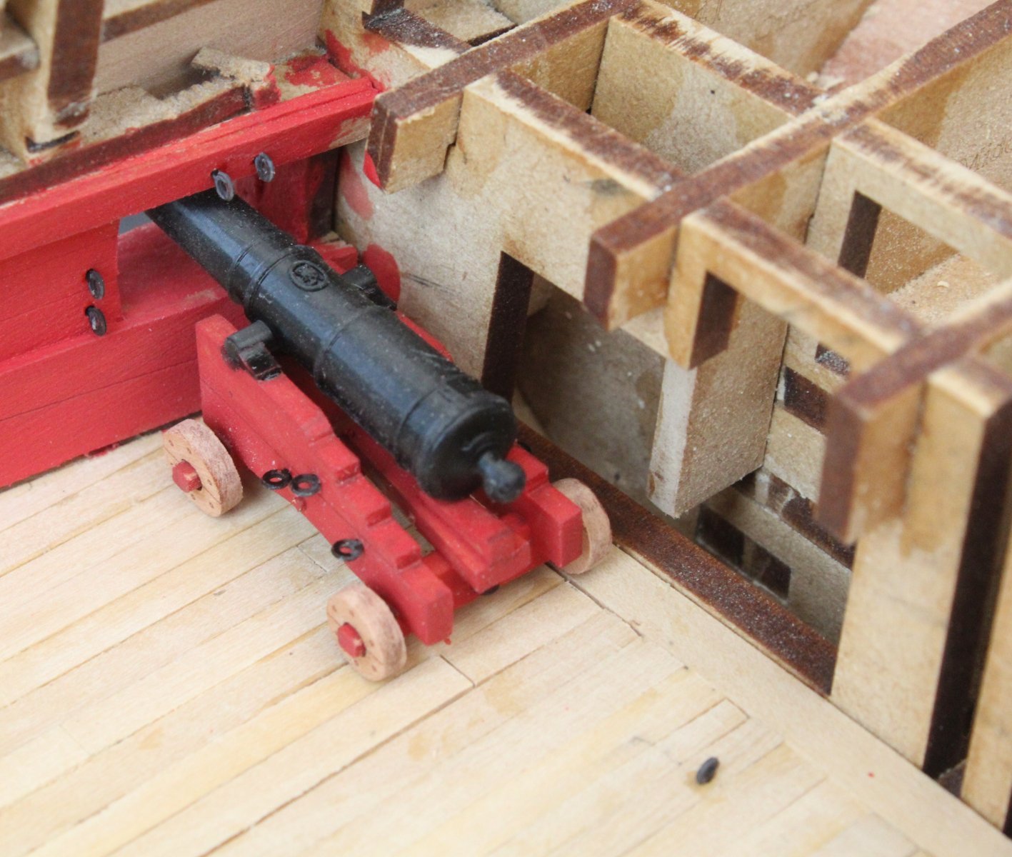
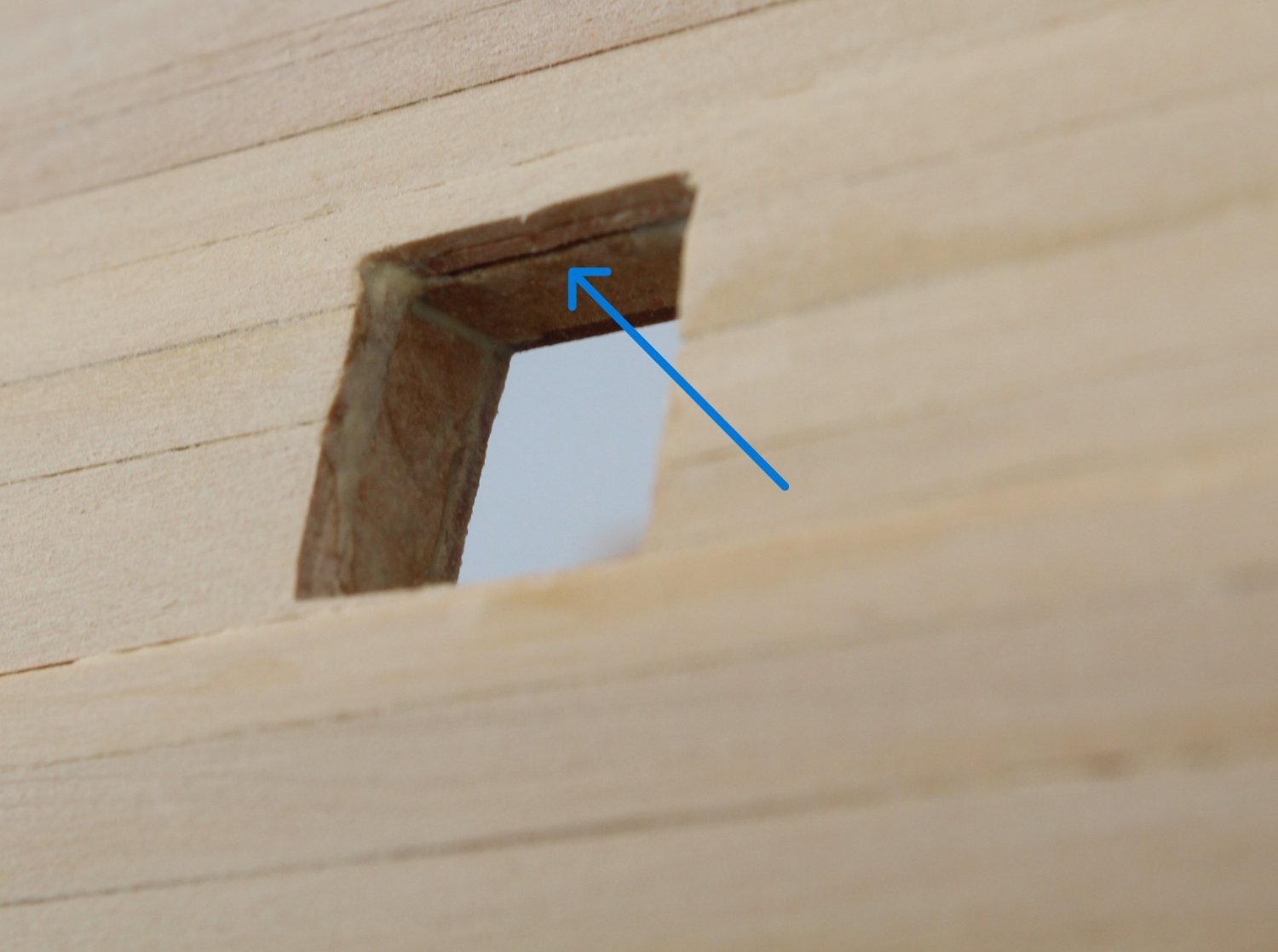
As I started to look at adding the quarterdeck deck beams there did not seem to be a way to get any of the beams to fit due to the MDF frames getting in the way. Thankfully there is a solution as the following note was included in the build manual with an example photo.
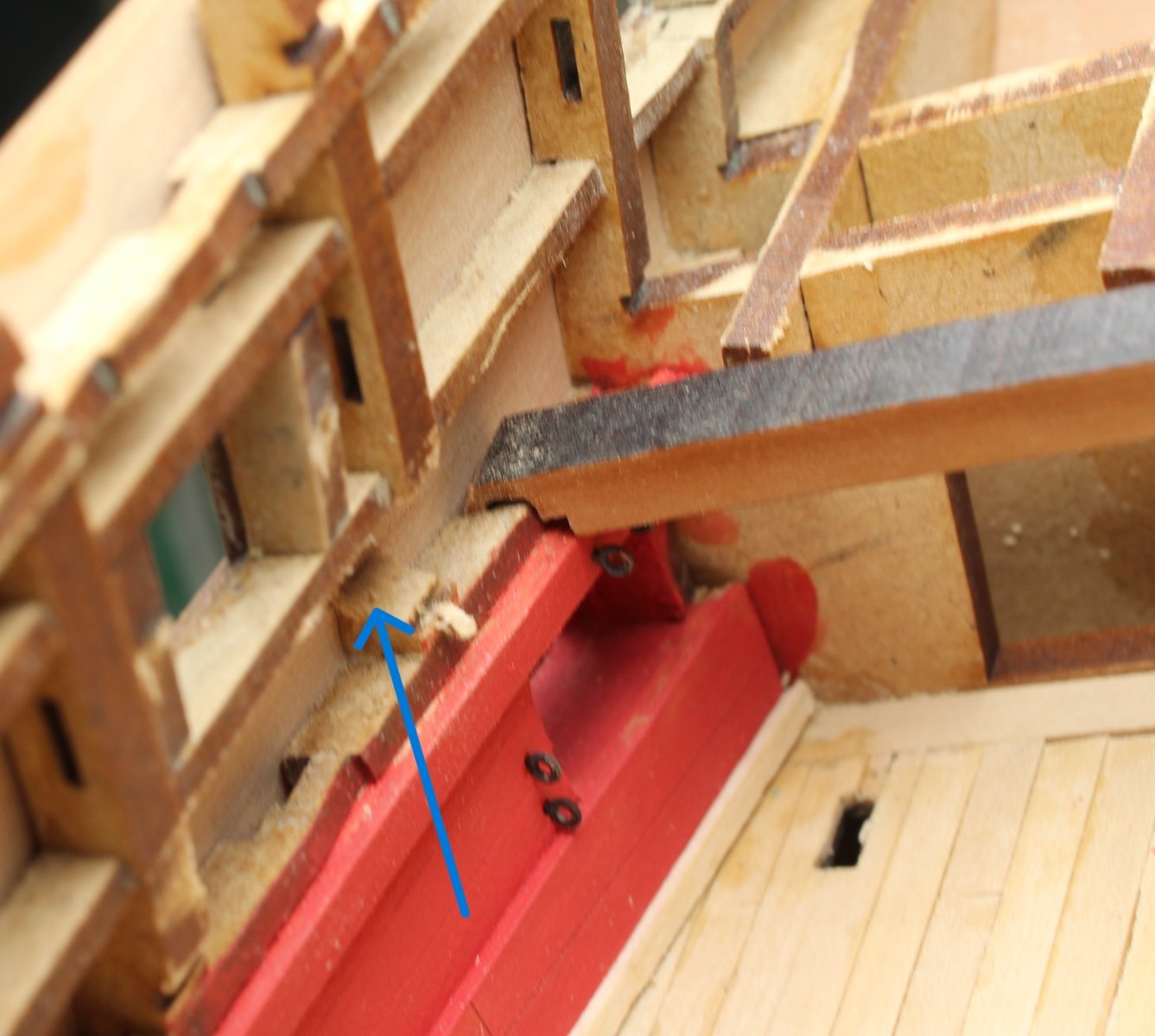
It is perfectly fine to selectively cut into and remove sections of the MDF frame so the beam can be manoeuvred into position.
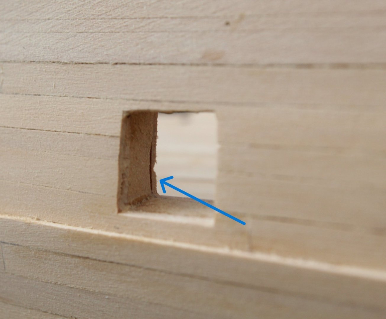
Making a few careful cuts with my small hand held razor saw a small section of the first MDF frame was removed as can be seen in the photo below, as shown by the blue arrow

After a bit of work to shape the outer edges the first quarterdeck deck beam (QD19) was slotted in to place, noting the laser char still needs to be removed from the top edge.

-
-
-
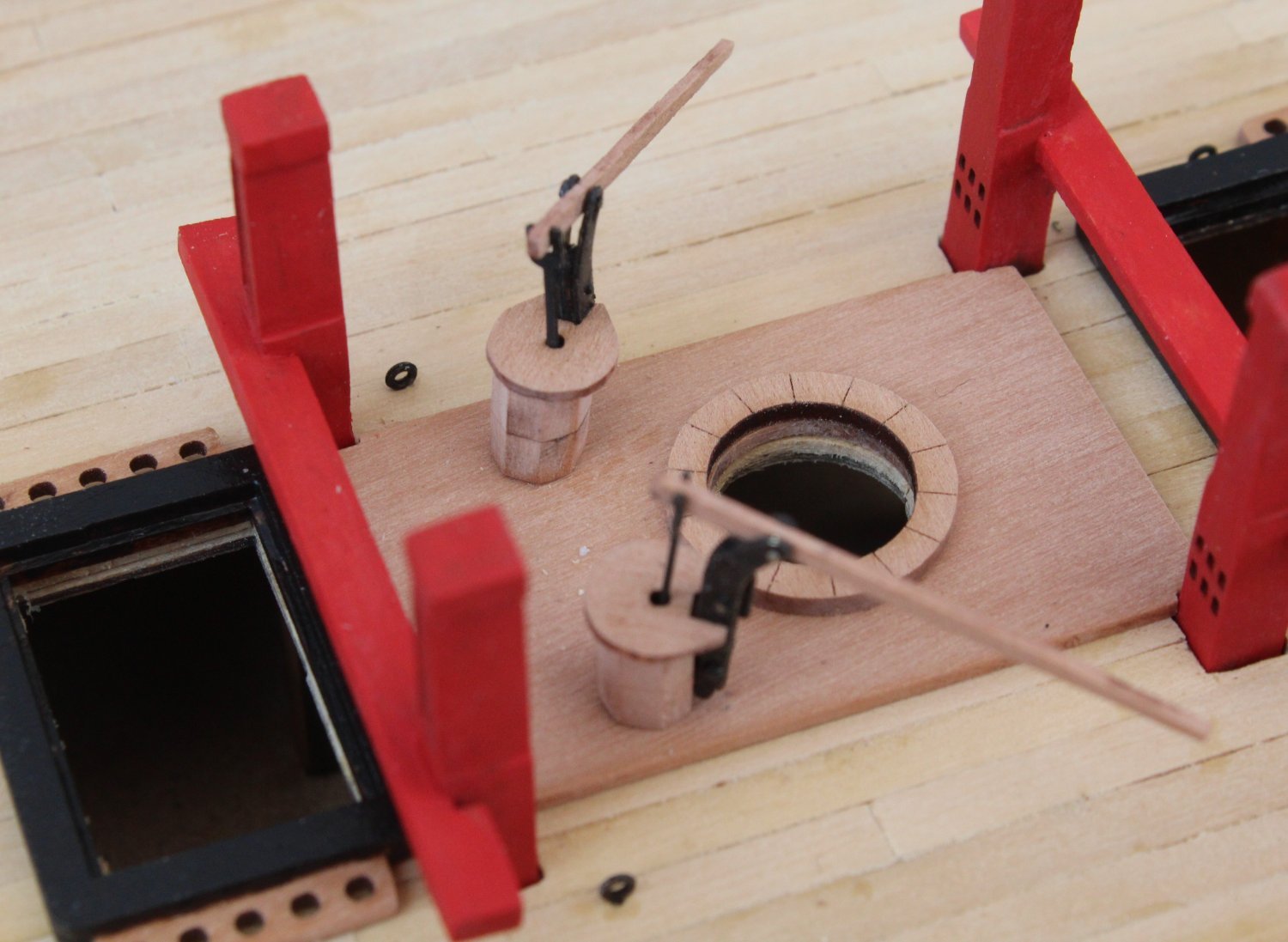
Hand Pumps and Stove
The final three gun deck items to build are the lower capstan, the two hand pumps and the ships stove.
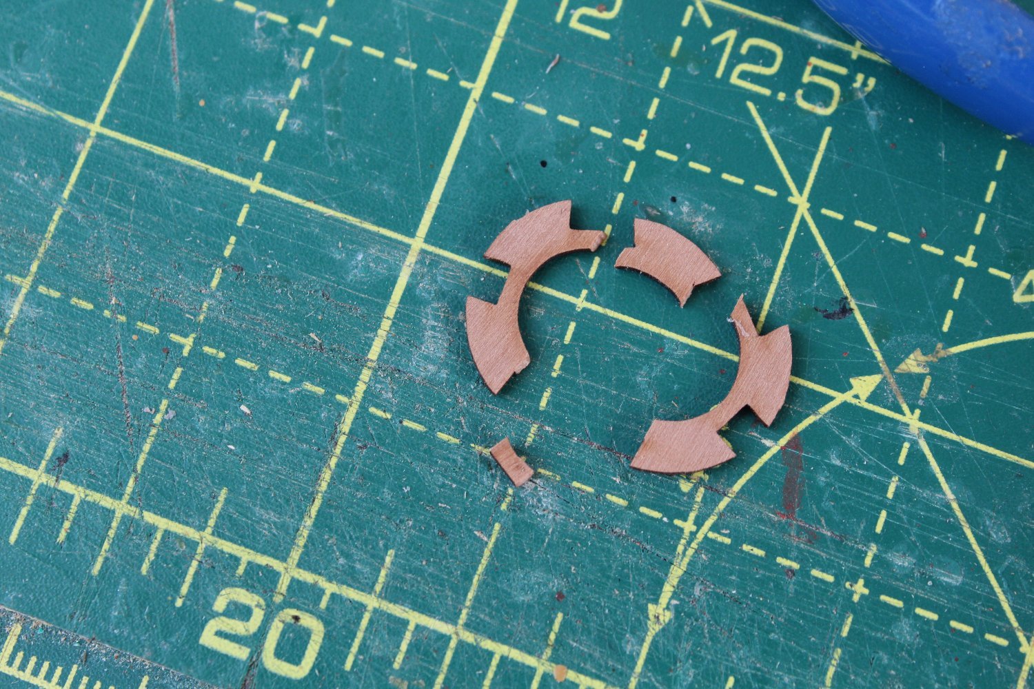
I had a bit of a disaster with the lower capstan when I managed to break both chokes when I was adding the drumhead. It was my own stupid fault by applying to much pressure when attempting to get everything to line up. Hopefully there is a solution in the offering which may take a few days to sort out. As you can see below one choke in particular has seen much better days.

Moving on to the two hand pumps I thought I would detail my construction process in a bit more detail.
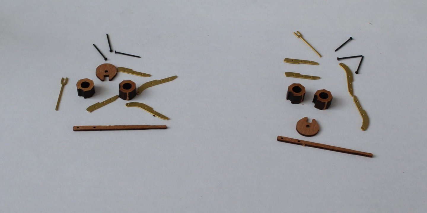
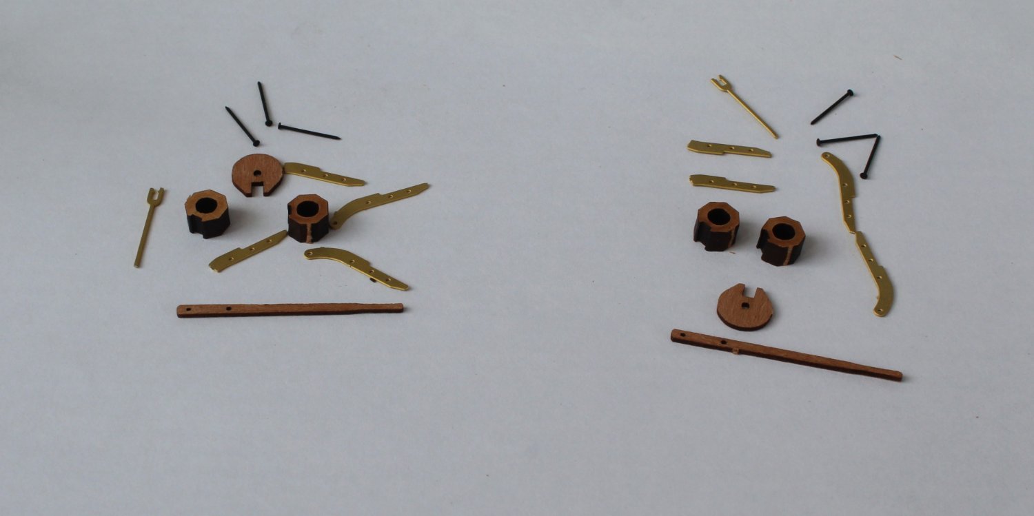
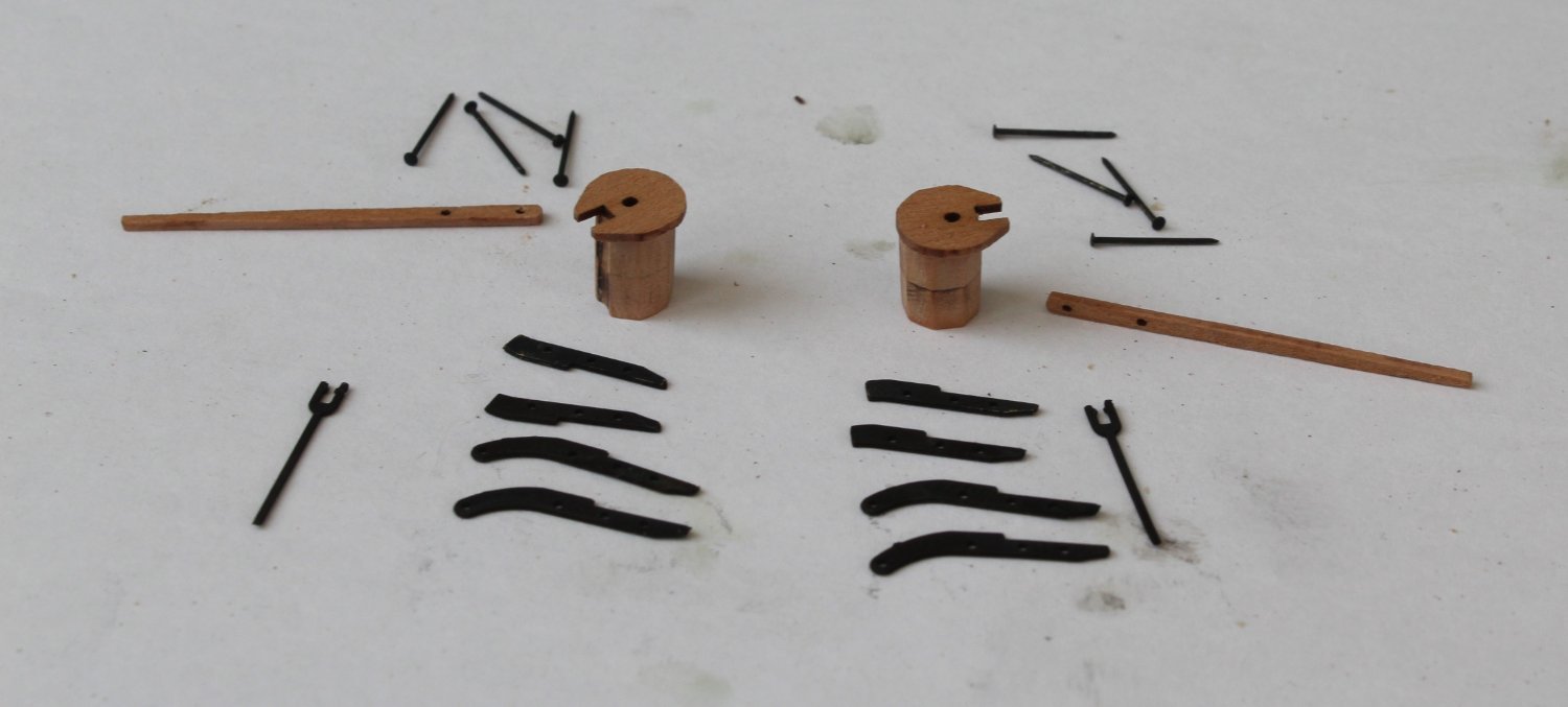
Step 1 - Assemble the raw materials
I have only shown three pins per hand pump in the photo below but 4 pins per hand pump are actually required.
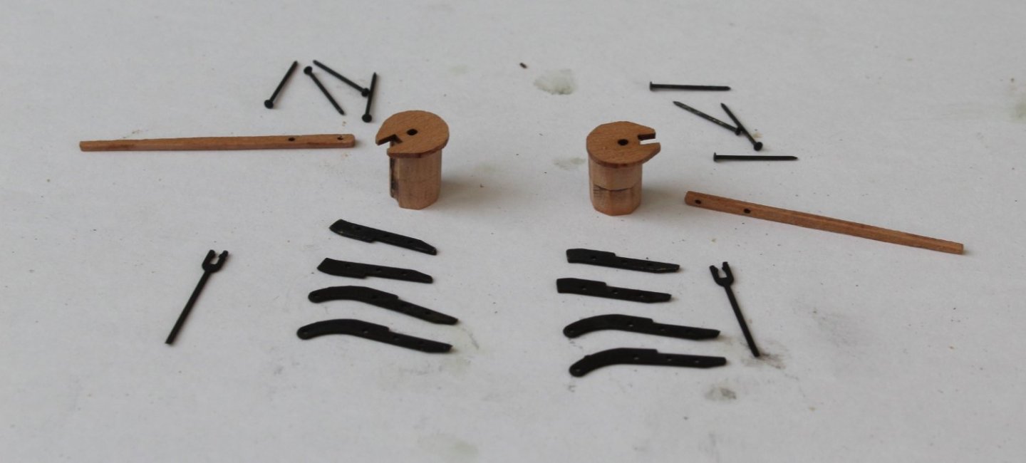
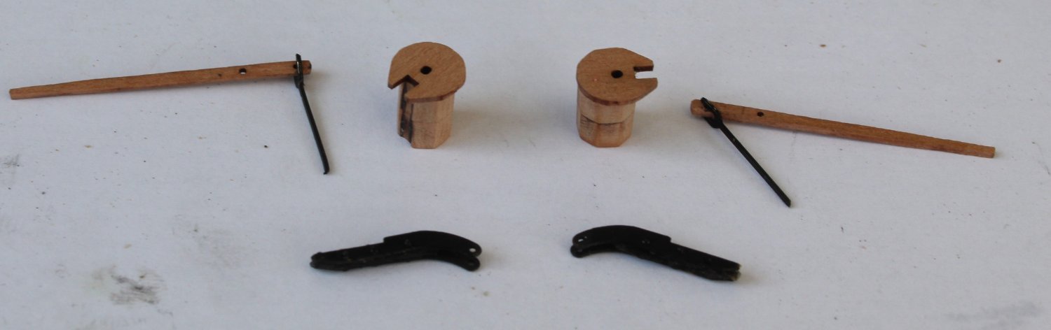
Step 2 - Perform a basic dry fit of the various items
I am happy that everything looks good at this stage so I can move forward with the construction.

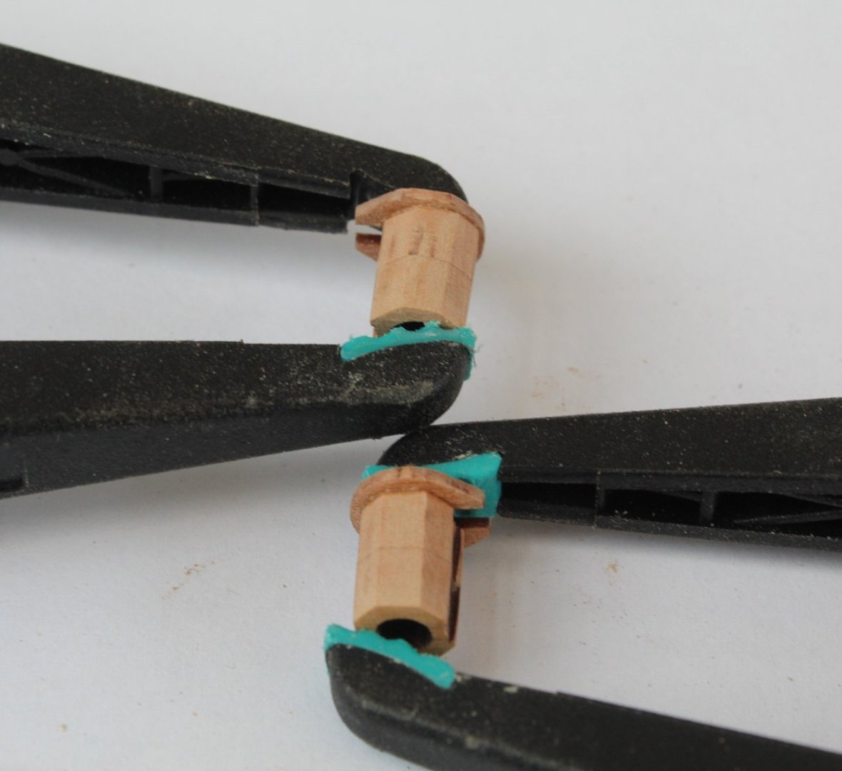
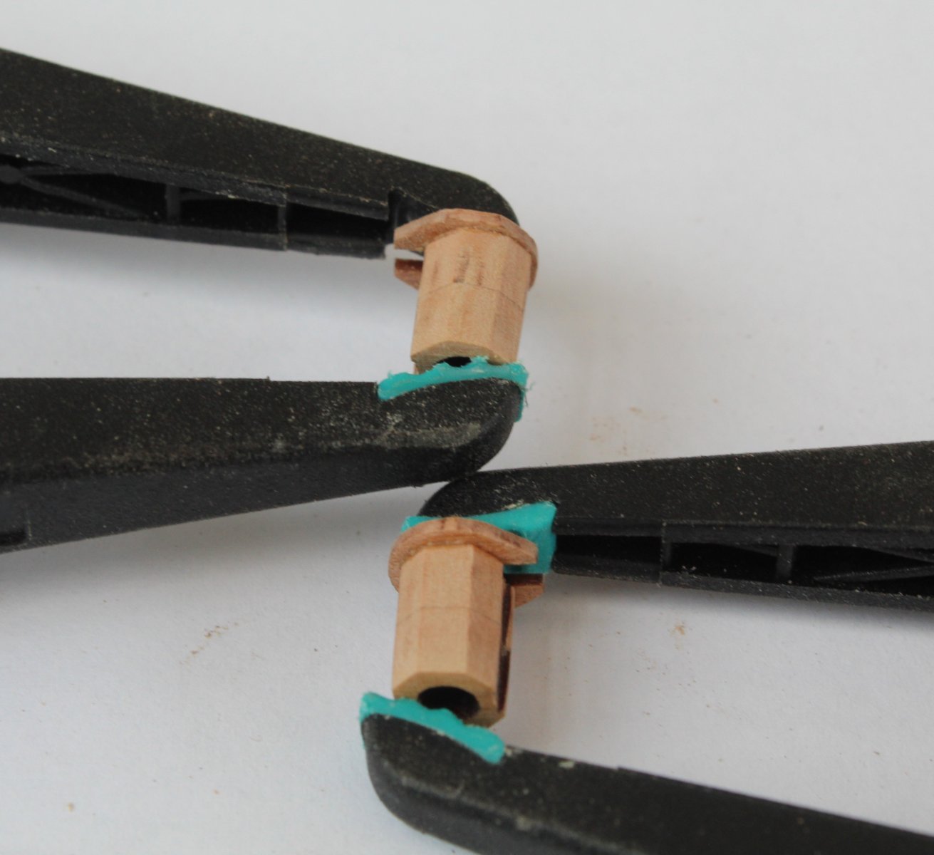
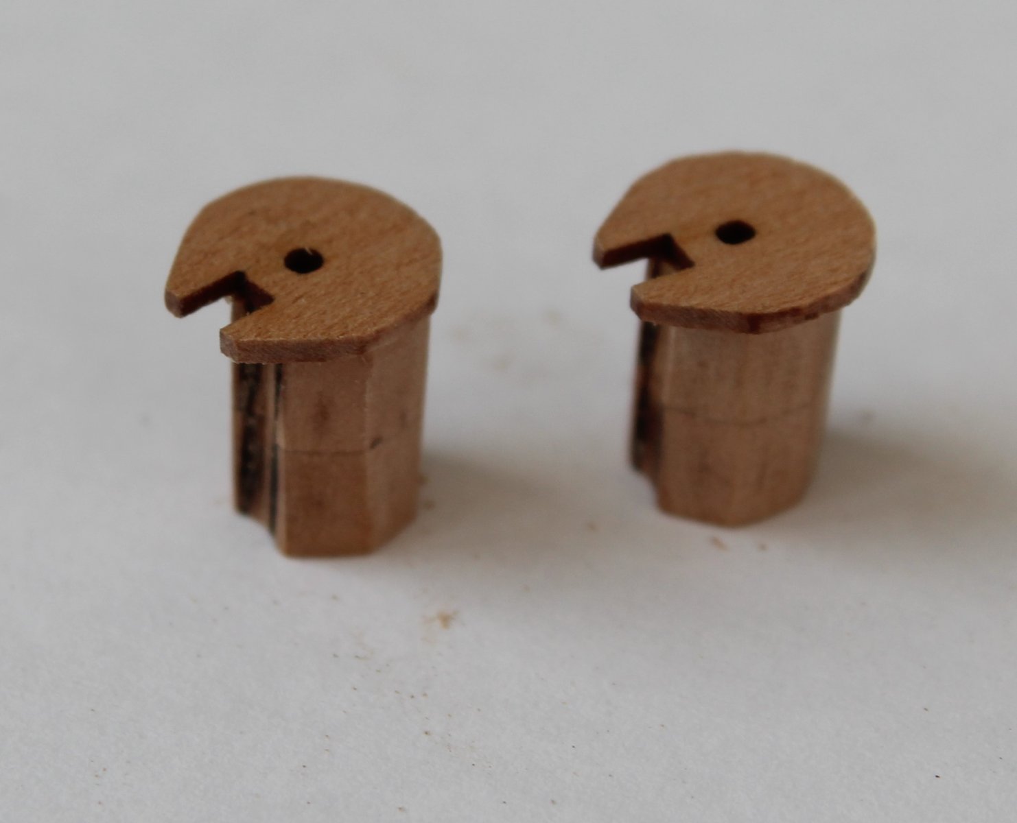
Step 3 - Glue the wooden parts together
It is important to remove the laser char from the visible edges, which I did before gluing the top cap in place.

Step 4 - Clean and Blacken the PE parts
The PE parts were soaked in acetone and then in hot soapy water a couple of times. The parts were then placed in a blackening solution. The assembly is now ready for the next task.
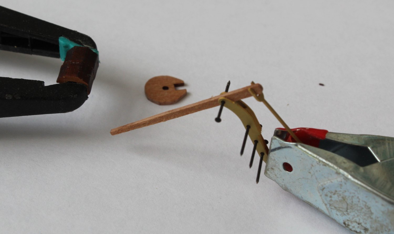
Step 5 - Assembly the pump handle
This was a two part task, the 4 main PE parts were glued together (ca glue) using 3 pins per assembly. It was then a simple job to add the handles to the pump body.

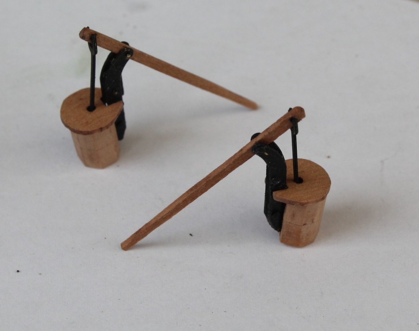
Step 6 - Dry fit the completed assembly on the gun deck
A length of dowel was added to the pump base, and the completed pumps were then positioned on the gun deck.

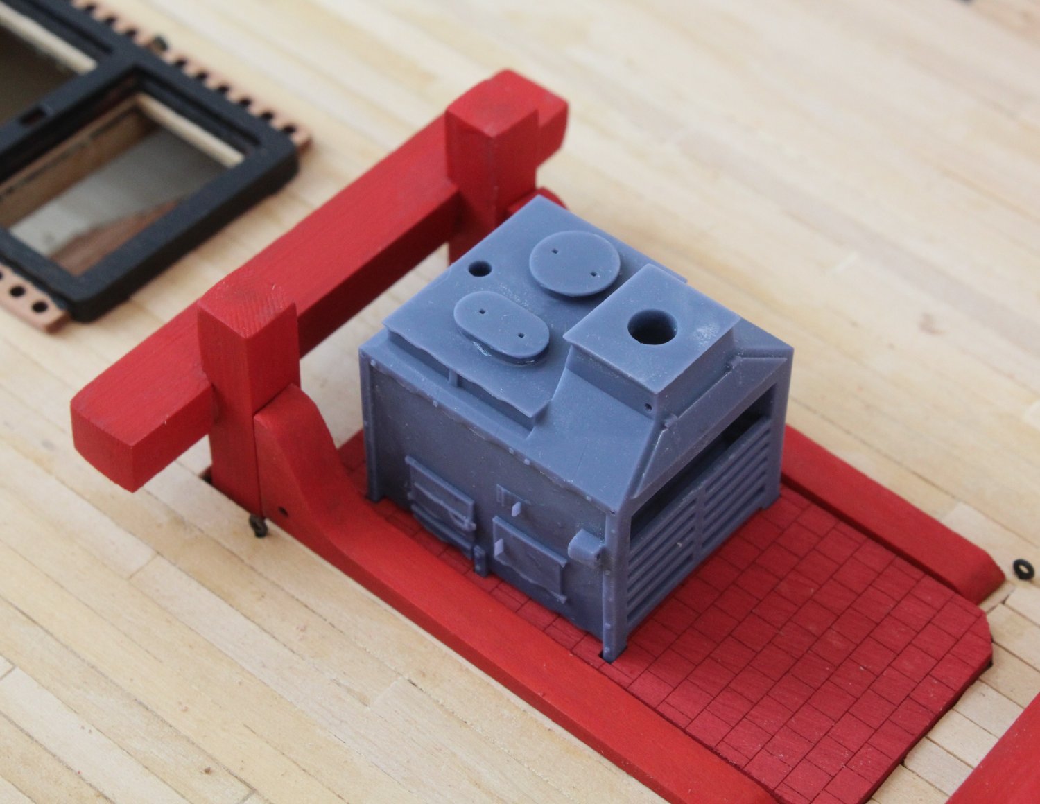
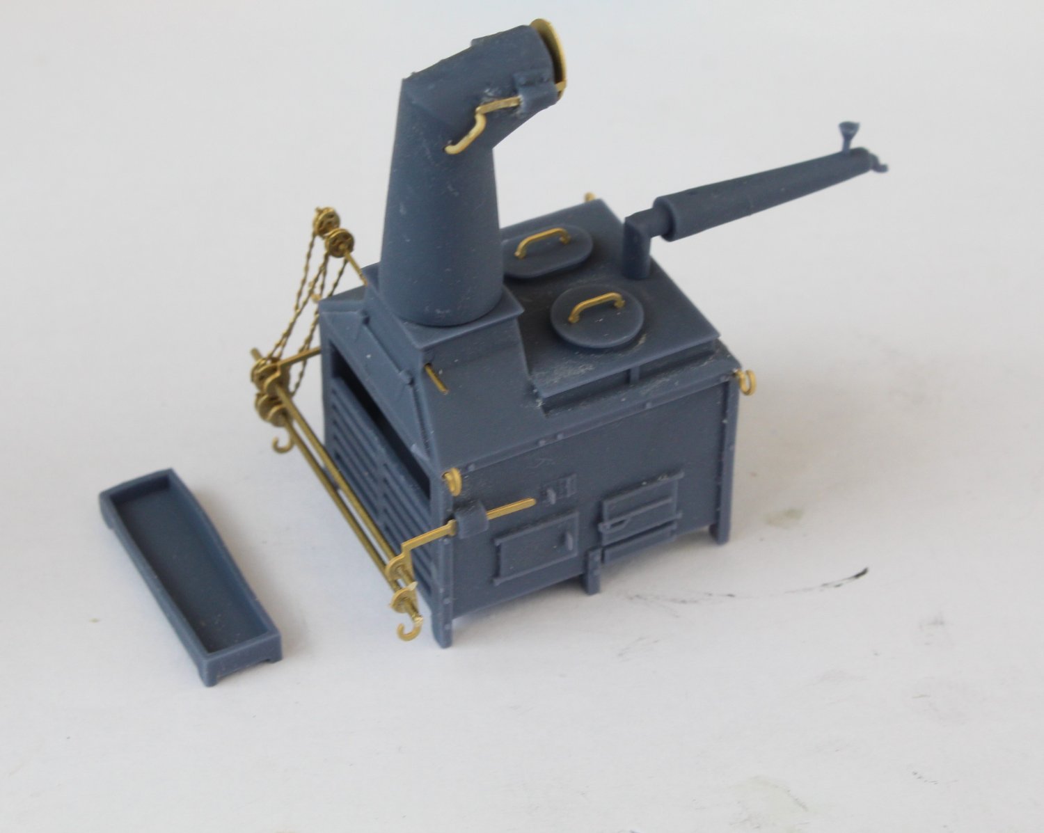
Moving on to the stove the basic stove body was dry fitted to the stove floor.
Next the various PE parts, after cleaning, were added to the stove. I did make a right mess of adding the two chains.
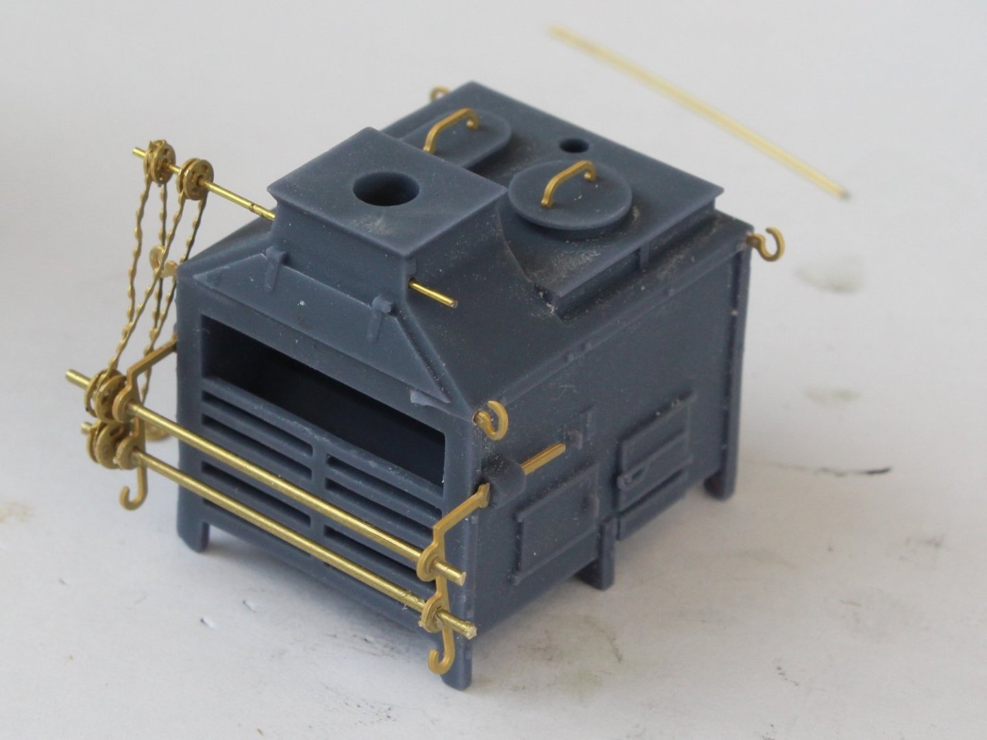
The other parts of the stove were then added.
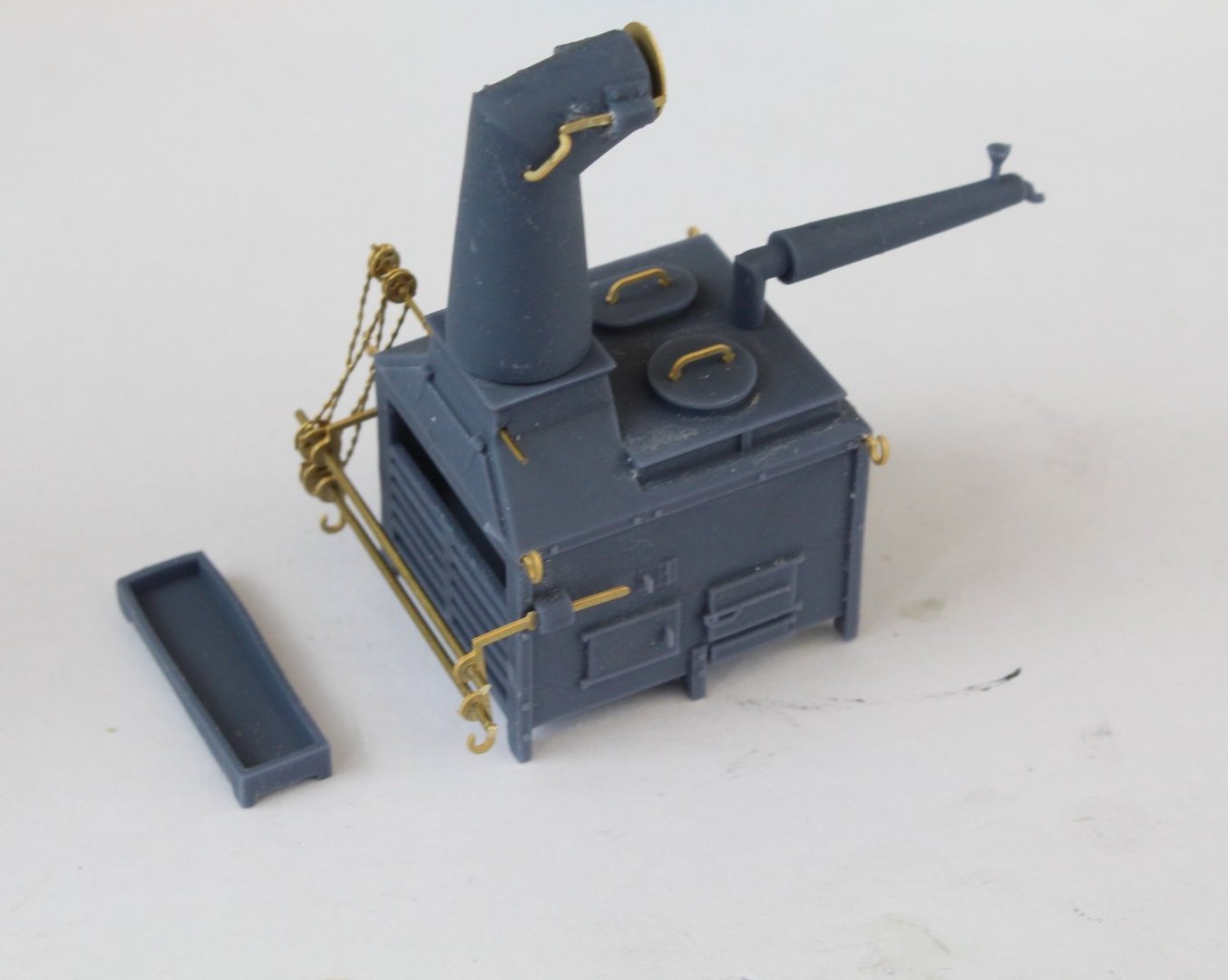
A quick dry fit of the assembly of the hull prior to the painting of the stove.

- KentM, chris watton, mtaylor and 3 others
-
6
-
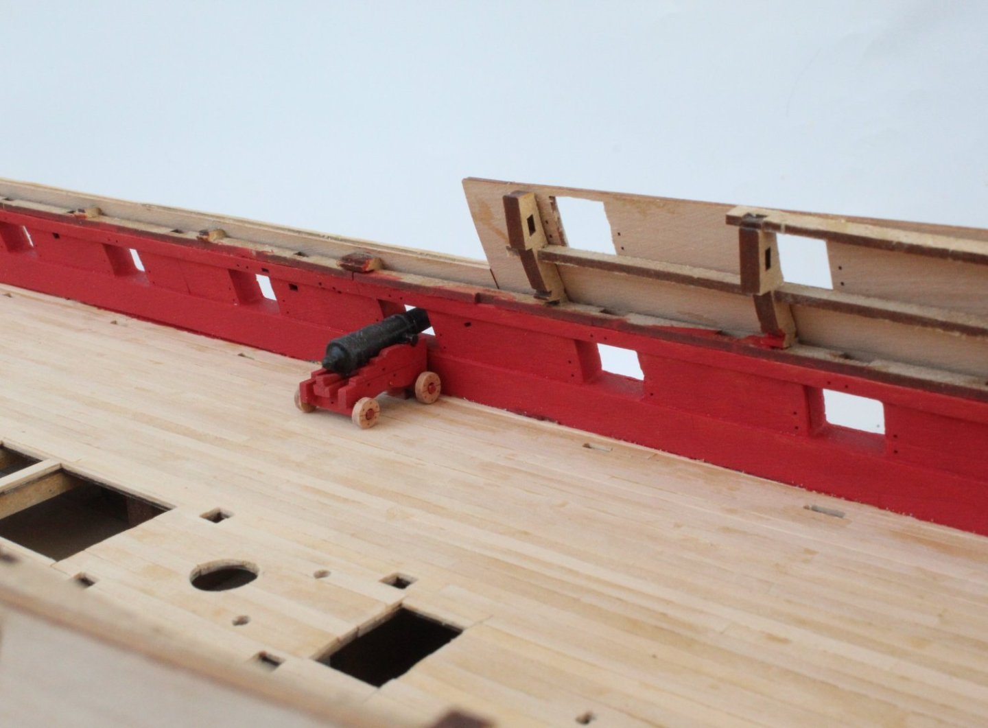
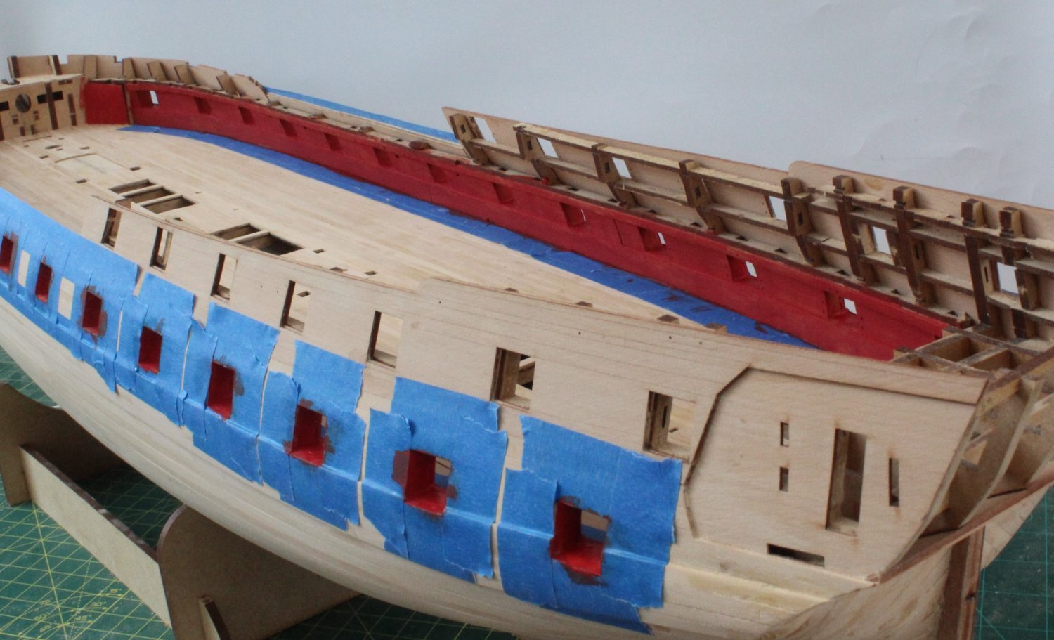
Looking good I see you've opted to cover the slots for the cannon tabs. I assume you are planning to trim the cannon front axle to remove the locating tab.
- mtaylor and Blue Ensign
-
1
-
1
-
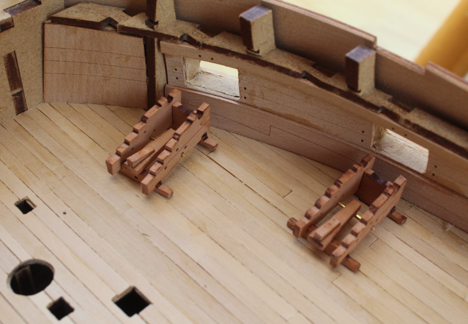
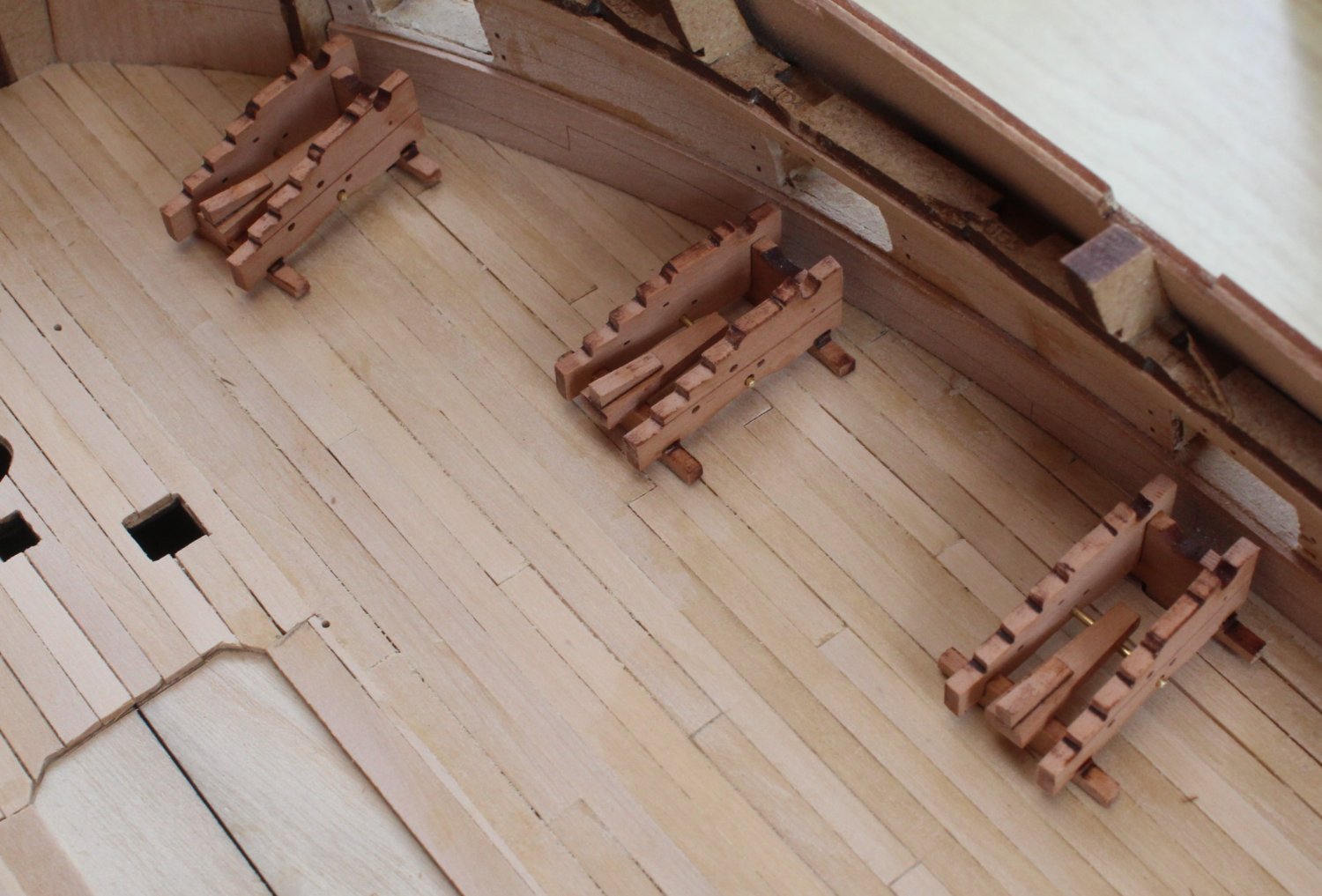
Gun Deck Items
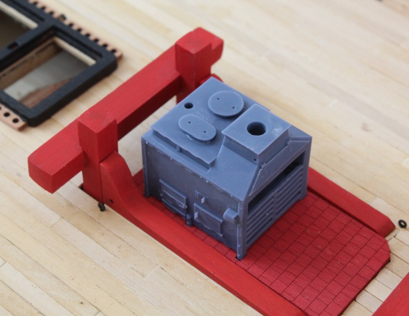
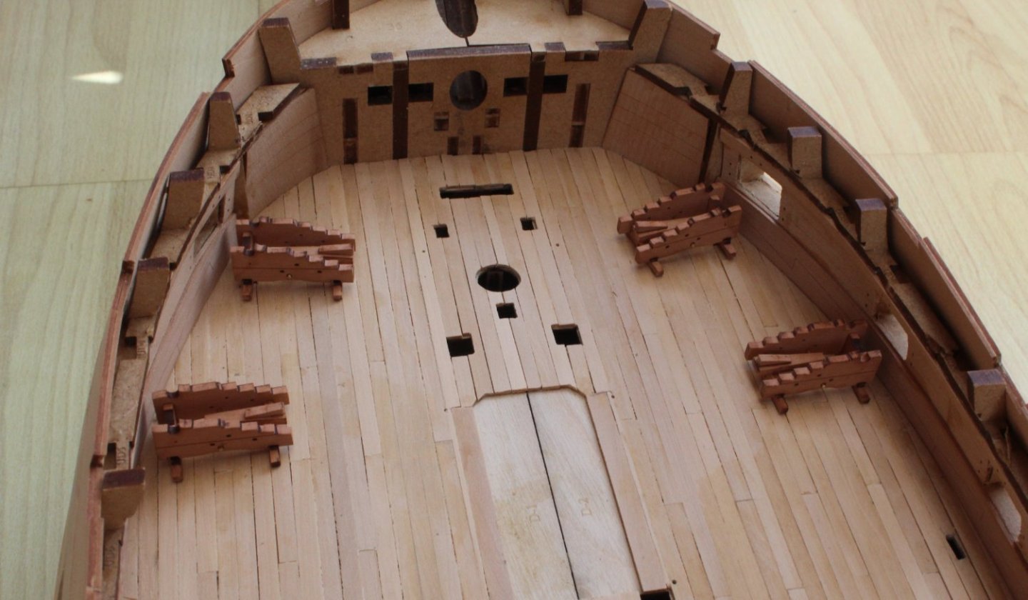
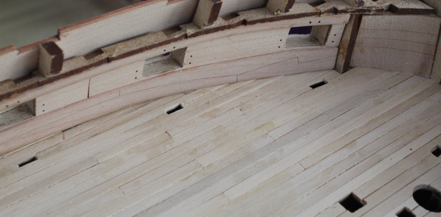
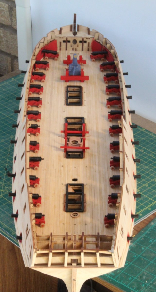
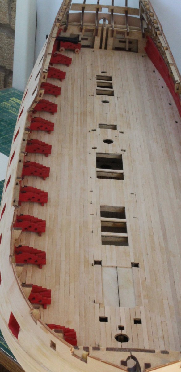
I was able to grab a couple of hours in the shipyard this morning. First task was to paint the various gun deck items. Flat red for the bitts, brick red for the stove base and dull black for the hatches. It was then a case of dry fitting the items to check everything looked good.
The first set of photos just shows the bitts and stove base
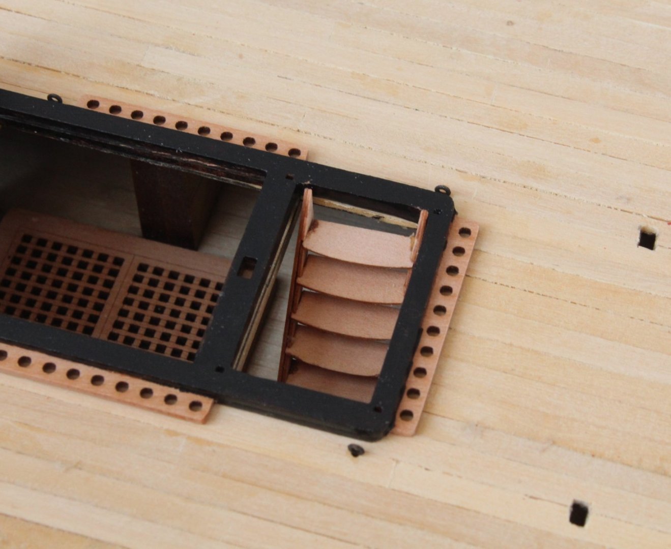
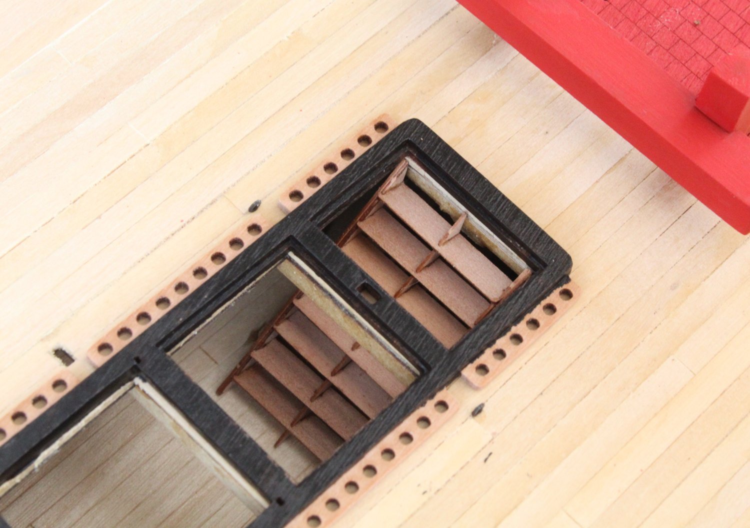
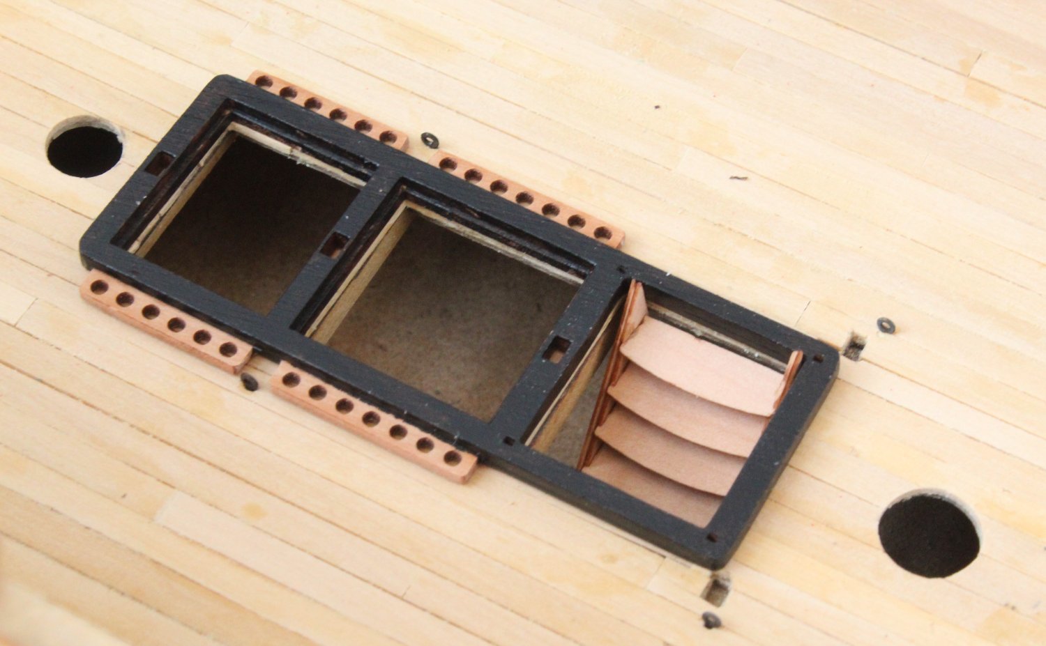
And now a set of photos with all the hatches dry fitted.

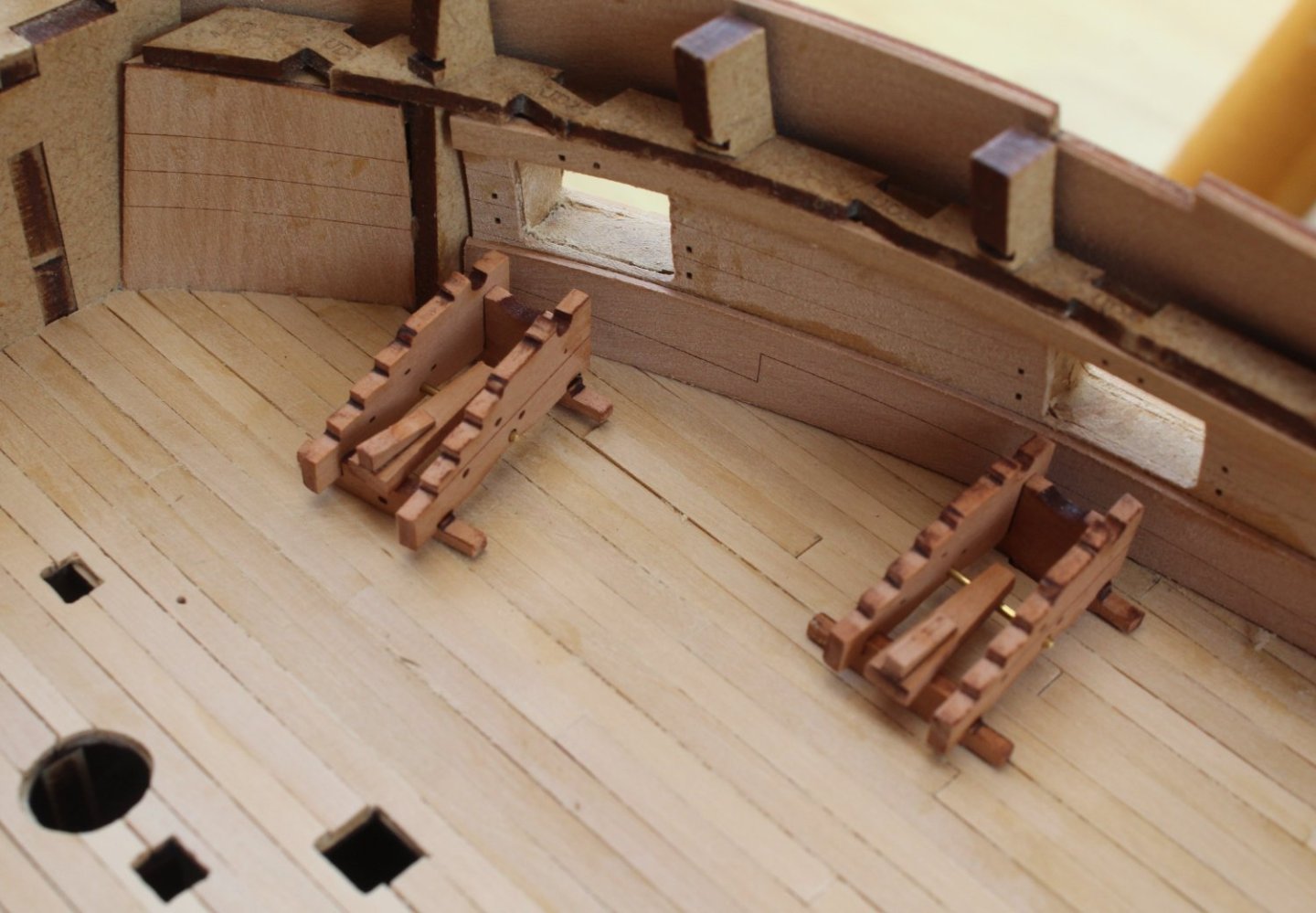
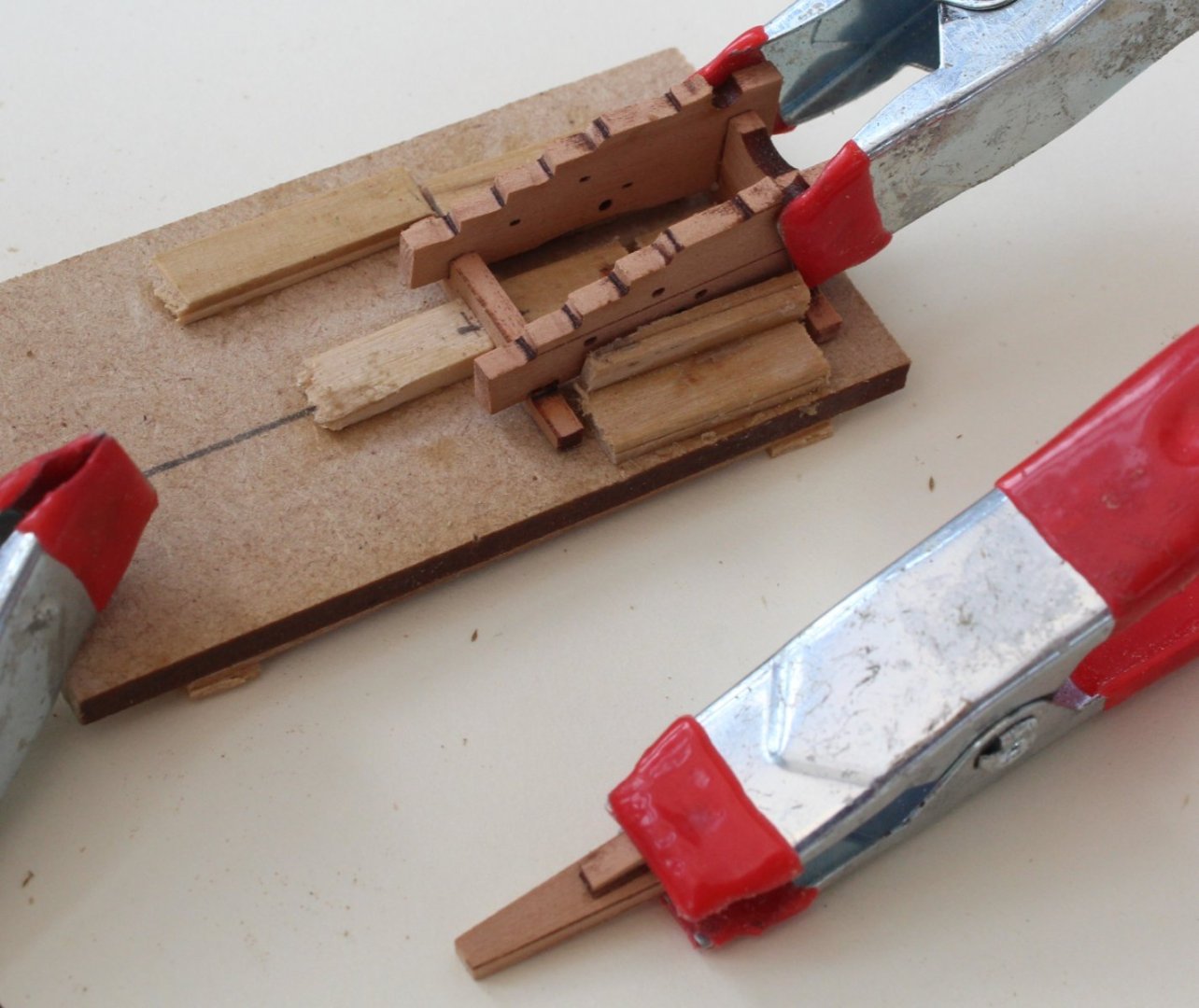
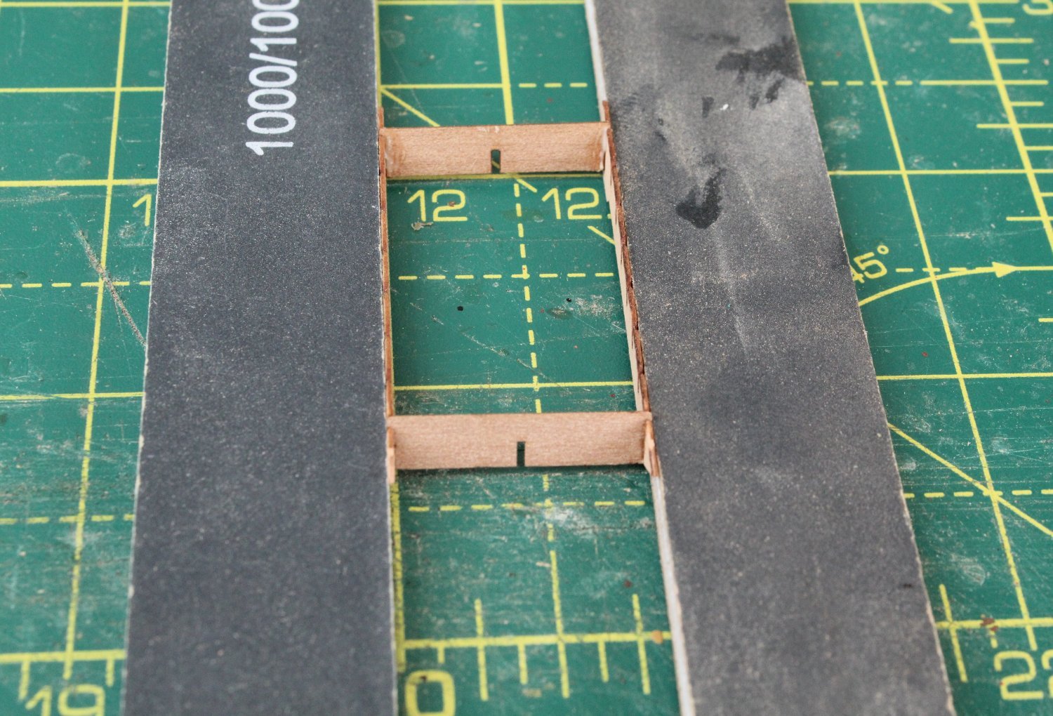
Next I moved on to building the 3 sets of ladders. I like to start with adding the top and bottom rungs and then leave time for the glue to cure before adding the remaining rungs. As can be seen I ensure the assembly is held square as the glue cures.

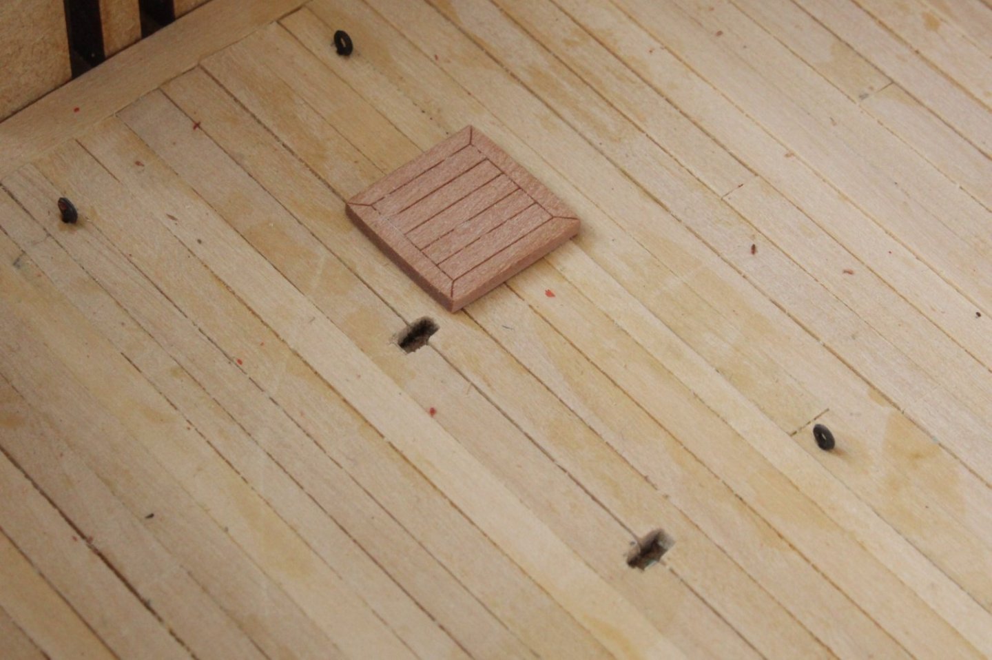
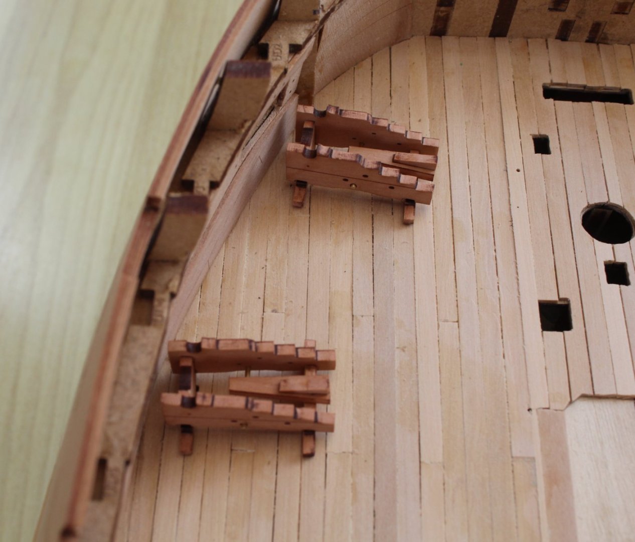
The ladders are now dry fitted, as shown in the next set of photos.


To complete this post I have included a photo of the gun deck with the completed items added. As noted in a previous post all the 24lb cannons have been built and test fitted.

Time to study the manual and plans before moving on to the next task in hand.
-
Starting To Add Gundeck Items
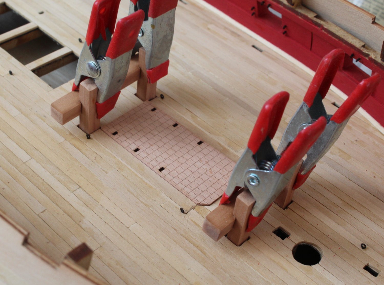
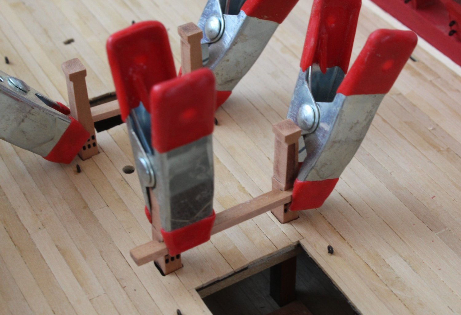
I was able to sneak a couple of hours in the shipyard today during our youngest grandson nap time. The first task I undertook was to remove the laser char from the various bitt parts. Once that was complete the bitt supports were placed in position on the gun deck but were not glued. The stove base pattern was also dry fitted. Some pva was added to the joints for the bitt cross beams which were then clamped in place.
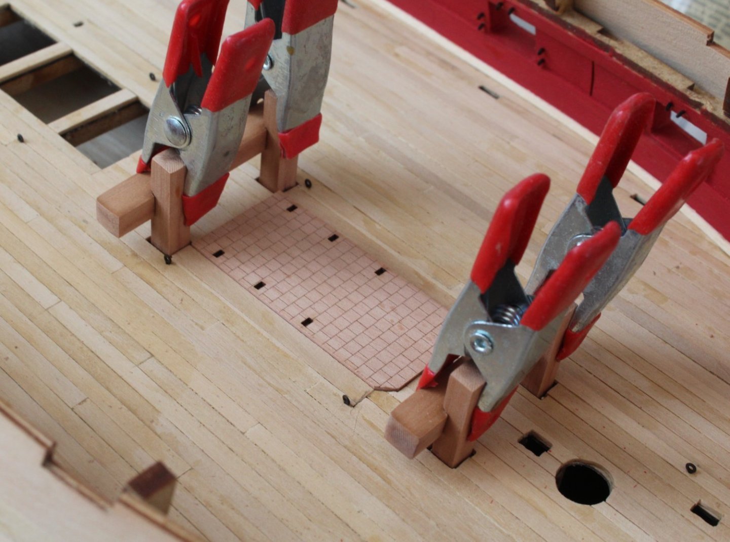

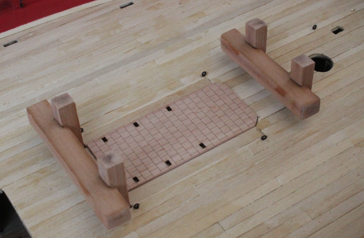
After the glue had cured the clamps were removed and the assemblies were removed from the gun deck. The bitt assemblies were then refitted to check they could be fitted as complete assemblies. The bitt standards were also dry fitted.


Next the cannon ball holders on the various coaming assemblies were taped as they will not be painted black.

The various assemblies were then coated with a WOP and will now be left overnight to dry in readiness for painting. I am hoping I can sneak some time in the shipyard tomorrow after the weekly grocery shopping trip and before the arrival of our two eldest grandsons (10 and 12) after lunch.
- Morten, chris watton and KentM
-
3
-
13 minutes ago, Thukydides said:
You could try filling the gap with milliput or greenstuff. You would need to paint the cannon after doing so, but looking at that gap it shouldn't be hard to fix with a bit of putty.
@chris watton is sending me a replacement which is greatly appreciated.
- Ronald-V, allanyed, Ryland Craze and 3 others
-
6
-
A quick update
My time in the shipyard will be limited over the next few days due to more grandparent duties, but I'm sure I will be able to sneak the old hour or two.
I had a couple of things to finish before I could start work on adding the gundeck items.
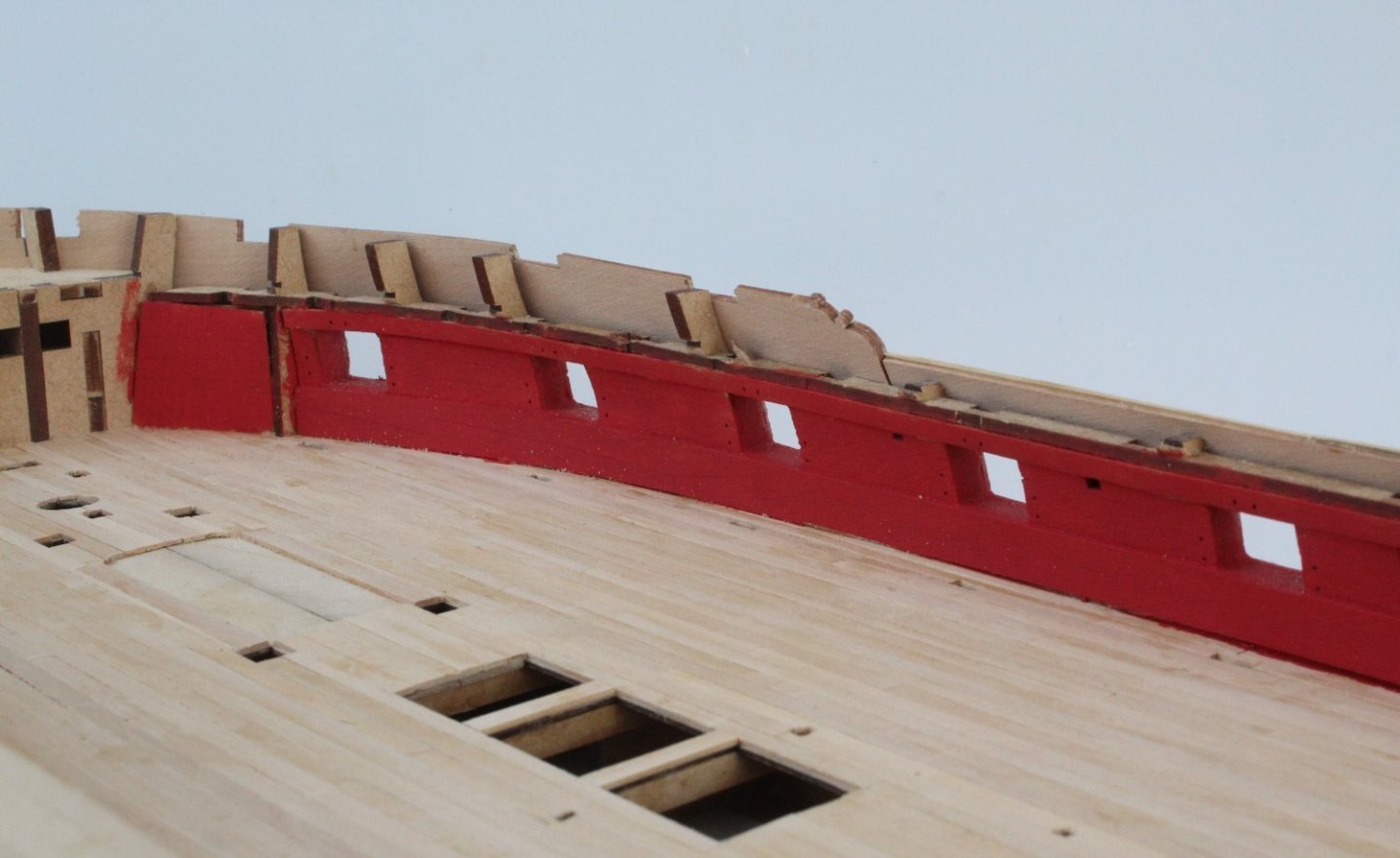
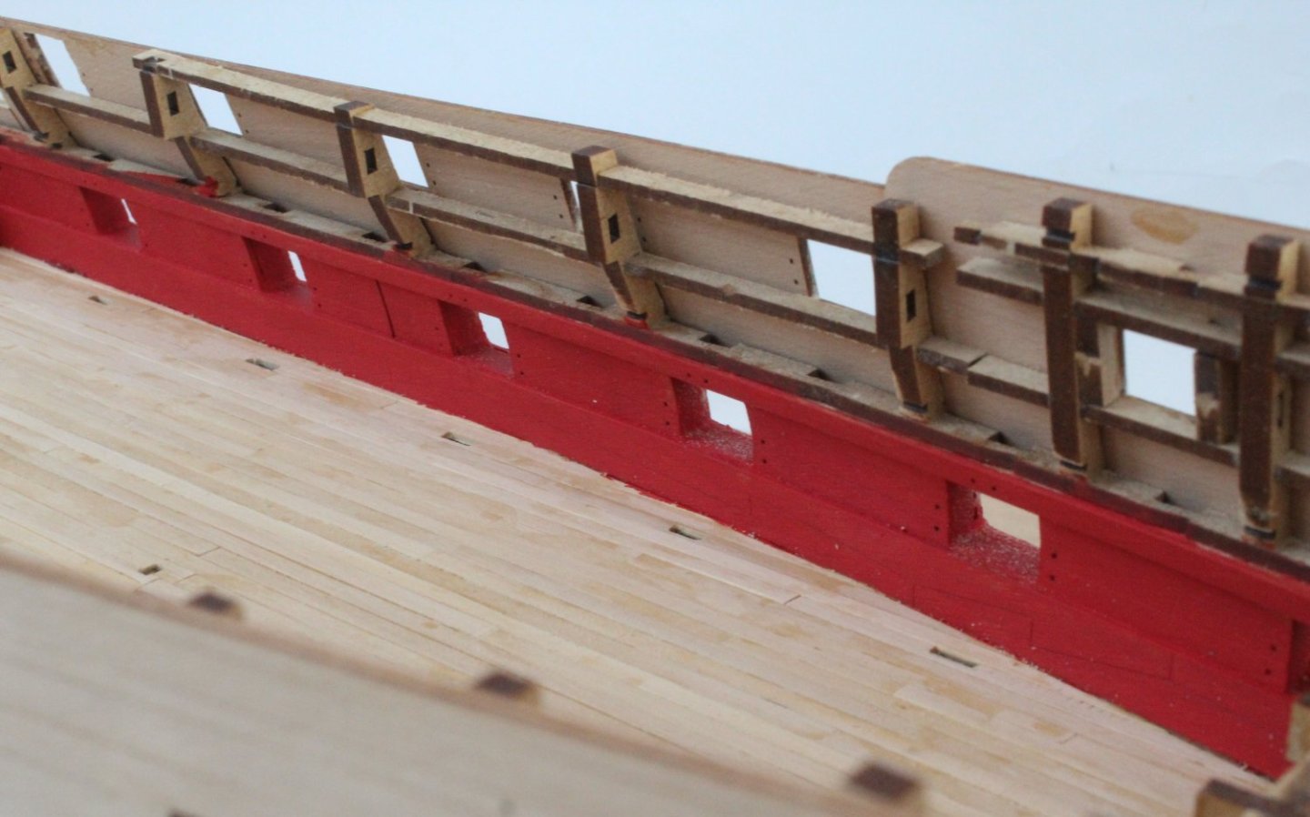
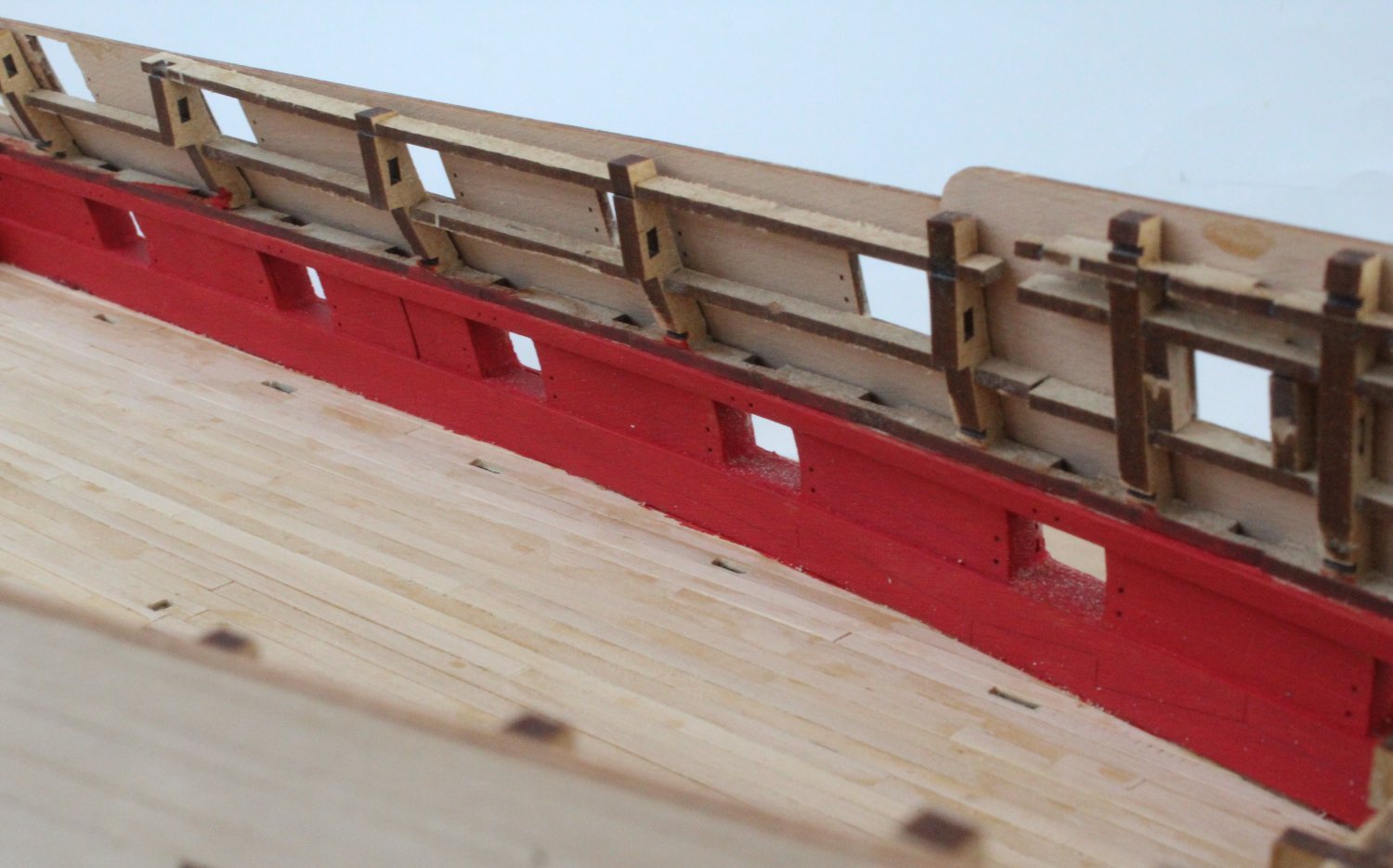
The first task was to paint the bulwark and upper ledge cleats flat red.
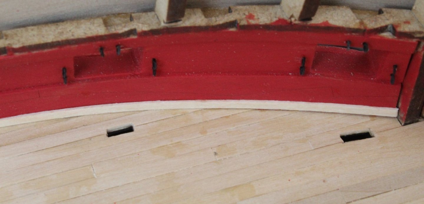
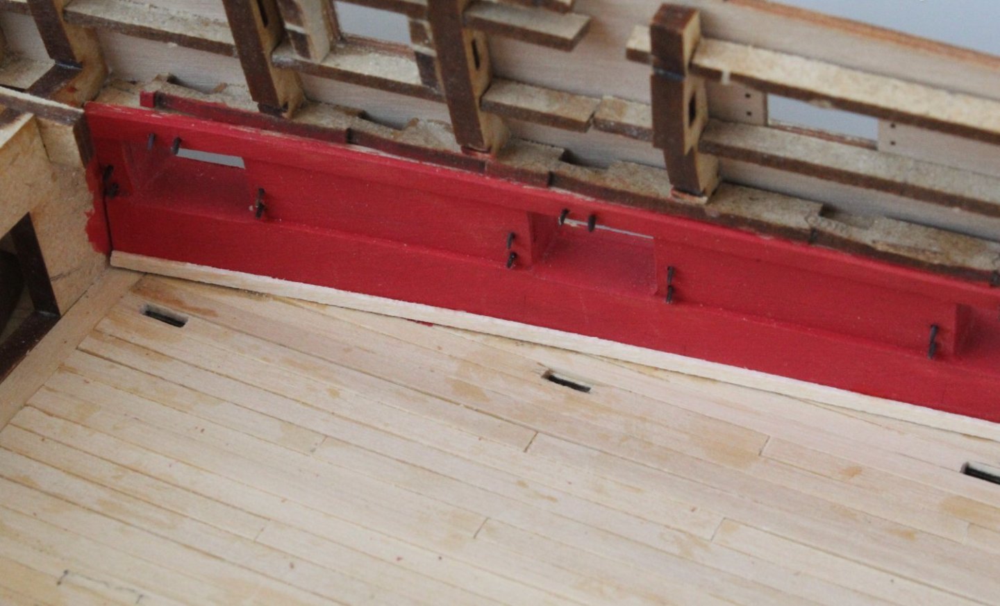
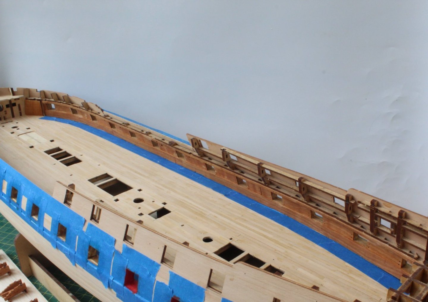
As mentioned in previous posts I was thinking of adding a waterway. According to Longridge:
"The 'waterways' for instance, are strong lengths of timber set in the angle between the deck and the side of the ship. They varied in size and shape quite considerably; the last thing they resembled was any sort of gutter to carry away water. The inner edge was generally chamfered off to allow the front "trucks" (wheels) of the guns to butt against it."
Anyway this is what I have done so far. As yet I have not added scuppers to the waterways. e.g. holes where the water drained out.

- KentM, Ryland Craze, mtaylor and 3 others
-
6
-
24 minutes ago, Mike_H said:
And more than 2 year's later, more thanks and congratulations on your build and your log. Just as you built Alert waiting for Sphinx, I had planned one of Vanguard's fishing boats while waiting for Surprise. Surprise is delayed so I will use Alert to fill a slightly longer gap and since I only model build when the weather keeps me indoors, she should do the trick. Your log will act as a running commentary on what to be thinking about at each stage, and your build as a beacon of success. So thanks - and I expect you will hear from me (keeping it all within Yorkshire)
Mike
Enjoy the build. I like to detail the processes I use when posting on my build logs. Currently build Indy. I will be happy to assist you where I can.
- AJohnson and Ryland Craze
-
2
-
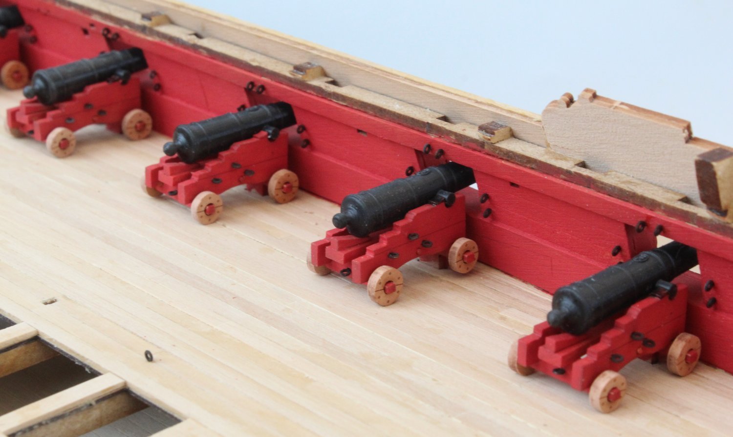
26 x 24lb cannons for Gun Deck
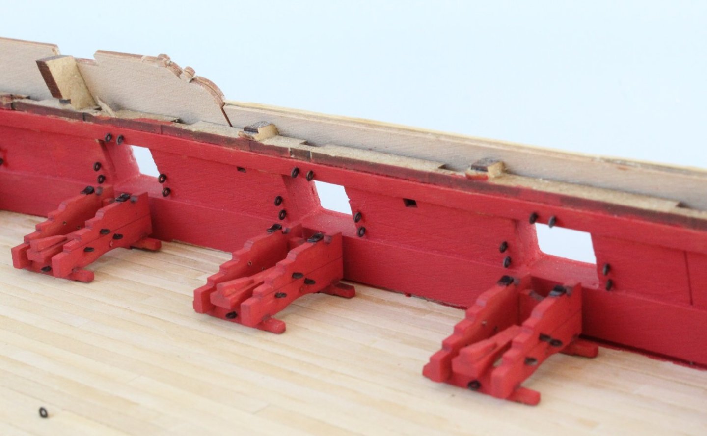
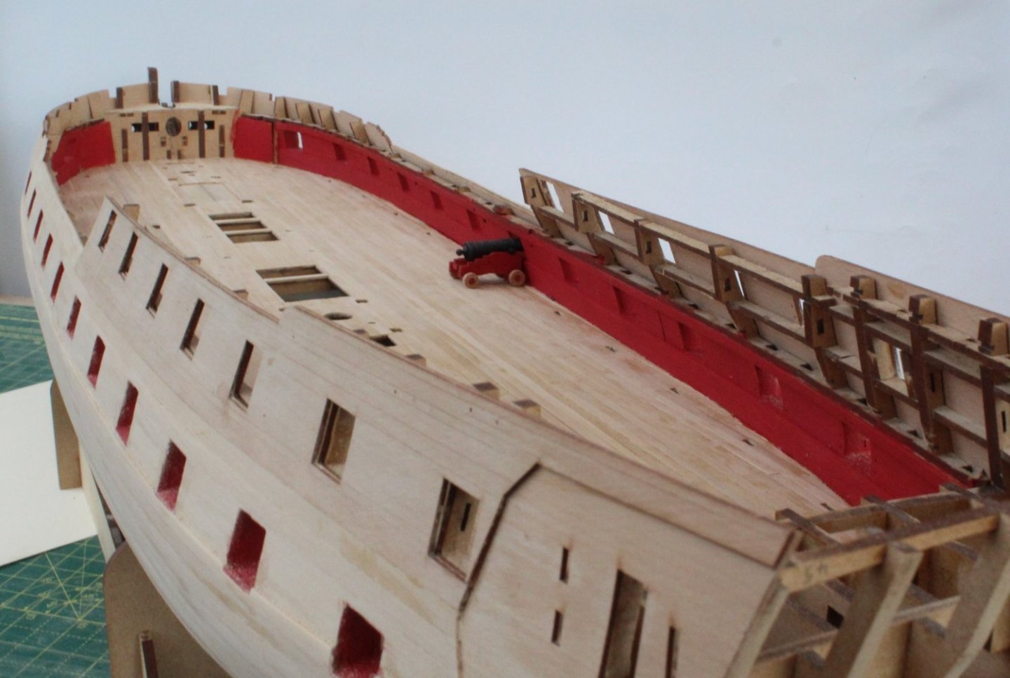
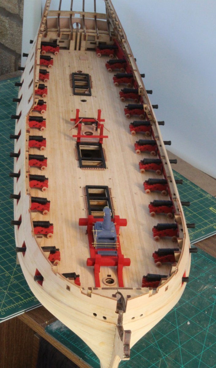
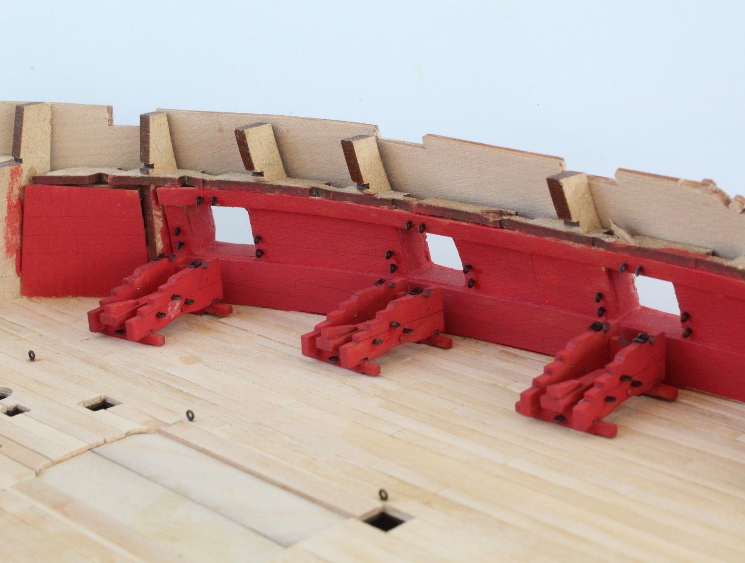
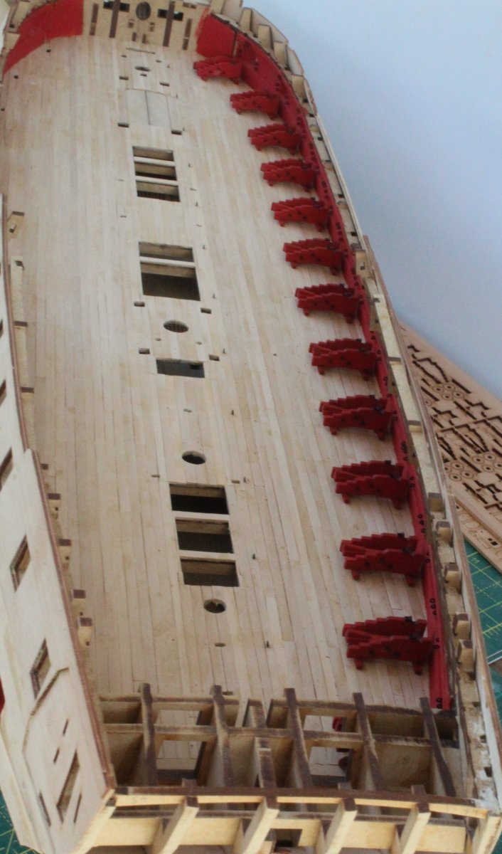
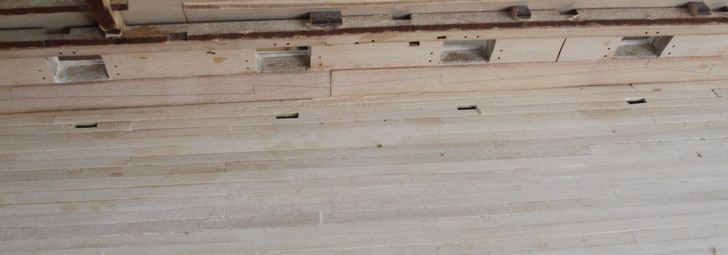
I have now completed the task of drilling and adding the 364 eyebolts to the gun deck, gun ports and cannon carriages. I have also removed the laser char from the outer edges and fitted 104 wheels to the 26 cannon carriages, 4 wheels per carriage (2 small and 2 large). It has been a consuming and, at times, monotonous activity but I am really pleased with the end result so it was time well spent. In the ensuing photo's the cannons are only dry fitted to the carriages and the carriages are only dry fitted to the gun deck.
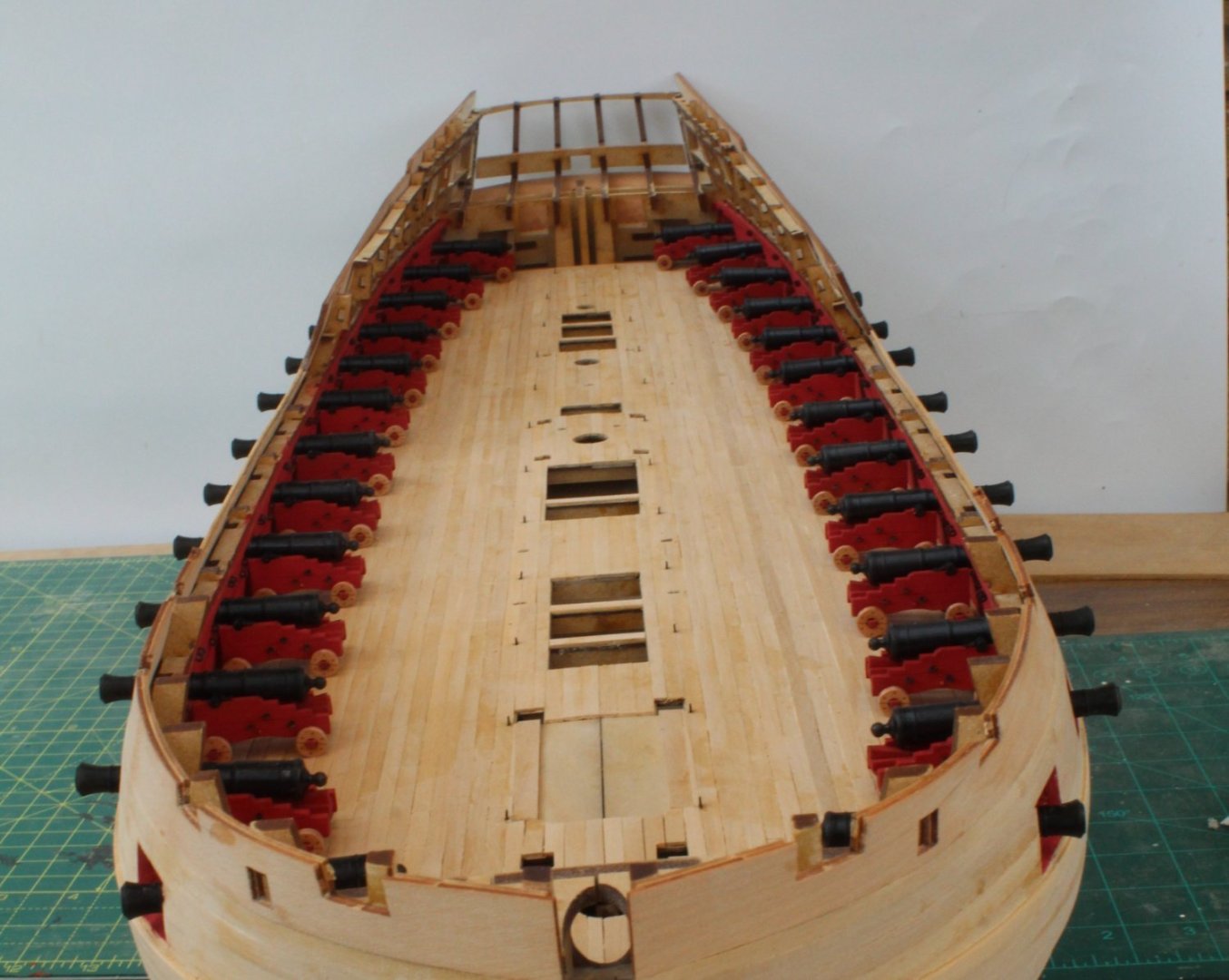
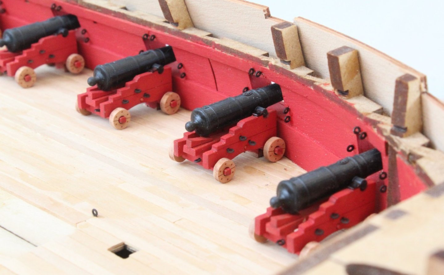

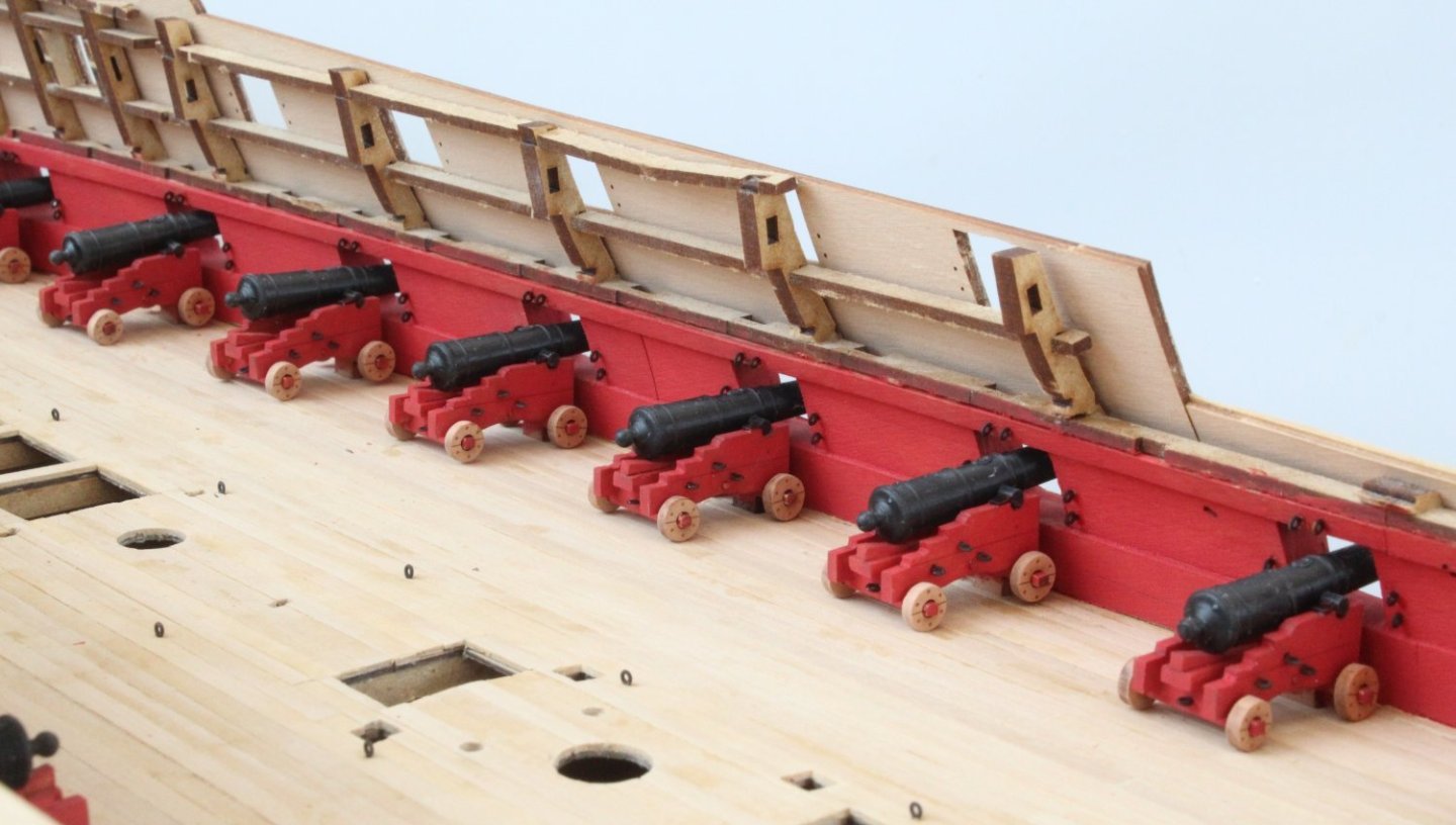
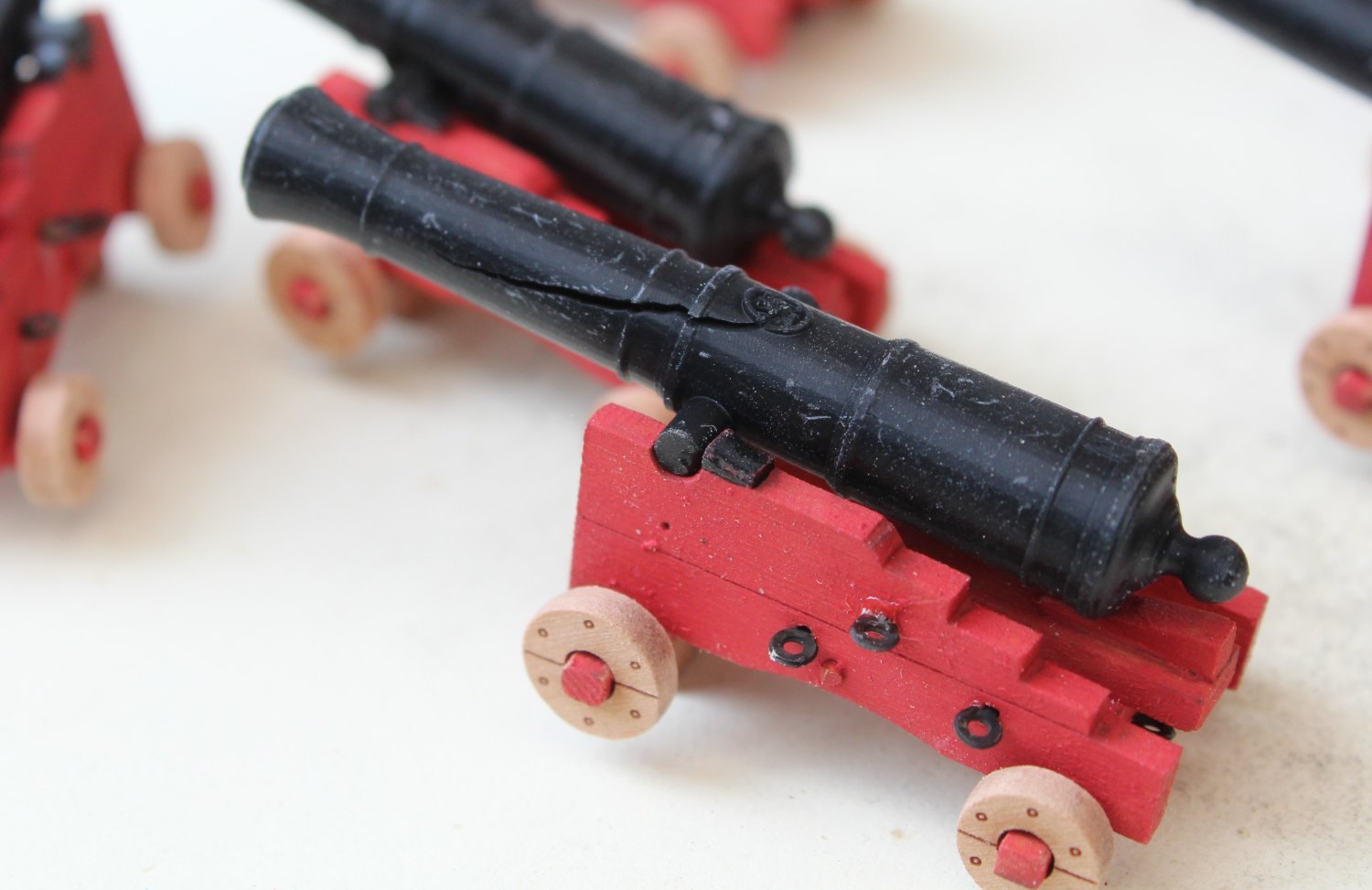
There does seem to be a manufacturing flaw with one of the cannons, so I will have to make sure it is placed in a position so the flaw is not that evident.

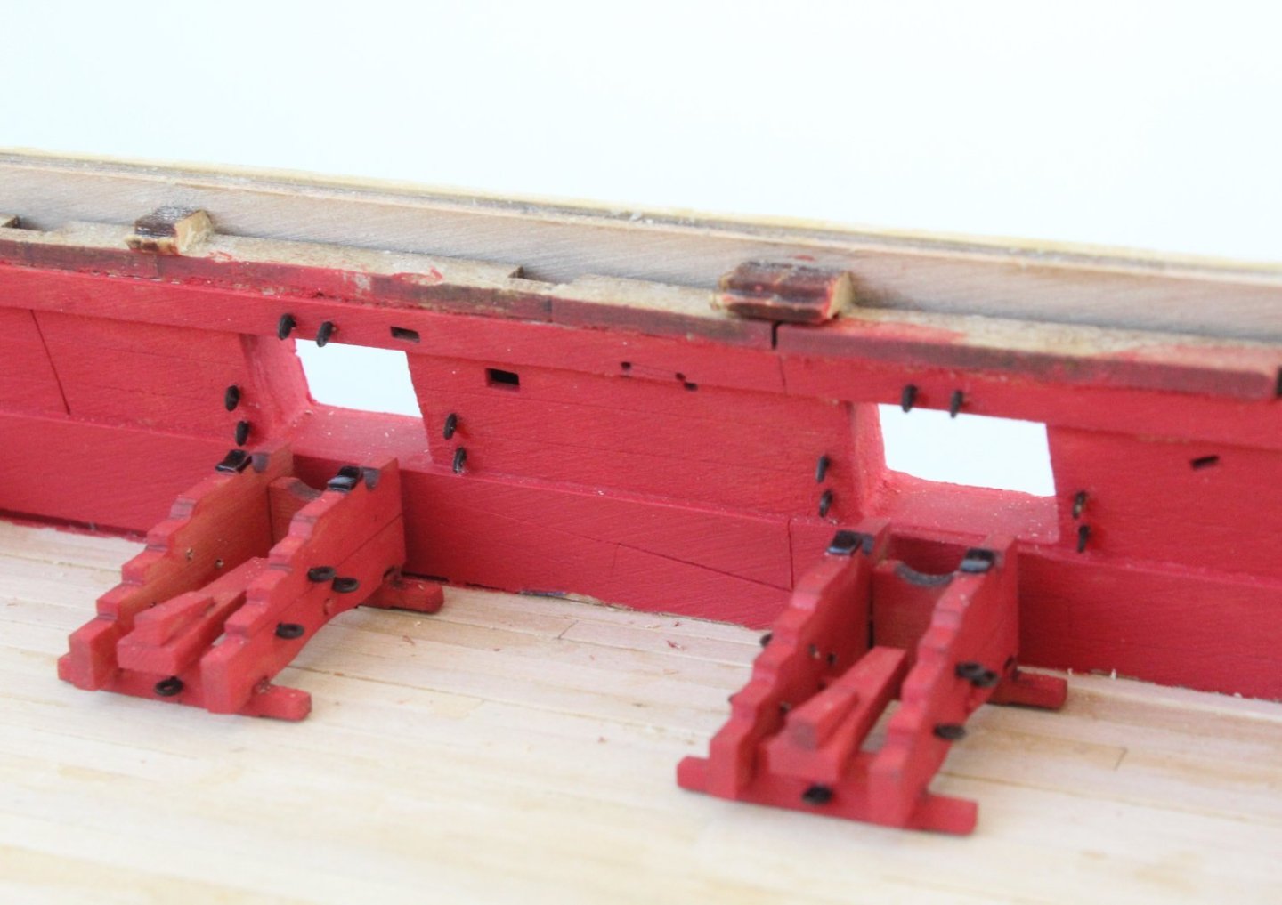
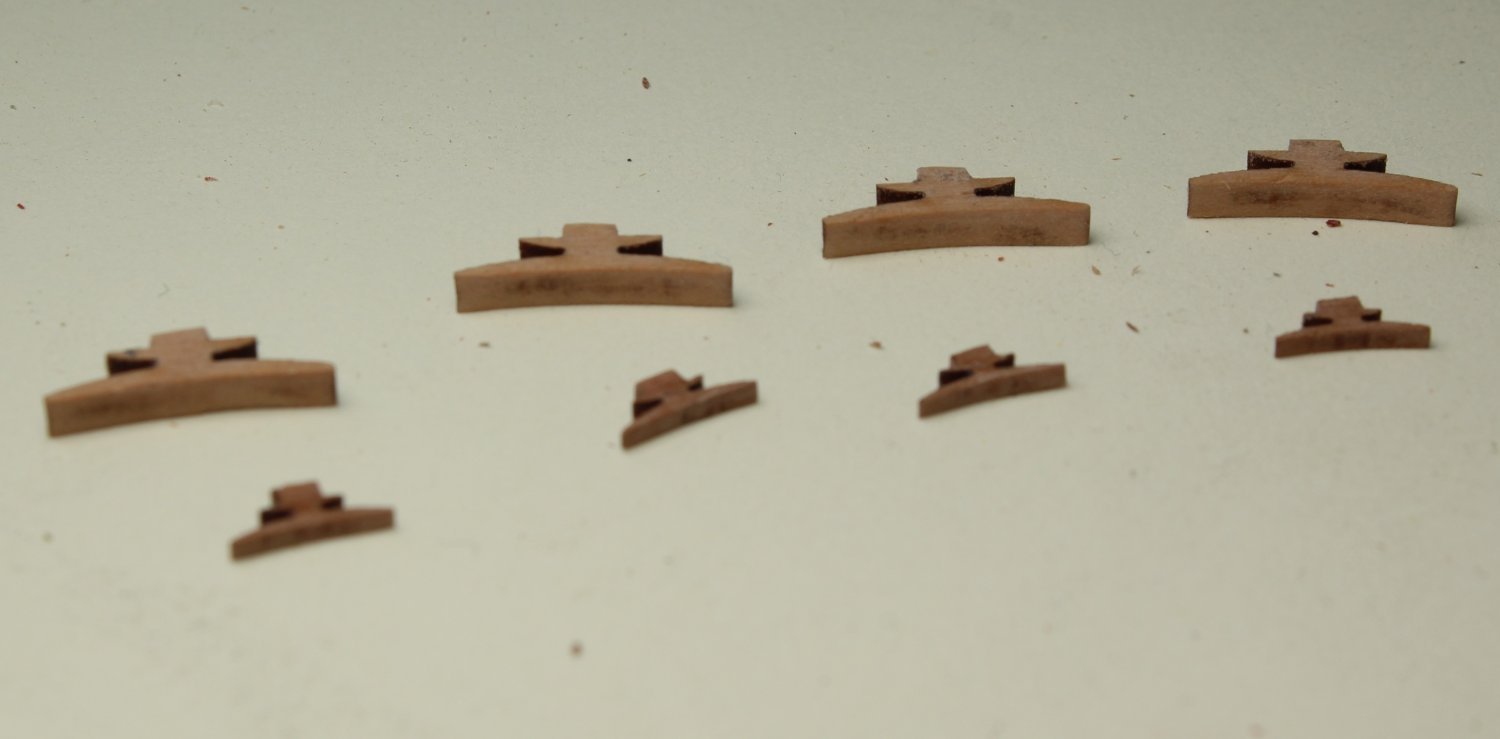
The next task was to fit the cleats to the inner bulwarks and upper ledges. The laser char was removed from the cleats, as can be seen in the next photo. Although I have only shown 4 off of the smaller cleats there are actually 6 off to fit.
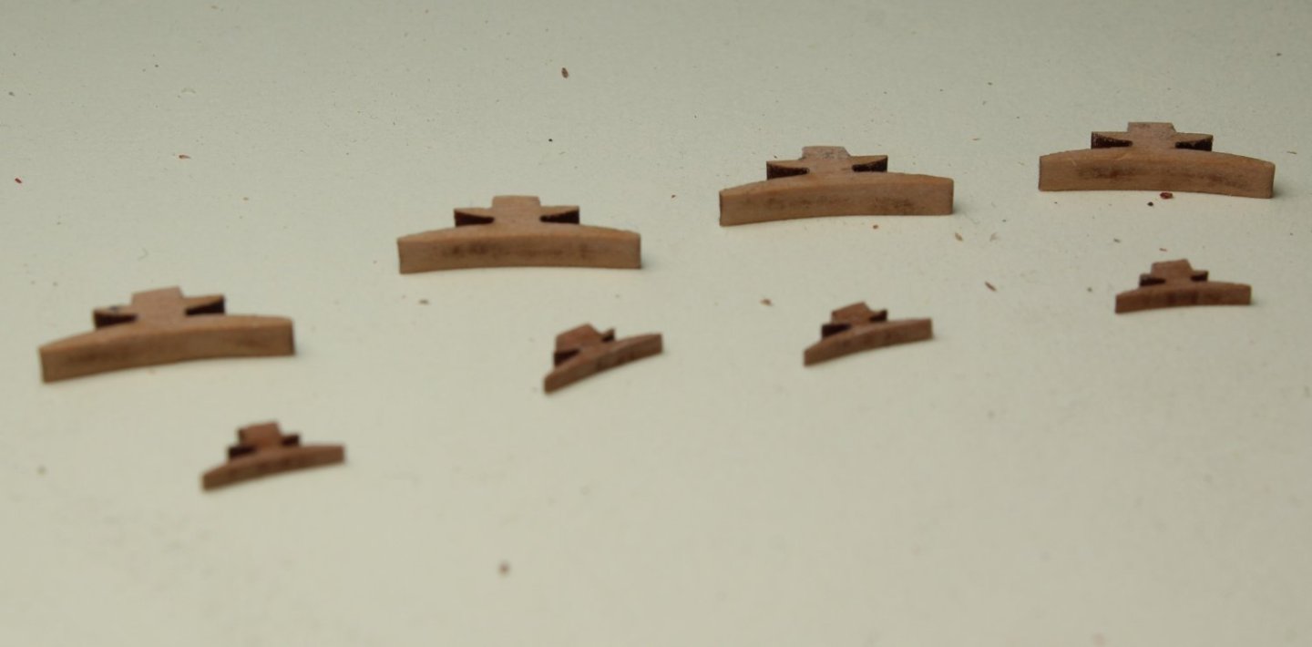
The cleat end tabs were coated with pva and were a nice fit when placed the locating slots provided. They just need to be painted with a coat or two of flat red paint to complete the task.
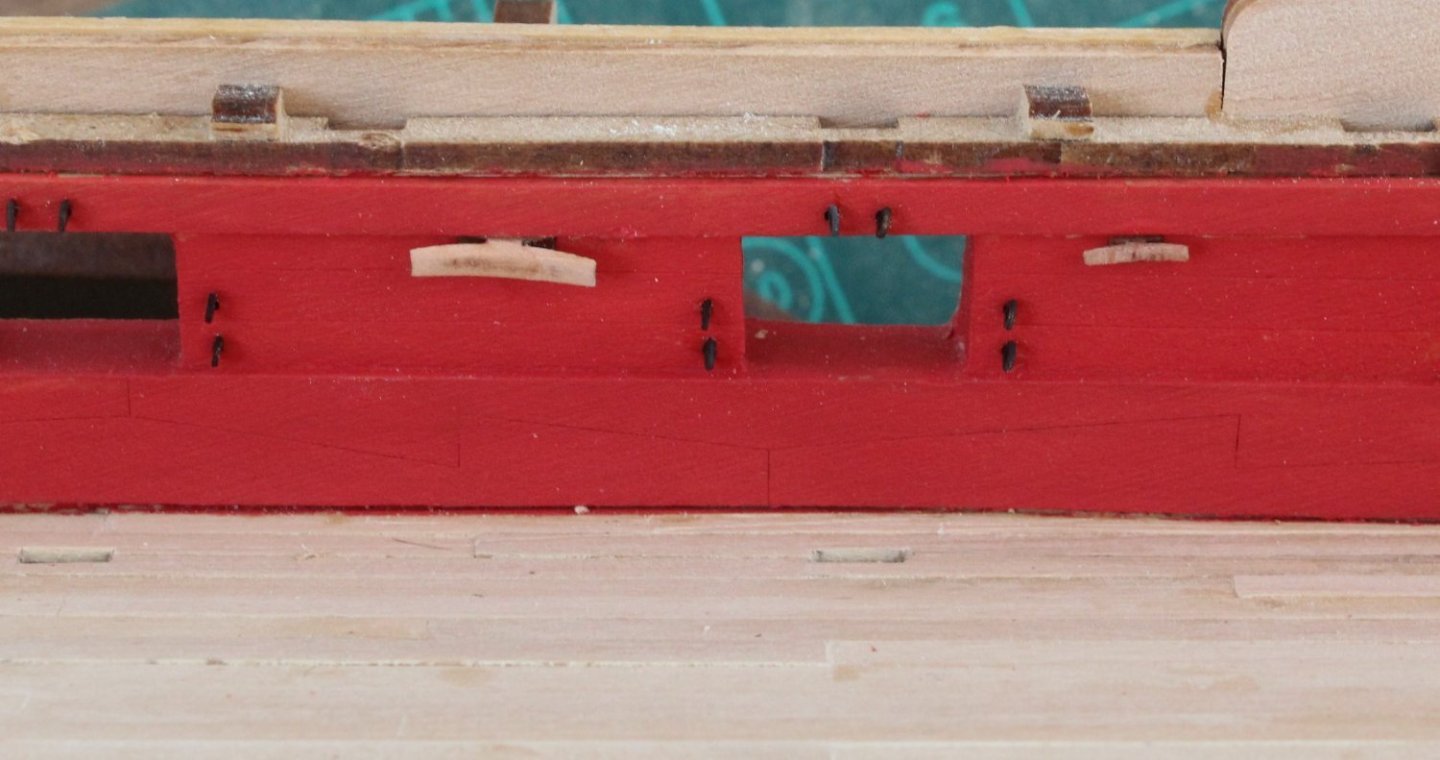
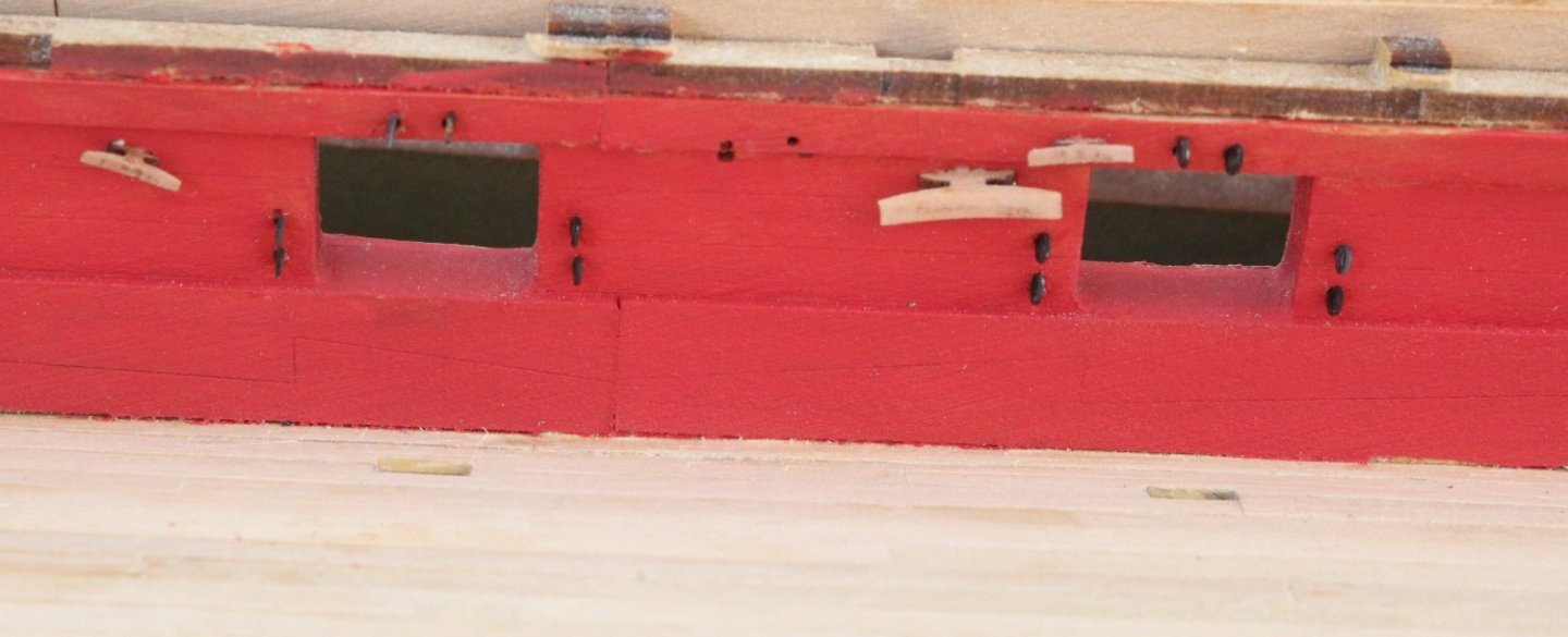
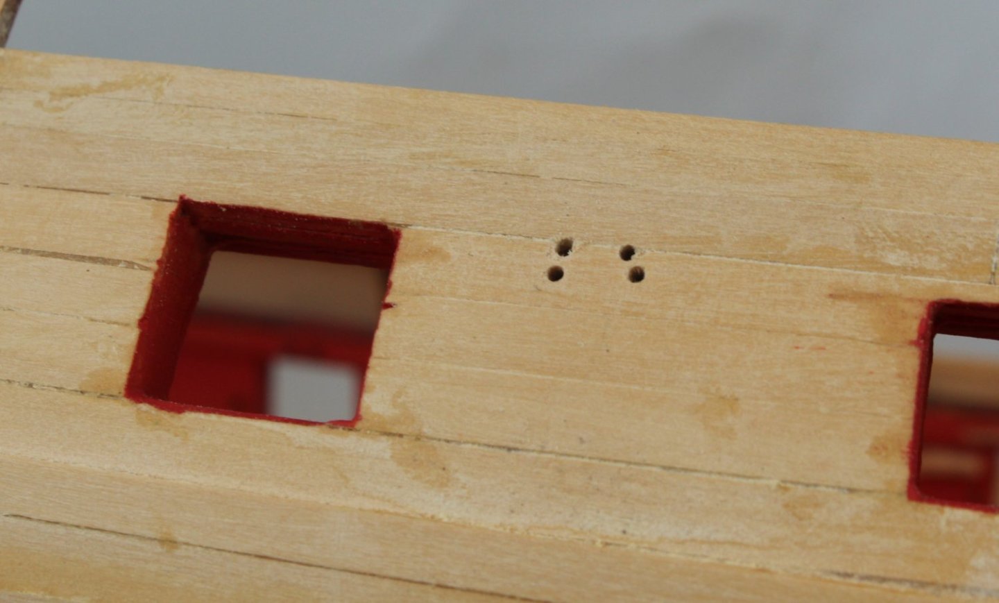
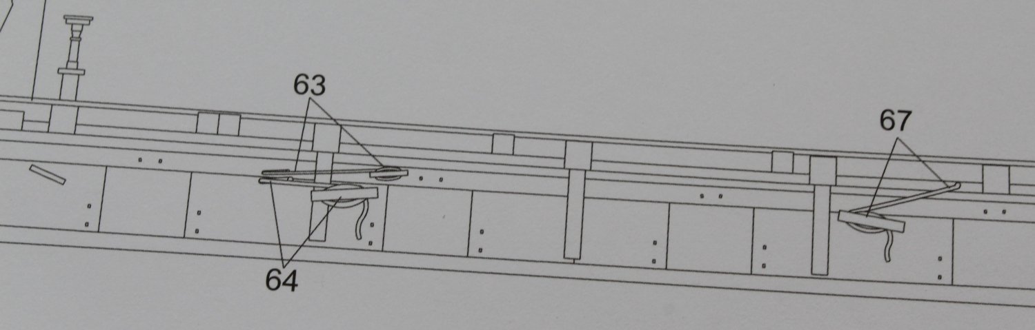
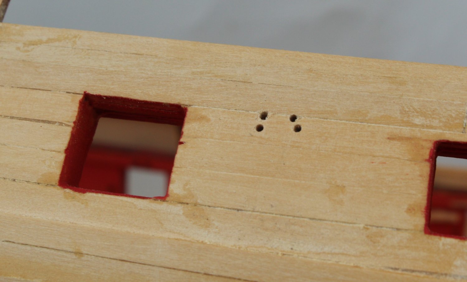
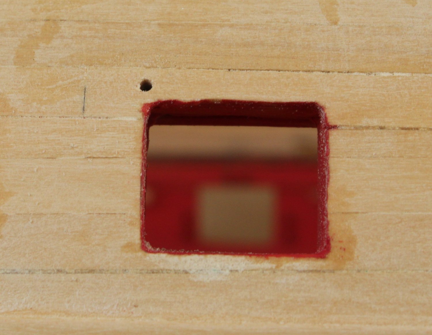
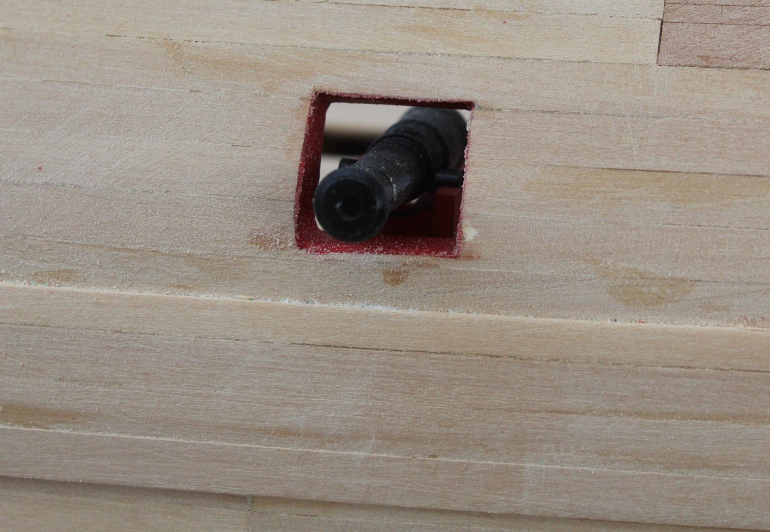
There are some holes required to be drilled through to the outside from the bulwarks and upper ledges for the rigging. With reference to the relevant rigging sheet the holes to be drilled were soon identified.
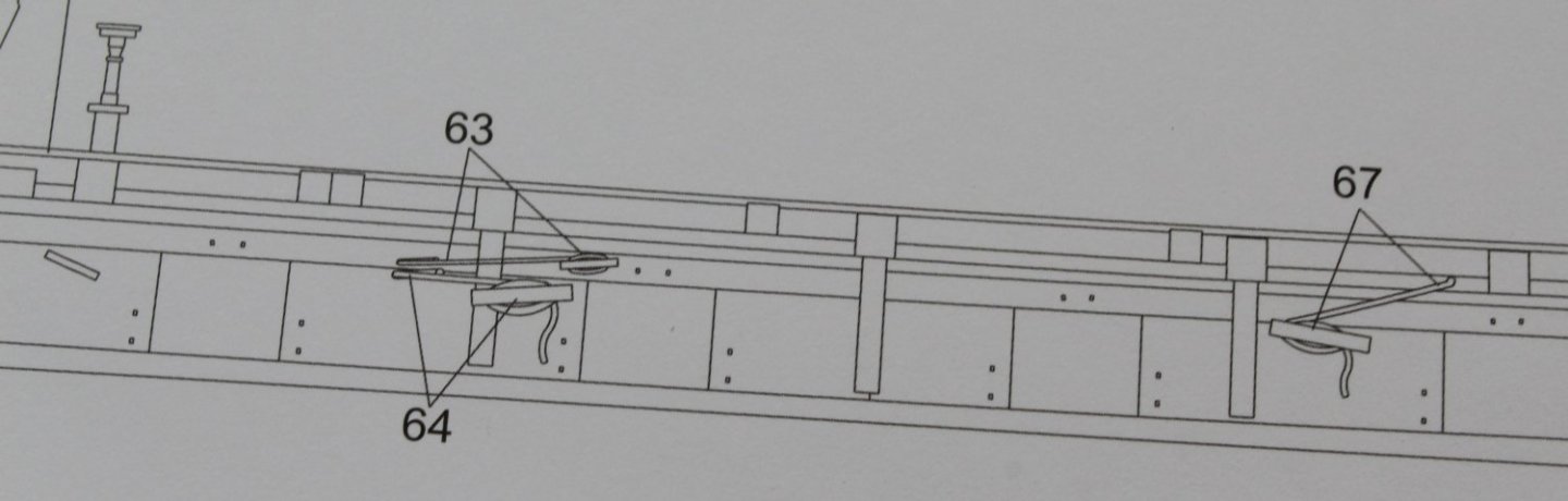
A 1mm micro drill bit was used for this task. Although the rigging is only fed through the aft two holes for threads 63 and 64 I have drilled all 4 holes provided on the bulwarks and upper ledge patterns.
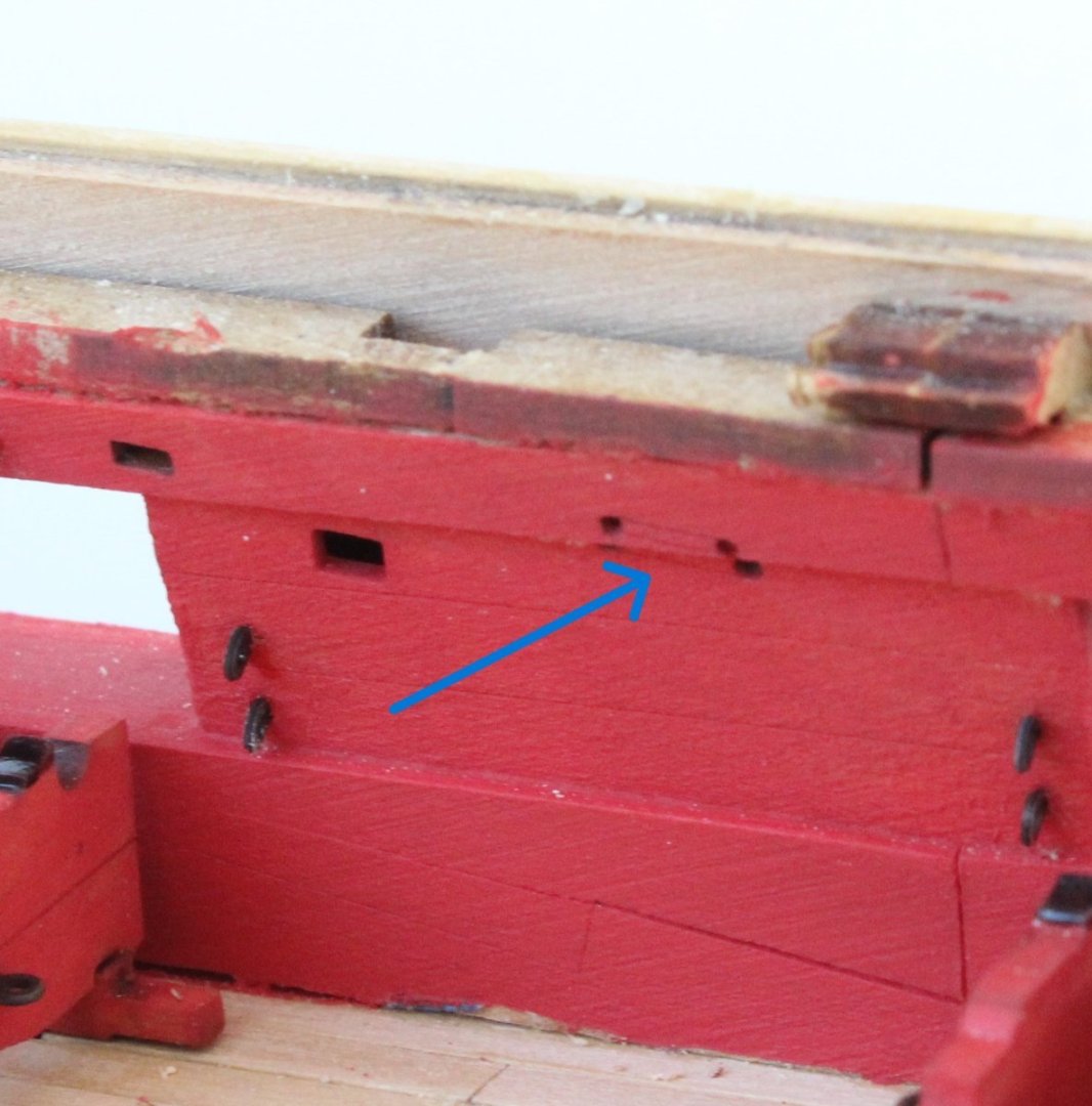
The hole for rigging item 67 is shown in the photo below.

This represents the completion of a major milestone for me. I can now move on to the task of adding the various items to the gun deck.
-
1 hour ago, allanyed said:
Nicely done Glenn!!!!
I don't recall if this came up previously, but for your carriage axles, if not for this build, maybe for the future, have you seen post #129 of https://modelshipworld.com/topic/29563-hm-brig-sloop-flirt-1782-by-glbarlow-vanguard-models/page/5/#comment-858504 to easily make round axles rather than square with radiused corners? Then again if the trucks are precut with their center holes, the fit might not work.
Allan
Hello Allan
I usually round the axles, but it has not been necessary for the Indy as the wheels are a good push fit.
- mtaylor, allanyed, Knocklouder and 1 other
-
4
-
Adding Eyebolts for 24lb Cannons Carriages and Gun Port Openings
Not the most exciting day in the shipyard as it was a highly repetitive task of adding 14 eyebolts per cannon. Thankfully I have managed to complete adding the eyebolts to all the starboard side cannons and gun ports. It will be more of the same tomorrow, I can hardly wait. I also have to add all the wheels to the cannon carriages at some point and the most time consuming task will be removing the laser char from the outer wheel edges. I also need to paint and add the various cleats to the inner bulwarks.
I will consult with the rigging plans as there are some 1mm holes on the inner bulwark/upper ledge which need to drilled through to the outside. As can be seen in the photo below there are 4 possible holes so I just need double check which holes are required to be drilled. I am assuming it is just the top pair of holes at the moment. I can see the top holes in the pictures with build instructions 243 and 245 have been drilled.
Here is a few photos of todays progress. The cannon carriages (without wheels) have been placed in position.


I am also considering adding waterways between the deck and spirketting and is something I will look at doing later this week.
- ECK, p.hoek, GrandpaPhil and 7 others
-
10
-
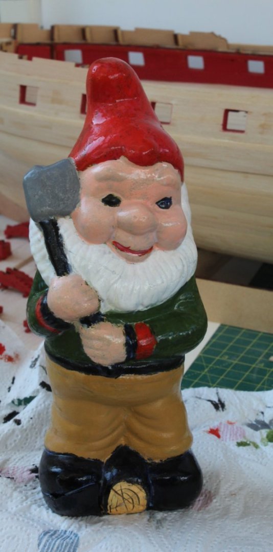
Garden Defender Repair
One of the advantages of the model boat hobby is I have plenty of different glues, paints and varnishes available. Whilst out in the garden with our granddaughter this weekend we noticed one of the garden defenders was is need of some TLC. So the sad looking broken gnome was taken to the shipyard. After a good clean the broken porcelain parts were glued back together. As most of the paint had disappeared a major repaint was required followed by a couple of coats of varnish.
Hi Ho Hi Ho it's off to work he goes.
Only 364 Eyebolts To Fit
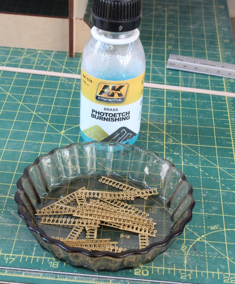
Back to the task in hand this morning and I released the required number of PE-1 eyebolts from the photo etched sheet. Where possible I kept them in strips of 14 which would cover the requirements for one cannon. When this was not possible I opted for 2 x strips of 7. The strips were cleansed in acetone and then put in a sieve which was then placed in a pan of very hot soapy water and left for 20 minutes on a low heat. The strips were then ready to be chemically blackened.

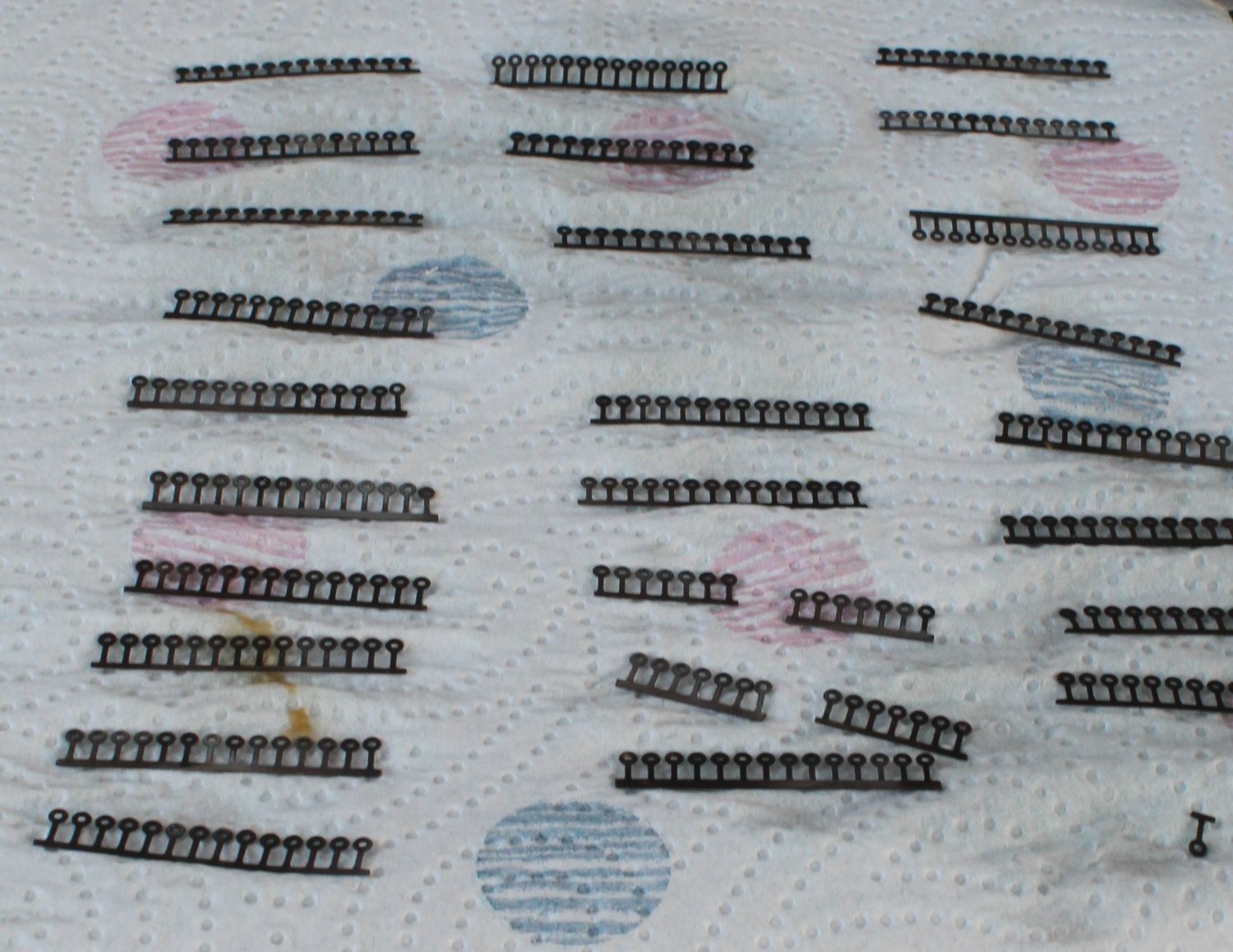
Working on a few strips at a time it did not take too long to complete the blackening process.

Starting at the first cannon position a micro drill bit was used to check each openings were clear and deep enough for the eyebolts. After a dry fit test each eyebolt was dipped in some ca glue and inserted into their respective holes. The first cannon position is now complete and looks good with the cannon dry fitted in position. Only another 25 more positions to complete.

Hi Ho Hi Ho It's off to work I go
- chris watton, Ryland Craze, CiscoH and 1 other
-
4
-
Painting Completed
A pleasant afternoon splitting my time between watching the open and applying coats of paint. As I removed the masking tape I was pleased that there very little paint leakage, and the excess paint was easy to remove with a bit of sanding.
I needed a steady hand to apply the iron black paint to the cap squares on each of the 26 off 24lb cannon carriages.
I then thought it would be a good idea to add a set of wheels to one of the cannon carriages, remembering to remove the laser char from the outer edge of each wheel before fitting. It is a really nice looking cannon.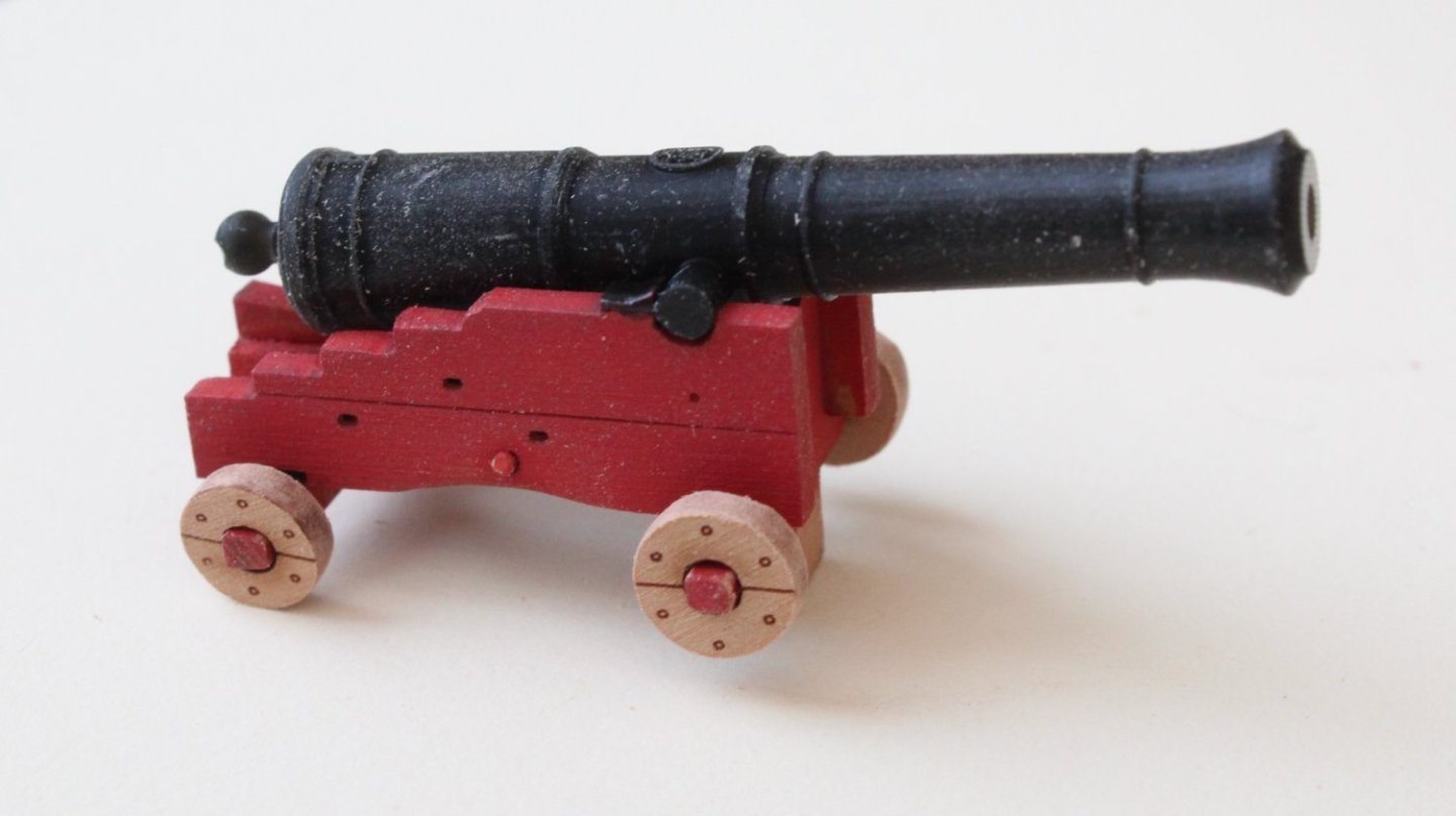
With regards to the cannon eyebolts to be fitted, there are 7 required per cannon carriage, 6 located on the bulwark and upper ledge patterns for each cannon carriage and 1 located on the gun deck for each cannon carriage .
There is a note supplied with the kit with regards to the eyebolts. I am not entirely sure what the 2 packs of 100 copper eyelets are for as yet, but the note indicates these are to be used for all the deck and lower top eyebolts. The note also states that the photo etched (PE-1) main eyelets are for all cannon associated eyebolts, i.e the 7 per cannon carriage, 6 per bulwark carriage position and 1 per gun deck for each cannon carriage.
Next it was time for a test fit on the gun deck. Everything looks good, noting there is some residual masking tape debris to clean away.


This weekend I will be on grandparent duty looking after a very active 2 & 1/2 year old. I'm not expecting to be able to spend too much time, if any, in the shipyard. The next planned task will be blackening and fitting 364 PE-1 eyebolts (14 PE-1 eyebolts per cannon, 26 cannons so 26 x 14 = 364) and fitting the cannon carriages wheels. I think will take quite a few days to complete. I might intersperse these activities with some other tasks to break up the monotony.
- davyboy, mgatrost, Edwardkenway and 4 others
-
7
-
Painting Commences
I have been debating if I should invest in a airbrush system which will probably yield much better results. However for the time being I will continue with using paint brushes.
I applied a coat of WOP to the all cannon carriages, gun port openings, inner bulwarks, spirketting and upper ledge patterns. Once the WOP had dried out it was time to start the painting process.
The cannons are looking OK after the first coat. One or two more coats will be required.
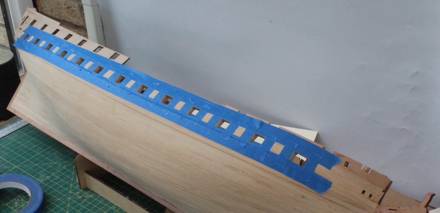
Next it was time to tape the Indy hull.

I started with painting the gun ports.
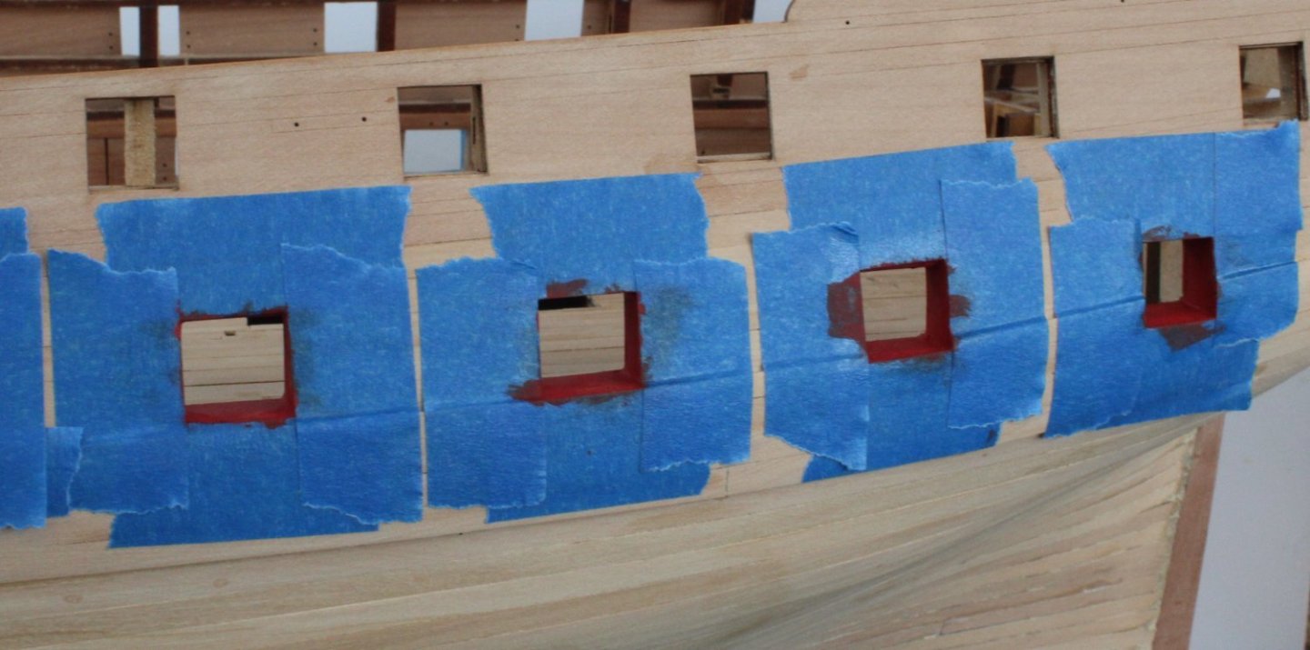
The Indy hull looks reasonably OK after the first coat of paint. Some more coats will be required however.

- glbarlow, chris watton, ccoyle and 9 others
-
12
-
32 minutes ago, chris watton said:
I always end up smearing on a little diluted wood filler in the frames, had quite a few for the Victory!
I remember doing the all the gun ports and adding linings on Caldercraft's victory, it was quite a task.
- chris watton, mtaylor and Mr Whippy
-
3
-
Painting Preparation
I am not going to rush the next stage which will be to paint the cannon carriages, gun ports and inner bulwarks.
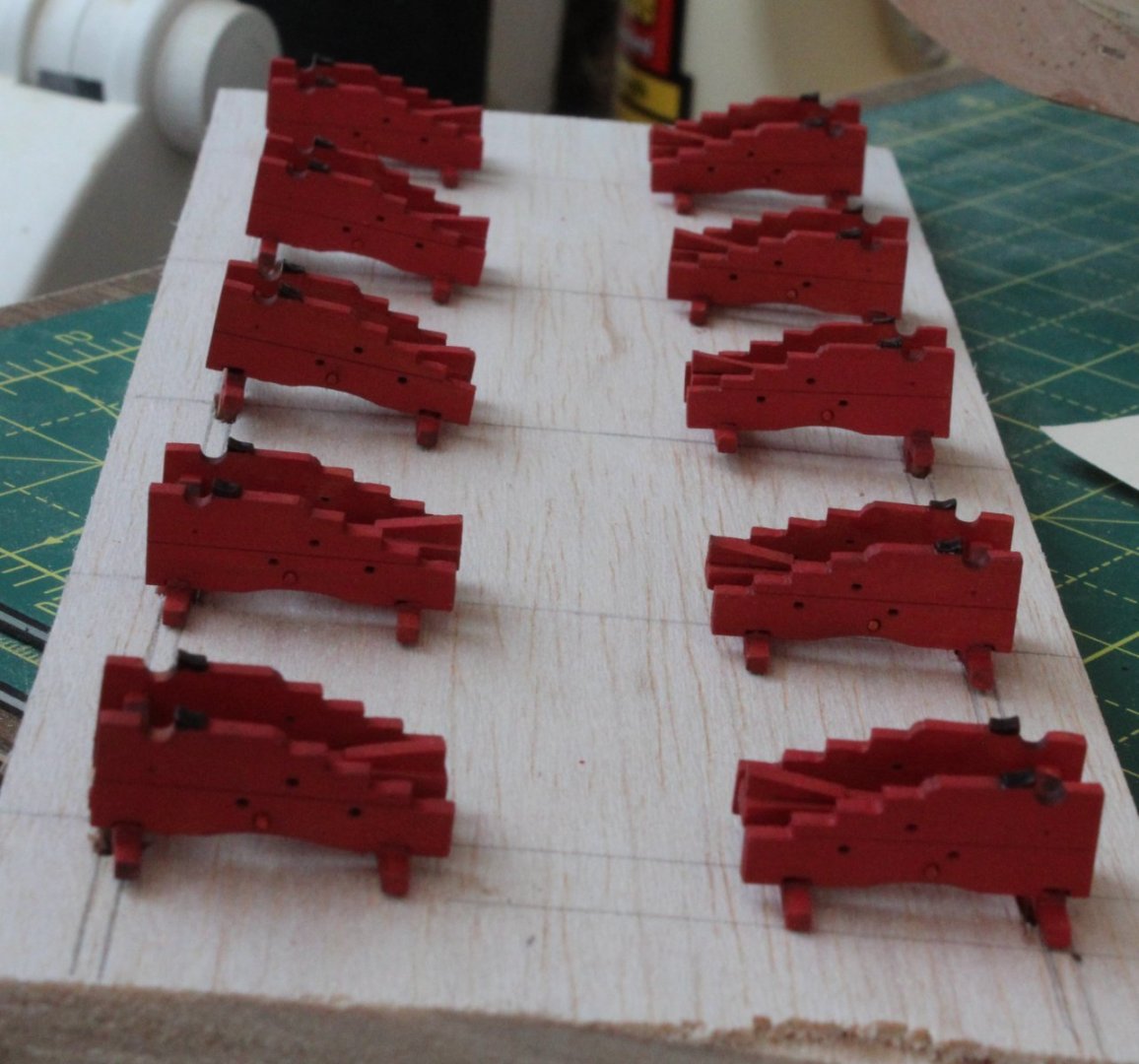
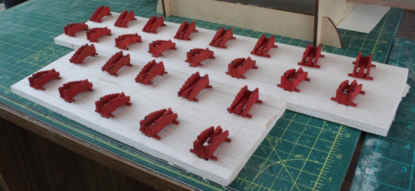
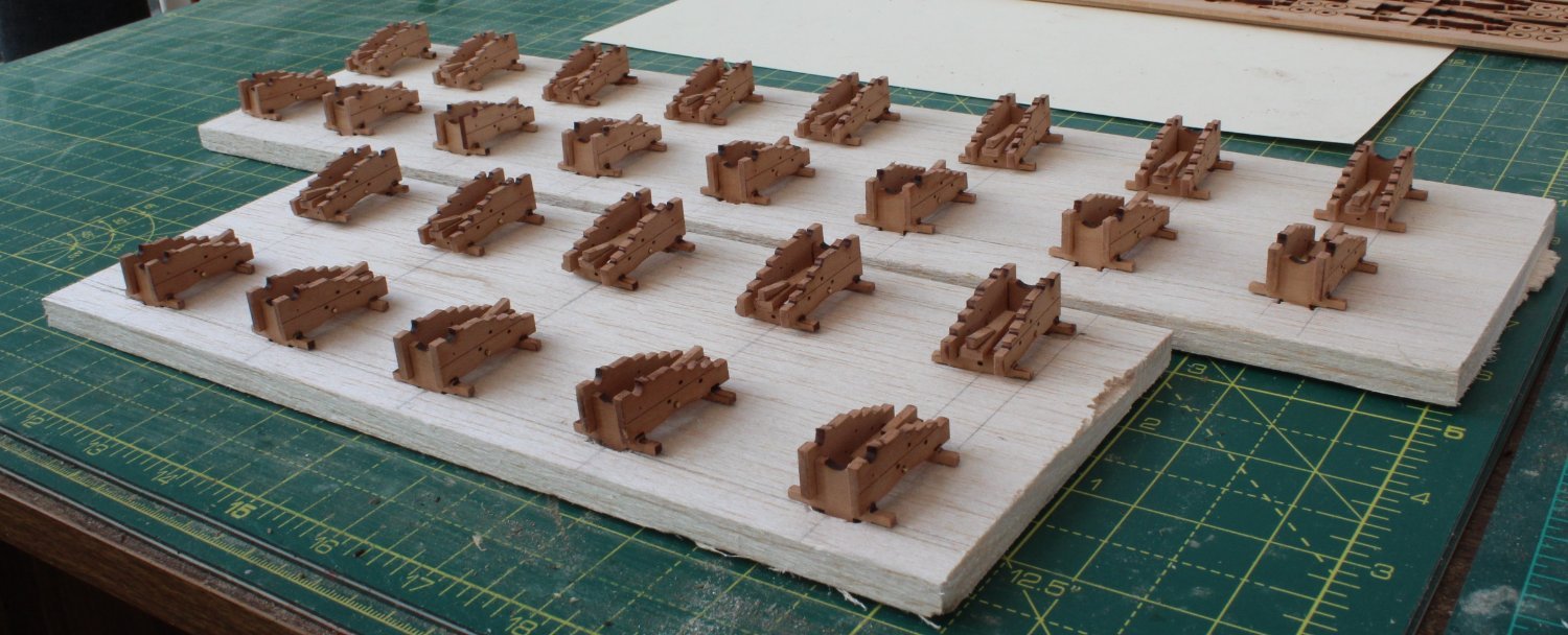
Using some balsa wood strips I made a couple of bases to hold the cannons in readiness of the painting. My painting plan fpr the cannon carriages is start with applying a WOP coat. Next I will spray paint with some Plastikote Red Oxide Primer. Finally I will add a couple of light coats of Tamiya Flat Red.
The cannon carriages are now ready and waiting!

I also inspected the gun port openings to made sure all looked good before painting them. As can be seen in the next photo one gun port opening required a bit more work.
I added a bit of wood filler, but as can be seen in the next photo there is still a little bit work required.

The next photo shows another gun port that requires a bit of wood fill attention.
Looks much better with a bit of filler added.
Once the wood filler has been given time to dry I will give each gun port opening a final sanding with some 400-grit sand paper and assuming all look good to my eye I can start painting.
- Edwardkenway, RossR, GrandpaPhil and 2 others
-
5
-
24lb Cannon Carriages
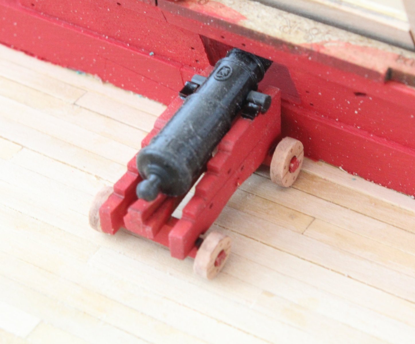
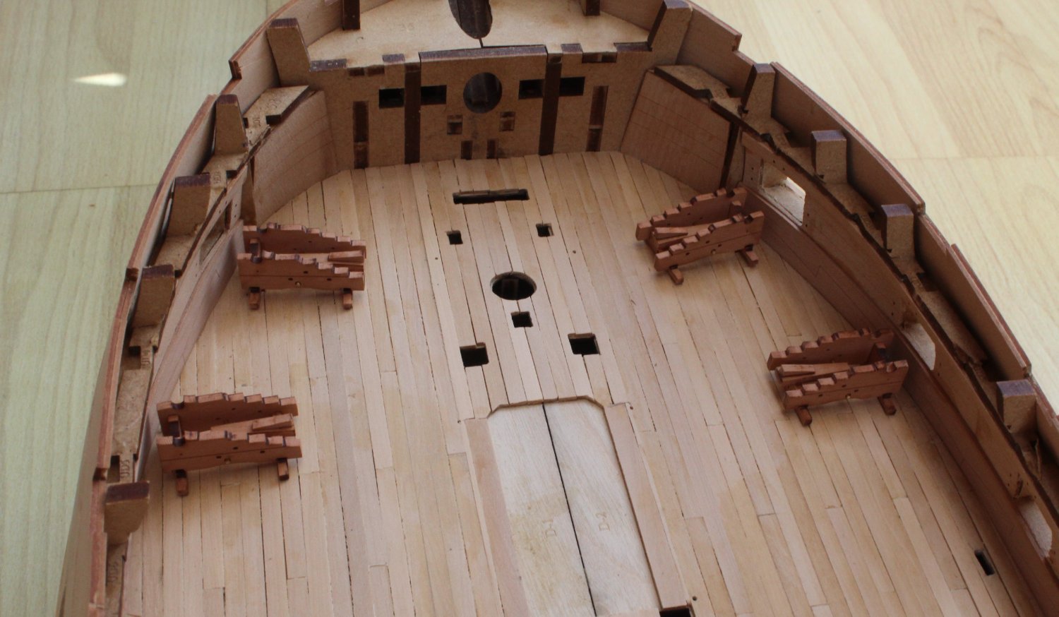
I have now completed the basic assembly of the gundeck 24lb cannon carriages. They are ready to be painted along with the gun port openings, inner bulwarks, spirketting and upper ledge patterns. As can be seen in the two attached photos the cannon carriage tabs all locate in the slots created when planking the deck with boxwood. Although the manual suggested using 0.8 brass rods to support the carriage stool bed and quoin assembly and I opted to use 1mm brass rod as it a better fit for the holes provided in the gun carriage side patterns.
- James H, chris watton, davyboy and 6 others
-
9
-
24lb Cannon Production (26 to make) - The Start
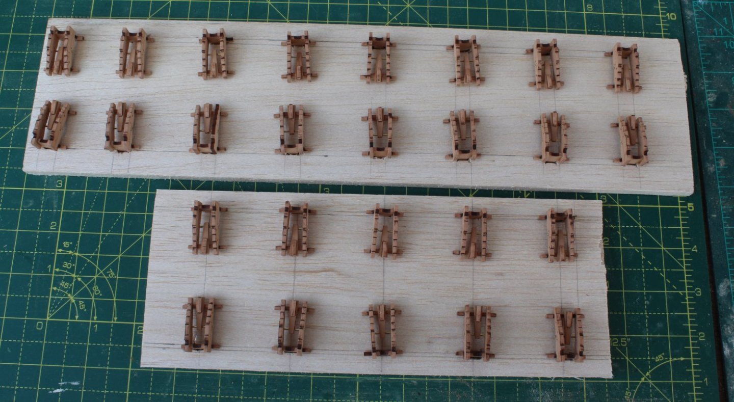
As detailed in my last post I built a simple jig to aid the assembly process of the 26 off 24lb cannons. With the front and rear axles loaded in the jig glue was applied to the joints and the two carriage side panels were added. The carriage sides were clamped to the front axle as the glue was curing.
I am really pleased that I invested time in building the jig as it has really helped me with the assembly process. In a short space of time the first 4 cannon carriages were assembled and they are now ready to be painted before the wheels can be added. I have found the ideal storage area for the assembled frames.
It was then time to book another river cruise along the Blue Danube from Budapest to Salzburg, via Vienna, departing middle of next month. After a spot of lunch the next cannon was added and the 6th cannon was assembled in the jig.

Production is going to stall due to family birthday celebrations (not mine) and visitors coming to stay for a few days. I am hopeful I can still sneak a few hours in the shipyard.
- Knocklouder, Ryland Craze, Rustyj and 5 others
-
8
-
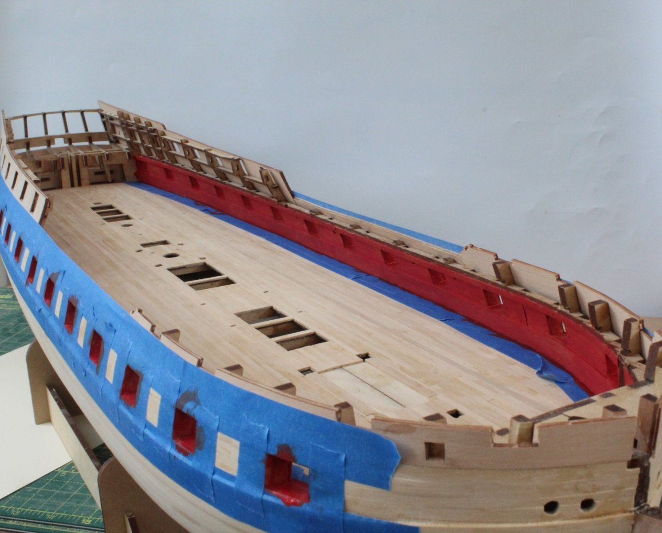
Spirketting and Upper Ledge Patterns
After giving the planked deck a good scrapping, I am now reasonably happy with the end result so I more inclined to add a WOP finish rather than a wood stain finish.
I decided that I would paint the inner bulwarks red after the spirketting and upper ledge patterns had been fitted. With the laser char removed from the top and bottom edges of the spirketting and upper ledge patterns it was a relatively easy task to glue and clamp the pattern in place. I have ordered some additional material with a view to adding a waterway between the gun deck and spirketting, therefore any paint seepage under the masking tape can be covered up.
I have added some photos of the spirketting and upper ledge patterns in place.
Cannon Assembly Jig
It is probably a bit OTT but I ended up making a jig to aid with the assembly of the cannons this afternoon. Starting with a base I cut a slot for the front axle gundeck locating tab, as shown by the blue arrow in the next photo. The yellow arrow indicates where the rear axle will be positioned. I added a side stop to ensure the rear axle is centrally positioned. This is not strictly necessary as I also added to side supports for the cannon side patterns.
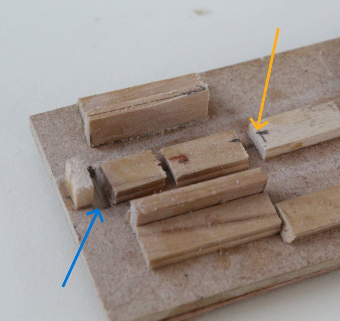
In the next photo the front axle has been added to the jig. I added a back and front to ensure the front axle is not leaning forward or backward.
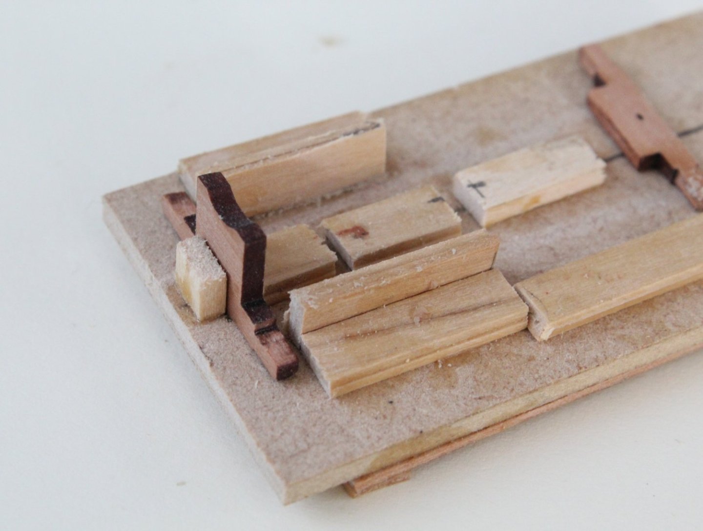
The rear axle is now positioned in the jig.
Next the first side pattern is added, making sure it is fully seated on the two axles.
The other side piece is now added to the jig.
In the above photo’s the cannon shown has only been dry fitted. I will try a test glued cannon assembly in the morning, and fingers crossed I will be able to release the assembled from the jig. As each cannon is in the jig the next cannon parts can be removed from the sheet and the laser char removed to allow time for the glue to grab. Once I have built the 26 off cannons they will be painted.
In the build manual a short length of 0.8mm brass bar is linked between the two side panels. Having checked the fitting I believe this should be a 1mm copper bar, has any of the other builder noticed this?


HMS Indefatigable 1794 by Glenn-UK - FINISHED - Vanguardodel Ms - 1:64
in - Kit build logs for subjects built from 1751 - 1800
Posted
Quarterdeck Deck Beam QD08
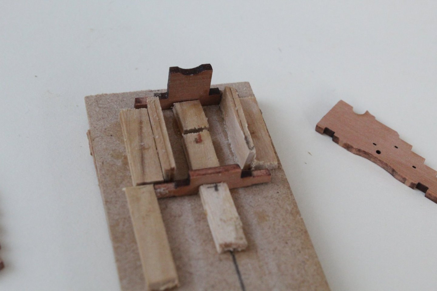
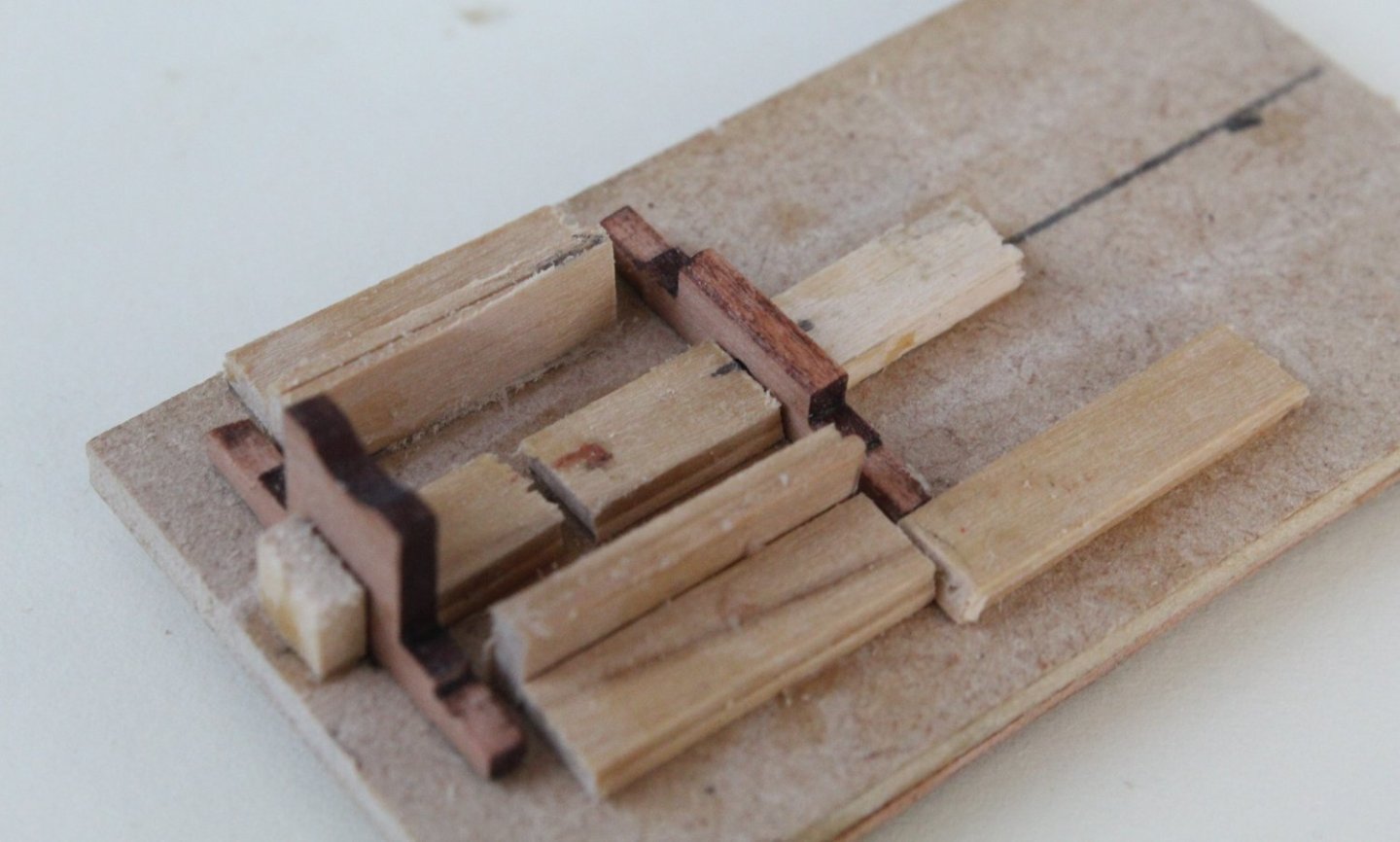
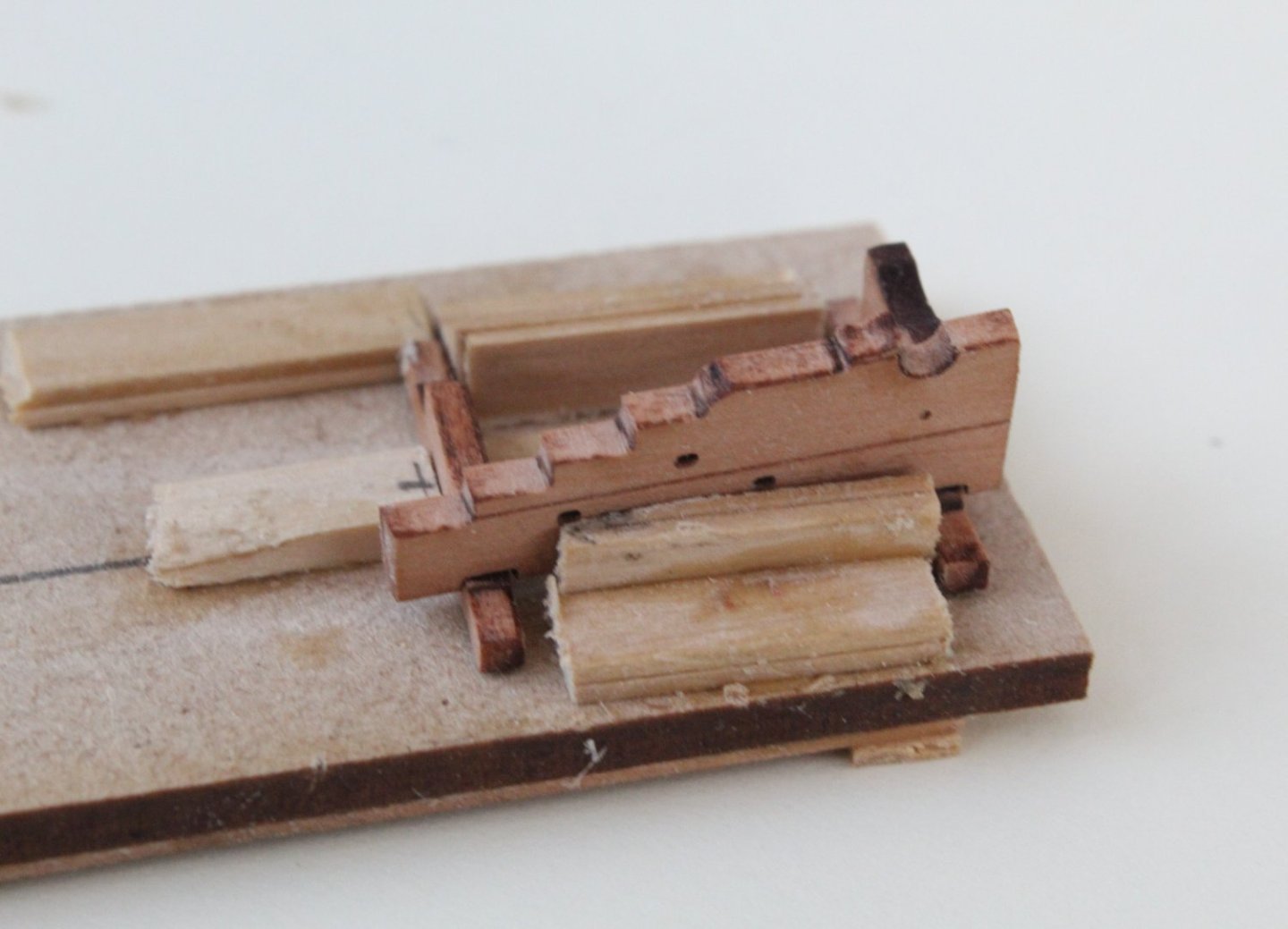
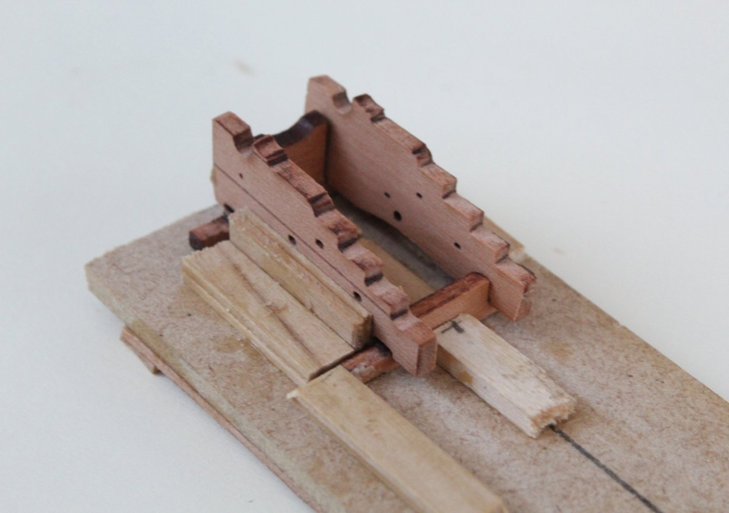
The quarterdeck deck beam QD08 comprises 4 separate patterns which have to be glued together, whilst clamped to a jig which applies a bend. In the following pictures I have just added the final QD08 pattern to the jig. The completed gundeck beam QD08 assembly will now be left clamped for the time being.
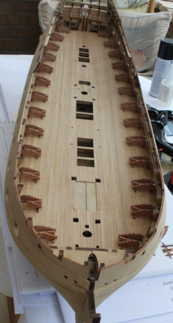
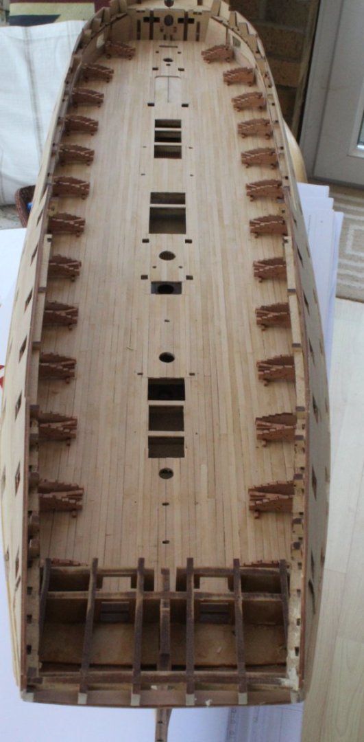
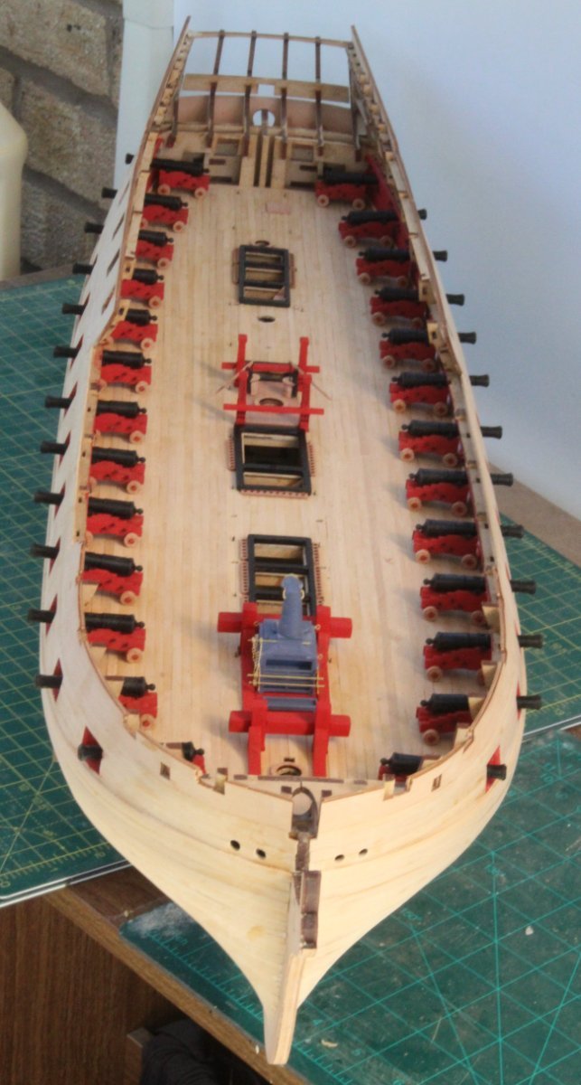
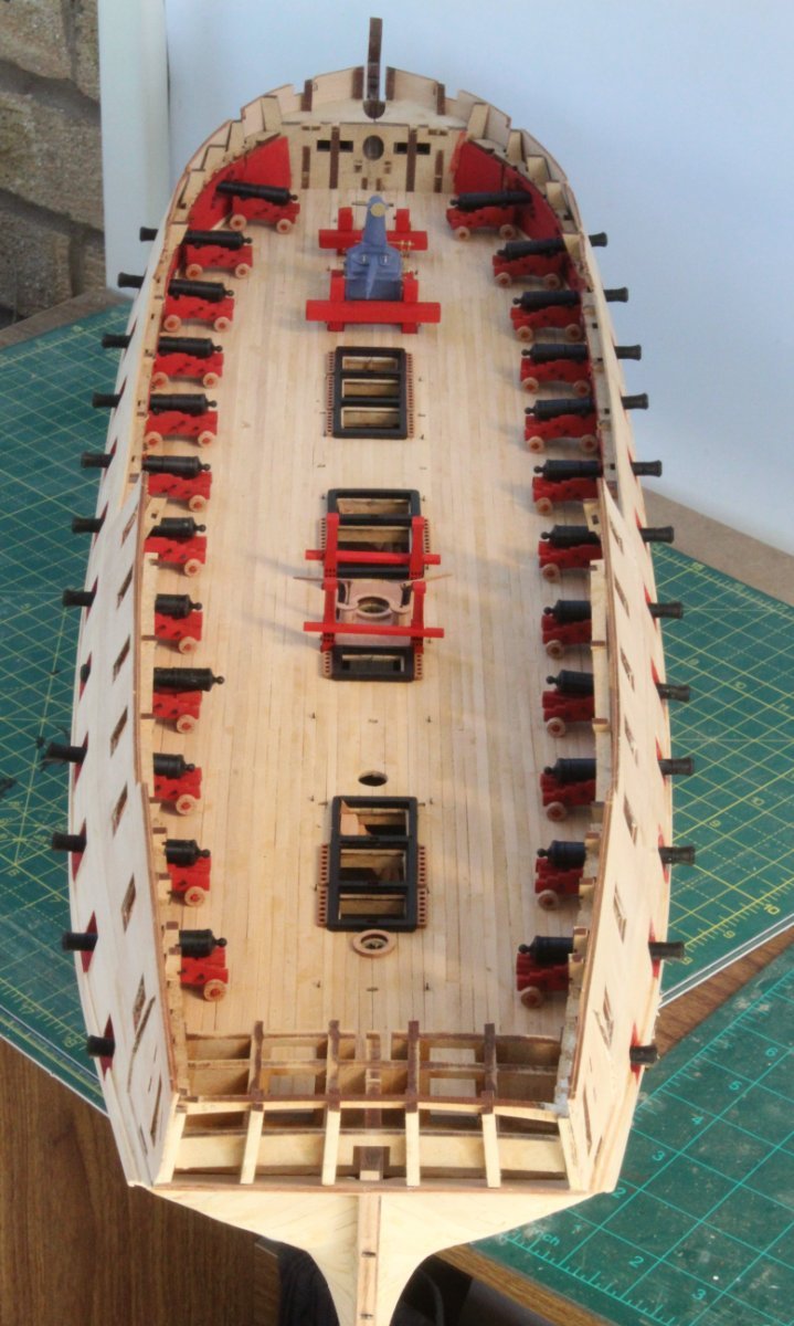
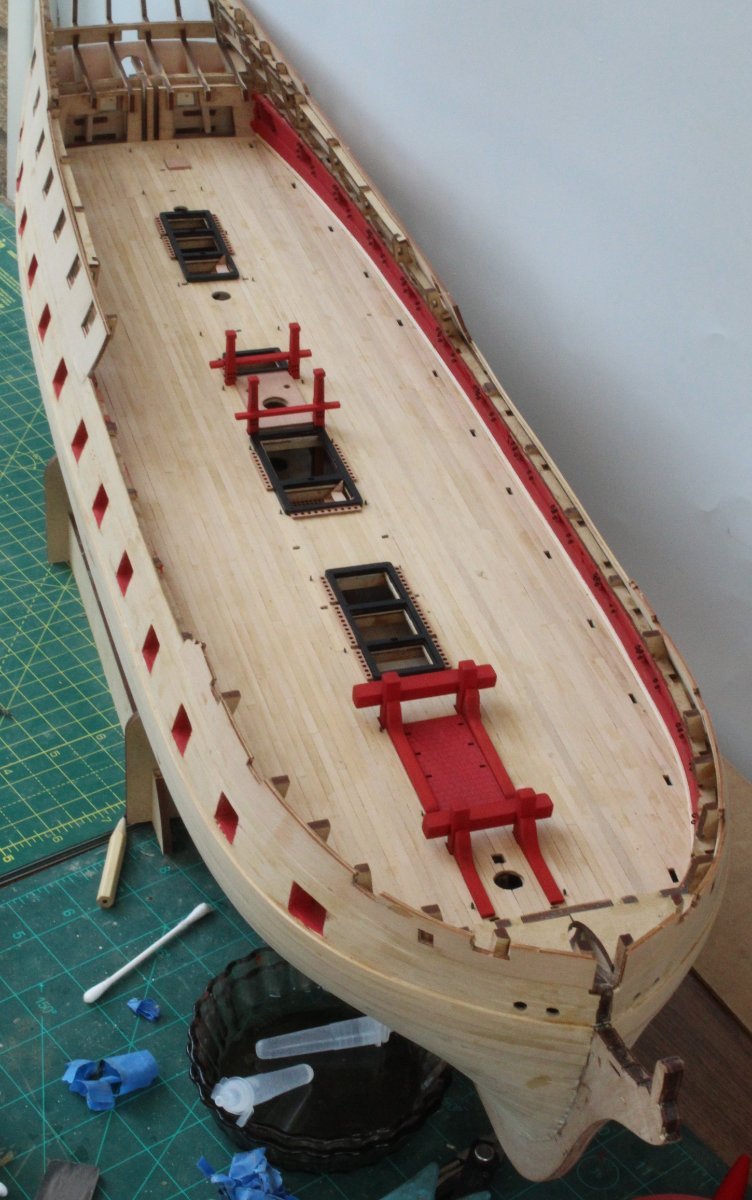
Completion of Gun Deck
I have reached another major milestone as I have now completed the Indy build up to and including adding all the gun deck items. It was a case of taking my time adding the various gun deck items today. In the attached pictures the deck beam pillars (located on the various hatches) are only dry fitted as they will need to be checked (and trimmed) for length as the deck beams are added. I had a senior moment when setting up the Indy for the following set of photos as I forgot to add the hatch comings although I did remember to add some dowels for the fore, main and mizzen masts.