


Glenn-UK
-
Posts
2,657 -
Joined
-
Last visited
Content Type
Profiles
Forums
Gallery
Events
Posts posted by Glenn-UK
-
-
When I started my last Indy build log I realised that I should have included some earlier build photos. Rather than post them out of sequence (OCD or what) I decided to delete and start again, sorry for the confusion. You will also note I have changed my user name to Glenn–UK.
Please find attached my first set of photos which represents what I achieved during week 1 of the build process.
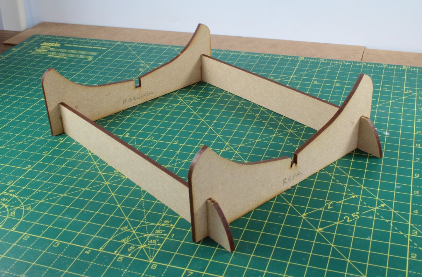
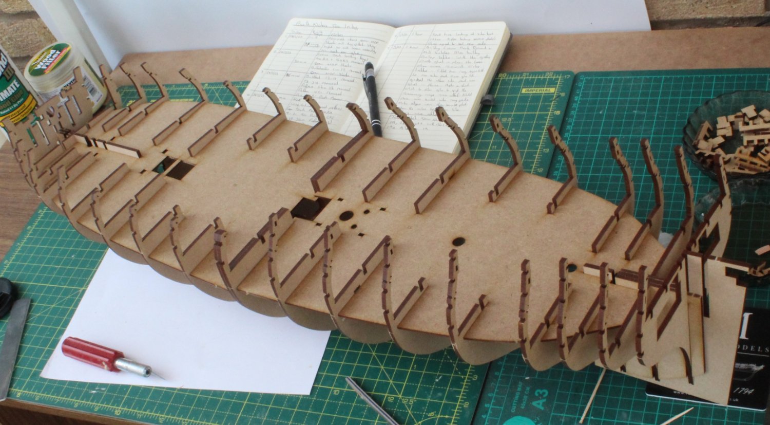
Photo 1 - The temporary build cradle
Photow 2 & 3- Fitting bulkheads to keel


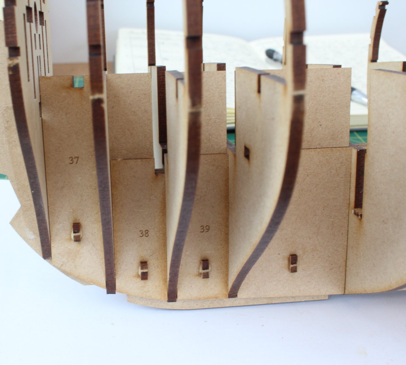
Photos 4 and 5 - Taken to check the bulkheads are correctly fitted
You will note there are 2 x bulkhead 9's which will aid the planking process later on in the build process.
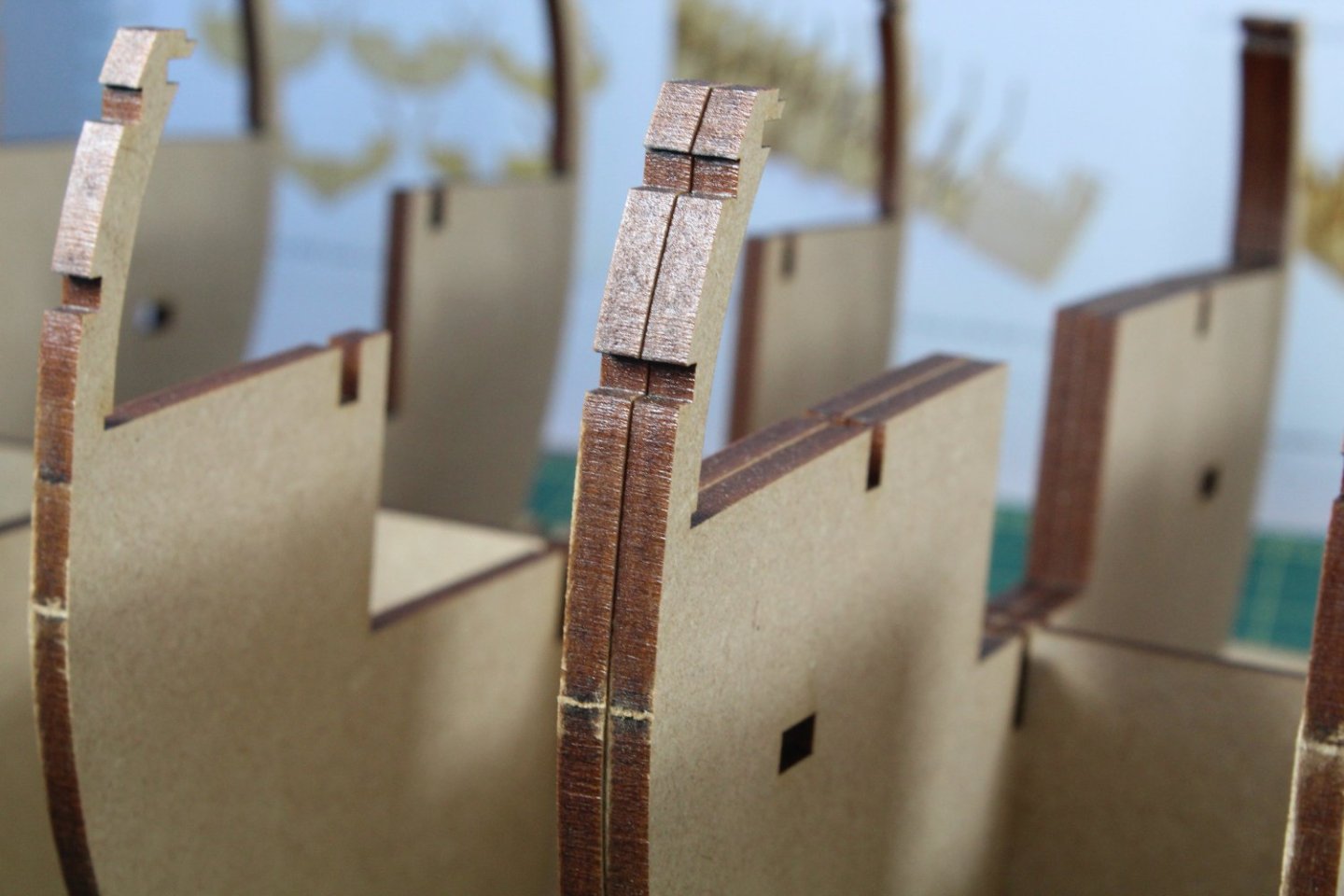

Photo 6 & 7 - Fitting side keel patterns
These keel side patterns are held in place with locating keys. This ensures these parts are correctly positioned when fitted.
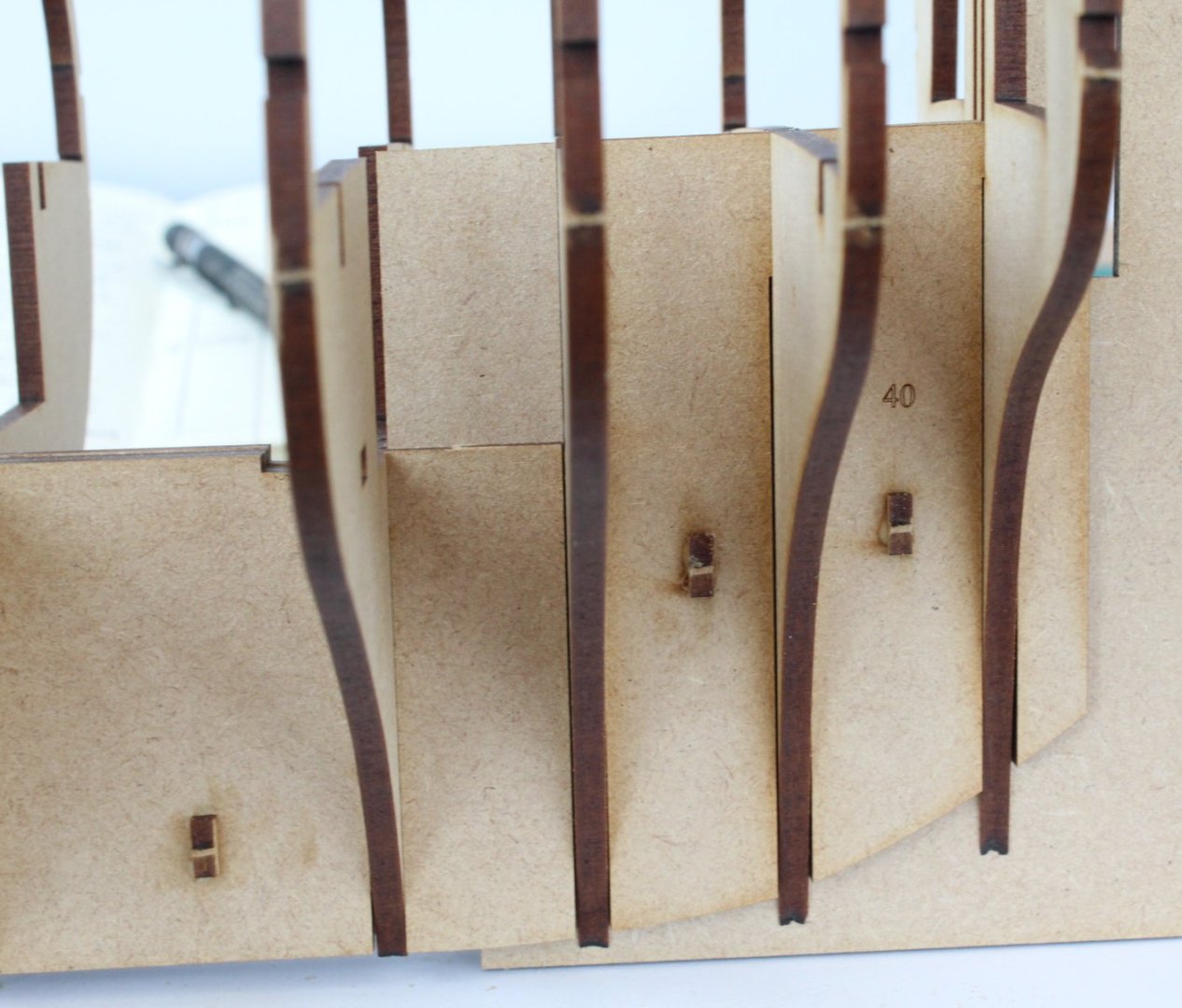

Photo 8 - Orlop Deck
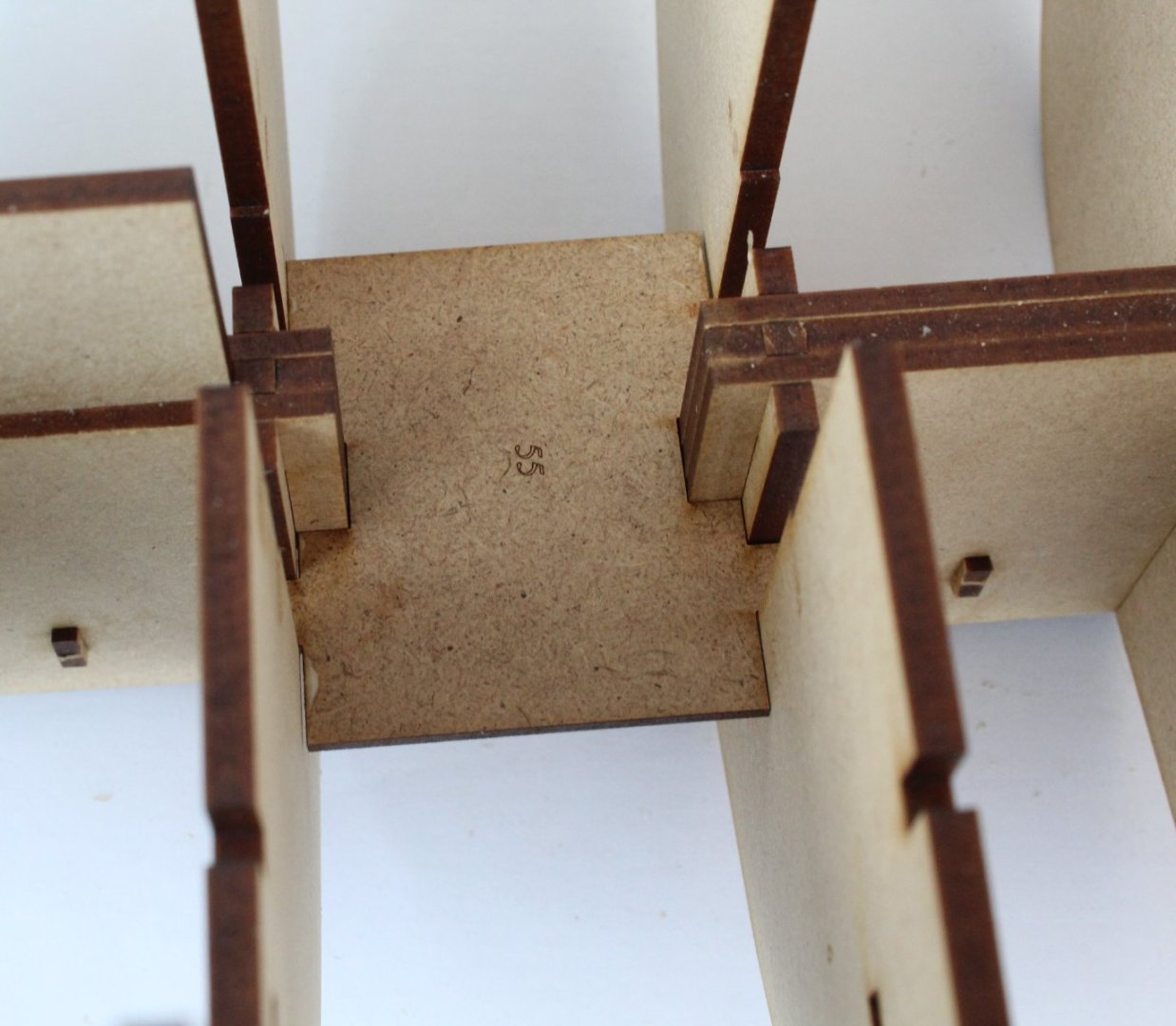
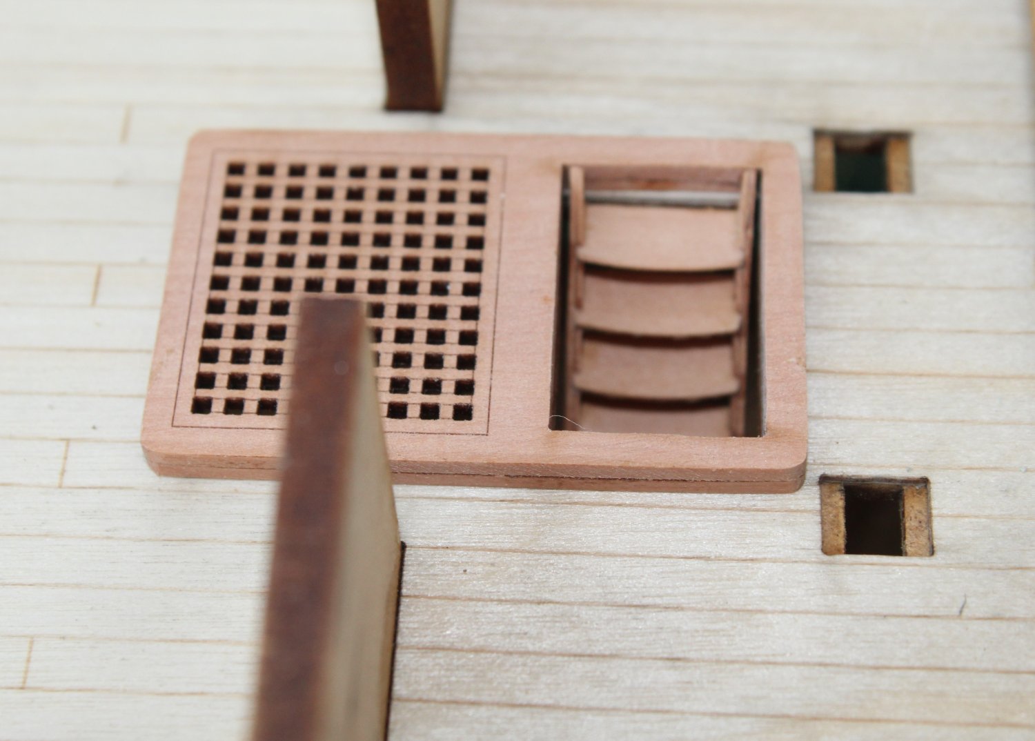
Photo 9 & 10 - Lower deck hatches and ladder.
The ladder photo was taken before the ladder side decorative patterns were fitted. Laser char was removed from the visible edges.
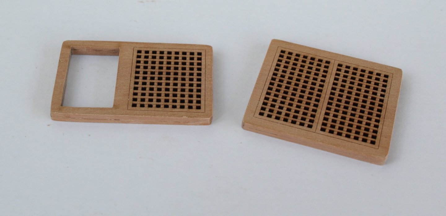
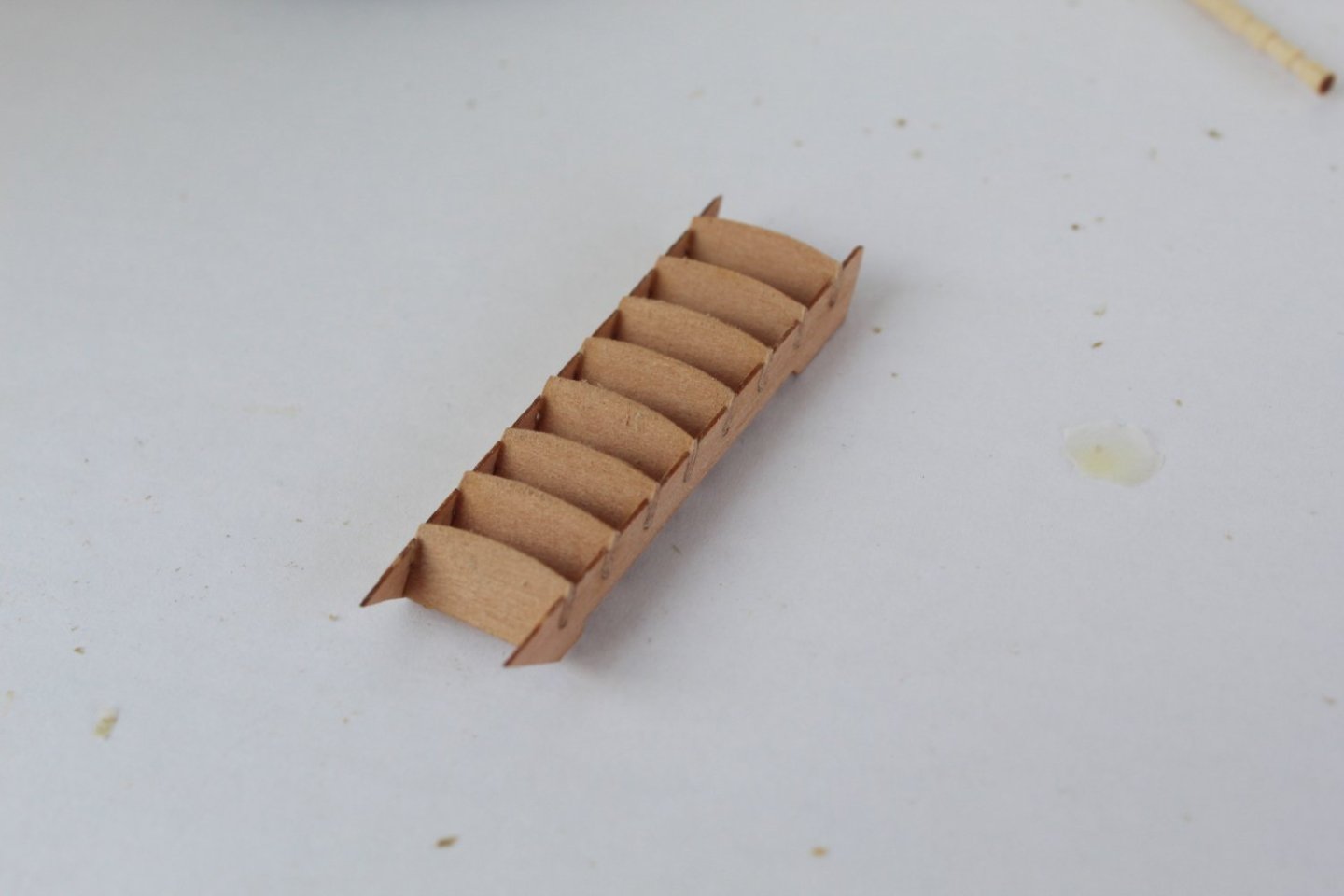
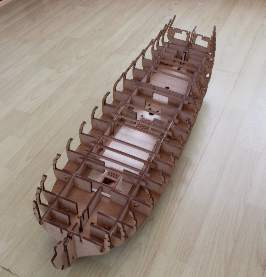
Photo 11 - Test fit of lower deck
There are two sections fore and aft. Locating keys will be pushed through some of the bulkheads to ensure the lower deck sections are held in position.

Photo 12 & 13 - Lower deck hatches and ladder fitted after deck pattern fitted
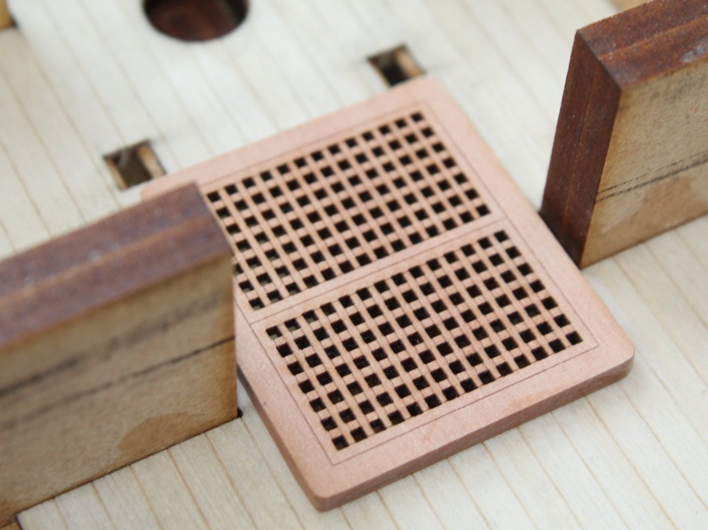

Photo 14 - Gun deck beams installed
- chris watton, markjay, Dave_E and 16 others
-
 19
19
-
Looking good, great progress
- Old Collingwood, hollowneck, Kevin and 1 other
-
4
-
-
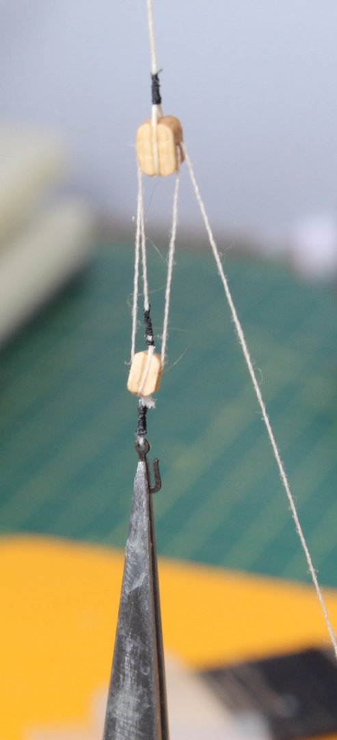
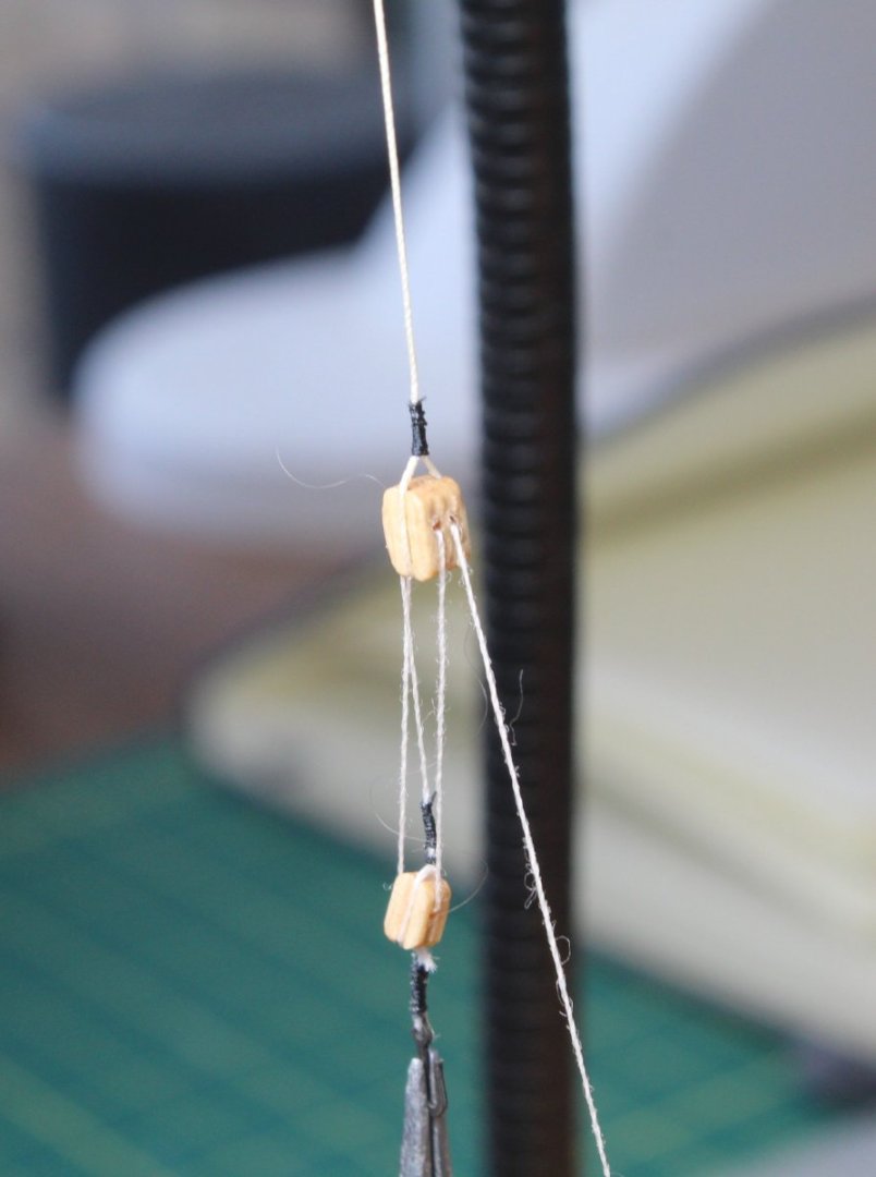
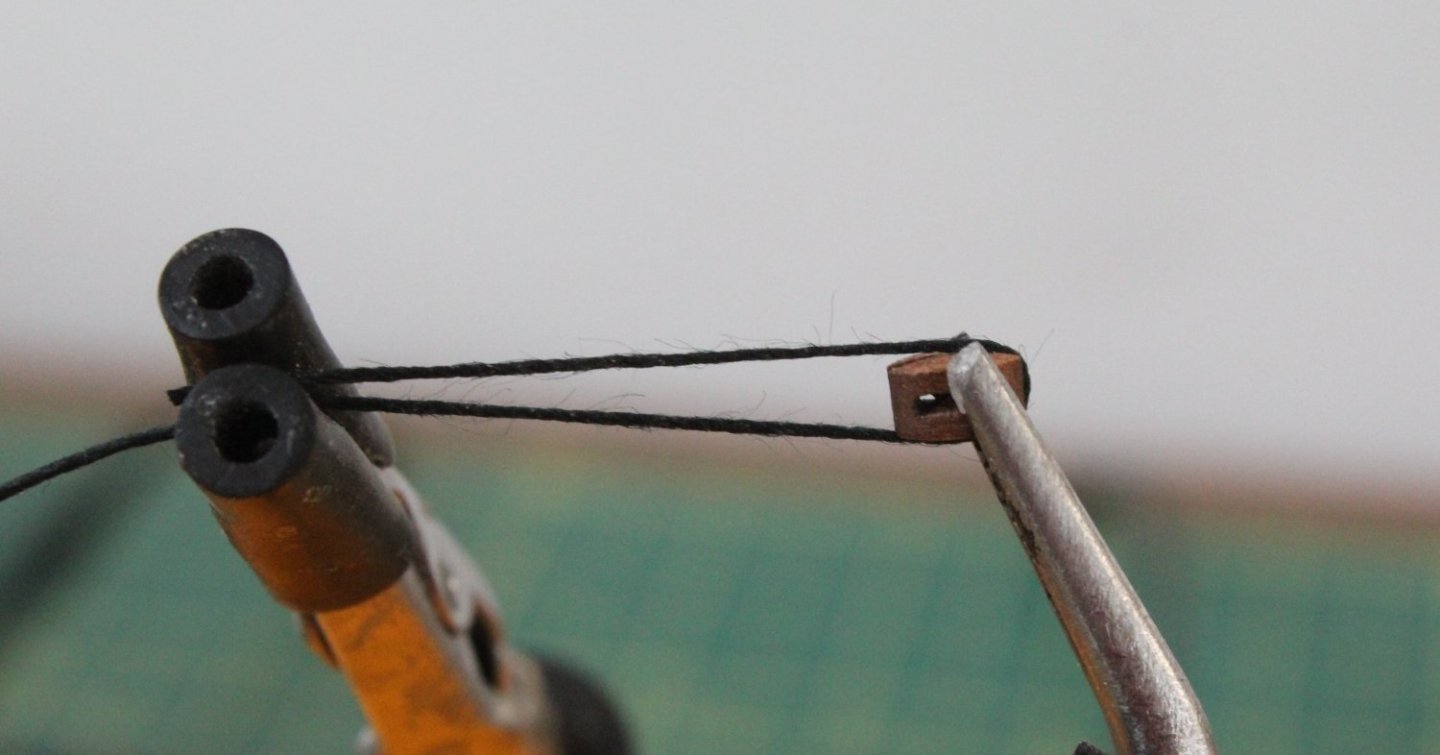
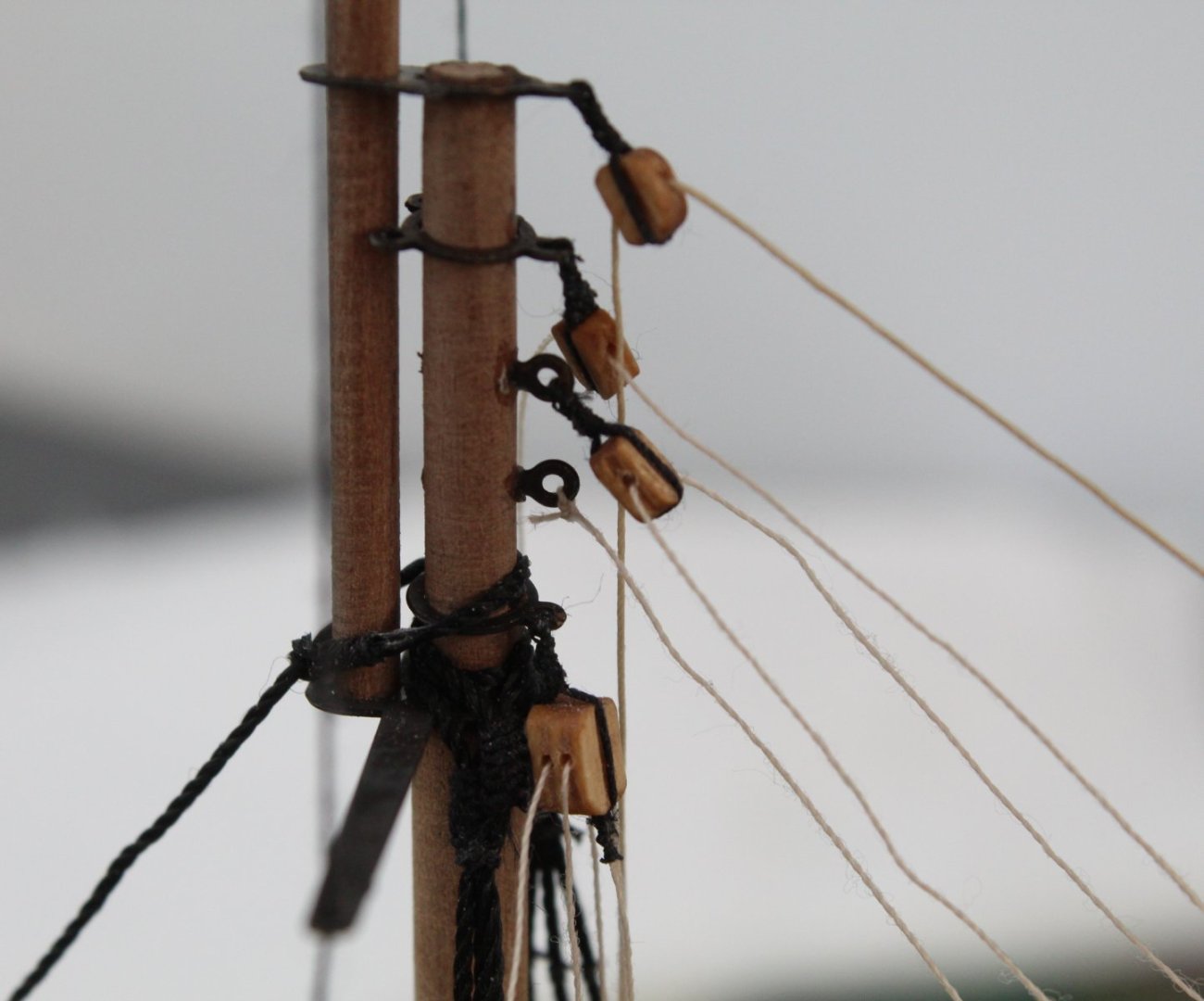
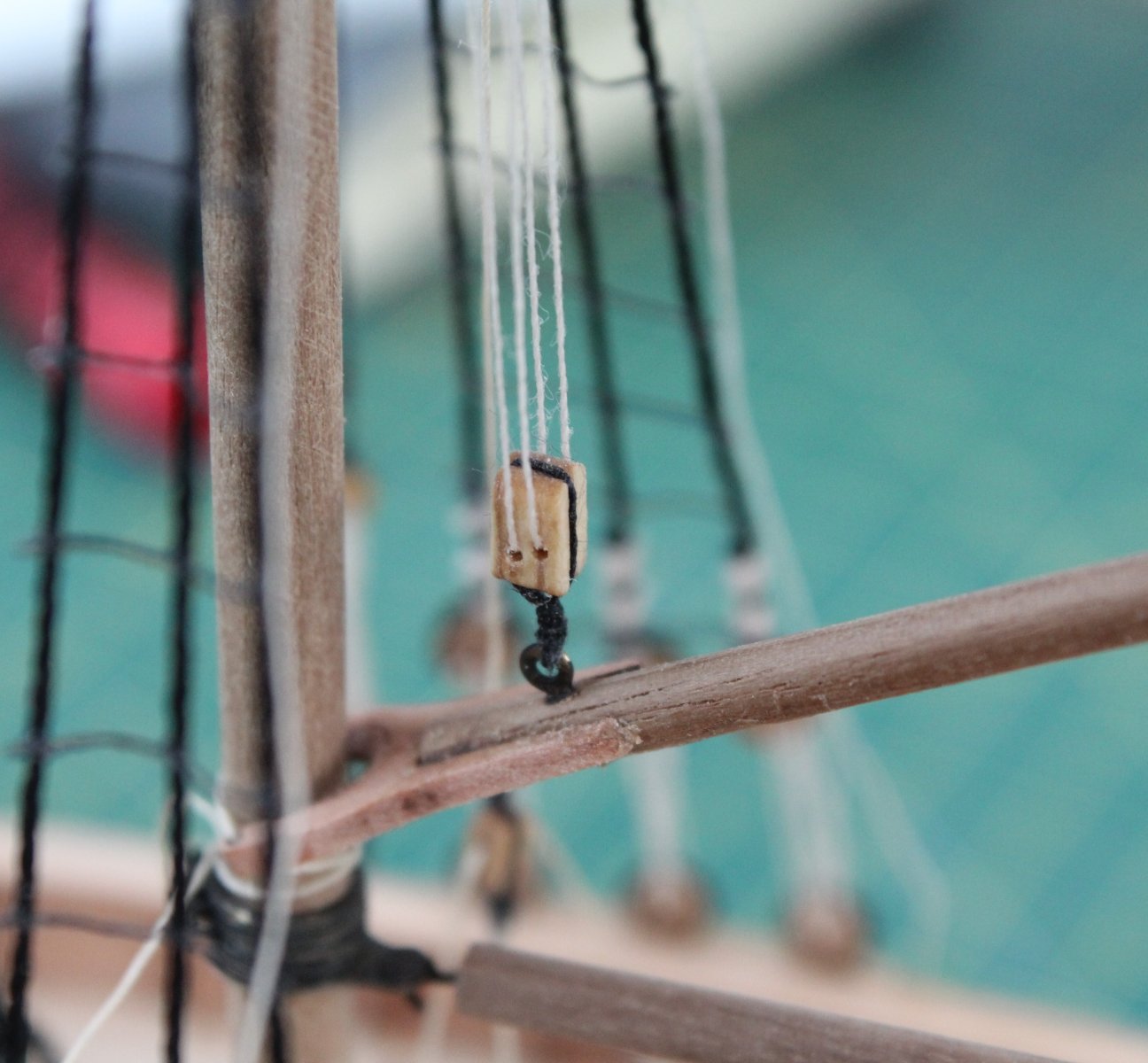
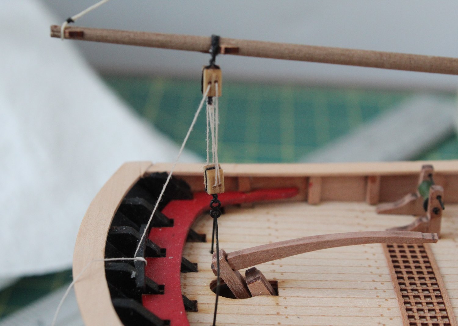
Continuing my quest to replicate some of the block rigging I noticed following a visit to HMS Trincomalee the next block I tried to replicate is a fairly common type of arrangement. Typically rigging from a mast or yard is brought down to deck level via a two block configuration. A double block is seized to the yard / mast rigging line and is then linked to a single block which is then hooked or secured to an eyebolt on the deck or side of hull.
I used 0.25mm natural thread for the mast / yard rigging line and 0.1mm natural thread for the inter-block rigging. I used black Semperfli Spyder 18/0 Black Fly Tying thread for the seizing. I have ordered some different threads and colours to try. I am more inclined toward a brown or beige thread for the seizing at the moment. I am reasonably happy with the replicated block arrangement, as shown in the next two photos. It needs to be a bit tidier around the base of the single block.
The next area I wanted to look at was the seizing of a deadeye to a shroud line. As can be seen in the next two photo's the seizing is quite elaborate.
@DelF provided an excellent example / tutorial of this type of seizing in his Speedy build log post.
Another example of this arrangement is shown on the following web site: San Diego Ship Modelers Guild.
I used a length of 0.75mm black thread for the simulated shroud line which was seized to a 5mm deadeye. I then attempted to replicate the shroud seizing, using 0.1 mm natural thread. On my first attempt I was not totally happy with how they looked. I also think I need to use a slightly thinner thread so I have ordered some fine Gutterman sewing thread which I will try when it arrives in a few days time.
On my second attempt I was much happier with how the seizing looked and I also seized the top of the free shroud end, using grey fly tying thread. However I didn't get the spacing between the two seizing's right as I added downward loops instead of upward loops on the second seizing. I think I now have a workable method for replicating the seizing's.
Each seizing currently comprises 5 loops but I may need to add one or two more when using thinner thread. It does take more time and effort to implement but I think the end result is much more pleasing to the eye. I will try a few more times once the Gutterman fine thread arrives to try and perfect the method and spacing. Of course this could become a nightmare to implement when I try to replicate this method on an actual model.

- Ryland Craze, Knocklouder, BenD and 3 others
-
6
-
-
She looks great, well done.
- FriedClams, usedtosail, Keith Black and 1 other
-
4
-
19 minutes ago, barkeater said:
Thanks for posting the pictures. I'm a little further from Portsmouth. 😁
Richard
Hello Richard. The Trincomalee is located in Hartlepool and I live in Scarborough which is only 70 miles away. Portsmouth is the other of the country about 300 miles. My wife and I will plan to take a short holiday later this year as there are few places we would like to visit.
-
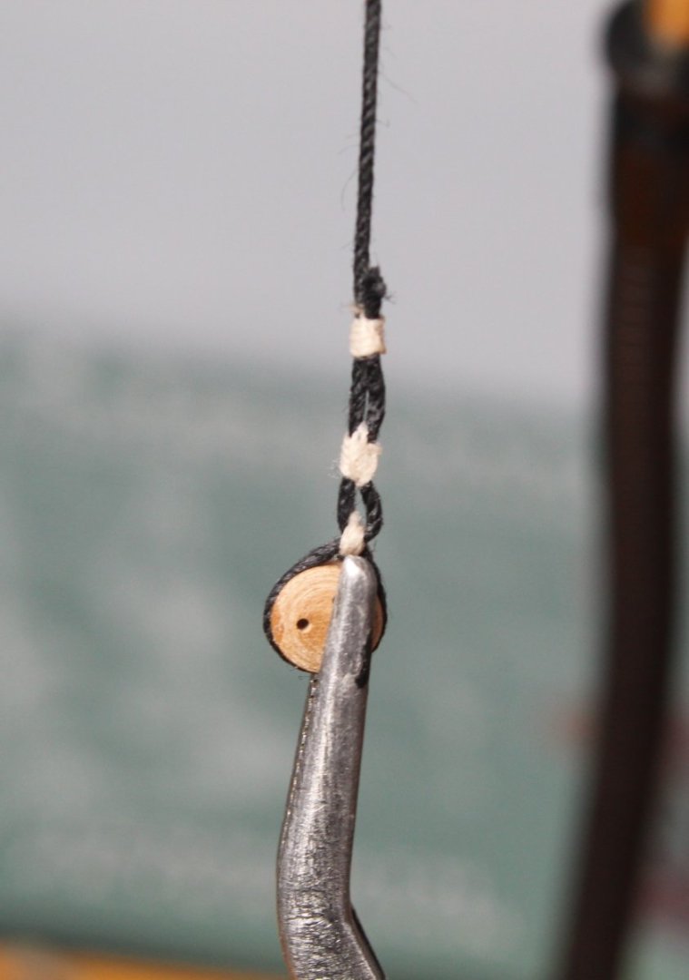
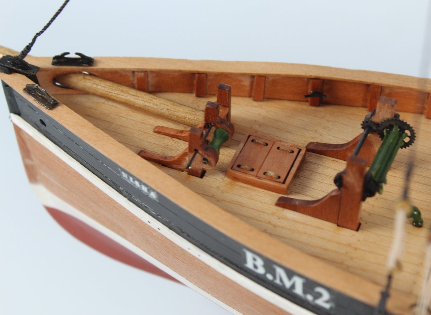
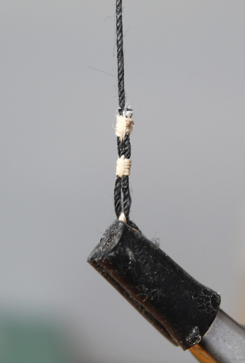
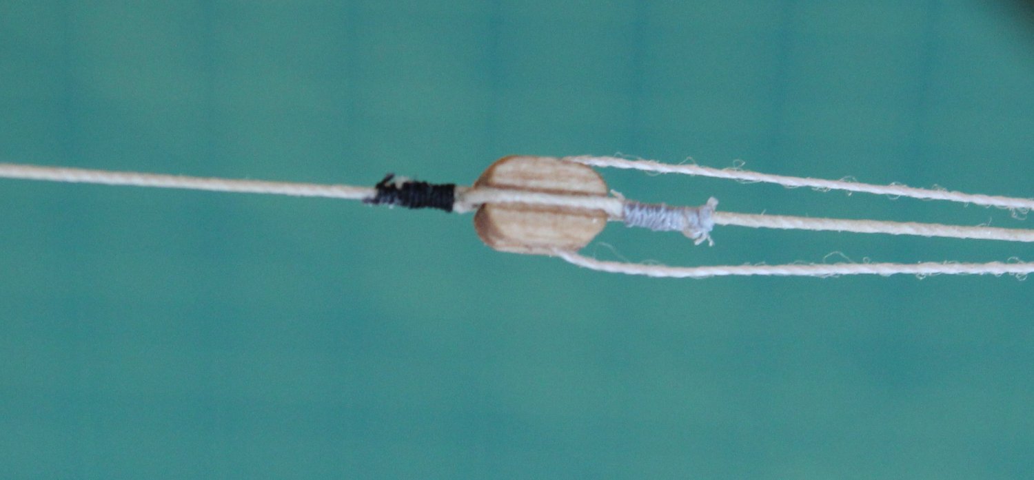
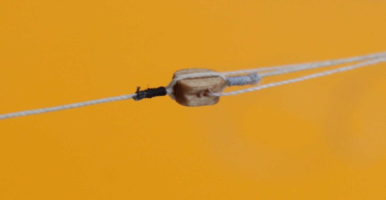
Following on from my earlier post I have now attempted to replicate another Trincomalee block. This time the block I am replicating is a very simple one, as shown in the following photo.

The next photo is my replicated effort. I have detailed all the steps I followed to achieve this in this post.
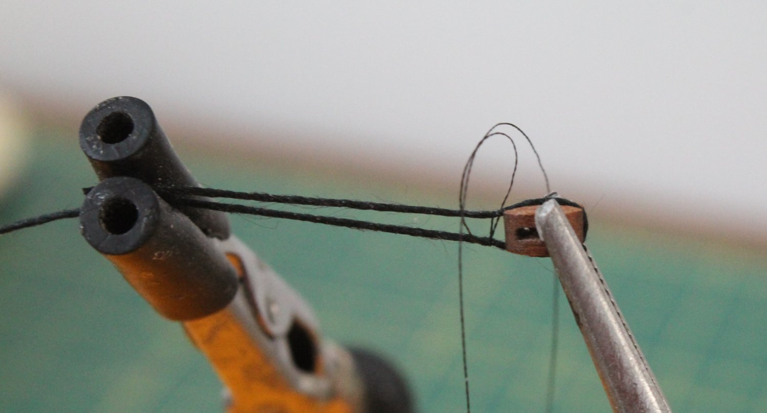
I started with holding a 5mm single block in my quad hands and I then wrapped a length 0.5mm black thread around the block.
For the seizing I used black Semperfli Spyder 18/0 Black Fly Tying Thread. I started with half hitch which is positioned on the underside.
I then placed another half hitch, but this time it was place on the upper side, as can be seen in the next photo.

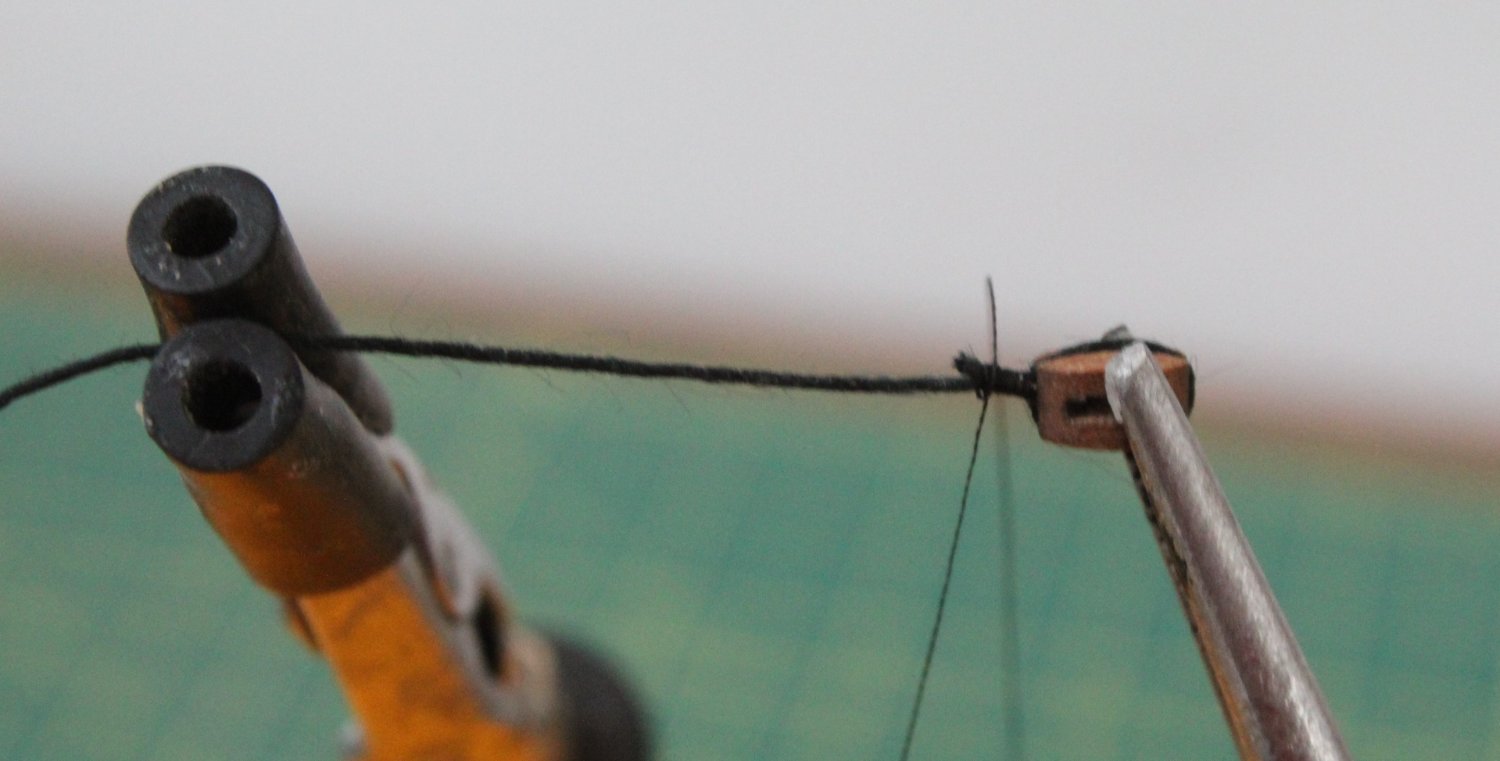
I then repeated this process until I added 15 half hitches on the bottom and 15 half hitches on the top.
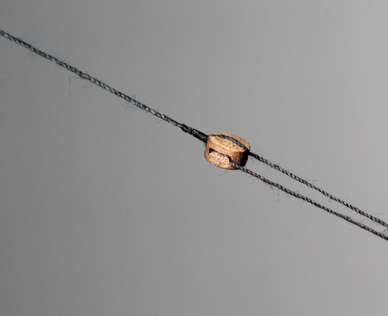
Next seizing is pushed right up to the block and the short free end is trimmed.

I then continued to add more top and bottom half-hitch knots (20 in total on top and 20 on the bottom). A touch of ca gel is applied to the seizing and the excess thread is trimmed. I have ordered some Floo Gloo which is fly tying cement which I am going to try.
To complete the process I added a small length of black thread through the block hole and then held it in position with the quads hands for the final photo which is reasonable copy of the Trincomalee block.
- Ryland Craze and AJohnson
-
2
-
1 hour ago, AJohnson said:
Looks like you had a great day Glenn, very envious, its been years since I last was up there.
Hello Andrew
It only a 70 mile drive from where I live so I should go more often as it was a few years ago since my last visit. I found it very informative. I would like to go back to Portsmouth to look around HMS Victory.
-
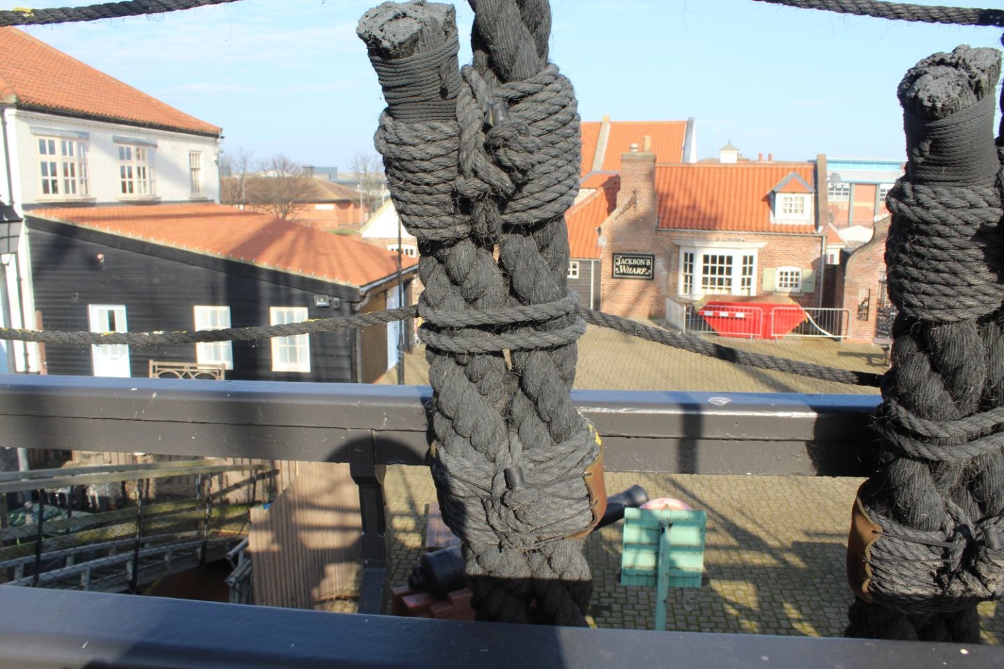
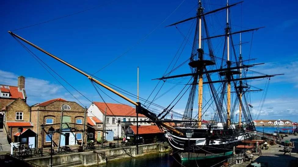
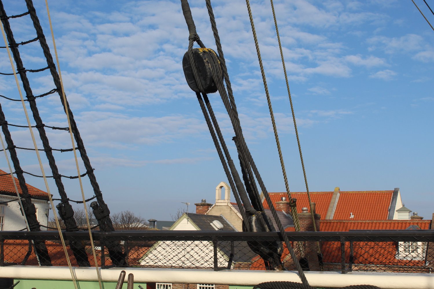
I visited The National Museum of the Royal Navy Hartlepool to have a look around HMS Trincomalee which is a Royal Navy Leda Class sailing frigate built shortly before the end of the Napoleonic wars. It is well worth a visit.
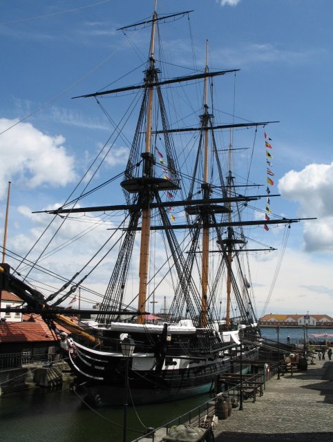
Part of the reason for the visit was to look at the rigging to see if I could improve my methods in readiness for my next project which will be the HMS Indefatigable. I am fully aware that the Indy is a different class of ship to the Trincomalee. Also the Trincomalee, being a museum exhibit, has undergone a lot of restoration work. .
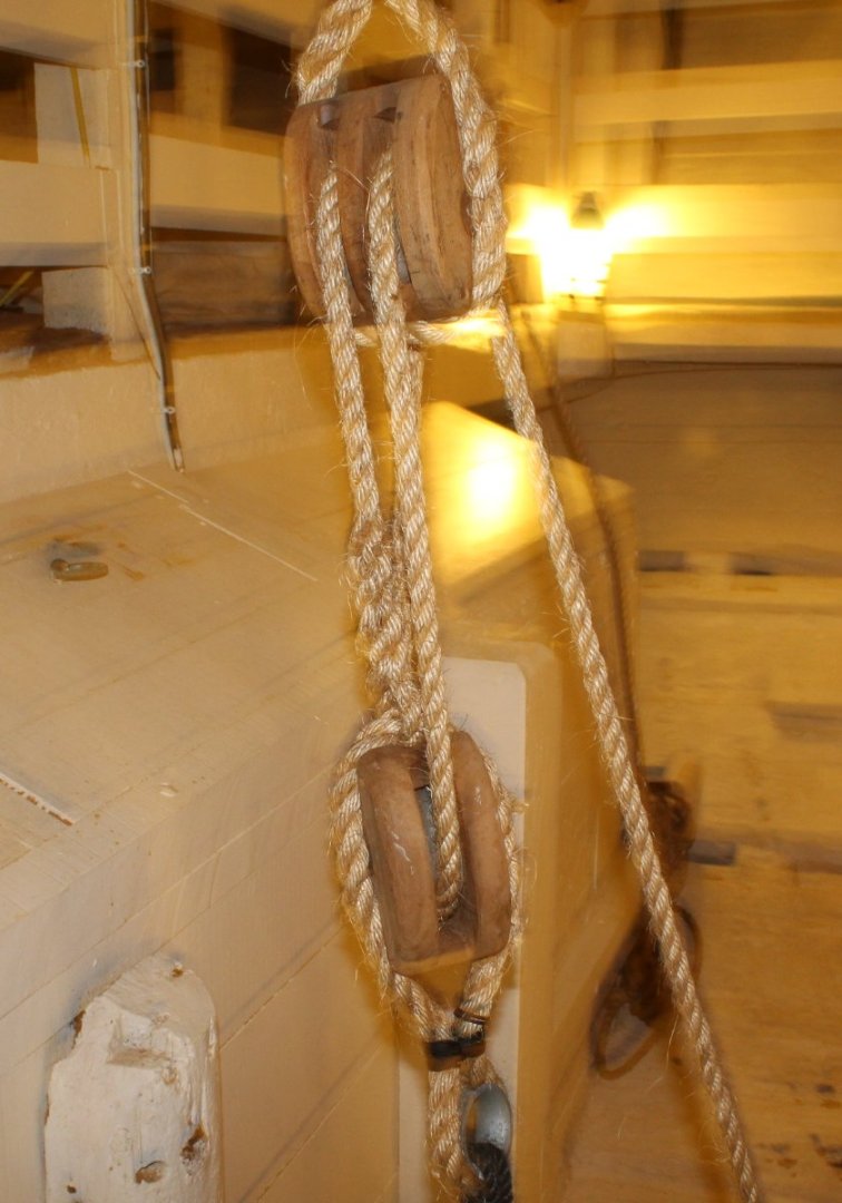
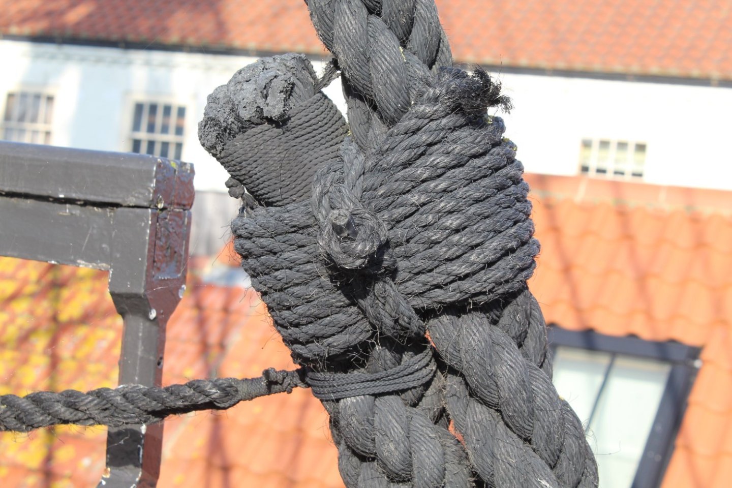
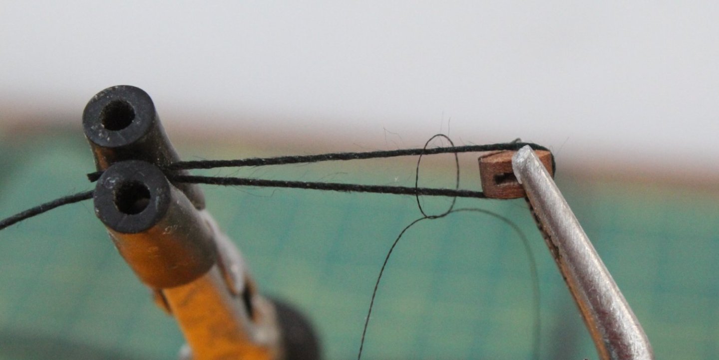
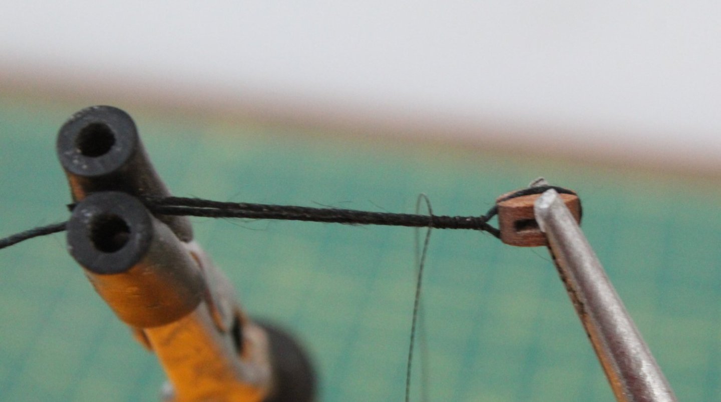
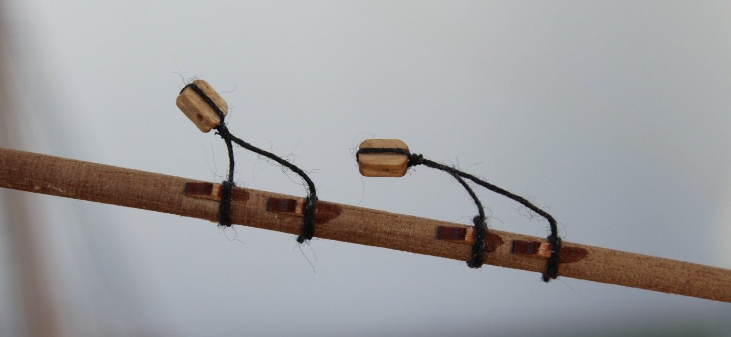
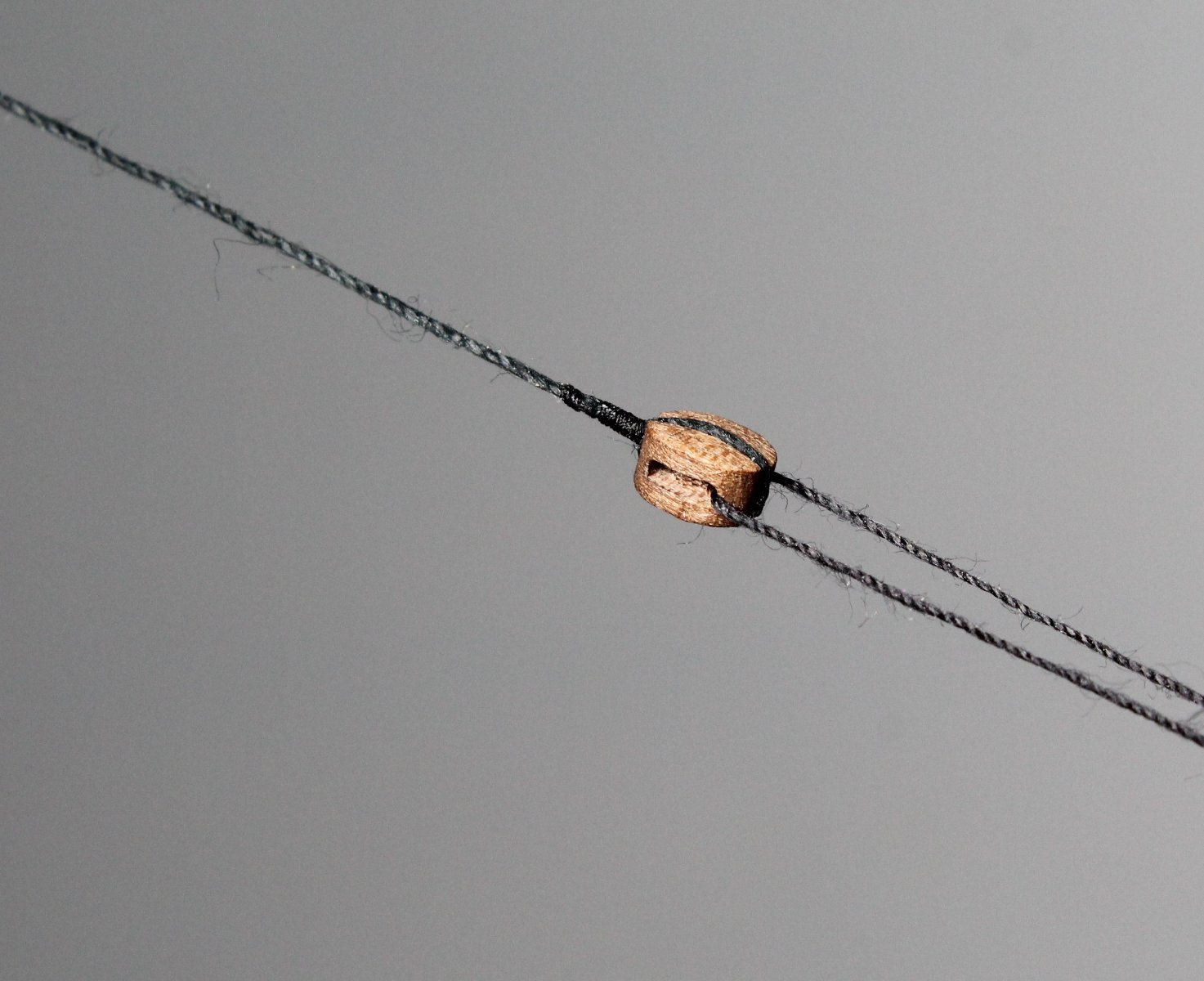
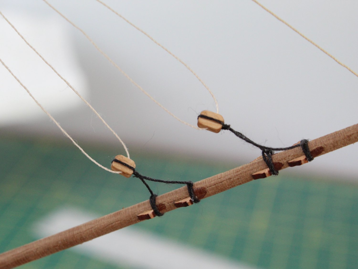
I took plenty of photo's of various aspects of the rigging (and belaying) and it quickly became apparent that there were plenty of things I could do which would yield better results. With that in mind, and knowing it will be a couple of weeks before the Indy kit is released, I thought I would experiment to see what I could do better. When looking at the following photo I noted that the rope used to seize around the block had been served. I also noted that just have much more the rope was seized compared with what I would normally do.
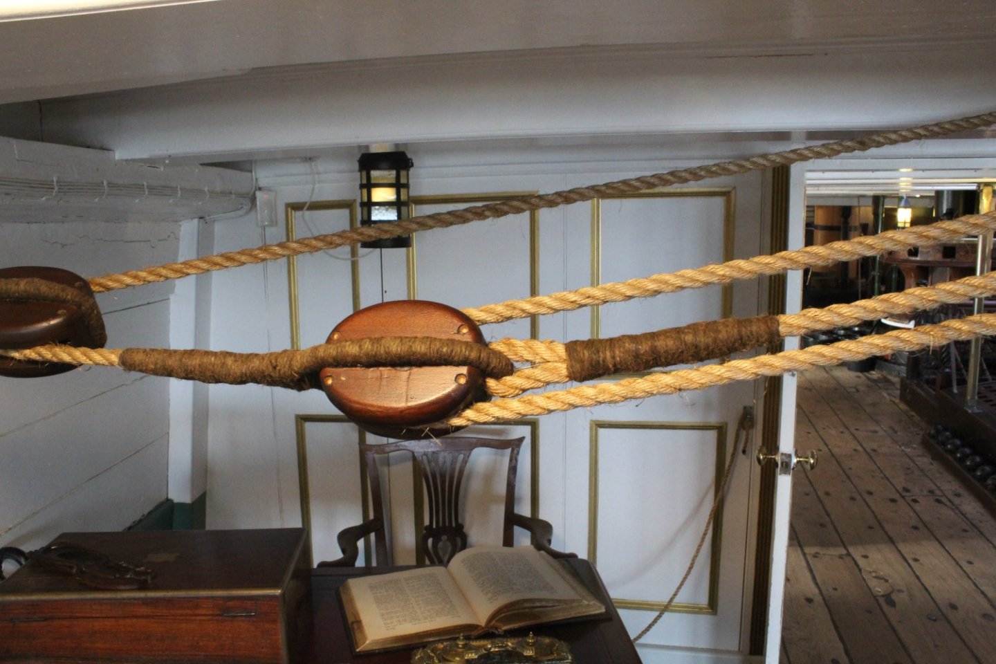
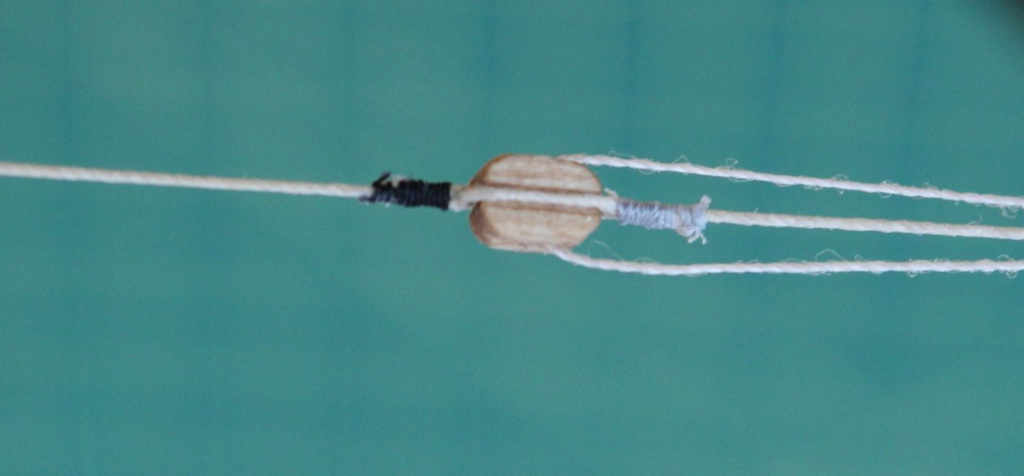
I decided that using a served rope around a block was not something I was going to replicate. I did however try extend the amount of thread seized and I also ensured the seizing extended past the cut ends of the thread. In the two pictures below I used 0.25mm natural thread which was seized using unwaxed Semperfli Spyder thread. I used grey spyder thread at one end and black spyder thread at the other. I think the grey looks better with the natural thread. I am going to order and try some differ spyder thread colours as there is a nice looking brown spyder thread which I think will be a mch better option. In the following two photos the seizing consisted of alternate half hitch knots 16 on the bottom and 16 on the top. I probably could have added a few more to extend the seizing even further which is something I will experiment with over the next couple of weeks.

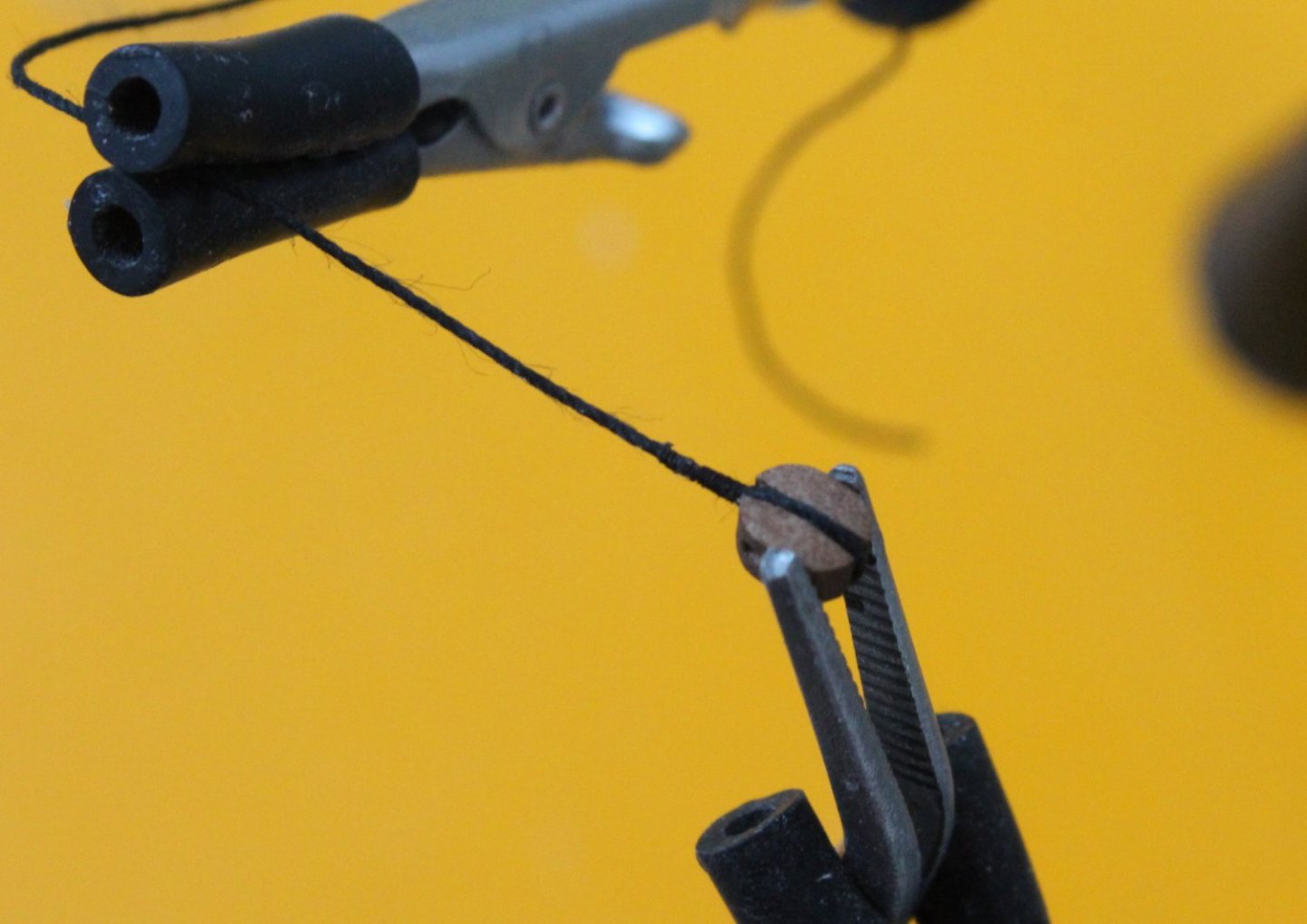
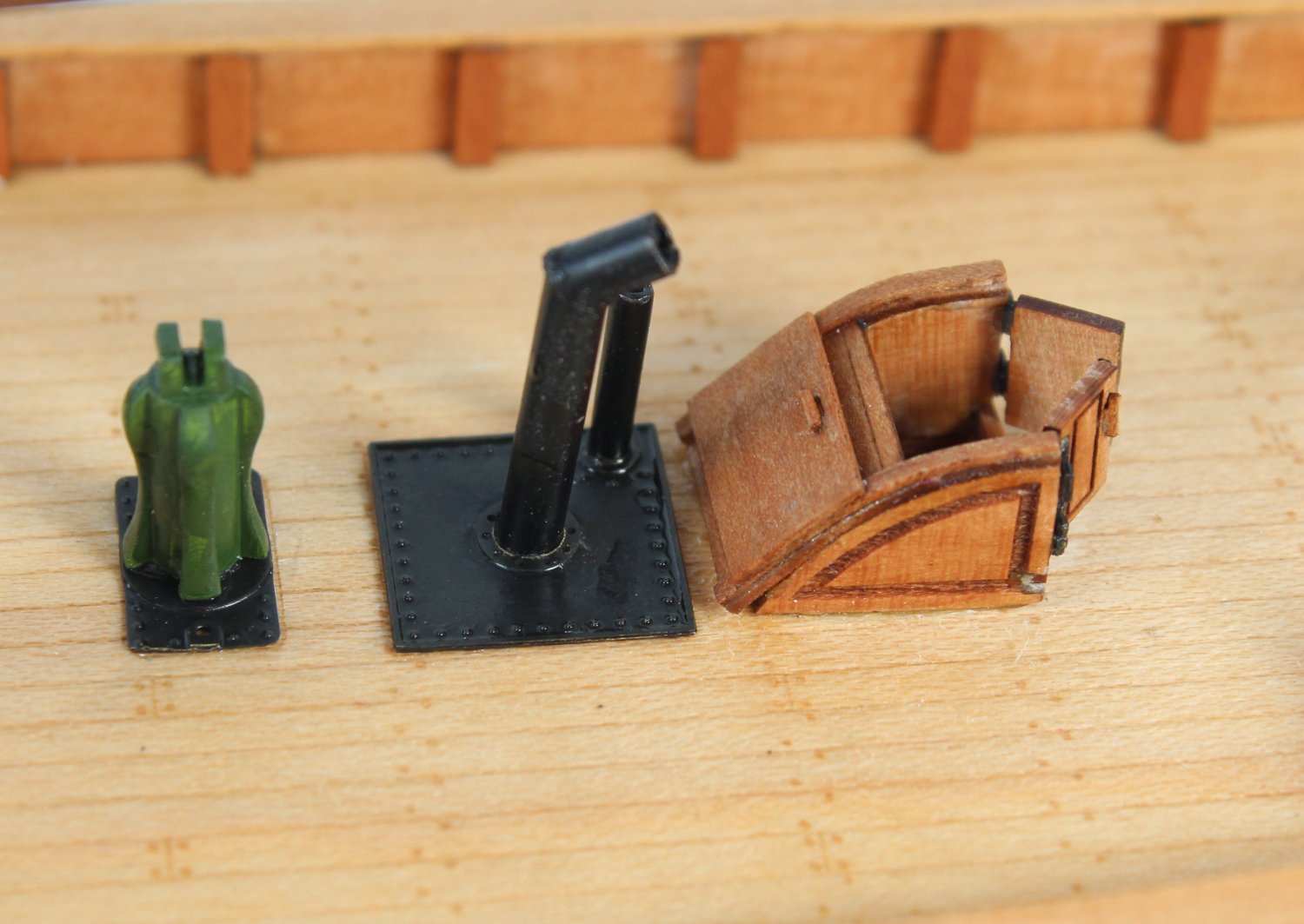
I have also attached some more photos of blocks which I will try to replicate over the next few days.
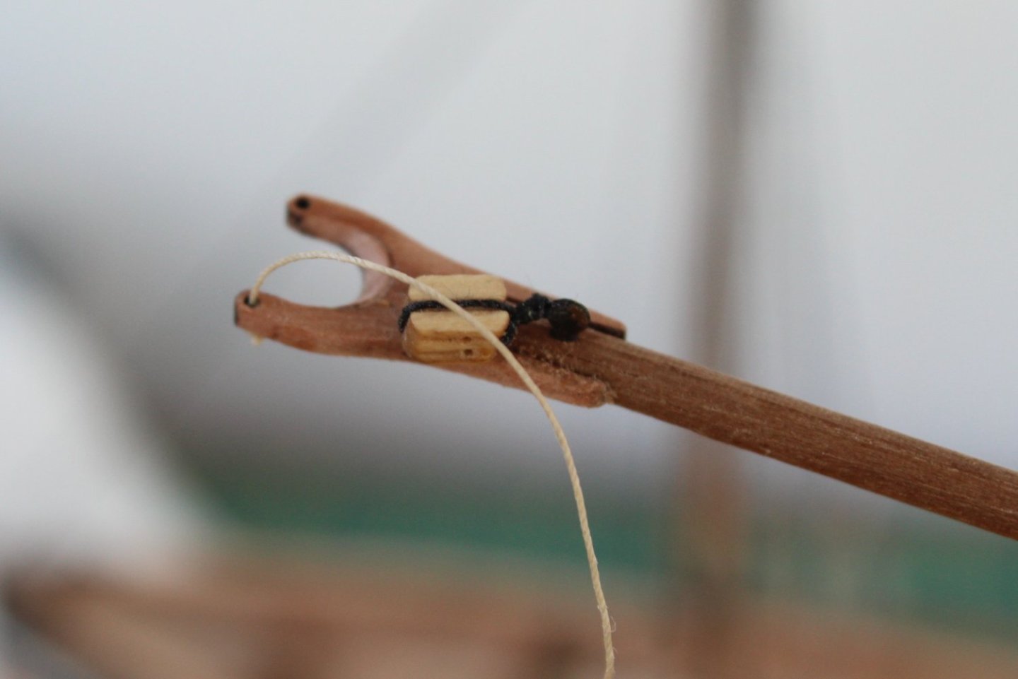
In the next photo the bottom block required a thimble adding to the bottom of the block.

In this photo the bottom block is secured to the hull via an eyebolt arrangement,


-
-
20 minutes ago, Gus Martinez said:
We will be there to follow the evolution of HMS Indefatigable, of course.
I'm still starting, catching up with my Croos section San Francisco, more than anything else to learn, and learn for my mistakes, but I hope in a short time to acquire the Zulu 'Lady Isabella' or the Fifie 'Lady Eleanor', I think they will be ideal to get me started in something more advanced, and this thread teaches many things for it.
The fishing boats from Vanguard Models are a great starting point.
-
6 minutes ago, Gus Martinez said:
Hi Glenn....
I really like this ship, it's beautiful, as you explain its evolution in such a detailed way, I think it's a great thread to see how to make a nice model and learn
thanks for sharing.
I following this thread, of courseMany thanks Gus. I have enjoyed building the 3 small fishing boats, makes a nice break from the more complex builds.
Next up for me will be HMS Indefatigable (Indy) which is due to be released in a couple of weeks. I think this will be a 2 to 3 year labour of love.
- JpR62, chris watton, AJohnson and 1 other
-
4
-
18 minutes ago, chris watton said:
I would be careful if using HMS Trincomalee as she looks today as a reference for Indy detail, Trincomalee is shown as she was in a much later period than Indy, being a very late build Leda Class.
Noted, I have been there a couple of times before and it is a great place to visit. I was not planning as using Trincomalee as a reference for Indy but there are certain aspects which will be of great interest.
- Dave_E, thibaultron, chris watton and 5 others
-
8
-
31 minutes ago, chris watton said:
Manual was completed today (about an hour ago, actually, at the time of writing this), and box art will be complete tomorrow, at which point, all files are sent to printers, so I should have all manual, plans and box labels with me by the end of next week, with orders being shipped week commencing 27th Feb.
All pre ordered kits have a personalised optional name plate included, with the purchasers name.
Great news. I have downloaded the on-line manual and will studying the content so I can plan the build.
I have a trip to visit the HMS Trincomalee tomorrow (14th Feb) at the National Museum of the Royal Navy, Hartlepool. I will be taking plenty of photos which I hope will help me with the Indy build.
-
8 minutes ago, chris watton said:
Well done to Jim, a very long project, and he's done a fine job.
Tomorrow I shall complete the build manual and box label art, and sent to printers as soon as complete.
This has been a very long haul!
Well done to both @James H and @chris watton for an impressive design and build. It is one amazing looking kit and I am really looking forward to the challenge of building the Indy.
- thibaultron, Cathead, Rustyj and 7 others
-
10
-
-
-
-
6 minutes ago, AJohnson said:
Well done Glenn!

Wow one month to build Nisha! Bet Chris is happier with customers of your build rate than mine, he'd be as poor as the proverbial "Church Mouse" otherwise! 🐭
Many thanks. I now have a very nice collection of completed Vanguard Model kits. I would think the Indy build will take me 2 to 3 years to complete so my spend rate with be in recession.
- AJohnson and chris watton
-
2
-
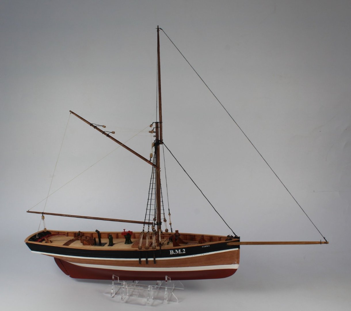
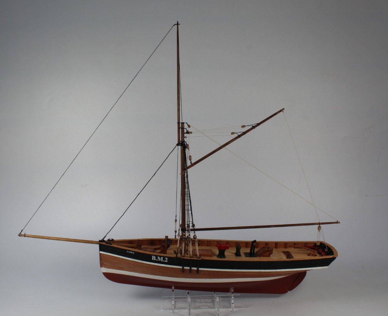
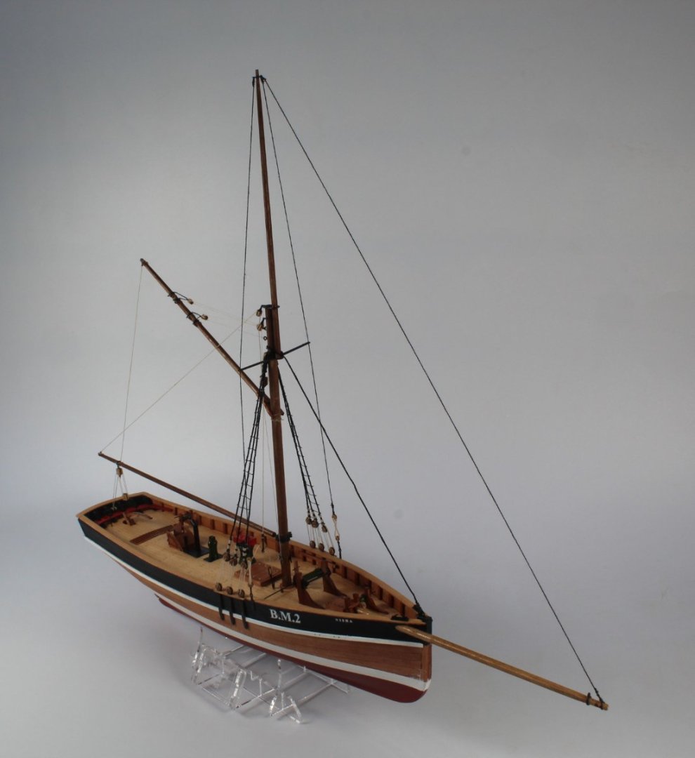
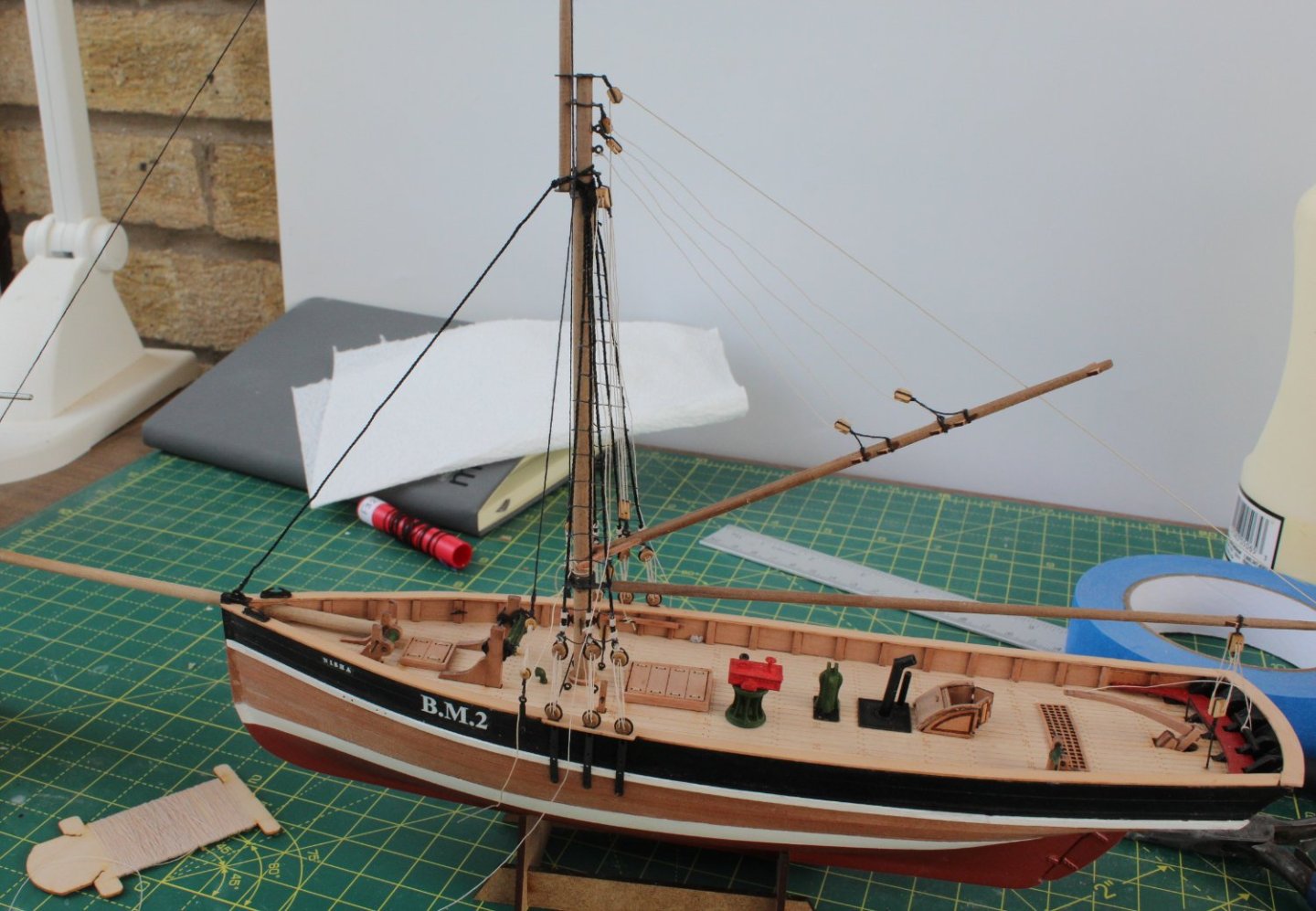
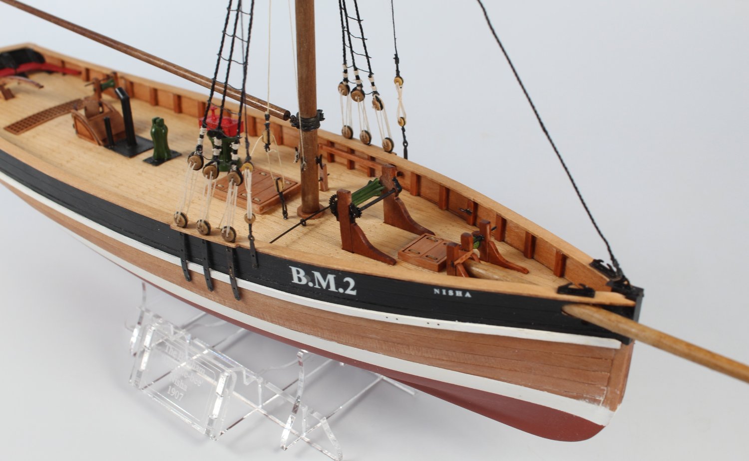
025 - Completed Build
I have completed the build, the final task, after belaying the gaff rigging was to build the display stand.
This has been a interesting build and took me 1 month to build. I have been able to improve on some of my model making skills in readiness for my next project which will be the HMS Indefatigable (Indy) which is has been pre-ordered and the kit is due for release later this month or early March.
Another excellent design by @chris watton and I would highly recommended all of the kits available from Vanguard Models.


- Prowler901, JpR62, ccoyle and 3 others
-
6
-
9 minutes ago, Srenner said:
Have you got your belaying plan clear ? On my jolie brise the running rigging for the gaff needed to be threaded through the same side as the belaying point and through the shrouds.
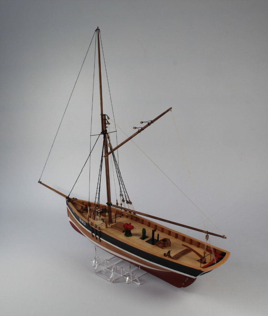
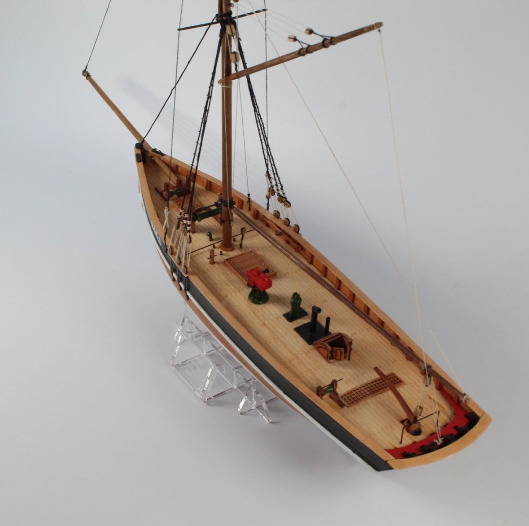
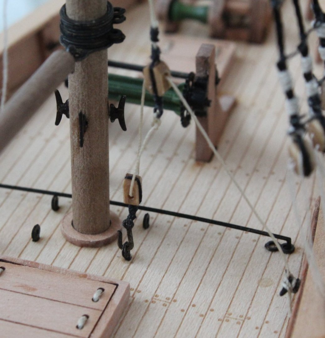
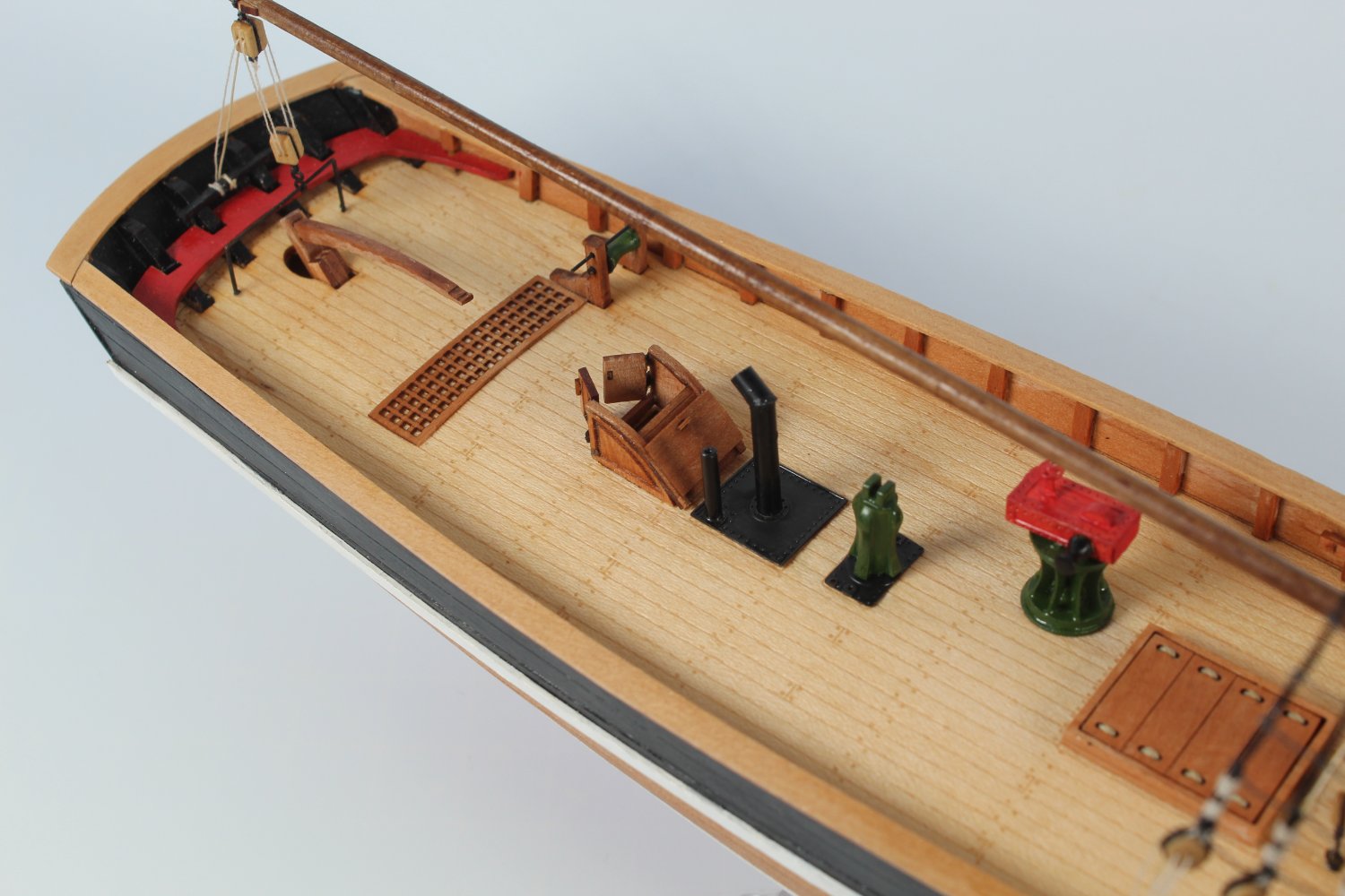
The belaying is very simple. They are belayed to cleats fitted on the main mast as can be seen on the attached photo.
-
024 - Gaff Part 1
It did not take very long to taper a length of 3mm dowel for the gaff, using my proxxon mini lathe. I then added the 10 off cleats and the gaff jaws.
A small hole was drilled in the gaff so the 4mm double block seized to an eyebolt could be inserted for the gaff lift rigging. With the gaff held in my quad hands I then added the two off 3mm single blocks required for the peak halyard rigging.

The blocks were secured to the gaff using clove hitch knots.
The lift 4mm double block.
Using a small length of 0.25mm natural thread through the jaws the gaff was tied to the main mast. The main gaff lift rigging between the two 4mm double blocks was then added.

Finally the rigging for the peak halyards were added.

The various gaff rigging is now installed and the 2 off free ends for the lift and peak halyards are ready to belayed. However I am still undecided how to present the gaff. The normal position for an gaff without the sails would be just above the boom, as shown on the rigging plan sheets. I am more inclined to raise the gaff and rig in the same position as if the sails were fitted as I think this will look better when the completed model is on display. The picture below is sort of a halfway house option, which I am not keen on. I will continue to ponder this overnight before belaying the gaff rigging.
-
023 - Boom
This is a short post as there is not much to detail with regards to fitting the boom
A length of 3mm dowel was tapered down to 2mm using my proxxon mini lathe. The double block was secured to the end using a clove hitch knot. It was then a simple to add the rigging between the double blocks.

A length of thread was then secured to the end of the boom and fed, via a block on the main mast, to a double block arrangement for belaying.

The next task will be to taper a length of 3mm dowel for the gaff.


HMS Indefatigable 1794 by Glenn-UK - Vanguard Models - 1:64
in - Kit build logs for subjects built from 1751 - 1800
Posted
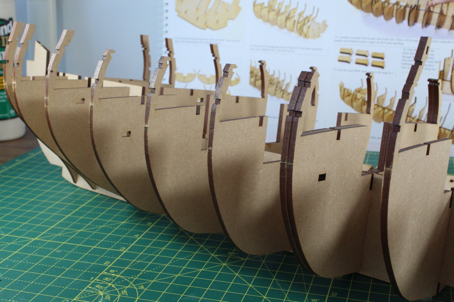
Fitting Bulkhead 1
The various bow filler parts were dry fitted to the bulkhead and a test hull fit was undertaken. Next some guidelines were drawn on the bulkhead in readiness for the pre-fairing, as can seen in the first photo below, using the photo in the build manual as a reference.
Fairing guidelines were also drawn on the filler patterns.
Using a combination of a Ginour rotary tool, sanding sticks and sanding blocks the pre-fairing of the bulkhead was completed.
The completed bulkhead assembly was then added to the keel.
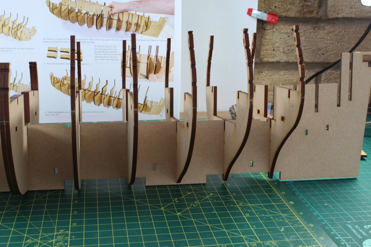
Fitting Bulkhead 18
The various stern filler parts were dry fitted to bulkhead and I started to add some guidelines.
After the filler patterns had been glued in place the pre-fairing of the bulkhead assembly was completed. I generally find the pre-fair of this type of bulkhead assembly much tricker than the bow assembly. I took my time and stopped to check the progress at regular intervals, and also compared with the photos in the build manual.
The final task was to take the 2 off stern patterns, shape and fit. There is quite of bit of sanding required to shape these patterns, I have left of bit of excess material on these patterns which can be removed during the final hull fairing later in the build process. The pattern has not, as yet, been glued to the keel in the photo below.