


Glenn-UK
-
Posts
2,666 -
Joined
-
Last visited
Content Type
Profiles
Forums
Gallery
Events
Posts posted by Glenn-UK
-
-
Today I started work on the Fore Mast. I decided that the first part to work on would shaping the 5mm square section for the crosstrees assembly. I used some ideas I had seen on the "John Build Iconic Models" YouTube channel with regards to marking and removing the excess wood.
With reference to the picture below I started with two lengths of masking tape. Each tape was cut to 26mm which is the approx. diameter of the 8mm dowel. I then added a centre line to the tape and marked 4mm either side of the centre line and 4mm from each edge. The tape was then wrapped around the dowel at the top and bottom edge of the 5mm square area. I then drew lines on the dowel so I had a reasonable guide to how much wood needed to be removed.
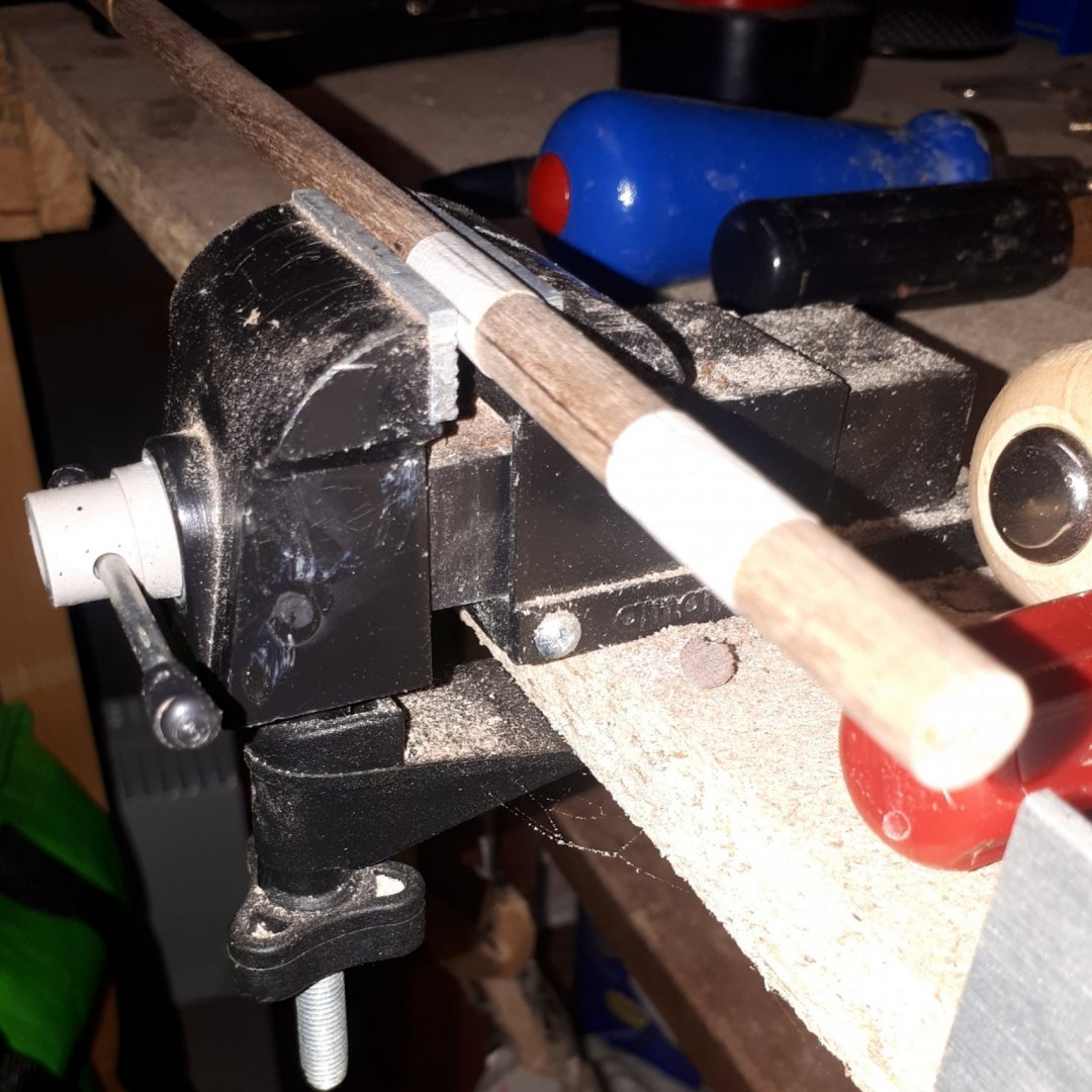
I started by making a cut to the approx. depth at the top and bottom with my saw so I would have a neat edge. Using my sharp craft knife, in conjunction with a sanding stick, I removed the excess wood. I positioned the dowel in my mini vice so that I had to stay above the top of the vice jaws when cutting and sanding. I continued with this process until I was happy I had a 5mm x 5mm square section, as shown in the two pictures below.


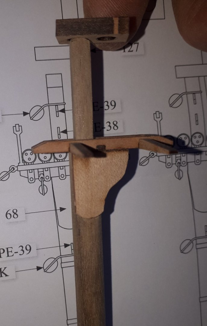
To make the 5mm circle for the end cap I did toy with the idea and using a small section of 5mm dowel and fixing to fore mast with a pin and glue. I rejected this and using my mini lathe with some sandpaper I had soon reduced the dowel to 5mm . I then marked the position of the cheeks, and using my craft knife and sanding stick removed the excess wood. I was reasonable happy with the end result. Once completed I dry fitted the crosstrees, cap and cheeks and I was happy that everything fitted together OK, as shown in the final two pictures.

- egkb, KARAVOKIRIS, JpR62 and 5 others
-
 8
8
-
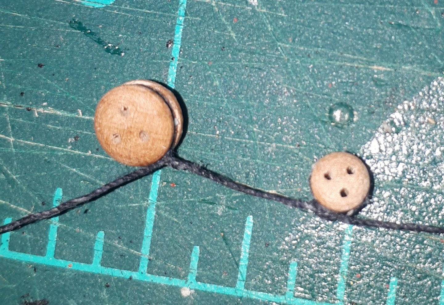
I have had a good morning as I finally completed adding all the blocks and deadeyes to the bowsprit. I thought I would share my method, which may not be the best (or indeed correct) but it worked well for me.
To start with I looked at the requirement, and began to ponder how I could replicate the multiple deadeyes (and blocks). I watched the J Brent YouTube videos a few times for ideas, which I found really helpful and something I will use but it did not really address this requirement as shown in photo below.

I started with cutting a length of thread which I then ran through my beeswax block a few times. After that I positioned the first deadeye in my tweezers and added a touch a ca glue and attached the thread centrally, as shown below.

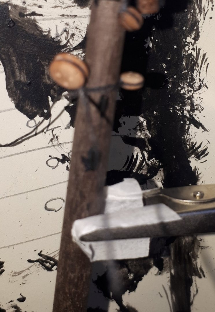
I then wrapped the tread around the deadeye and secured with another touch of ca.
I then added the next deadeye and moved it down the length of the thread to the correct position, checking the position by test wrapping it around the bowsprit, as shown in the pictures below.
The final picture is the completed bowsprit, dry fitted to the hull. I will now start work with making the fore and main masts, yards and booms.
- GrandpaPhil, Edwardkenway, JpR62 and 4 others
-
7
-
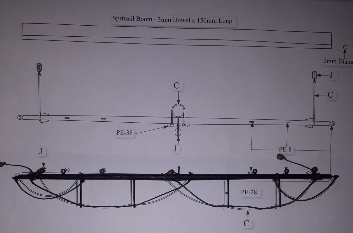
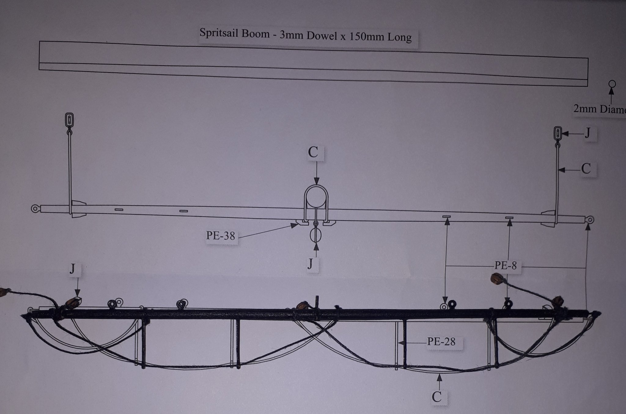
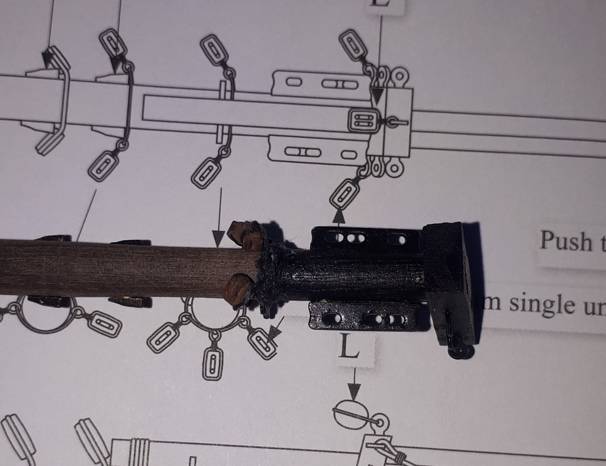
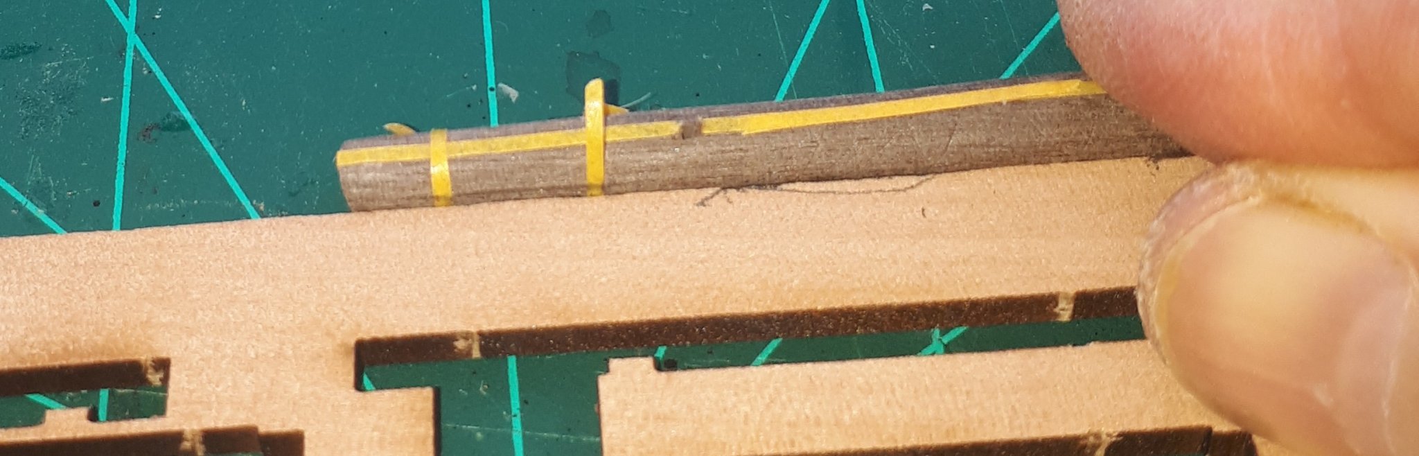
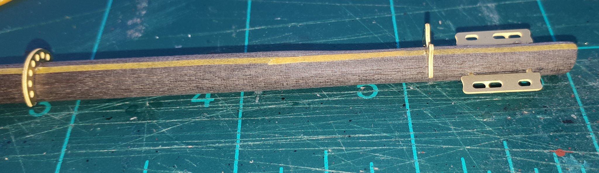
Progress has been slow, partly due to me enjoying the sunshine in the garden and partly due to nature of the current phase of the build.
I have now completed the Spritsail Boom, you will note I have added a pin ready for when spritsail boom is fixed to the bowsprit and a couple of the eyebolts could be better positioned, but it looks Ok to the naked eye.
I have also started to add the blocks and deadeyes to the bowsprit.

- GrandpaPhil, ccoyle, JpR62 and 2 others
-
5
-
Great answer Chris. I will continue to use the kit supplied belaying pins
- Mr Whippy, chris watton and ErnieL
-
3
-
2 minutes ago, Suzdal said:
Glennard
I've been following along your build of the Speedy with a lot of interest while in confinement. Am also interested in tackling the ship.
Forgive me for asking, if you've already answered the question.
What is your mini lath that you're using to tackle the various yards and etc, ... ?
Richard
Hello Richard
I bought the Proxxon DB250 Micro woodturning lathe a few years ago. It seems to do the job Ok.
-
35 minutes ago, NewbyMark said:
I took the alternative view. I could not stand to see them without restraints, so I have ordered the required parts. I also ordered replacement belaying pins because I didn't really like the PE pins (not sure PE is really suitable for these parts). I think they were the only two changes I'd make to the kit though, thoroughly enjoying the experience otherwise. Your build looks great, looking forward to seeing her finished!
I would normally rig the cannons. I was not too sure about the PE belaying pins but will try using them. I do have some wooden belaying pins which I could possible use if necessary.
-
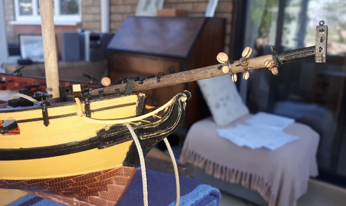
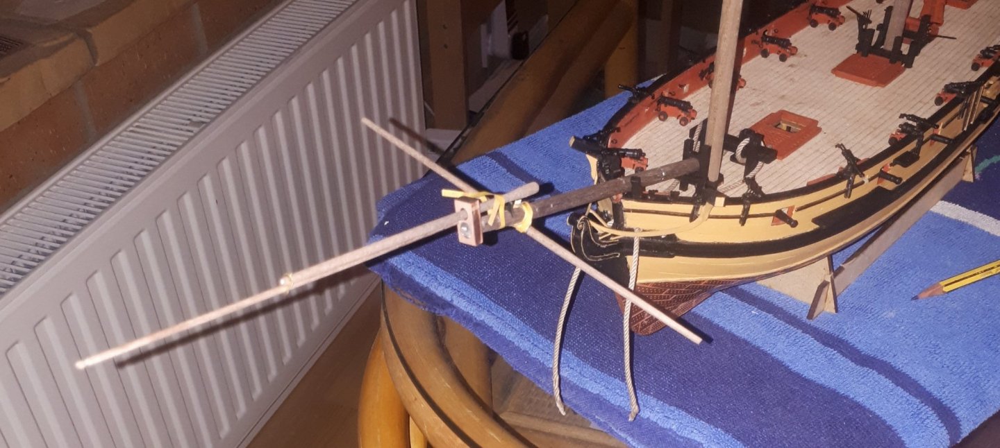
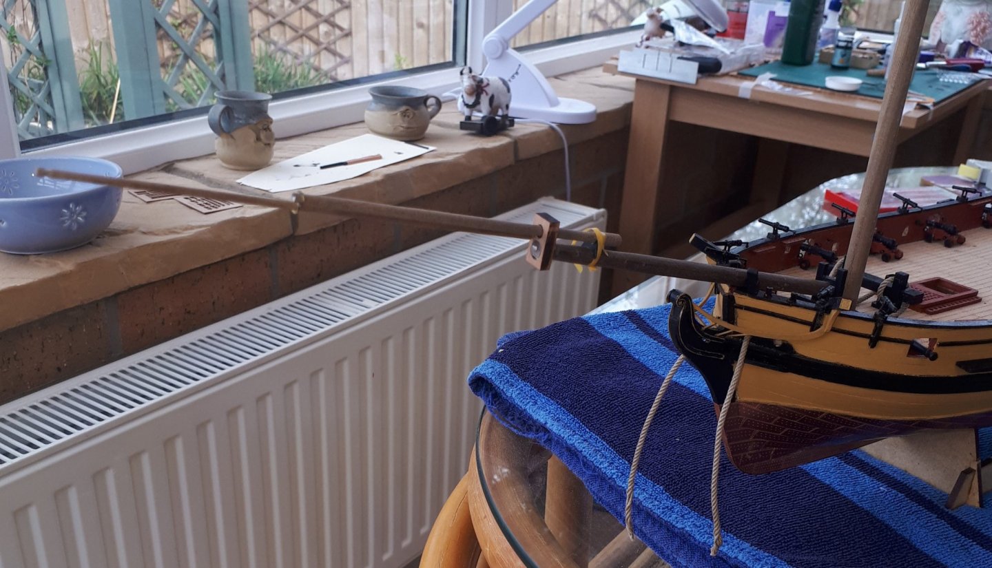
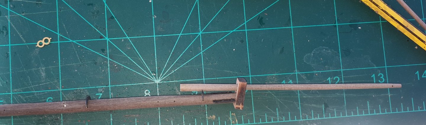
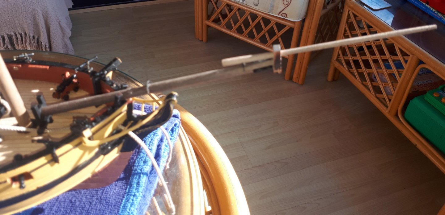
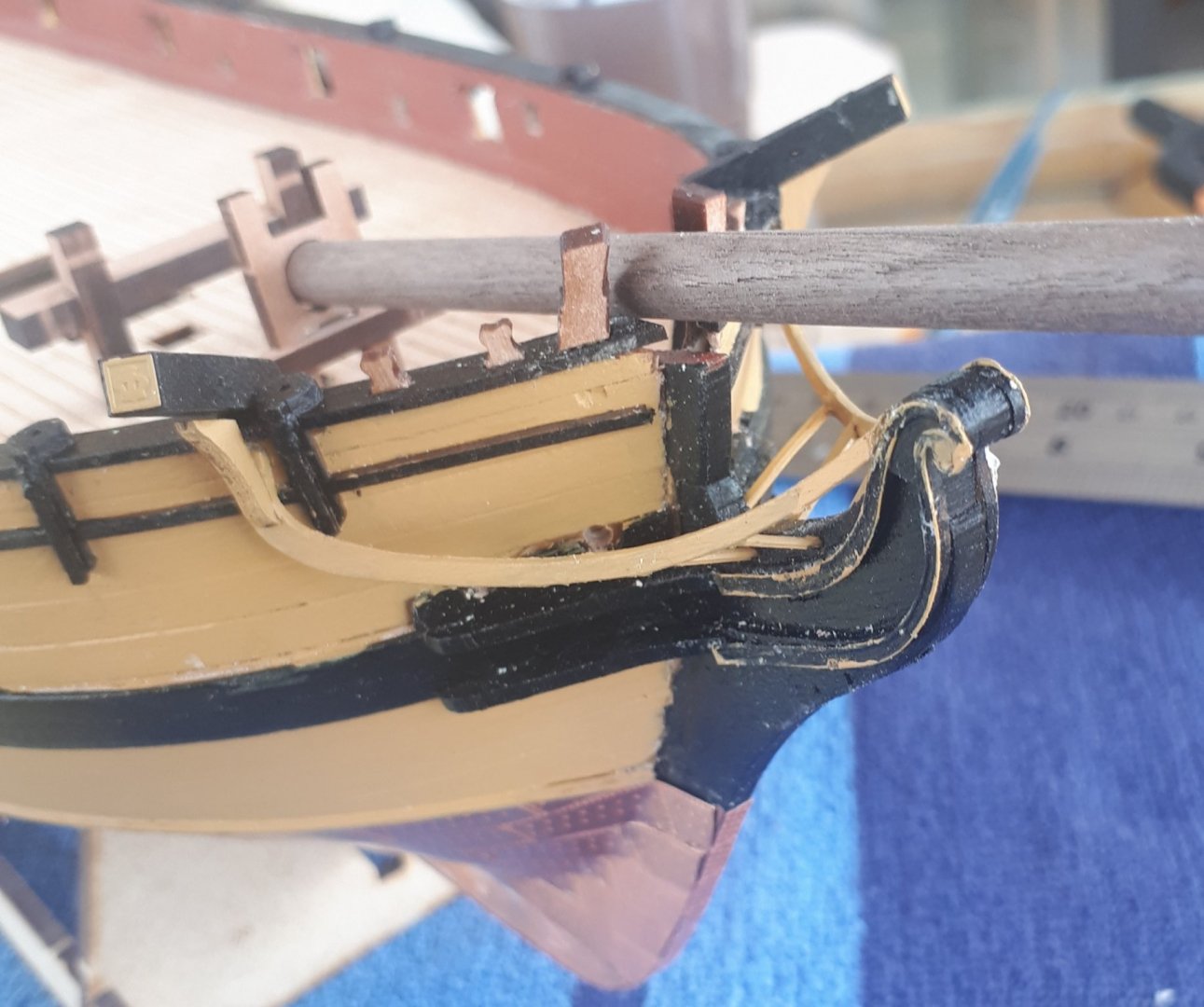
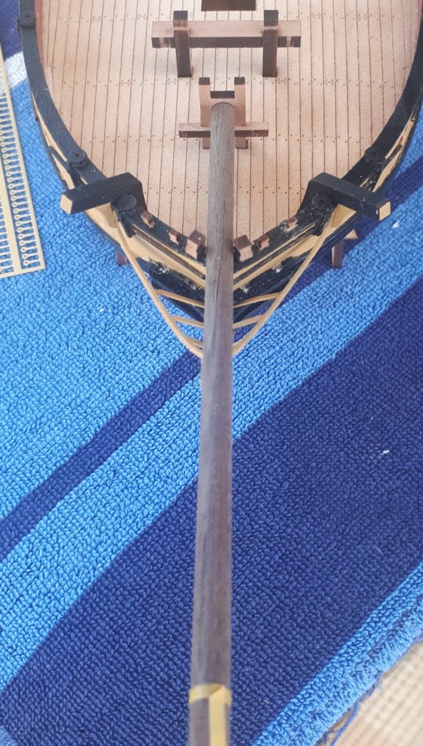
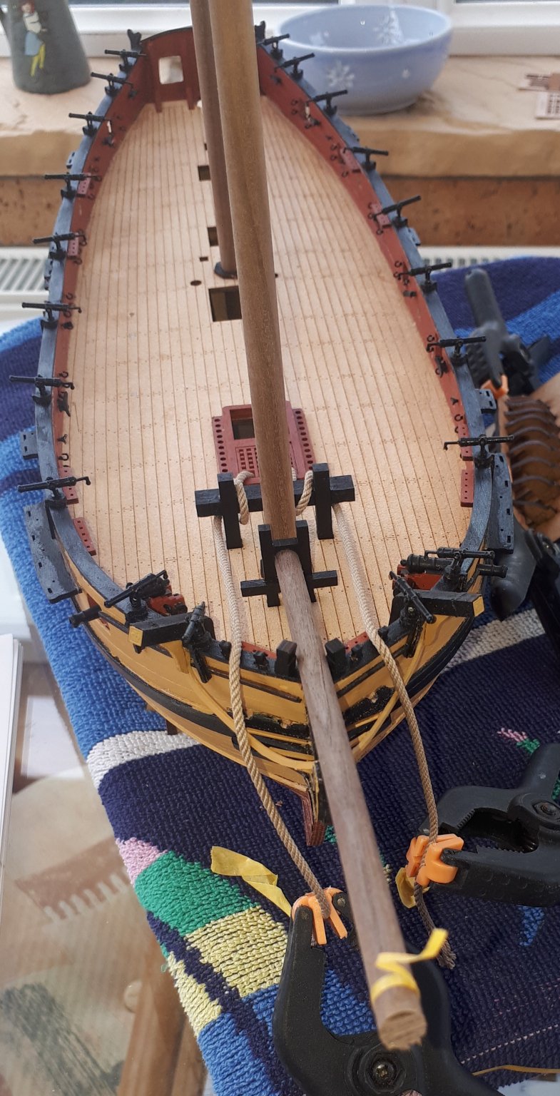
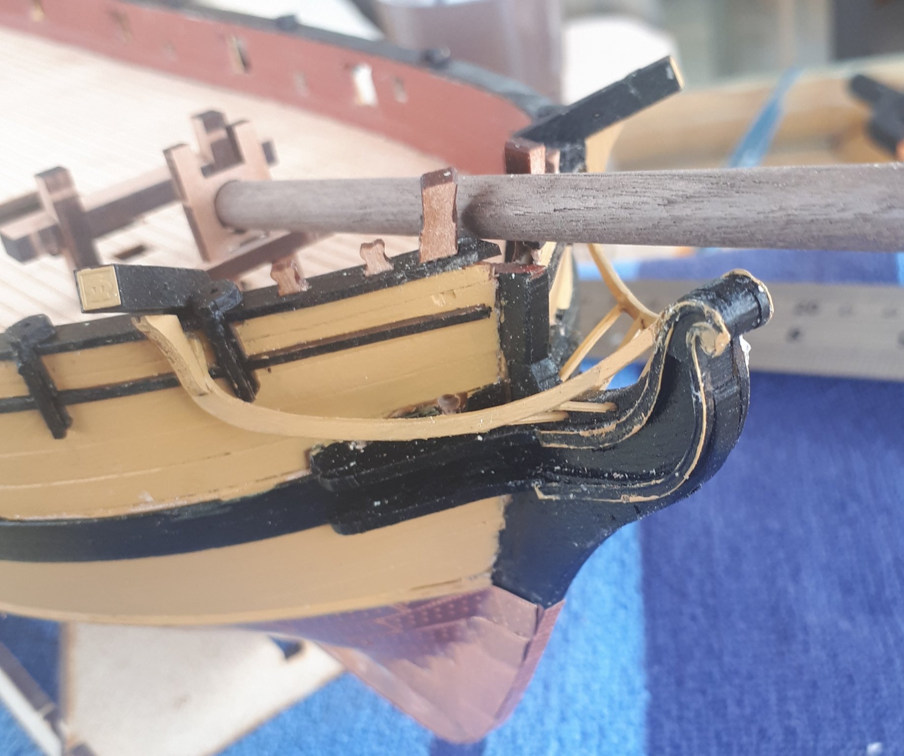
I'm still working on the bowsprit assembly. I have now manufactured the flying jibboon and spritsail. It has been a lot of fun using the mini lathe to get the correct tapering.
The picture below shows the bowsprit, jibboom and flying jibboom dry fitted to the hull. It was a bit difficult to add the spritsail to the dry fit but I did manage to take a picture. I will add the cleats, deadeyes, blocks, eyebolts, etc. to these items before moving on to the manufacture of the fore mast and main mast and their associated yards and spars. I think this will take quite a few days.
With Spritsail
Without Spritsail
- GrandpaPhil, egkb, Edwardkenway and 3 others
-
6
-
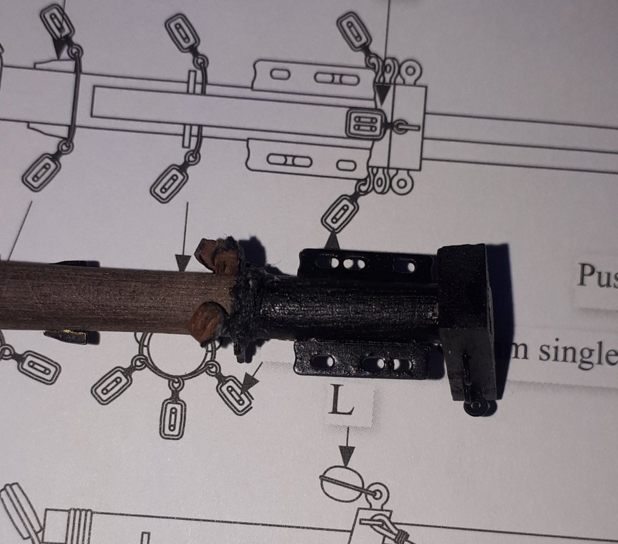
Today I started work in earnest on the bowsprit.
I used my 1mm and 2mm tape to mark the edge and the angle for the cut for the bowsprit cap (part 126) and to indicate the correct positions of the various parts, see the two photos below.
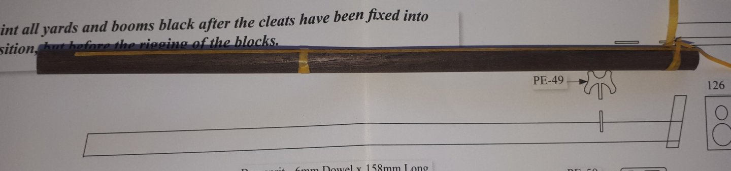
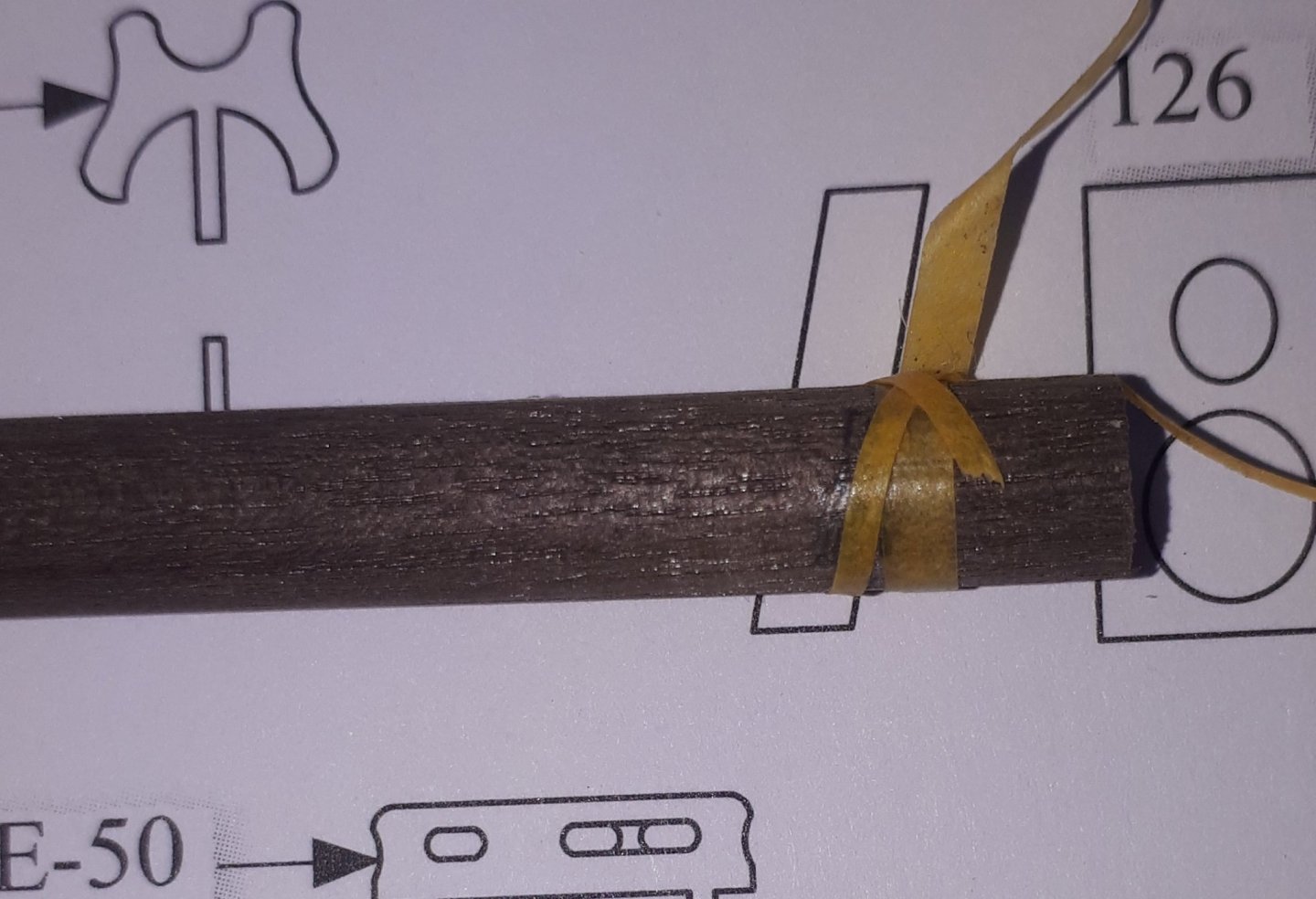
Some items need to be fitted to the side(s). As the material for the bowsprit is a 6mm dowel I used a 3mm wide piece of wood to mark the correct position as shown in the photo below which was taken when marking the position of the bowsprit bees. The break in the tap edge tape is the 0.8mm hole I had drilled for the jibboom saddle.

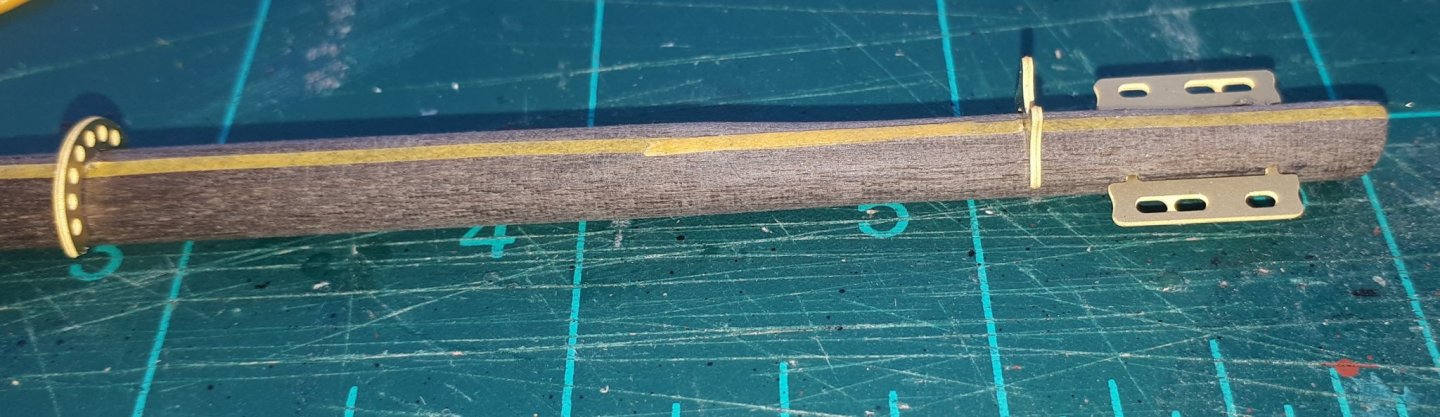
The photo below shows the test fitting of the 2 off bowsprit bee's, jibboom saddle and bowsprit fairlead cleat. The parts were then removed and painted black. I have also drilled the holes for (and painted black) the 11 off bowsprit cleats. The bowsprit was tapered (using my mini lathe) so the bowsprit cap would fit.
I have also started work on the jibboom. I started by drilling the 0.8mm hole and then tapering the jibboon (using my mini lathe) so the bowsprit cap and jibboom and flying jibboom bracket will fit.
The final photo show the bowsprit and jibboom dry fitted to the boat.
- JpR62, KARAVOKIRIS, Edwardkenway and 3 others
-
6
-
I have rigged cannons before, however this kit dies not include the parts for this task. Also I decided that once Speedy has been rigged the lack of rigging on the 4lb cannons would not overly distract from the final build. I would have probably rigged the cannons if I could have done them "off deck" using a cannon rigging jig, which I used in a previous build. This was not going to be possible as I had already glued in the eyebolts to the cannon assemblies.
- Edwardkenway and VTHokiEE
-
2
-
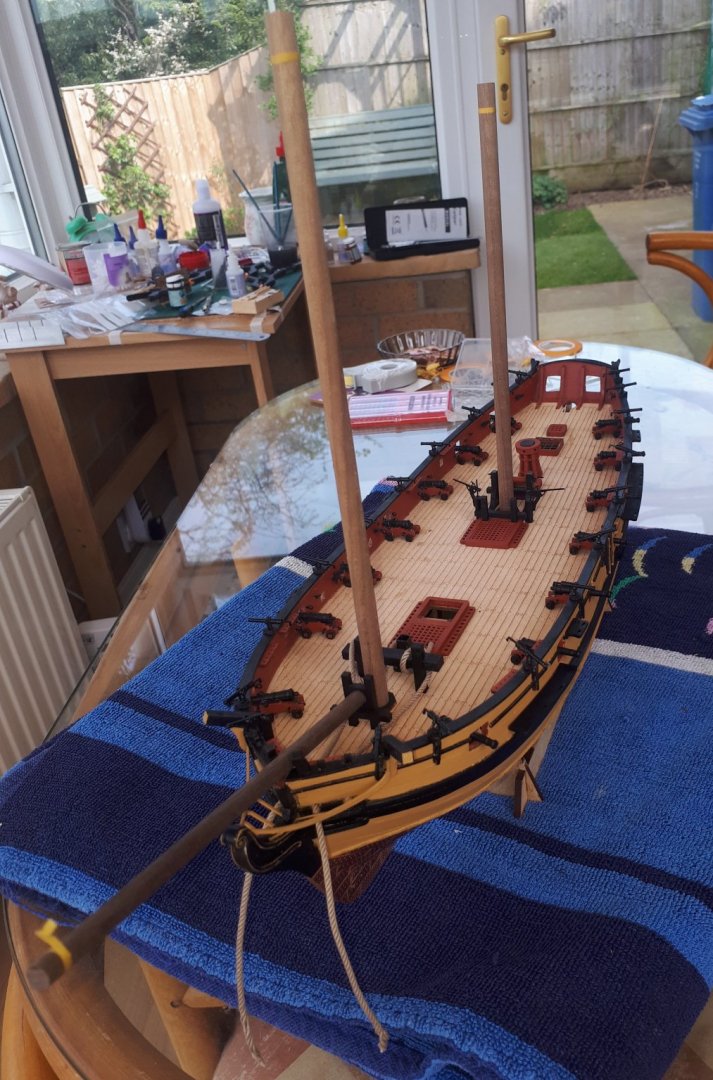
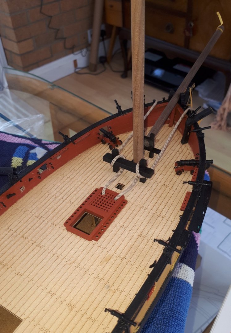
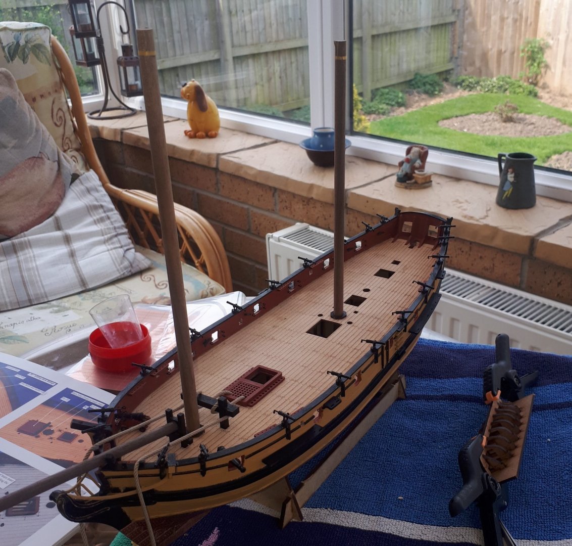
Speedy has now come to life now that all the deck fitting have been fitted. After much inner discussions I have decided not to rig the 4lb cannons.
Next stage will be the production of the all masts. bowsprit, yards, etc.
-
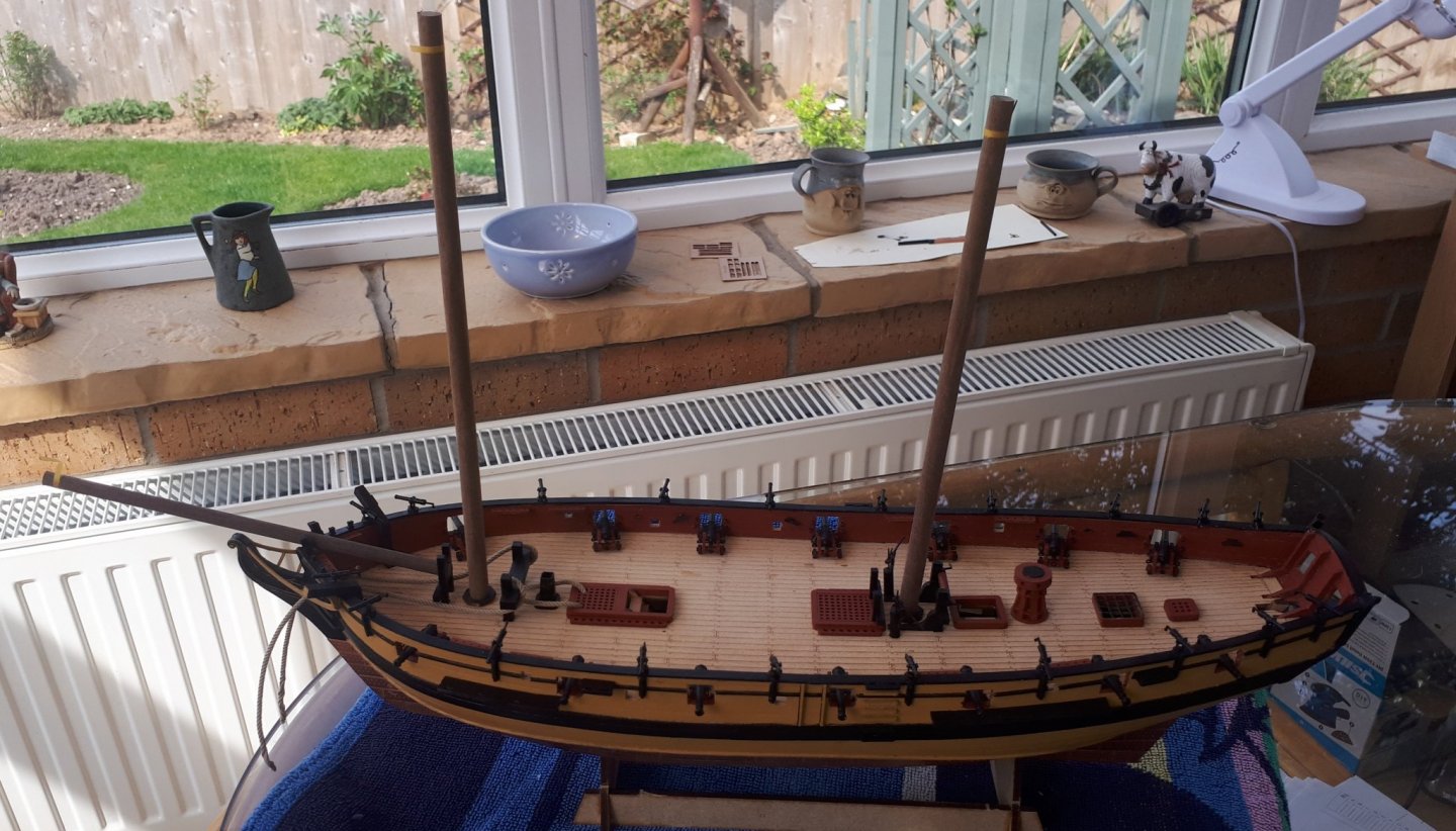
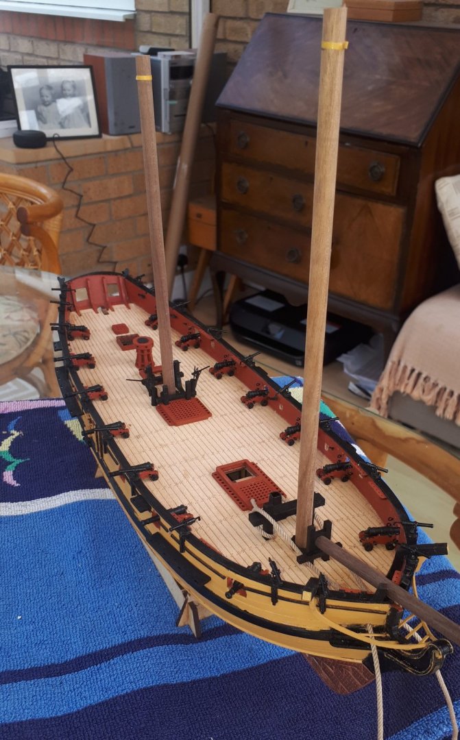
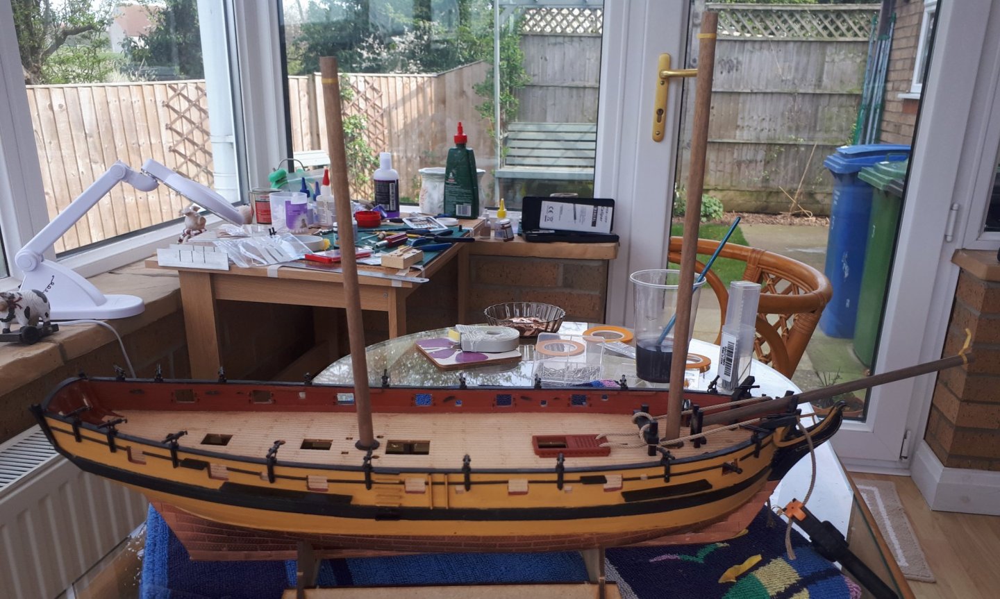
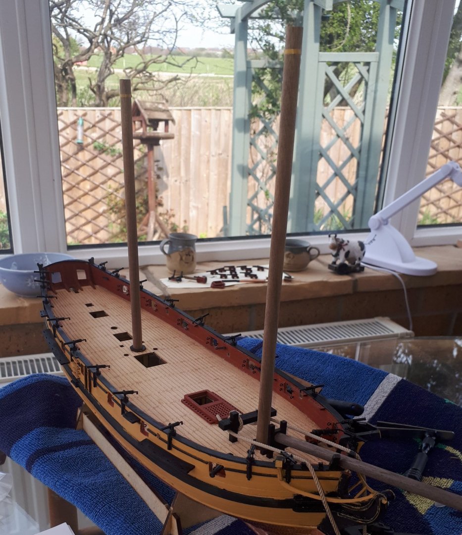
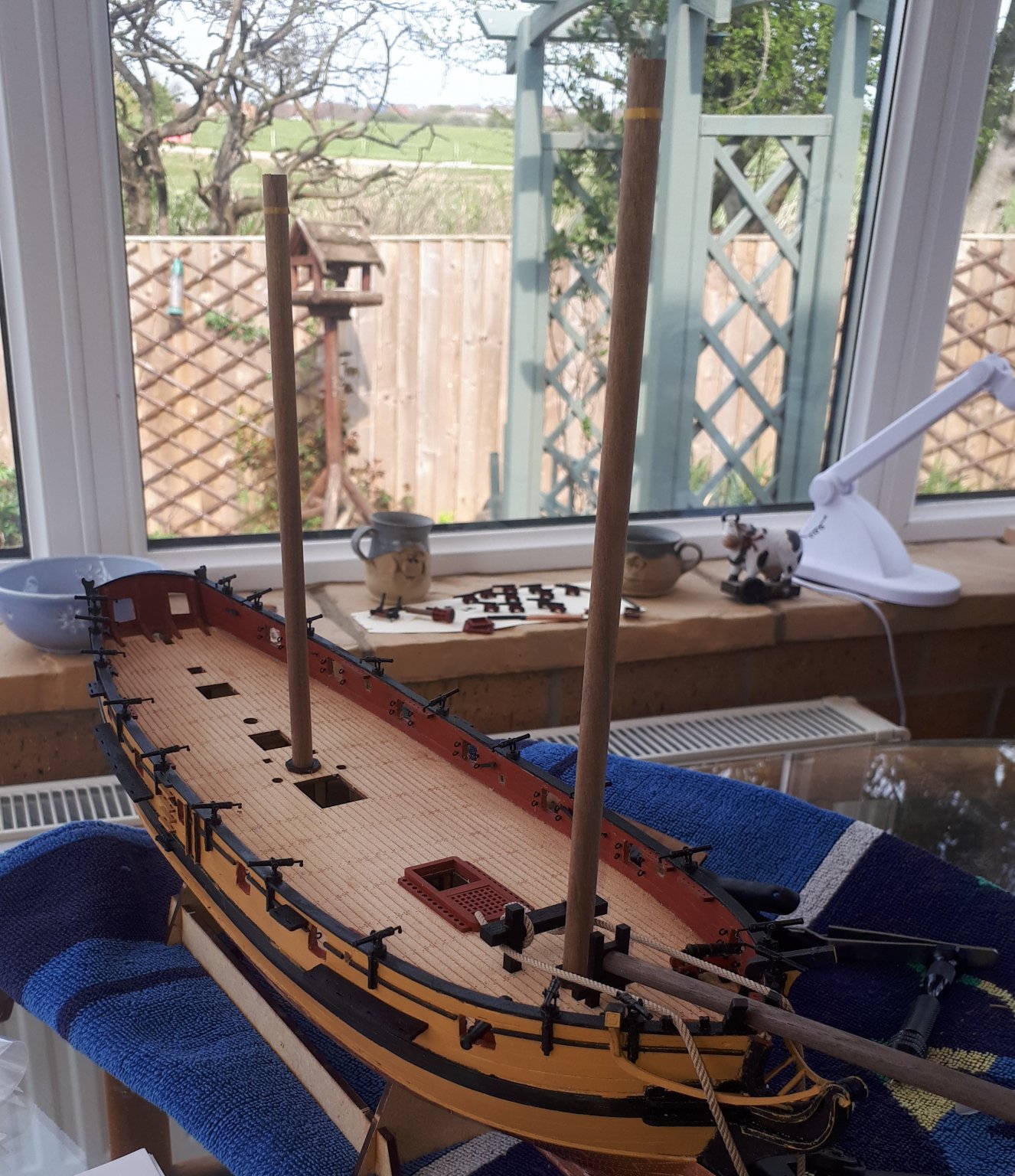
I have painted and fitted the swivel guns (all twenty) and I have started to add all the deck fittings.
I have dry fitted the bowsprit, fore mast and main mast, all cut on the long side. The yellow tape indicates the true length of these items.

- Sjors, chris watton, egkb and 6 others
-
9
-
-
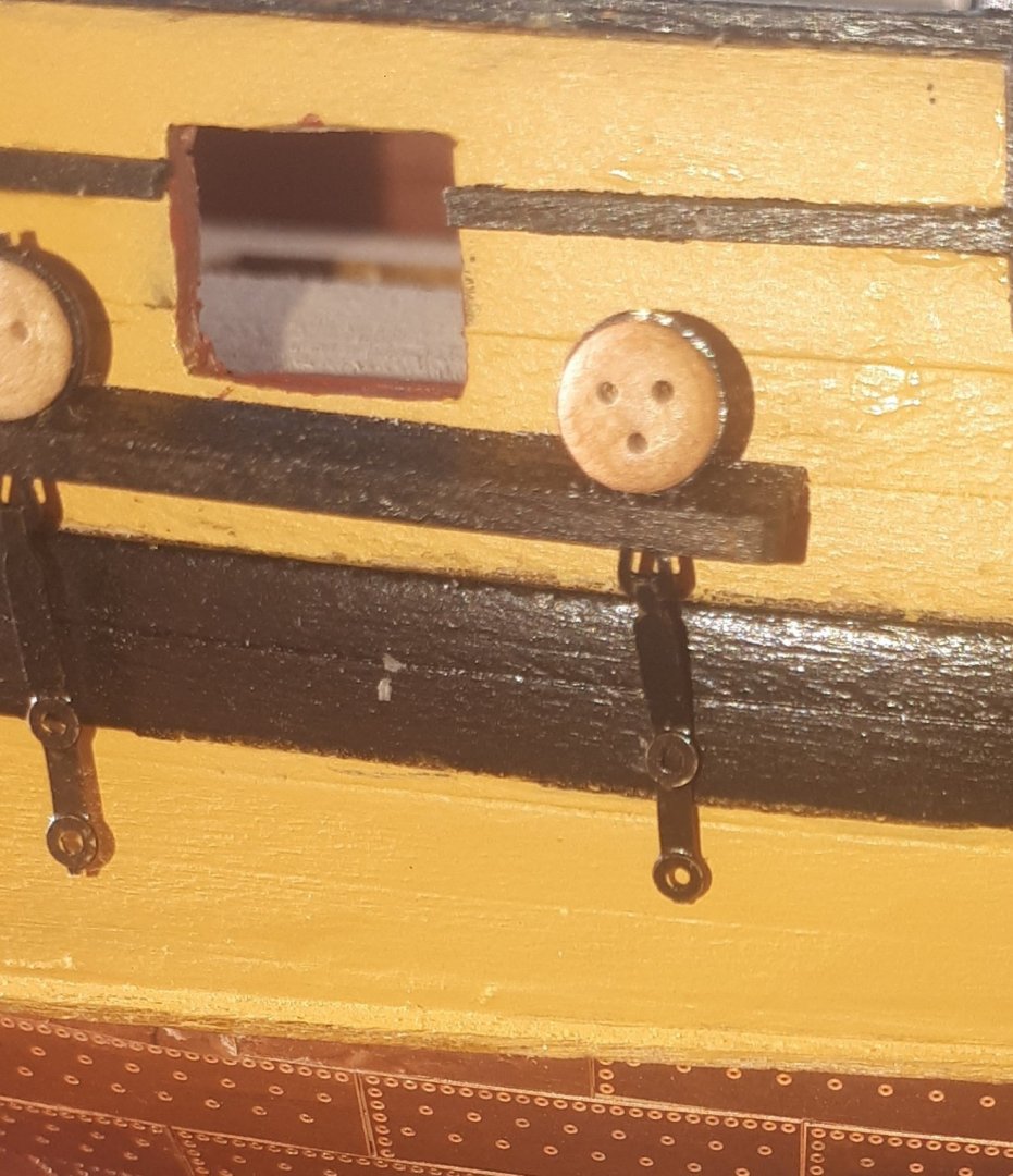
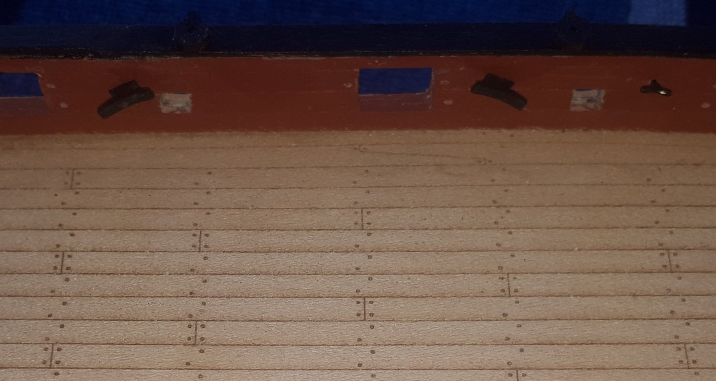
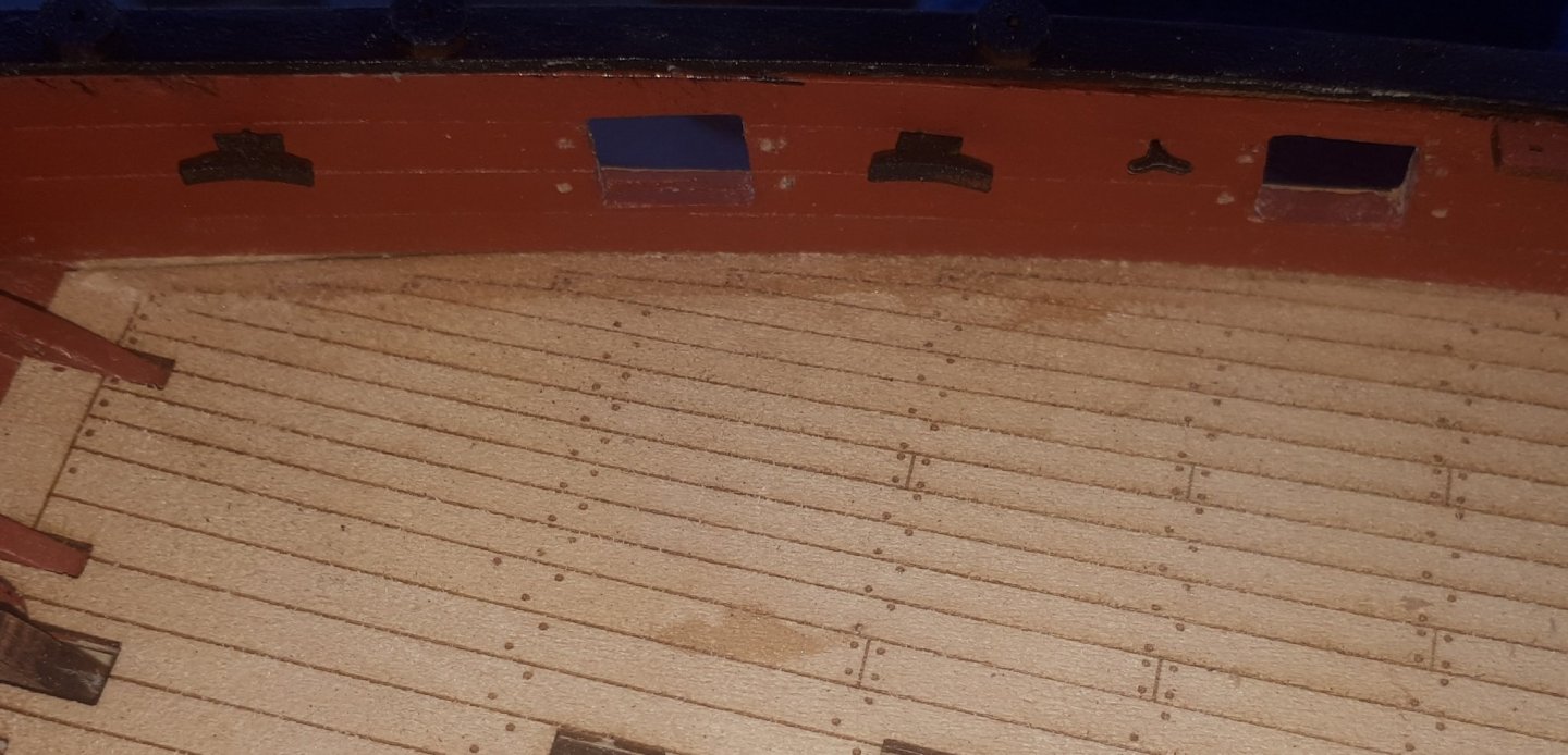
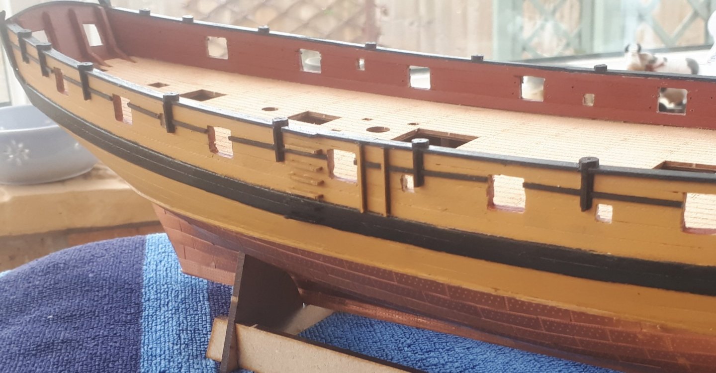
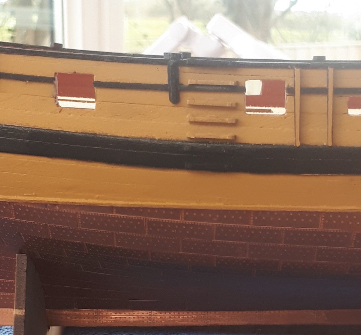
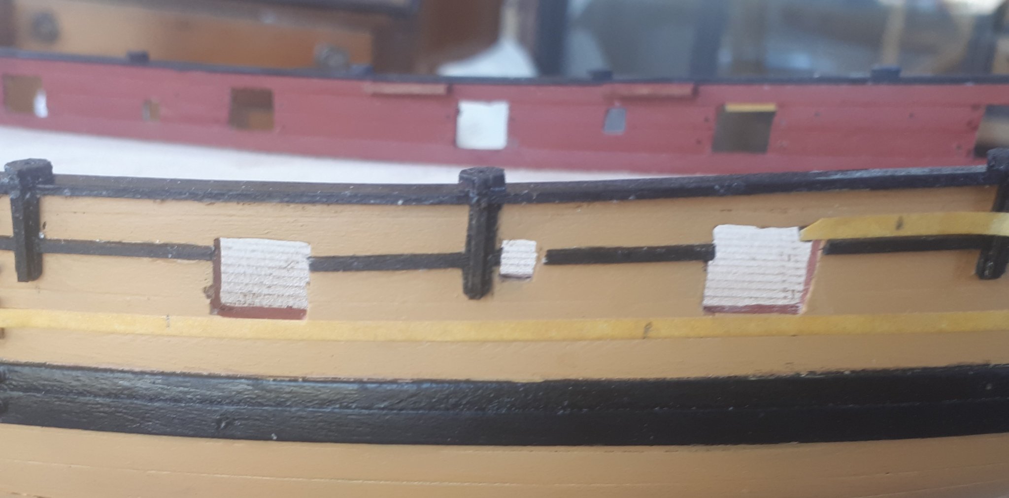
I have now dry fitted the chain plates with the channels. According to the plan sheets the lower end of the 5mm deadeye chain plates should terminate at the lower edge of the wale. It would seem they actually terminate just below the lower edge of the wale. From what I can see from the build photos in the manual the chain plates do terminate below the bottom edge of the wales.
It is possible to ensure that the chain plates terminate with the lower wale edge, noting the deadeye would be slightly raised above the channel.
After Post Comment
After looking at the bending and shaping of the lower part of the chain plate and noting the channel can be raised up a tad as the top edge needs to be level with the lower edge of the gun port (the are only dry fitted at the moment) I have decided to locate the top chain plate pin hole in the wale and to locate the lower chain plate pin hole below the wale.
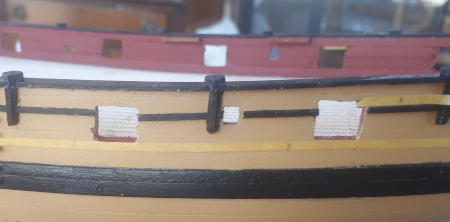
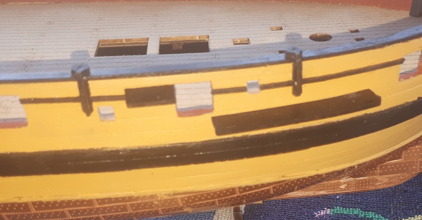
The two photos below shows the channel can be repositioned a tad and also the shaping and current position of one of the chain plates.
- Edwardkenway, KARAVOKIRIS, DelF and 4 others
-
7
-
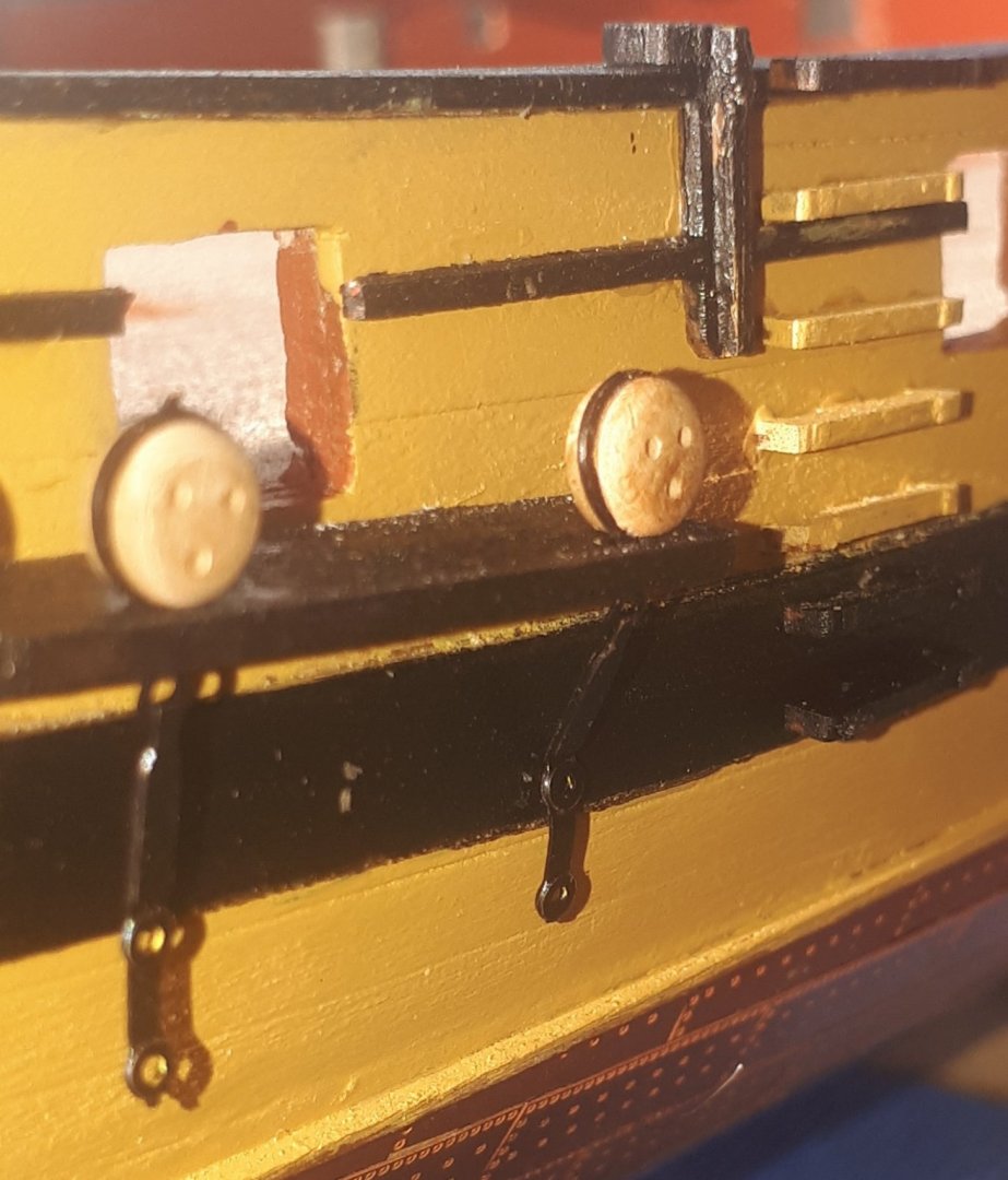
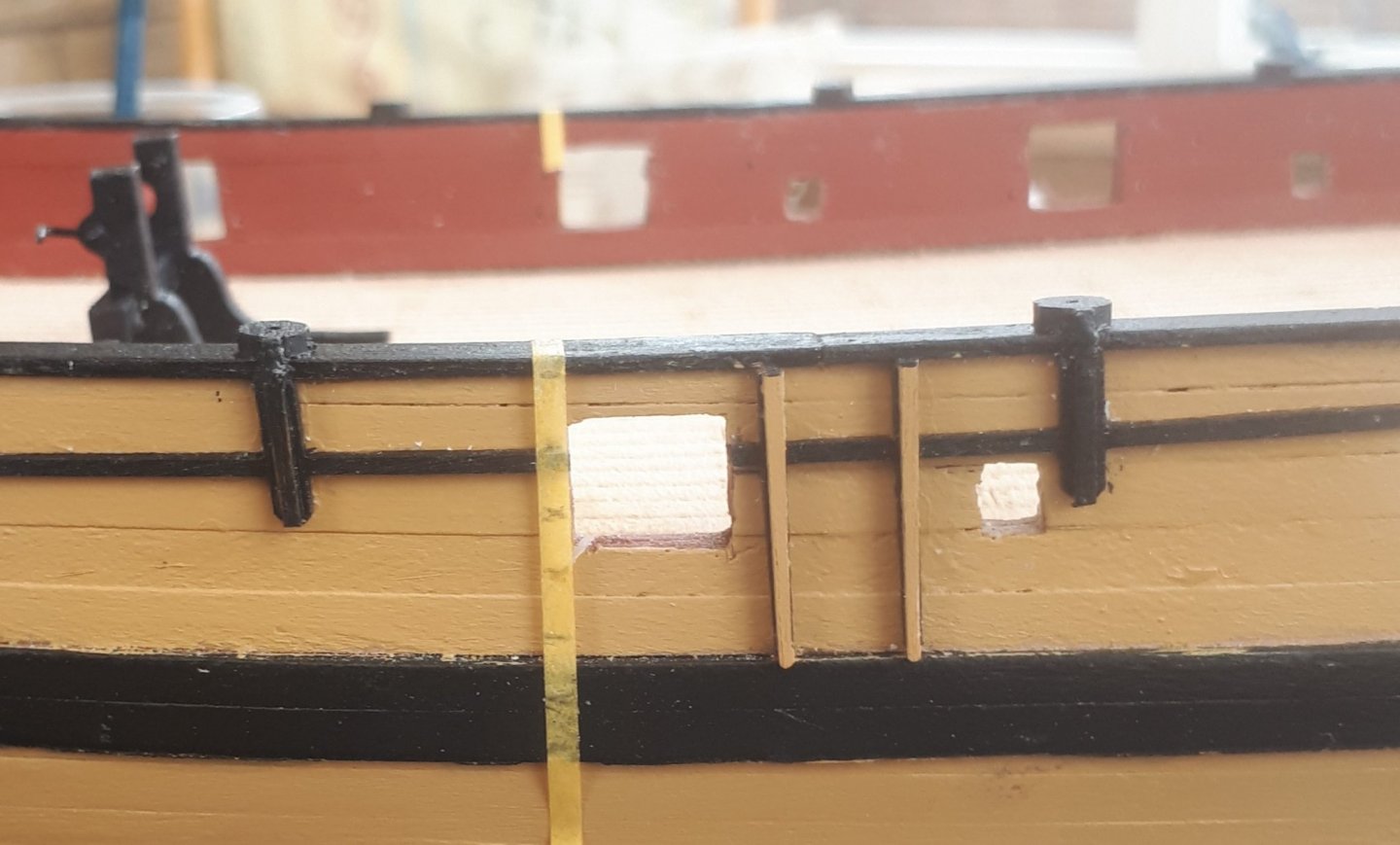
The pins have now been glued in the channels and cleats. I then dry fitted the cleats to ensure the support pins had been trimmed to the right length.
To ensure the channels are correctly positioned and so that I drill the holes accurately on the hull to accept the support pins I used my 2mm tape. I positioned lengths of tape in the correct position for the channels based plan sheet 4 along the hull. I then offered up each channel to the tape (at 90 degrees) and marked the position of the support pins on to the tape. Once I was happy the markings on the tape were in the correct position I used my 0.6mm drill to make the holes for the channel support pins. See pictures below (not great quality)
Cleats dry fitted
Taping of channel positions and marking of the support pin locations.
Dry fitting of the channels to check the pin holes are deep enough.
- DelF, chris watton, KARAVOKIRIS and 5 others
-
8
-
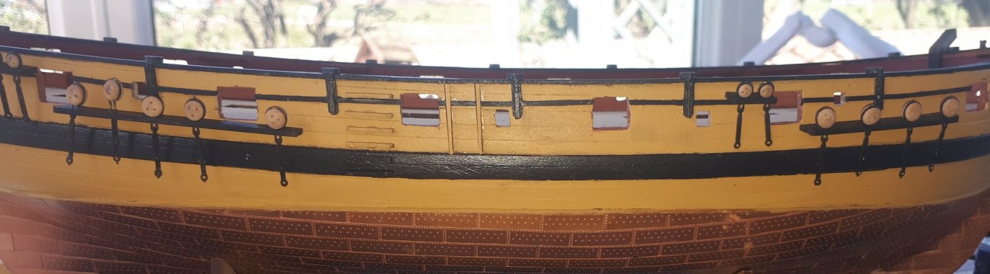
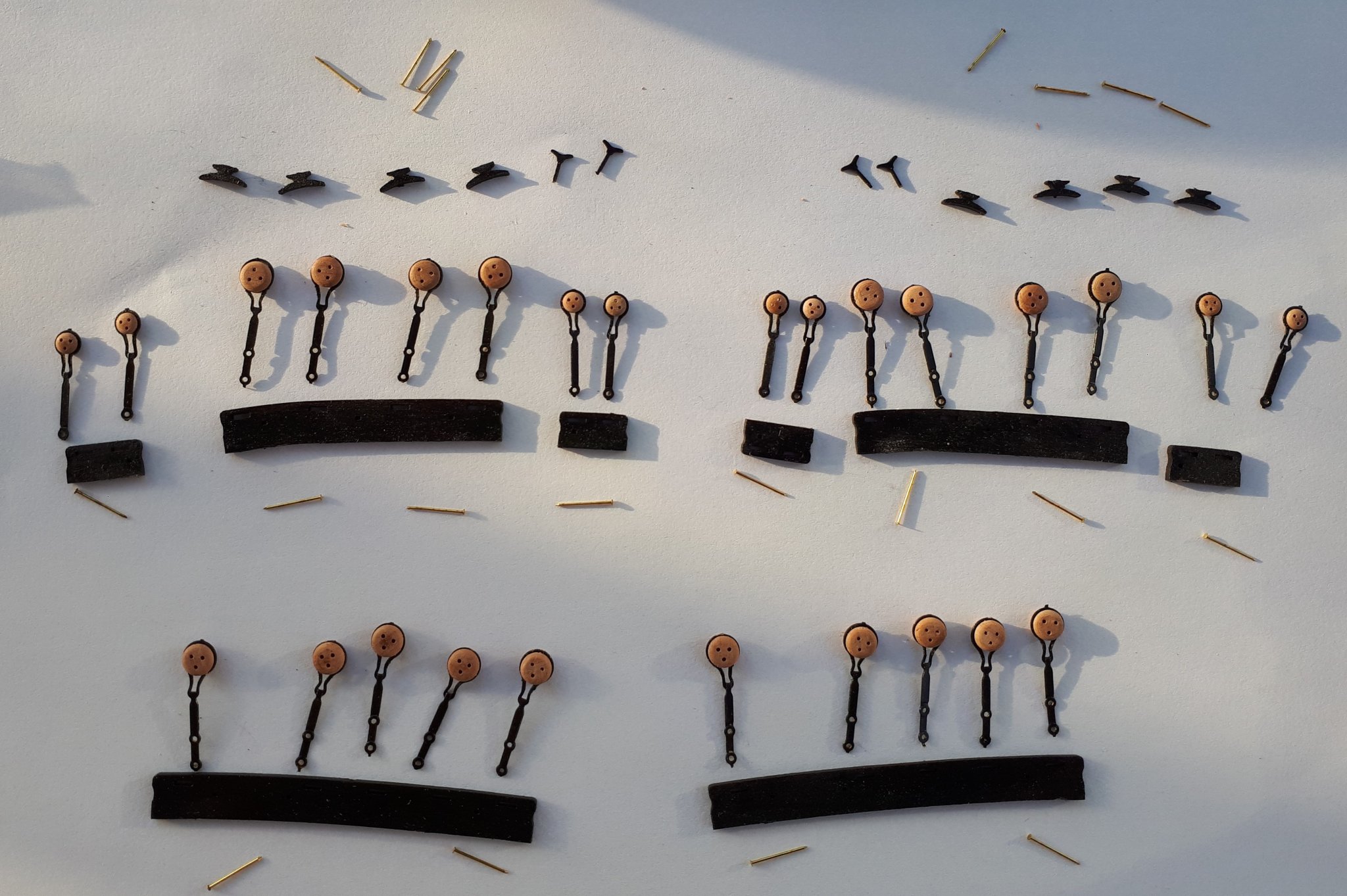
I have now painted the channels and cleats. They have all be drilled (using a 0.6mm drill) so the pins for additional support when fixing these items to the hull can be glued in place. It should be noted that only 6 off (3 per side) of the larger cleats are provided with the kit which is in line with the instruction manual requirements. I will fit 4 per side however, as indicated on plan sheet 4, as I did have some spares.
I have also fitted the 3mm and 5mm deadeyes to their respective chain plates. It did not take to much effort to open up the chain plates to accept the deadeyes and then to close them back up again. The deadeye can still be rotated to ensure they are in the correct position when the rigging stage commences. I may add a touch a ca in advance to help secure the deadeyes in the correct alignment.
I did drop one 3mm deadeye on the floor and despite my best efforts it is now deemed to be "MIA"

- ccoyle, Richard44, KARAVOKIRIS and 5 others
-
8
-
Hello Chris
I have a clarification with regards to the Speedy build related to parts PE 7 (cannon eyebolt) and PE7a (cannon eyebolt ring). I believe correct fitting of the cannon eyebolt ring is as shown in photo (page 34 of the instruction manual), i.e. they are simply fitted over the cannon eyebolts so the eyebolt ring can then be used if the cannons are rigged. Is this correct?
The diagrams shown on page 35 of the manual initially made me think that the eyebolt rings were actually fitted to the hull (as decoration), which I do not believe is the case, the diagram is just simply showing the eyebolt rings in place fitted over the eyebolts, as per the photo on the previous page. I thought it better to clarify as these parts are currently being painted so I can fit to the hull in the next day or two. I have made a few mistakes along the way and I would like to make sure I get this part of the build right first time.
Many thanks for a great kit, I am really enjoying building it at the moment.
-
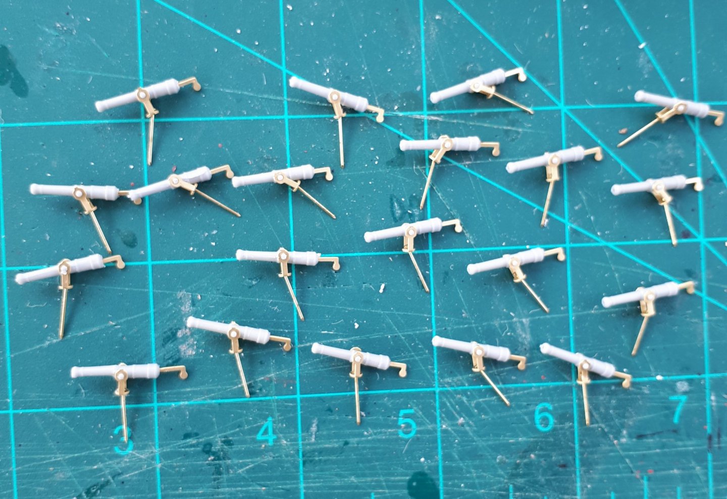
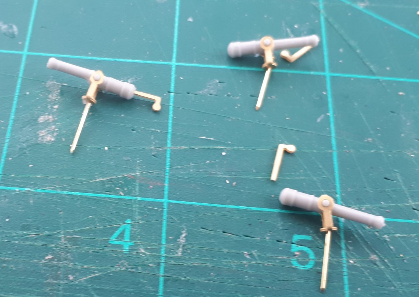
A little pit more progress today.
I have used a 0.8mm drill on the 20 off swivel guns and clued the swivel gun handles into position. I will delay fixing these gun assemblies to the build until I'm ready to finalise the fitting of all the deck items.
I have also fitted the belaying pin racks to the hull assembly. I did follow the advise the manual and used a pin to provide additional support. I'm planning to build and fit the channel assemblies next together with the gun tackle eyebolts and cleats.
- egkb, KARAVOKIRIS, GrandpaPhil and 2 others
-
5
-
5 hours ago, DelF said:
Hi Glenn
Apologies if you’ve mentioned this and I’ve missed it, but have you applied a finish to your copper, or do you plan to? I see some people use varnish or lacquer whilst others prefer the copper to tarnish naturally. What’s your preference?
Derek
Hello Derek
I prefer to apply a clear matt varnish finish to my copper plating.
-
Hi David
Great to hear from you again. I have been away from model boat building for a couple of years (or more). I was really excited by the Chris Watton design and as I was move my work area in to my conservatory (from the garage) I took the plunge. It is a great kit and I really happy to be back building.
I look forward to watching you progress with Diana.
-
9 minutes ago, DelF said:
More great progress. Will you mount all the swivels? I recall Chris saying that would have been unlikely on the real ship, but on the other hand it might seem a shame to leave any off.
Derek
I plan to fit all the swivel guns. I also read that they may not have all been fitted but I think it will look more impressive with all guns and cannons fitted. I also thinking about rigging all (or some of) the 4lb cannons. If I do so I will build a rigging jig to make the task easier.
- chris watton, DelF and Shipyard sid
-
3
-
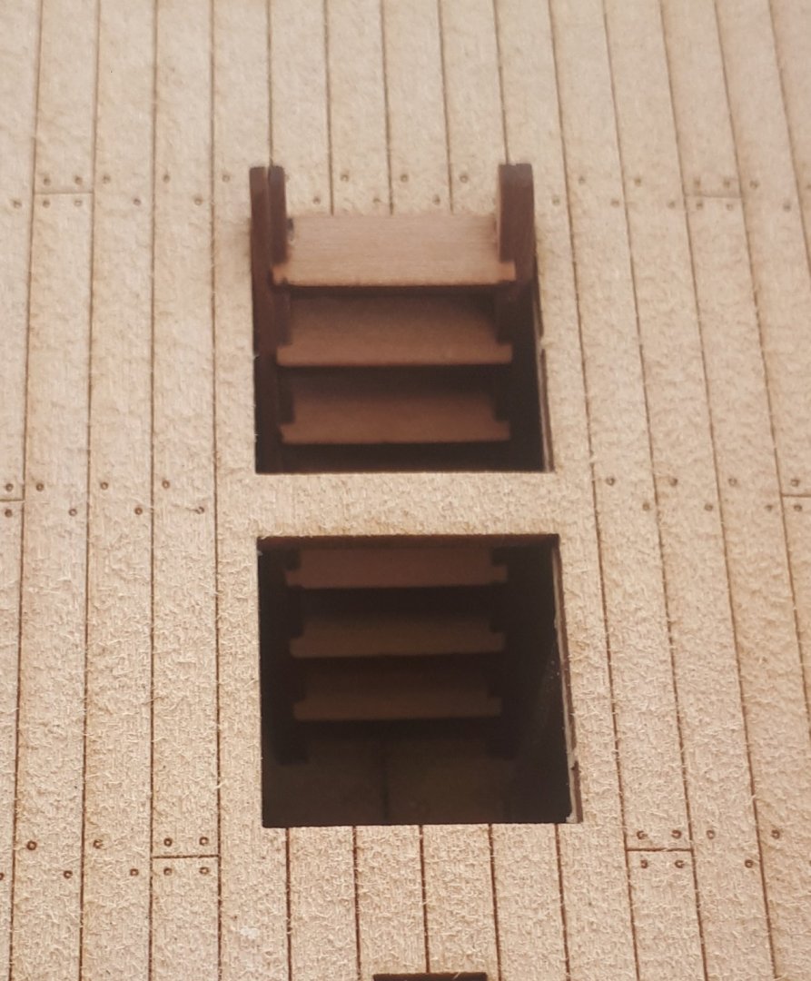
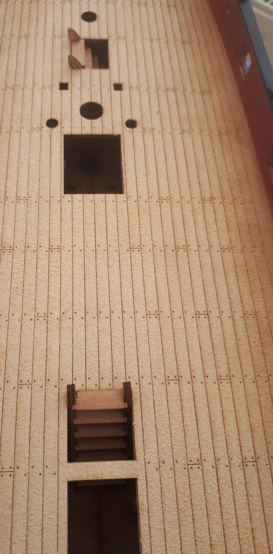
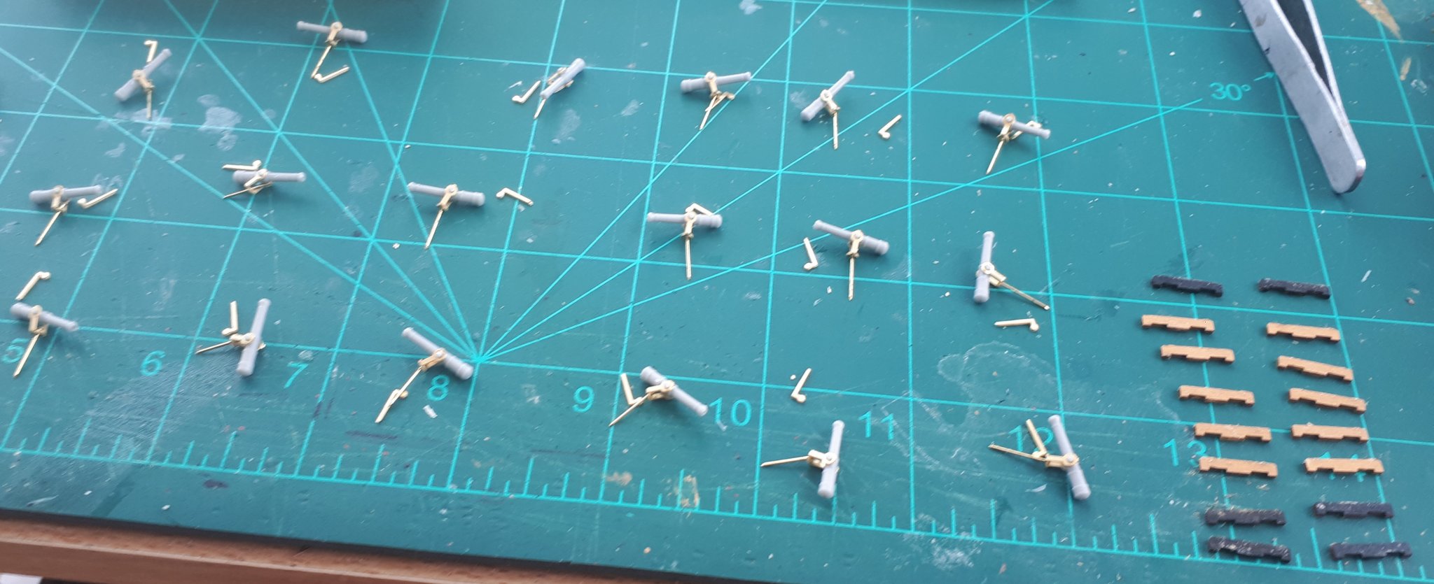
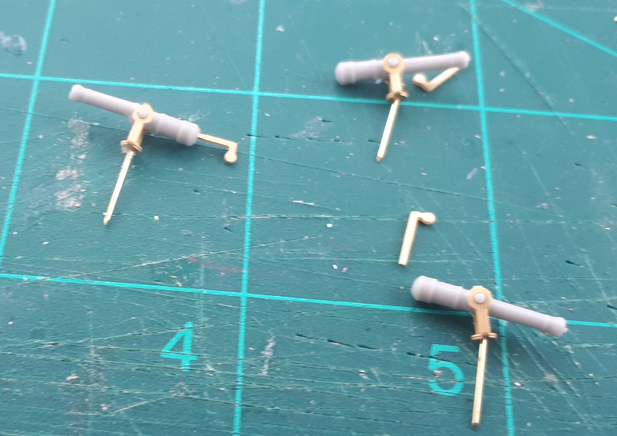
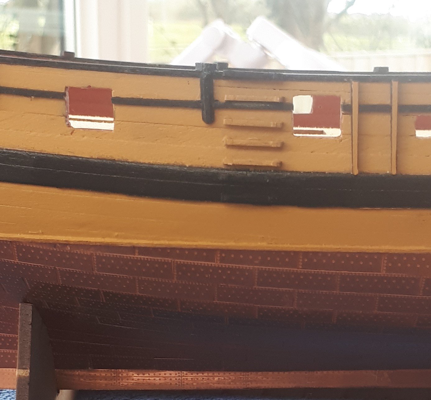
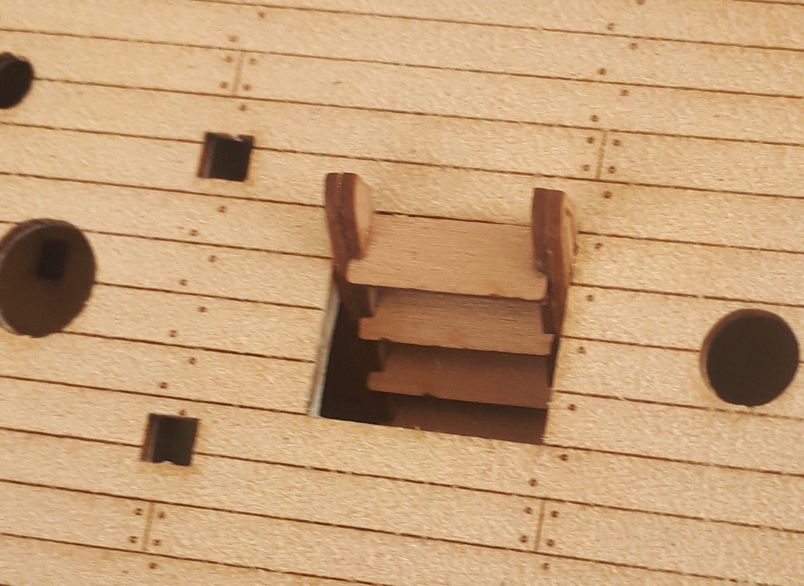
I have started the assembly of the 20 off swivel guns. I am just waiting for a delivery of a new set of micro drills (due later today) as I have snapped all my 0.8mm and 0.6mm drill bits before I can complete this task. In the first picture you can also see the steps painted side steps, in readiness for installation. In the second picture you see one completed swivel gun assembly, prior to snapping my final 0.8mm drill bit.
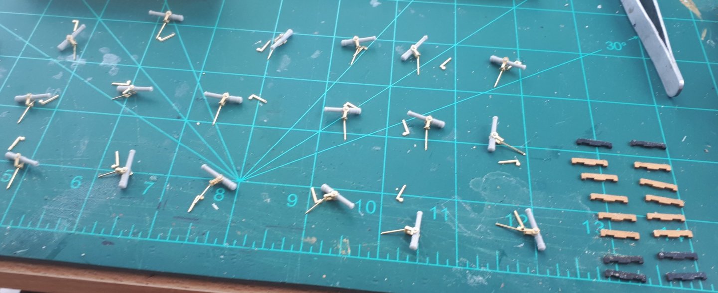
I used some 2mm tape, marked with the position of the steps to help position the side steps.
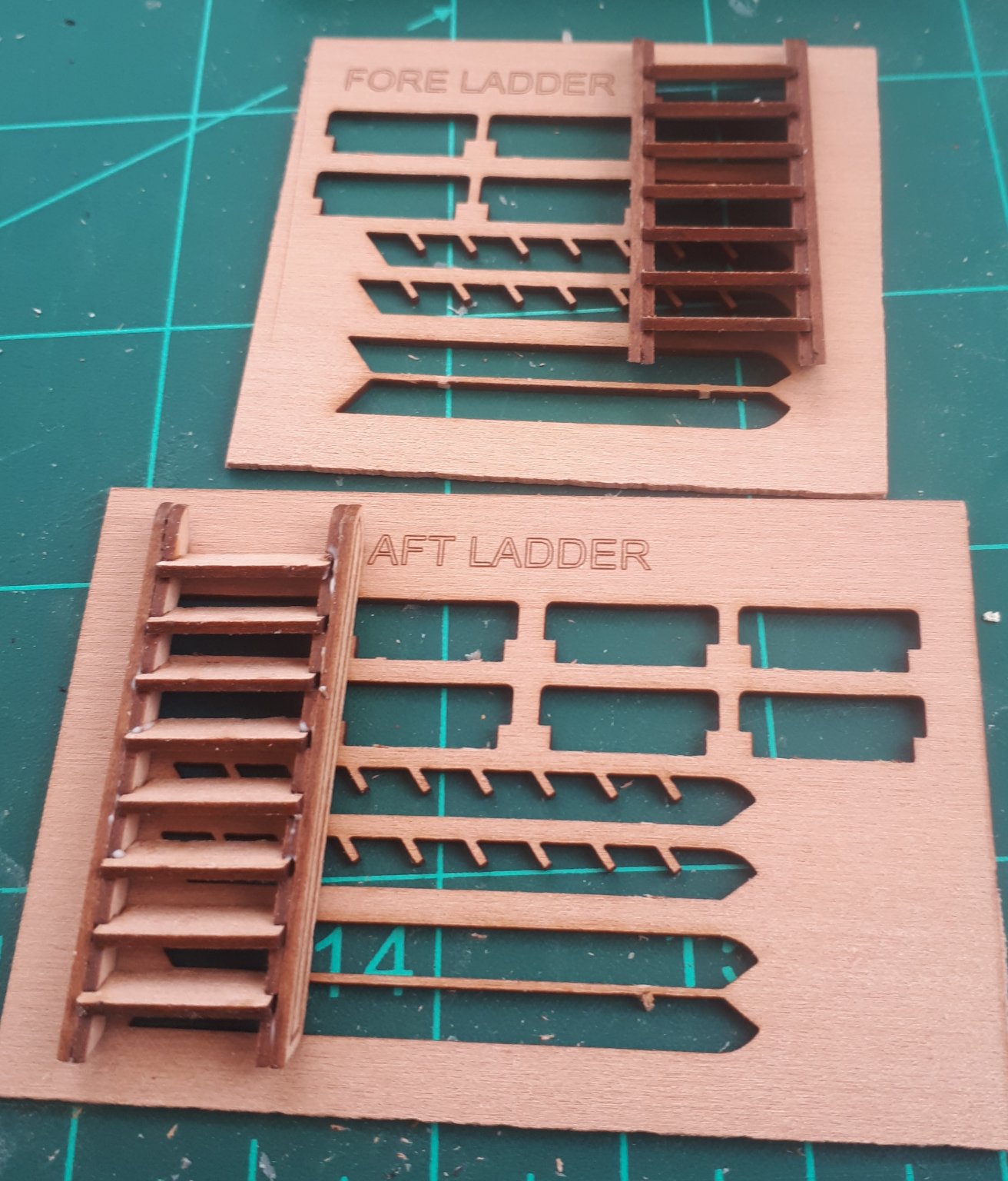
Finally I have also assembled the two ladders and test fitted them.


- GrandpaPhil, Edwardkenway, egkb and 4 others
-
7
-
13 minutes ago, captain_hook said:
Looking good so far. Are stem and stern pieces supposed to be painted black above the coppering?
Yes, I did that before I started the copper plating on my build.
-
3 minutes ago, DelF said:
Believe it or not I'm quite enjoying the coppering, despite the CA fumes. It's a new challenge, and for me that's half the pleasure of modelling.
Having said that, I suspect I may not want to do it again once I've finished Speedy!
Derek
I found Speedy copper plating quite relaxing. My HMS Victory build had approx 3000 copper plates to fit and that did become a tad tedious at times but the end result was worth it on both builds.
-
Catheads and timber heads have now been fitted. I did pin the timber head (part 122) to provide additional support. I also used a 6mm dowel to ensure the is room for the bowsprit to be fitted between the timber heads.


HM Brig-Sloop Speedy by glennard2523 - Vanguard Models - 1/64
in - Kit build logs for subjects built from 1751 - 1800
Posted
A bit more progress today with the Fore Topmast and the Fore Topgallant masts.