


Glenn-UK
-
Posts
3,004 -
Joined
-
Last visited
Content Type
Profiles
Forums
Gallery
Events
Posts posted by Glenn-UK
-
-
-
I have ordered a Proxxon KS230 mini bench saw which should arrive later this week. I think this will help me with the production of the masts. I will be able to make a clear angled cut for the two ends of the bowsprit. I also plan use the bench saw with the fore, main and mizzen mast shaping, helping to make a round dowel square for example. I already have a Proxxon DB250 mini lathe which is great for tapering the dowels.
I have started assembling the gunwale and ribs for the Fore, Main and mizzen masts. These parts were removed from the wooded sheets and glued (wood glue) and then clamped together. I did use a couple of pins to ensure the ribs lined up perfectly with the gunwales.
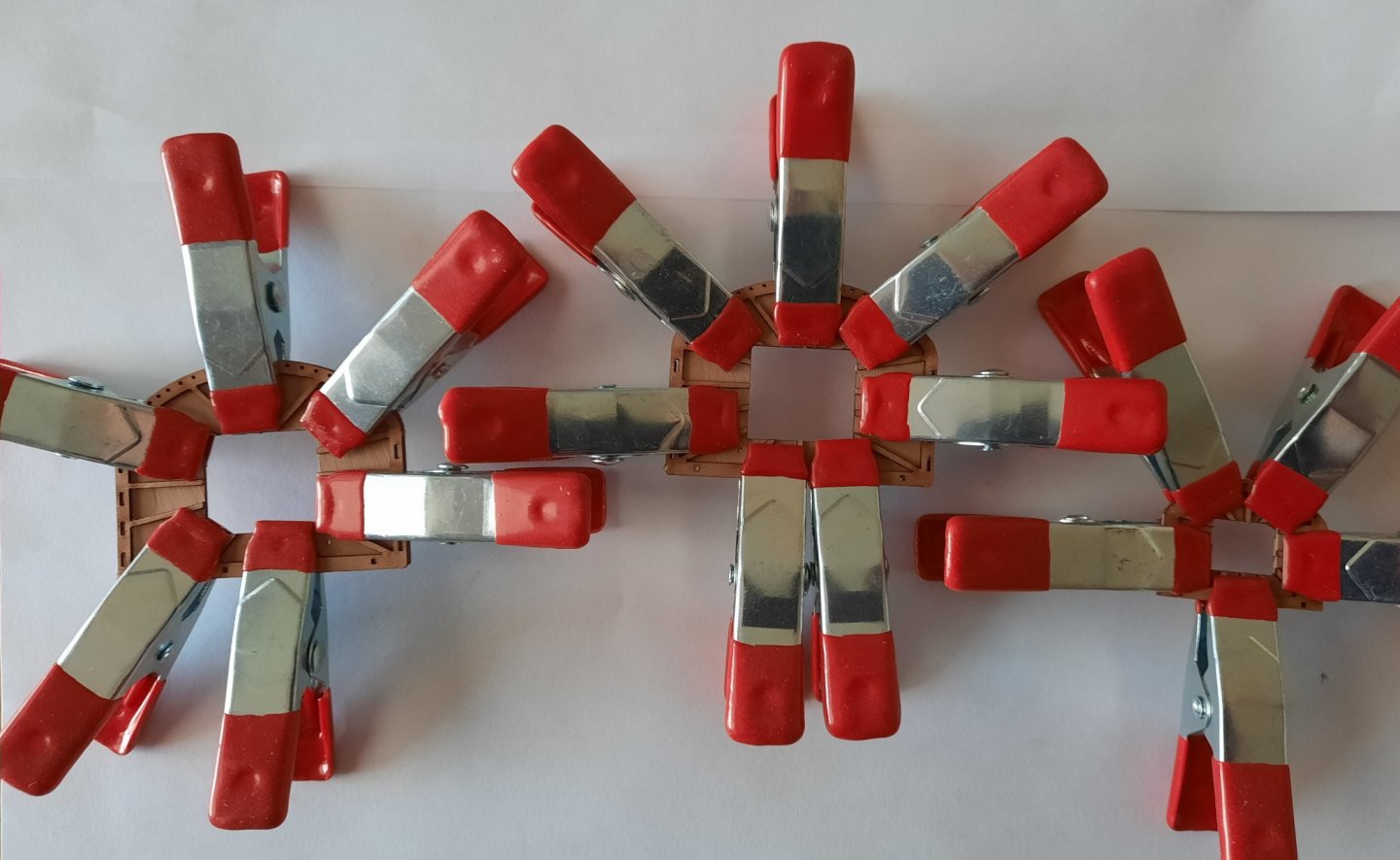
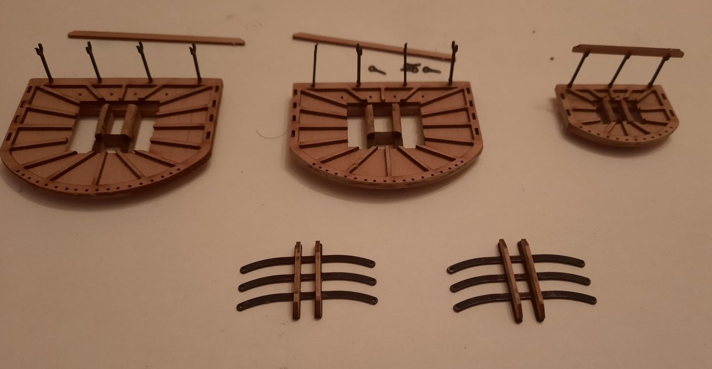
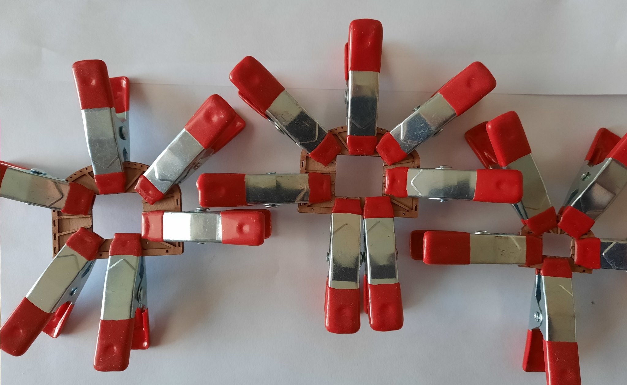
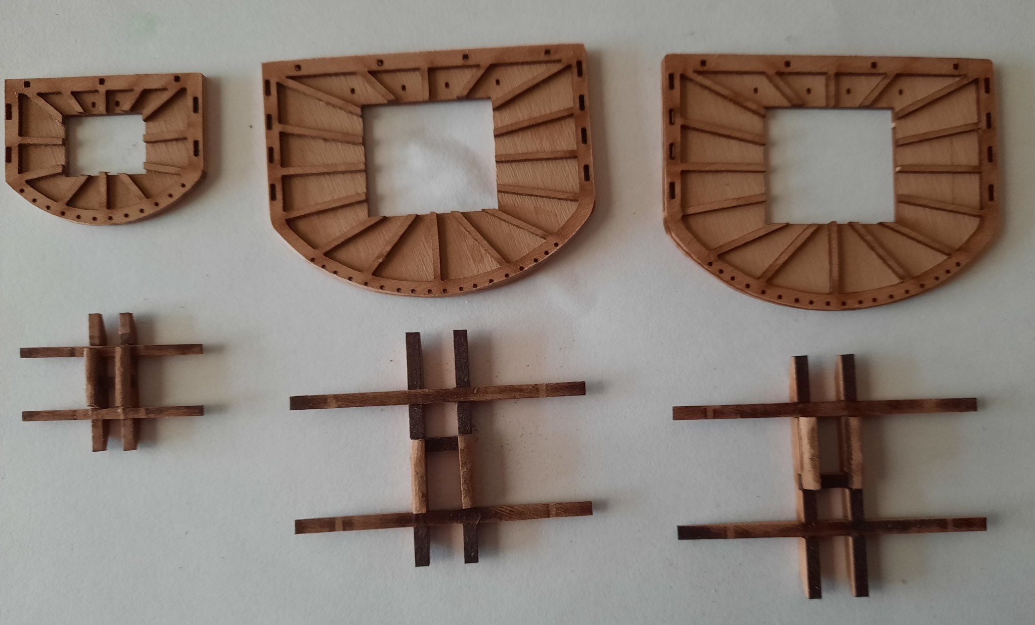
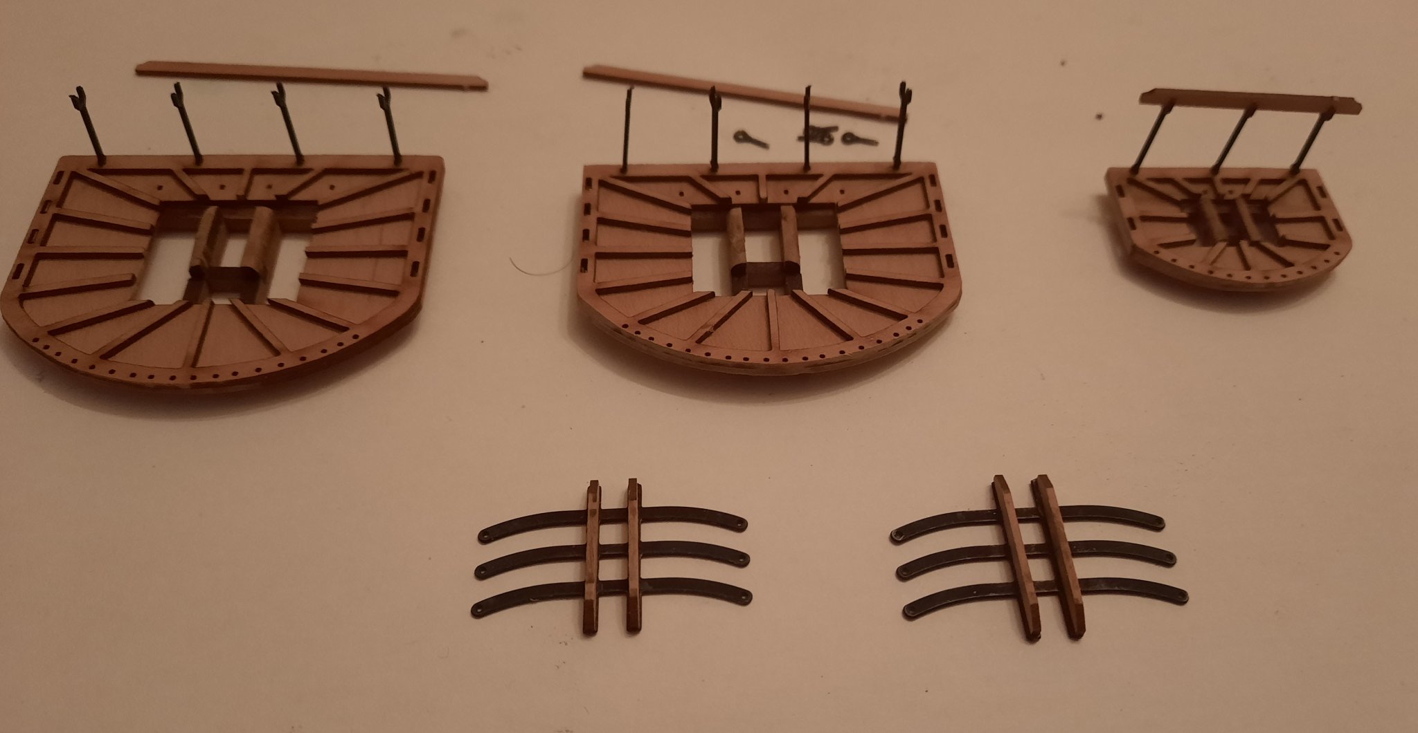
I then moved on to the assembly of the crosstrees and tressletrees required for the platforms. As always, I made sure I had all the parts.
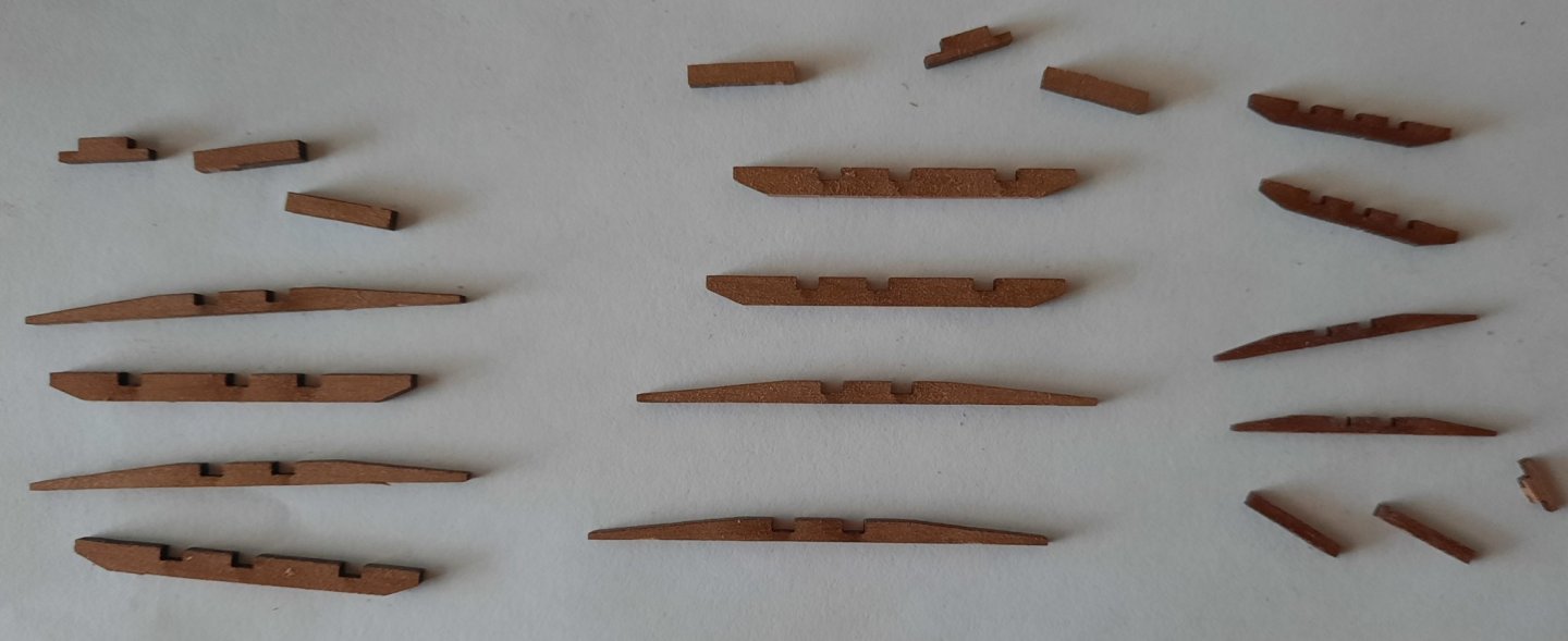
I applied wood glue to the locating slots and assembled. I took great care not to mix up the fore and main mast parts which are very similar. As the glue was cured I rounded the bolsters and then fixed them in place.
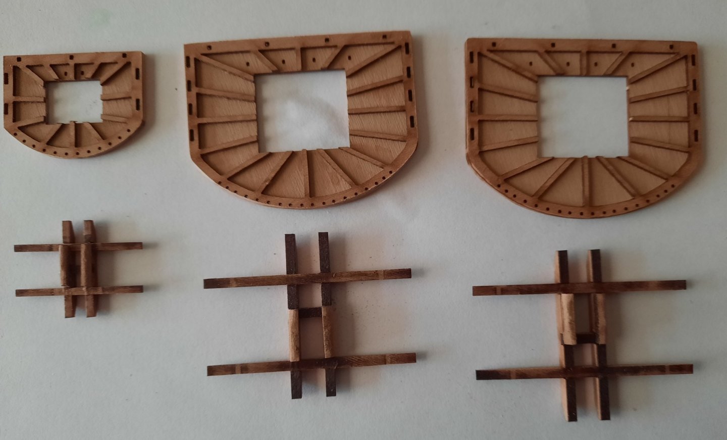
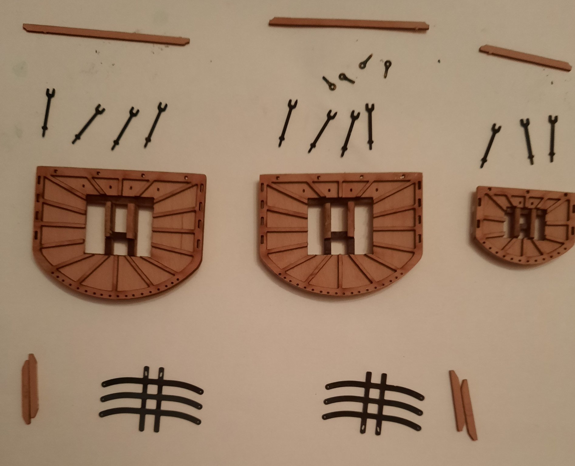
The crosstrees and tressletrees were then glued and clamped to the platforms. Next I started work on the fore and main top mast tressletree and crosstrees. The crosstrees for each tressletree is slightly different so I marked the parts before they removed from the wooden sheet. The two tressletrees were soaked in acetone and then blackened.
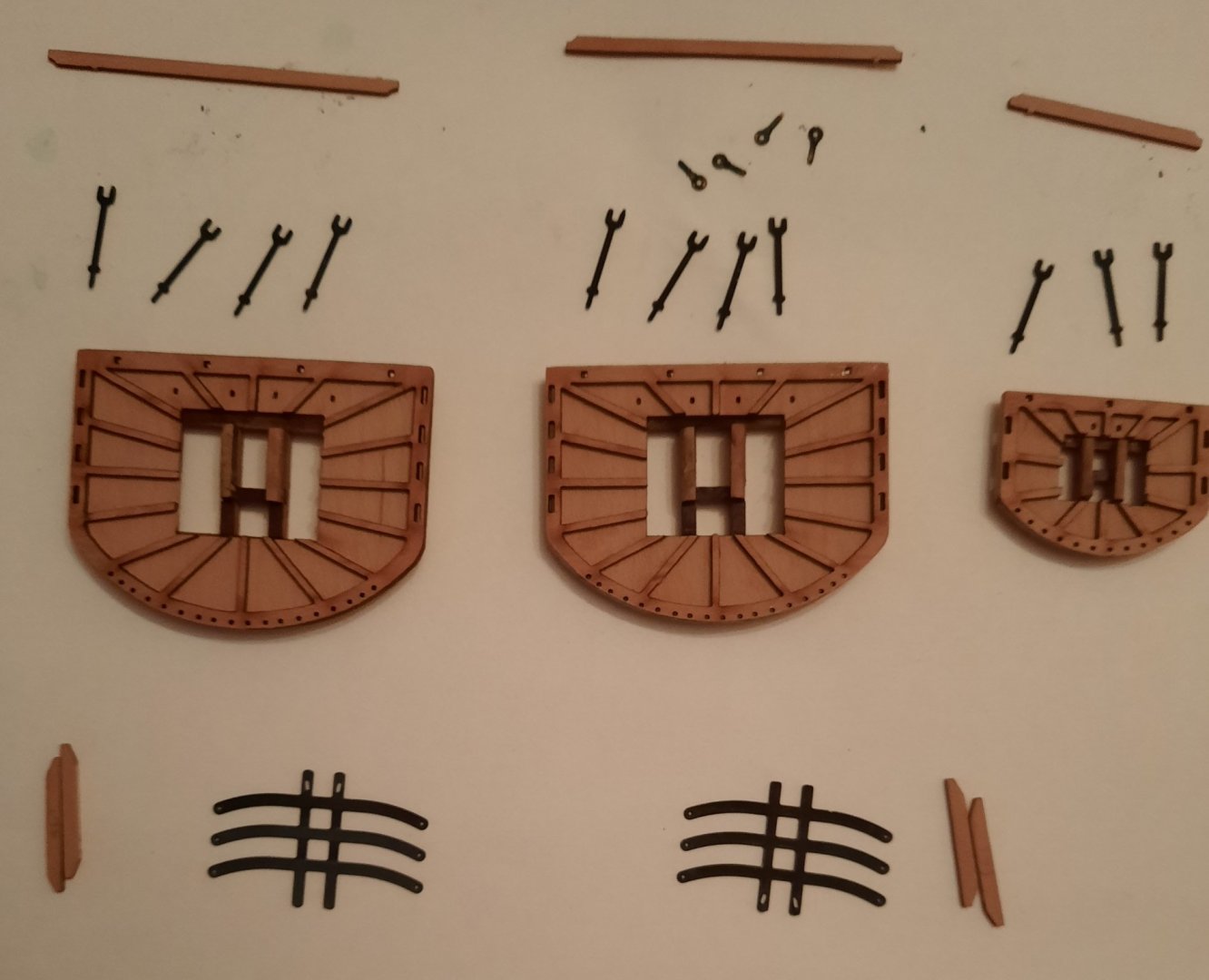
I applied wood glue to the each crosstree and clamped them to their respective tressletree. I also blackened the 11 off lower rail stanchion and test fitted them to the platforms with their associated top rail. I will glue these parts when I am ready to fit these parts to their respective masts.
-
Thats what I did also. I really enjoyed making all the inboard deck items. The grating for the middle hatch needs to be fitted later so the anchor ropes can be added. The other option, if the grating is already glued, is to fit the rope to the middle hatch assembly before it is glued to the deck.
- FrankWouts and Rustyj
-
 2
2
-
2 hours ago, rafine said:
She's looking great Glenn.
Bob
Thanks Bob
-
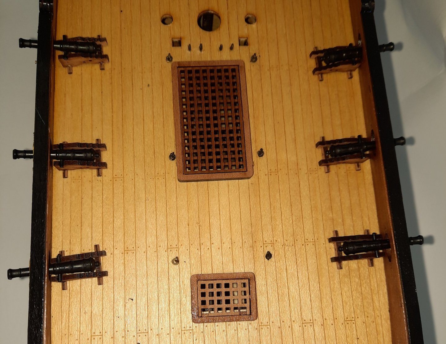
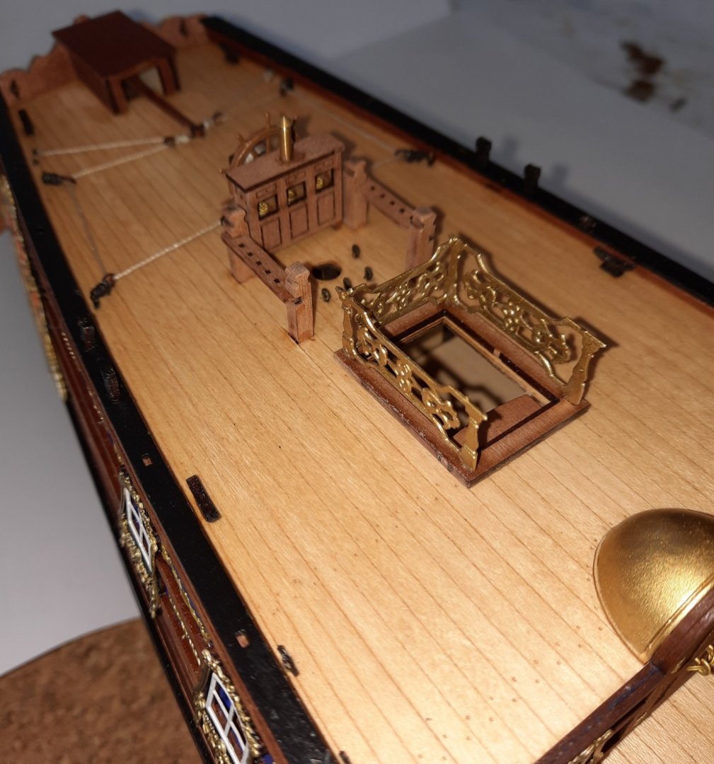
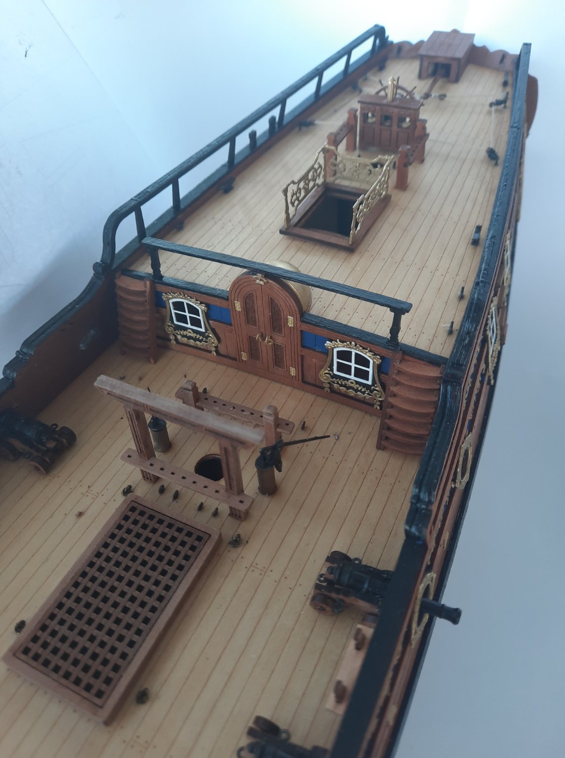
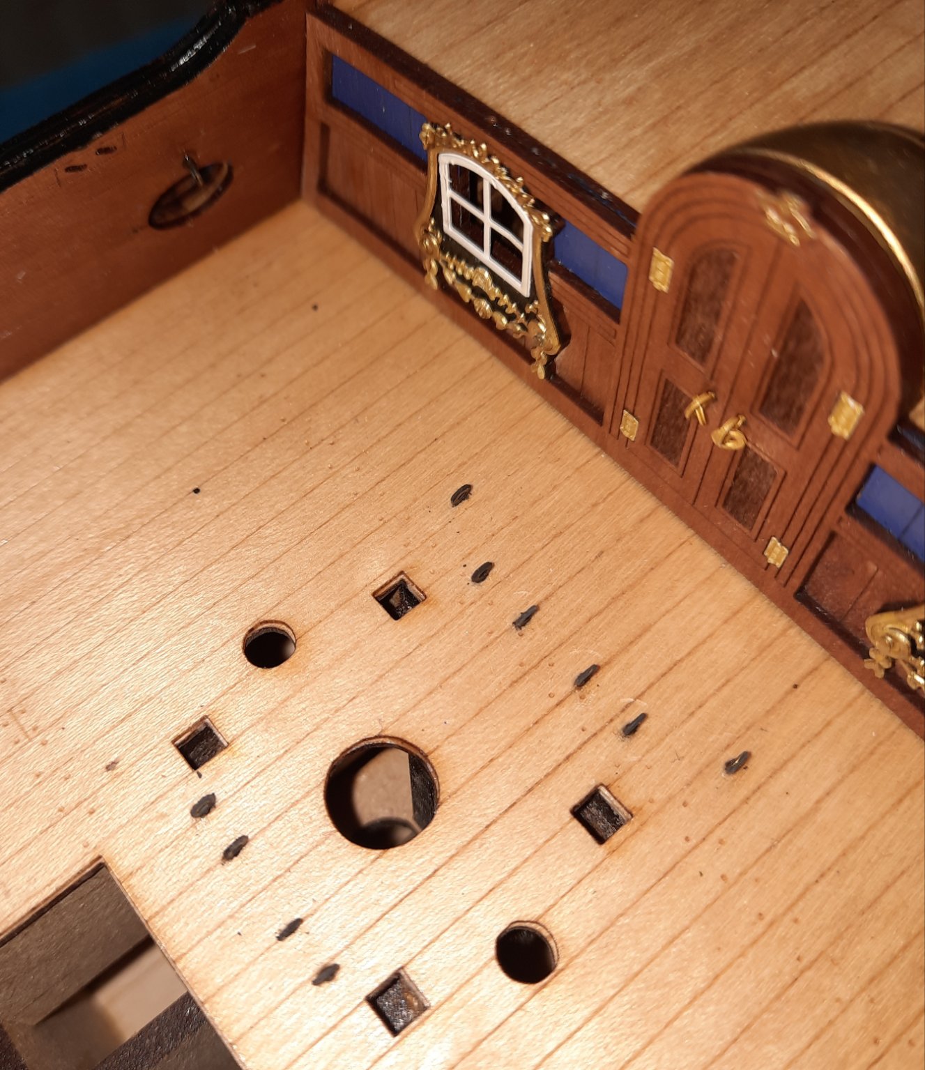
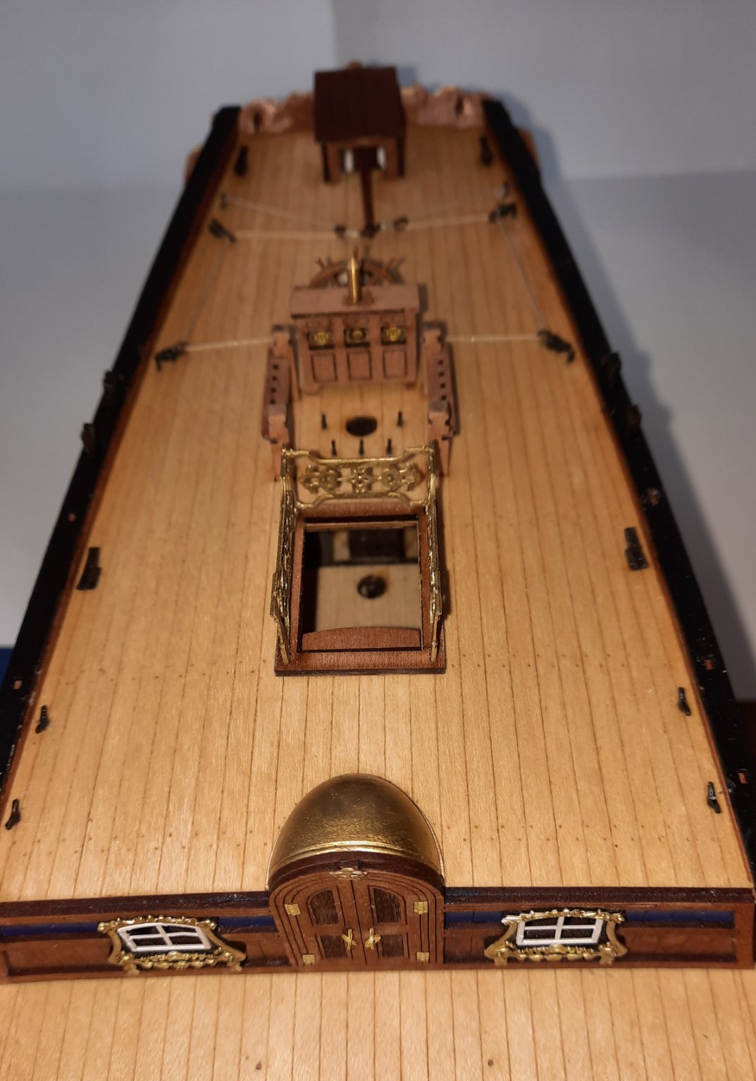
After completing the cannon assembly yesterday I have now fixed the main deck items in place.
Photo of the timberheads
I have test fitted the 6mm dowel which will be used for the bowsprit and there were no problems.
Photos of the deck items.

I made sure the staghorn cleats were installed the right way up, shot garlands are only dry fitted as I need to add the cannon balls.

I like the look of the DOK deck in this photo. The side steps have been fitted. I plan to fit the channels after I have completed the mast and yard manufacture phase.

I will now commence work on the bowsprit. I have made a photo copy of the plan drawings and marked up the key dimensions for the items,

- Edwardkenway, James H, marktiedens and 9 others
-
12
-
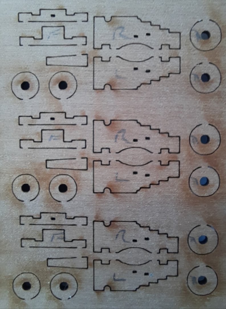
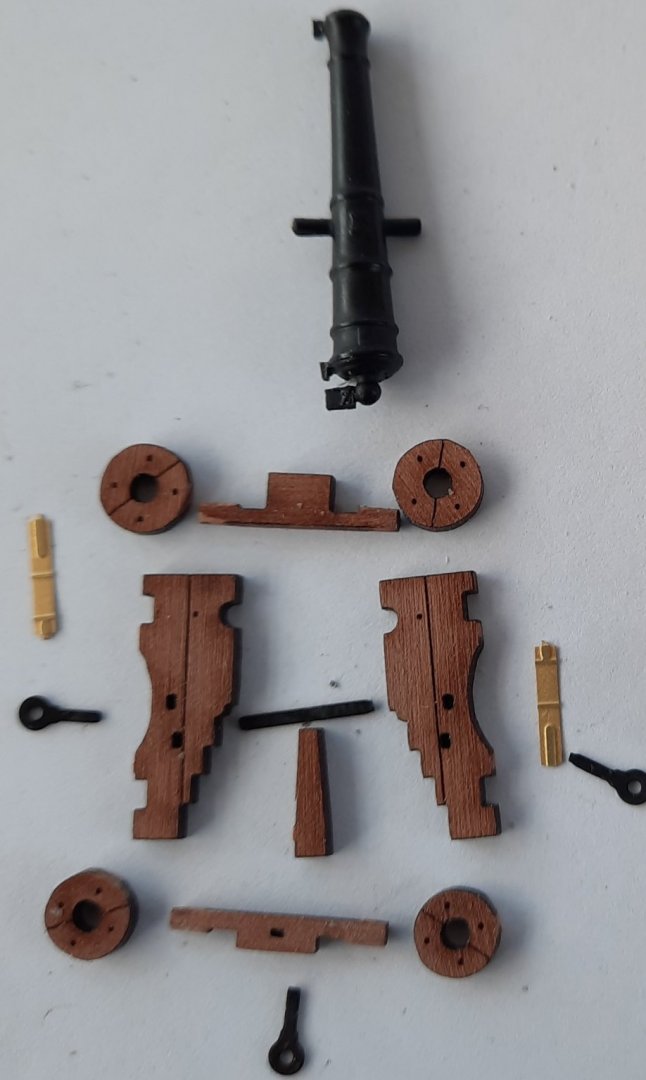
This post details the method I used to assembly the 6 off 4-pounder cannon assemblies. The rigging of the cannons will be covered in a later post. I thought about painting the carriages, red for the sides and black for the wheels and carriage bed but I have opted to leave them unpainted.
Cannon Assembly Stage 1 - Part Identification
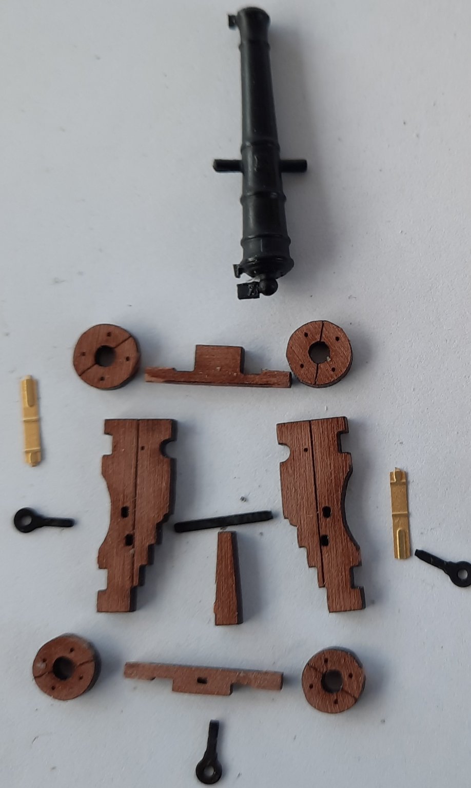
Each cannon comprises several components, which are:
2 x Carriage Sides, 1 x left sided and 1 x right sided
2 x Front Wheels and 2 x Rear Wheels
1 x Front Axle and 1 x Rear Axle
1 x Carriage Bed
3 x Eyebolts
1 x Cross Bolt
1 x 4-Pounder Cannon Barrel
2 x Cannon Barrel Trunnions
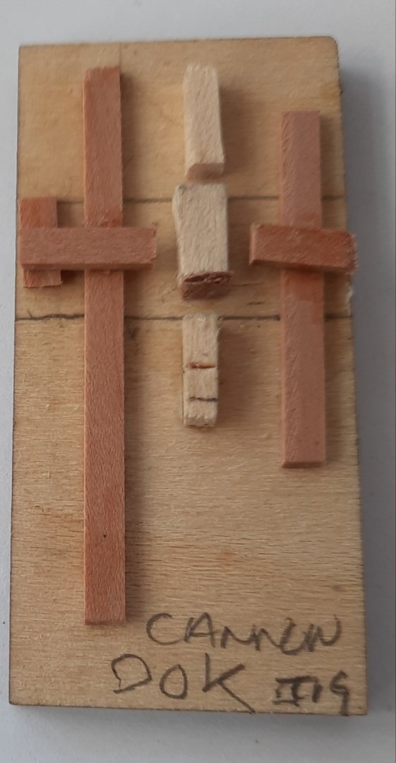
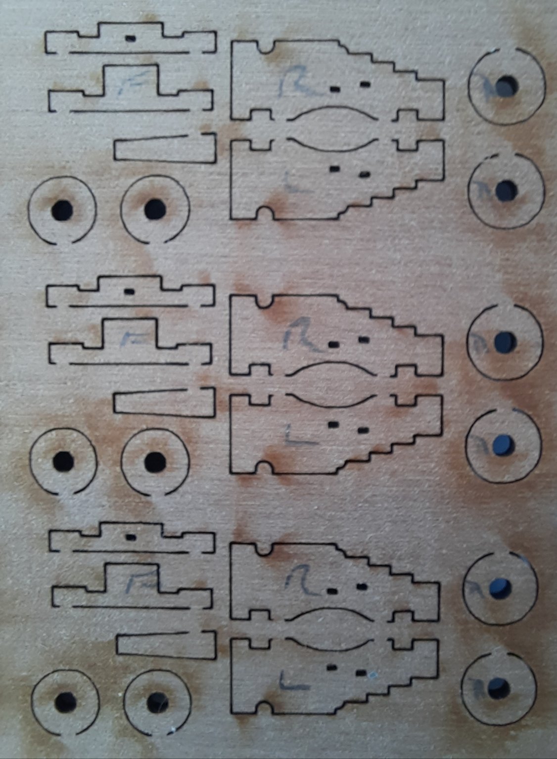
To aid identification, during the assembly phase, I marked up some parts before they were removed from the wooden sheets, as shown in the photo below. This proved to be unnecessary because I ended up removing 1 set of carriage sides and 1 set of axles at time as I assembled the cannons. I also removed one set of wheels which I used to test fit over all the axles once they had been rounded off.
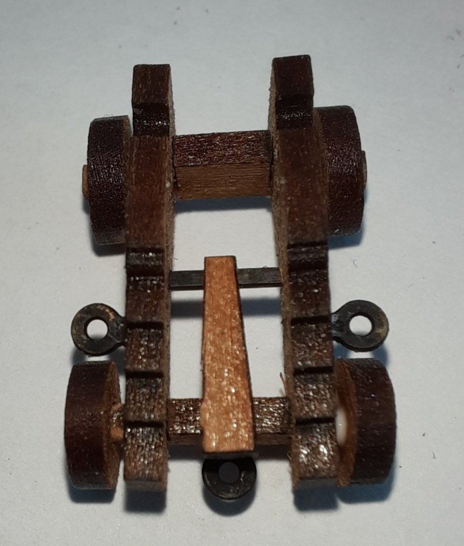
Cannon Assembly Stage 2 - Carriage Frame Assembly
Knowing assembly of the cannon can be fiddley I decided to make an assembly jig to aid the build process. It is not an elegant looking jig, as can be seen on the attached photo, but it was fit for purpose and worked very well.
The first task, using sandpaper (320-grit), was to slightly round the axles. I did a couple of test fits of the wheels during the rounding process.
The two axles were placed in the jig. I then applied a touch of wood glue in the axles locating slots for the two carriage sides and the carriage sides were then positioned in the jig. The cannon was left in the jig for a few mins to give time for the wood glue to grip. I used this time to round the axles of the next cannon.
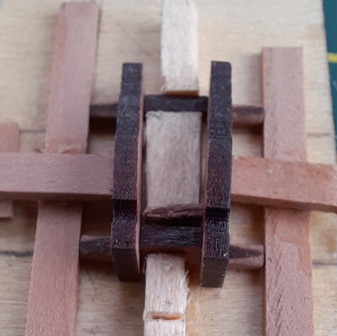
It did not take too long to assembly all 6 cannons carriages, as can be seen in the photo below.
Cannon Assembly Stage 3 - Completing Carriage Assembly
The cross bolt and 3 eyebolts were test fitted and then removed so the excess material could be trimmed, using a sharp craft knife blade. The cross bolt was then reinserted without any need for glue (in my opinion). I applied a small amount of ca gel to the three eyebolts stems and they were then correctly aligned and inserted. Next the 4 wheels were added to the carriage assembly. A touch of wood glue was placed on each wheel axle and the wheels were then pushed on. I did my best to ensure the wheels looked level with the sides of the carriages.
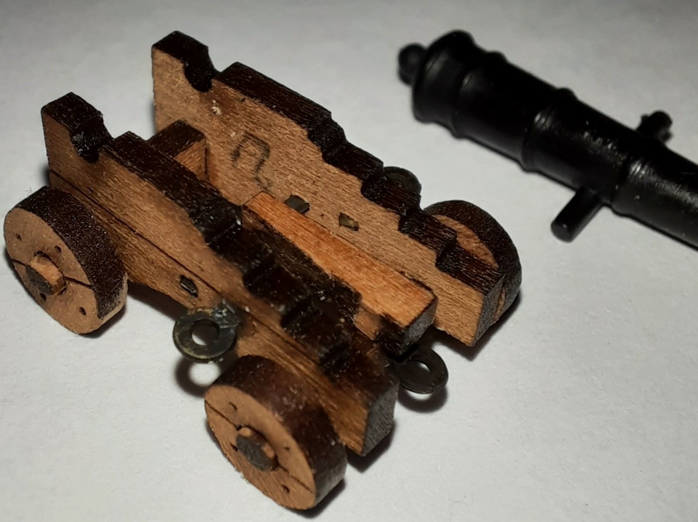
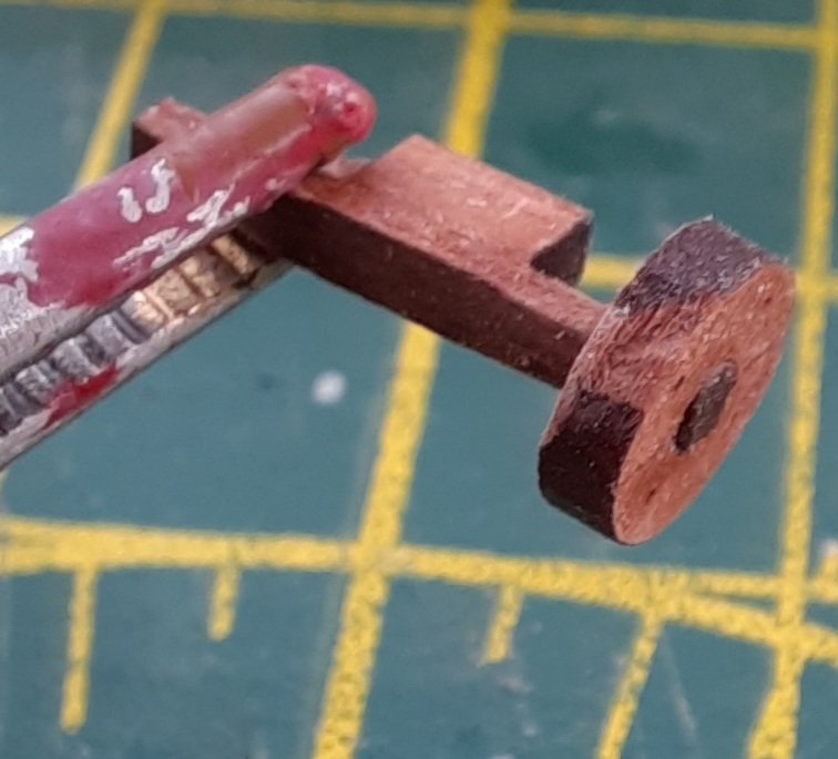
Cannon Assembly Stage 4 – Adding the 4-pounder cannon barrel and 2 off trunnions
On inspection of the 6 off 4-Pounder cannon barrels I noticed some excess casting resin which needed to be removed. This was done, very carefully, using a sharp craft knife. The 4-Pounder cannon barrel was placed in the carriage assembly using a touch of ca gel. There is an emblem on each cannon, so it is important to make sure this is face up.
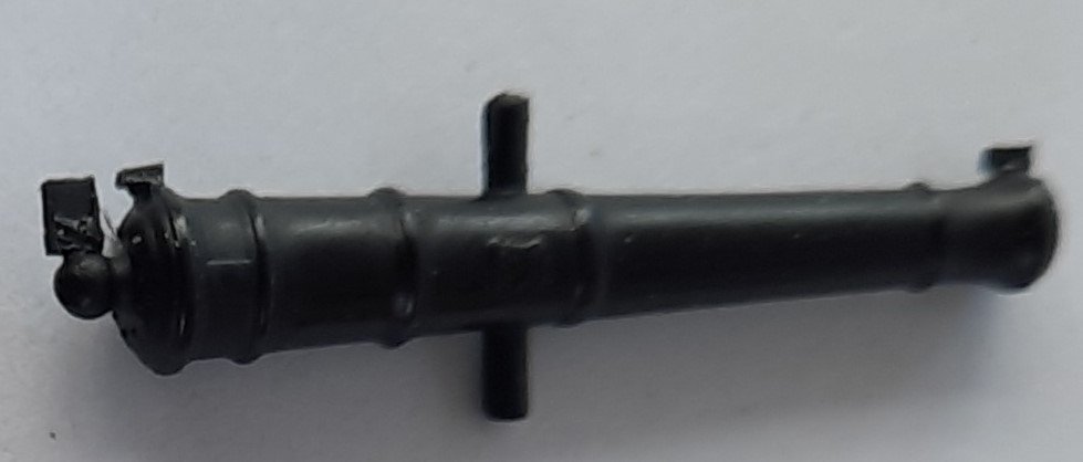
I found the shaping of the trunnions over the cannons pivot arm to be the most time consuming and fiddley part of the cannon assembly process. Initially I used my small round nose pliers but I was not totally happy with how they looked so I decided to make as jig to allow the trunnion to be shaped consistently to fit over the cannon barrel’s pivot arm. I made a small slot and glued a small length of copper wire in the slot. I then added some guides (both sides and at the top) which allowed the trunnion to be correctly positioned over copper wire. I then applied pressure on the both sides of the trunnion to get the required shape. This worked very well and made this task much easier and quicker.
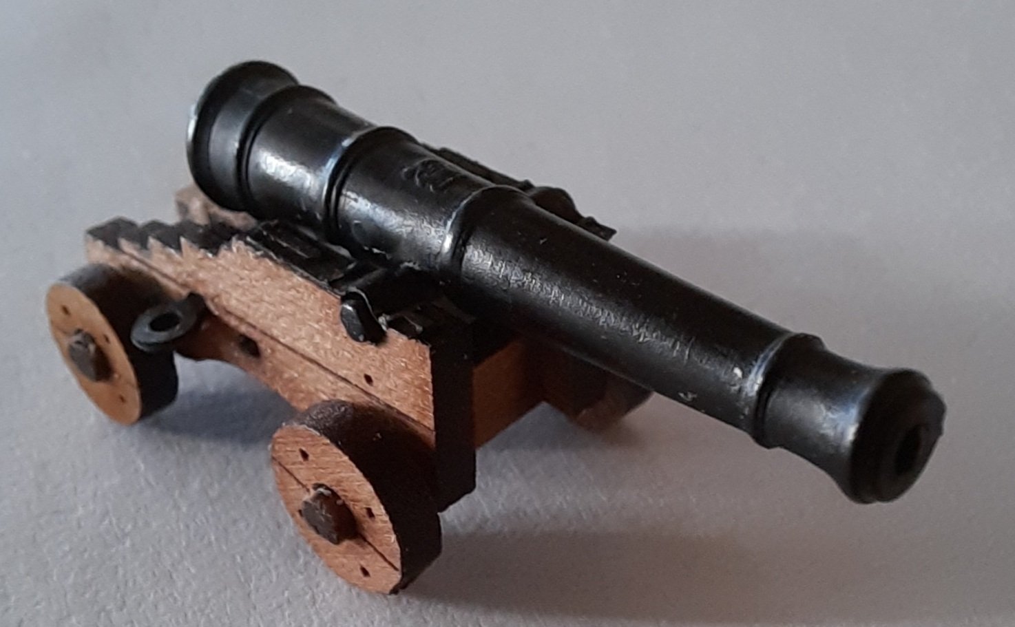
Once the trunnions had been shaped, they were placed on the carriage to check they were sitting flush. I then used ca gel to fix in them place, by applying small drops on the carriage. The ca gel allows a little bit of time to adjust the trunnions in the correct position. The end result is a nice looking 4-pounder cannon assembly.

-
Nice work, she looks amazing
- Rustyj and FrankWouts
-
2
-
Nice work, looks very good. You are making very good progress.
I have just completed the assembly of the 6 off 4-pounder cannons. I should be moving on to yards and masts next week. I'm waiting on a delivery of some thin fly tying thread I've ordered before I can start rigging the cannons.
- Old Collingwood and Rustyj
-
2
-
16 minutes ago, DelF said:
Blimey, I thought Jim was fast!
More great progress Glenn, which I'm following with interest though I'll probably read it all again when I eventually start my Duchess. I was particularly interested in your method for folding the stove - I managed to break mine on Speedy which resulted in much swearing and ca!
Derek
Thanks Derek
Bring retired means I have plenty of free time and as I really enjoy making the small sub assemblies I do tend to spend all day in the shipyard. I have had issues with stove chimney ( and folding other PE parts) on previous projects. I saw a video on YouTube by John Builds Iconic (when I was building Yamato) which used a two steel ruler approach to fold delicate PE parts. I simply added the clamping element for the stove chimney.
-
2 minutes ago, James H said:
She's coming along real quick. Looks like you'll be on the masts before too long.
Thanks Jim
The masts and yards will be next on the agenda once I have built the 6 cannons, which I'm also planning to rig (breach and rear tackle).
- Rustyj and chris watton
-
2
-
This post details the method I used to build and install the two step assemblies, including the left & right aft deck rails, the two quarterdeck gunwales and the quarterdeck rail.
Ladder Assembly
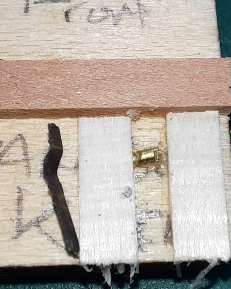
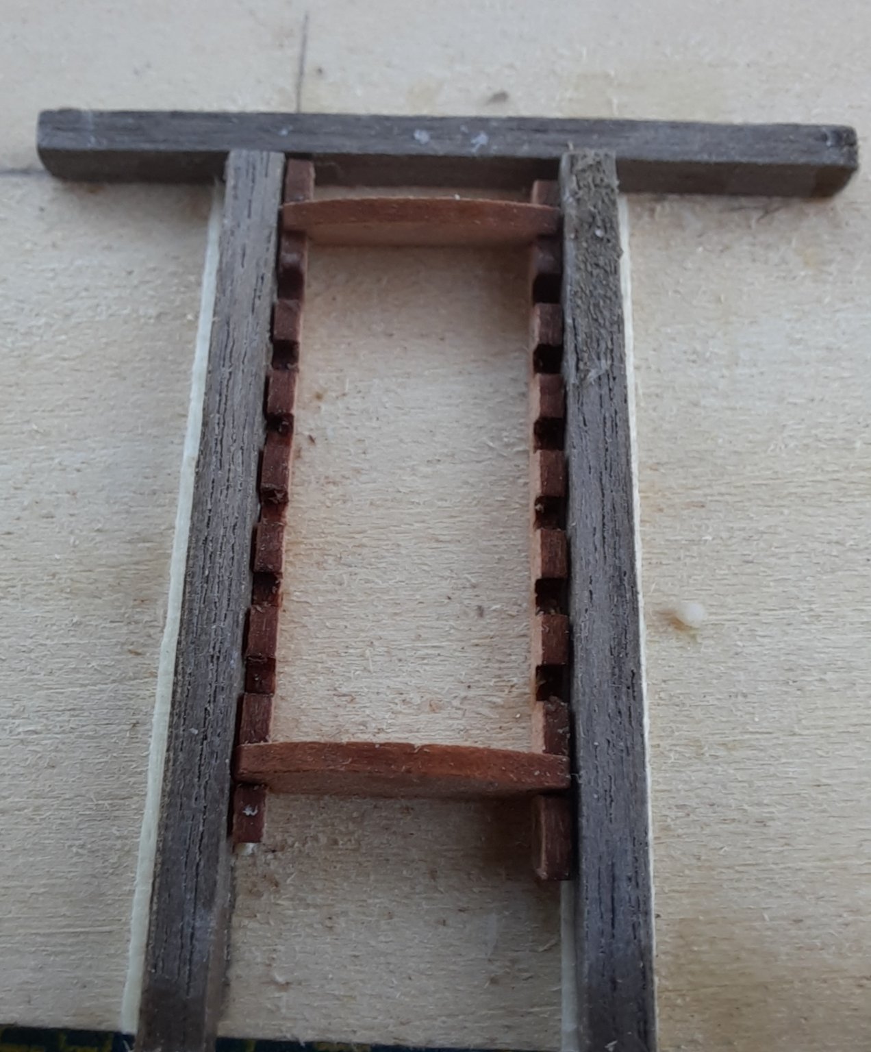
The steps comprise an inner and outer ladder side. These have been designed to account for the curvature of the deck. When I removed the ladder sides from the wooden sheet I added a small pencil mark on the two outer ladder sides for ease of identification during the actual assembly stage. There are 8 steps per ladder and a decorative fascia patterns for the two inner ladder sides as shown in the photo below.

Knowing assembly of the ladders can be fiddley I decided to make a simple jig to aid the assembly process. This was easy to make and the jig I used is shown in the next photo.
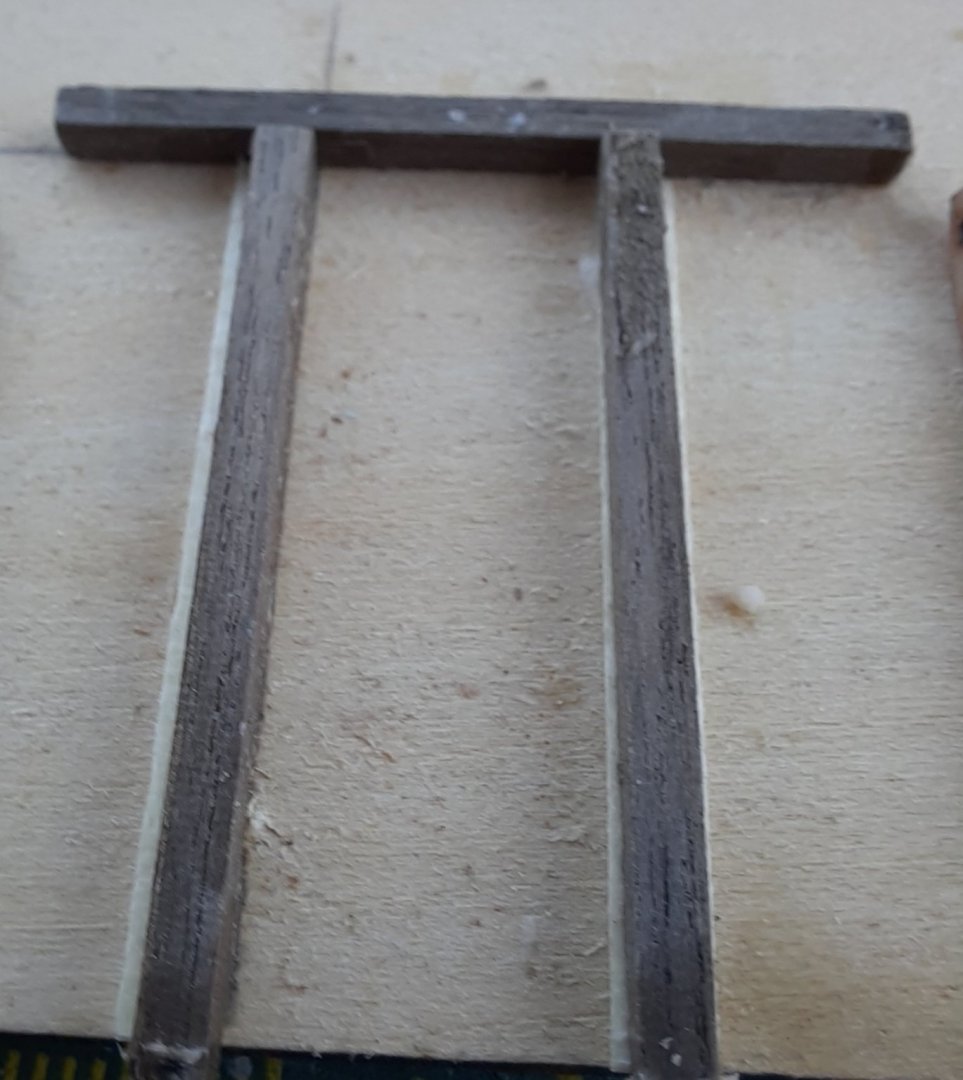
The two ladder sides were then placed in the jig and the top and bottom steps were dry fitted as shown in the next photo.
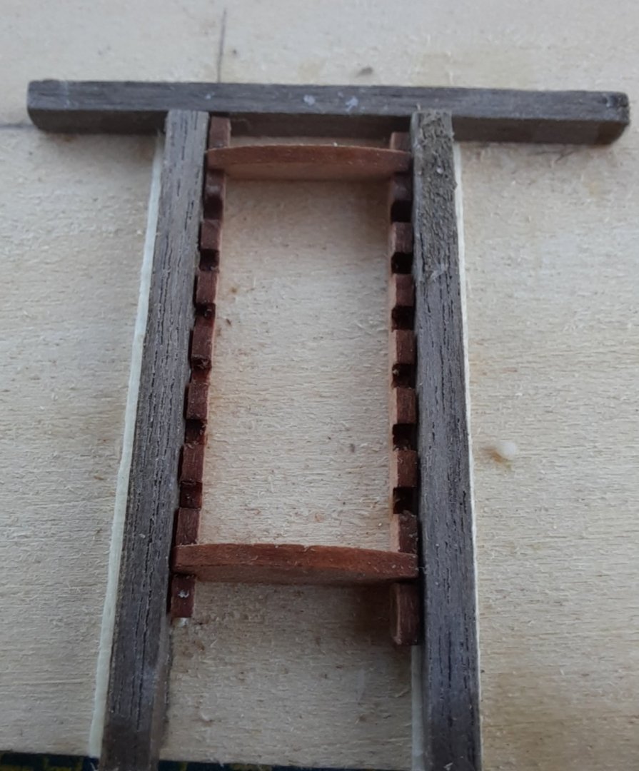
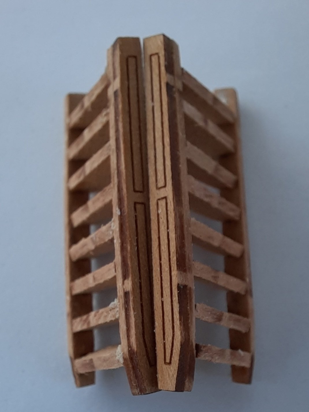
Once I was happy with the alignment of the steps, I proceeded to glue the steps in one by one. With the two dry fitted steps still in place I started with gluing the two central steps. I then removed the top dry fitted step applied some glue and replaced. This was followed by the bottom step. It was then a simple process to add the final four steps.
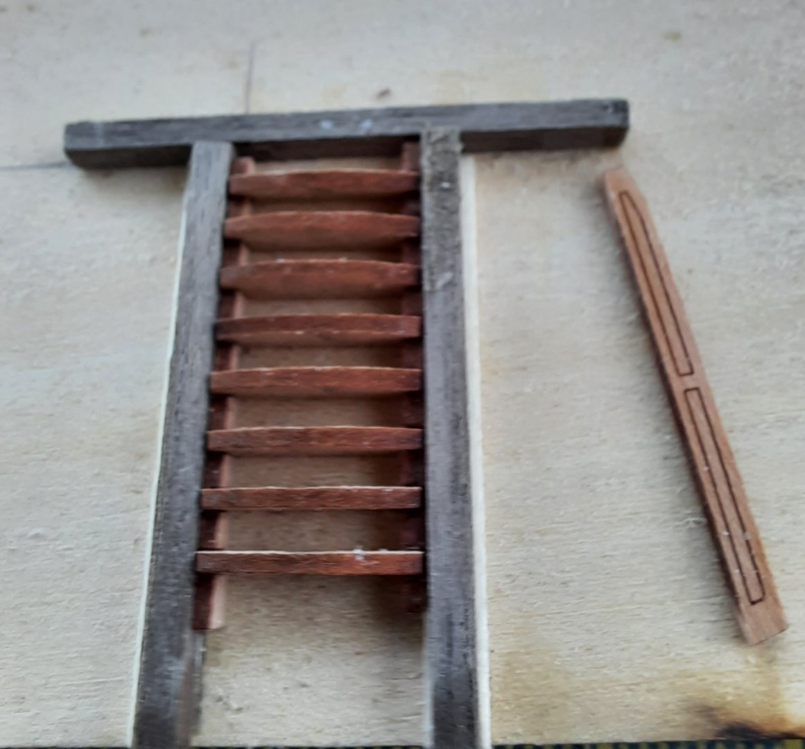
The assembly was removed from the jig and the inner side fascia pattern was then added. The steps are now ready for installation. However before this can be undertaken the left and right aft deck rails, the quarterdeck rail and the two quarterdeck gunwales need to be fitted.

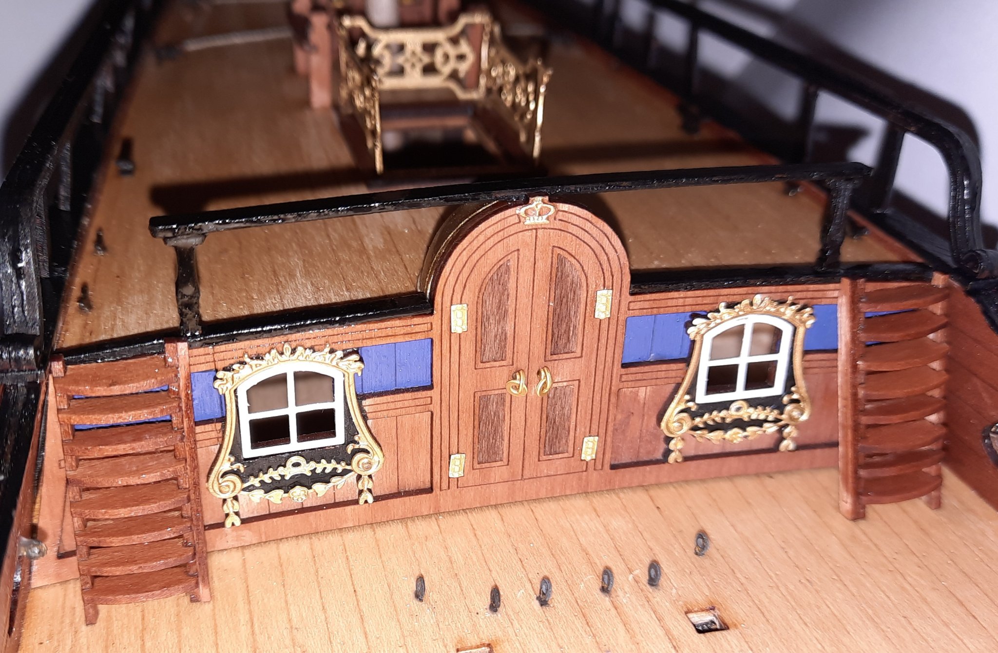
Aft deck rails, Quarterdeck Gunwales and Quarterdeck Rail
The aft deck rails, quarterdeck rail and quarterdeck gunwales were painted black before being removed from their respective wooden sheets. I then used the following assembly method:
a) The left and right aft deck rails were both dry fitted in the locating holes on the two quarterdeck gunwales and the quarterdeck rail. No problems were encountered.
b) The aft deck rails were then glued to the quarterdeck rail.
c) The two quarterdeck gunwales were installed on the quarterdeck with ca gel, noting the outboard edges required a slight bevel to match the line of the bulwarks.
d) The quarterdeck rail, complete with aft deck rails, were then glued in place. I found there was enough flex in the quarterdeck rail to create the required bend over the canopy. I used ca gel to secure this part.
Final Installation
The two assembled step assemblies were glued in place, using wood glue and then I applied a thin coat of polyurethane varnish to the completed assembly. The final photo shows the completed installation noting the varnish is still wet. Next on the build list is the assembly of the 6 cannons.

- ObviousNewbie, marktiedens, DelF and 10 others
-
13
-
1 minute ago, chris watton said:
Great work Glenn!
Just do not forget to turn those cleats over before gluing them.
Great spot Chris. They will be the right way up when glued in place. I was more interested in how they fitted in the locating hole at this stage. Many thanks for your positive comments also.
-
Today’s tutorial is about the method I used to assembly the Stove Chimney. I thought this might be of some interest because I have trouble getting good clean bends on previous models. The method outlined below has solved the problem for me.
I have also added a small section on the 4 off staghorn cleat beams in this post.
Stove Chimney Assembly
The first task, as always, is to ensure I have all the bits available before making a start. I painted the wooden base black before removing it from the sheet. The stove chimney (photo etched part) was cleaned in an acetone solution to remove the contamination and to ensure the surface is ready to take the primer coat.

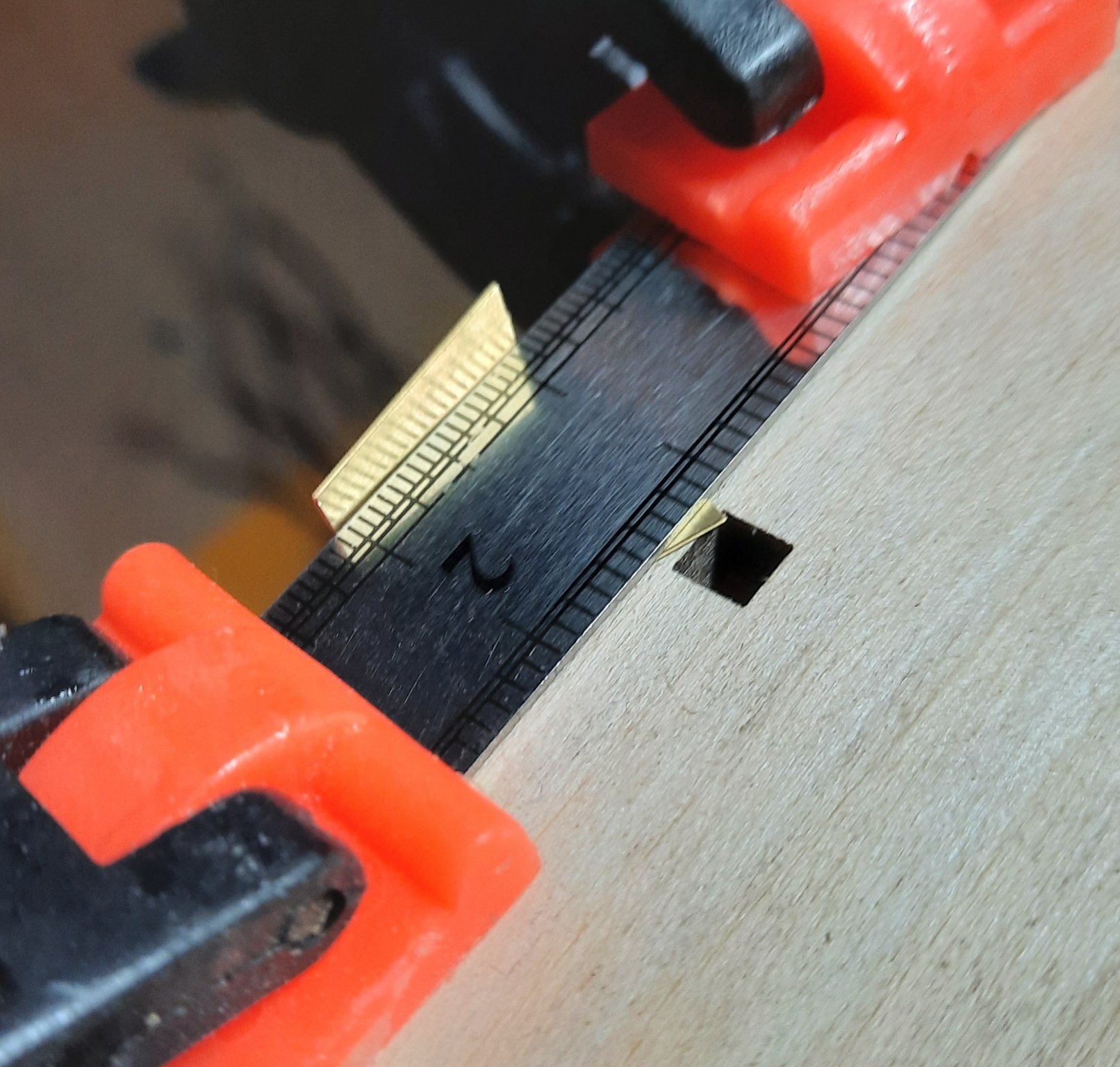
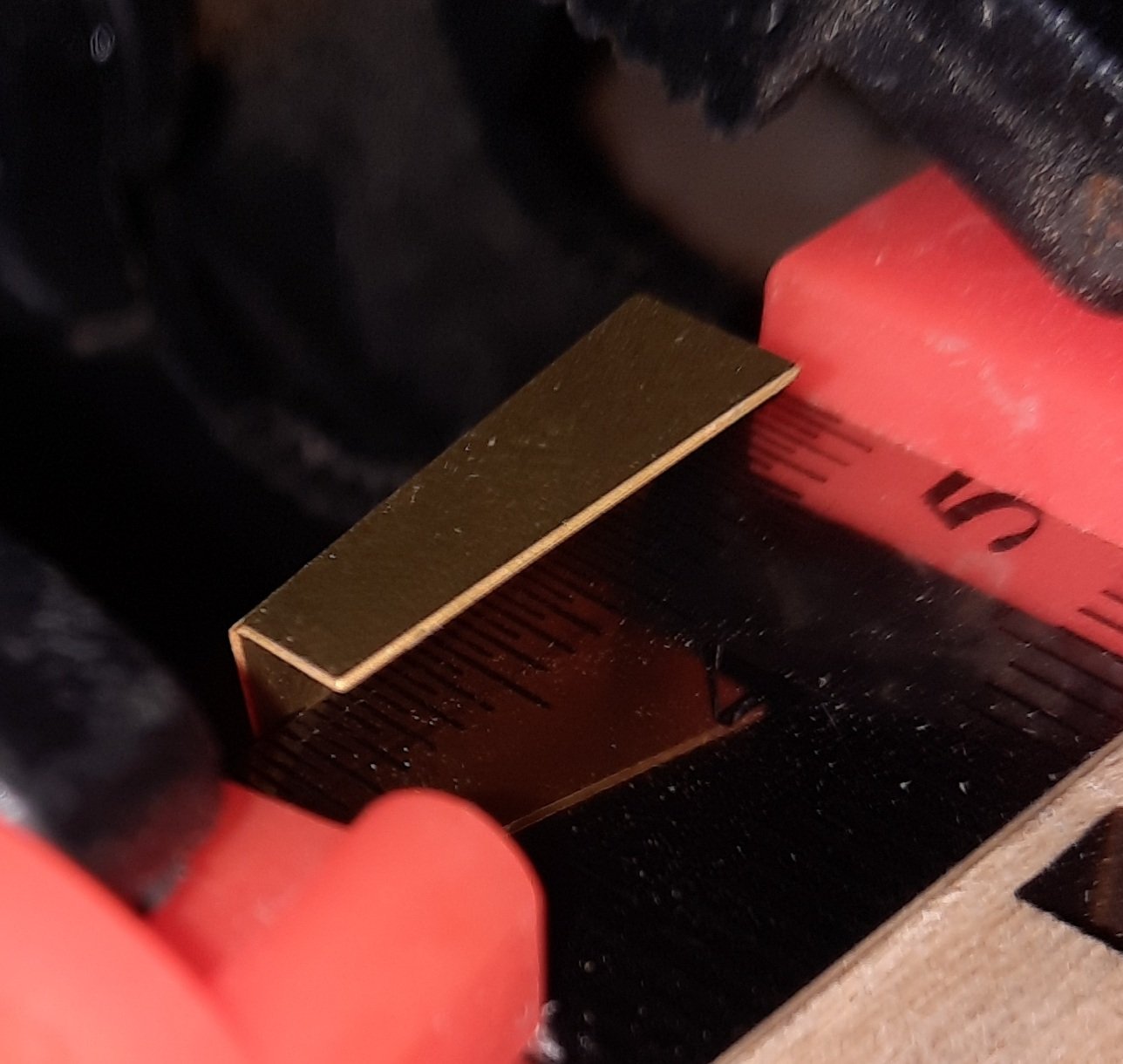
The next task was to fold the PE stove chimney part. To do this I placed the stove chimney (photo etched part) on a wooden base with the fold line along the straight edge. I then clamped a solid straight edge item on top of the stove chimney. I found a steel ruler to be an ideal tool for this. I then applied pressure along the fold line to get a clean 90-degree fold. I used another steel ruler to help with this bending process. I repeated this bending process along the other fold lines until I had completed the folding process.
Stove Chimney has been clamped and is now ready for first fold.
First fold completed.

Second fold completed.

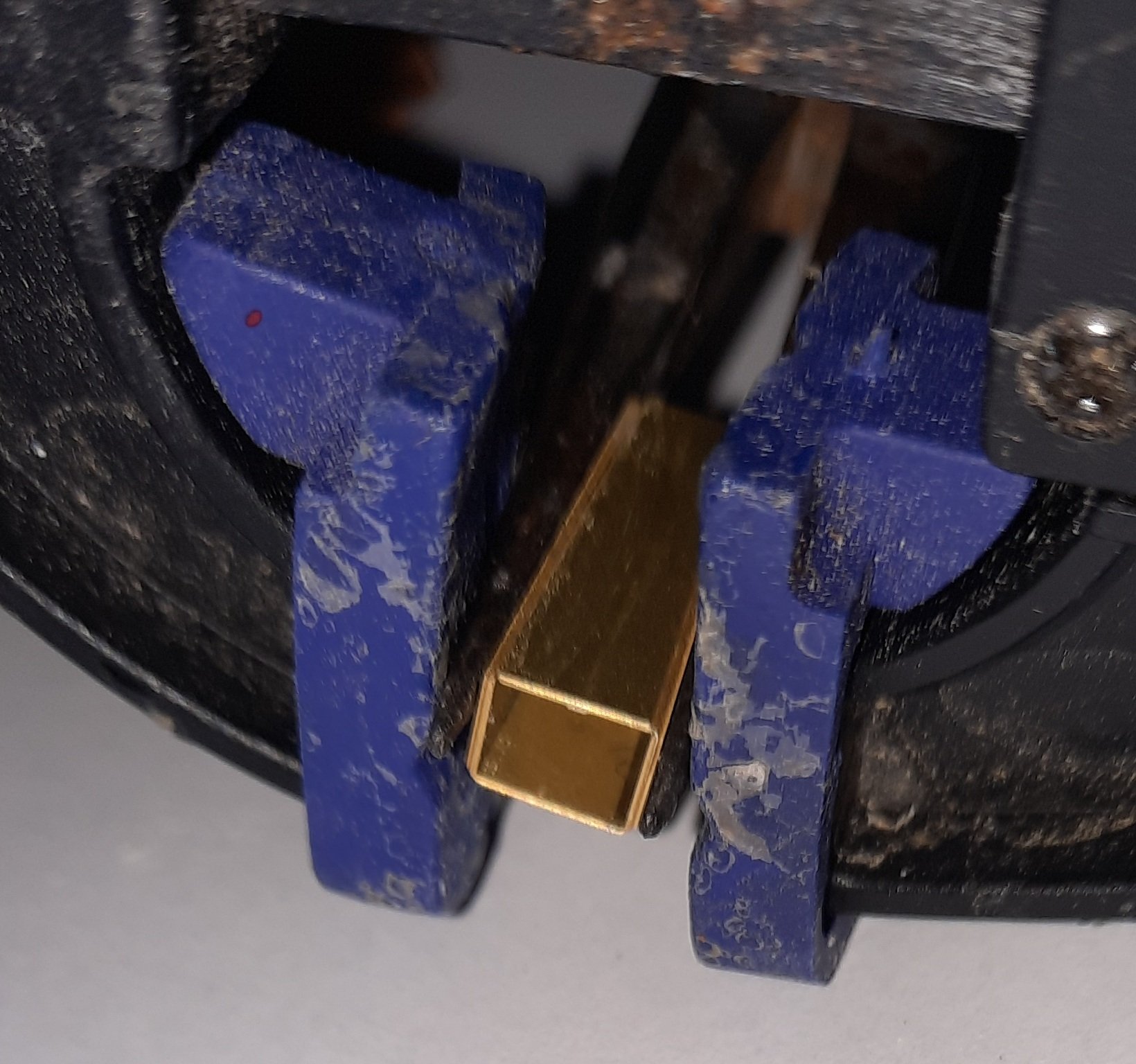
I applied a light touch of ca along the joint line. The stove chimney was then clamped to allow the ca to fully cured.

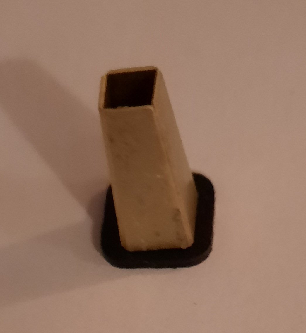
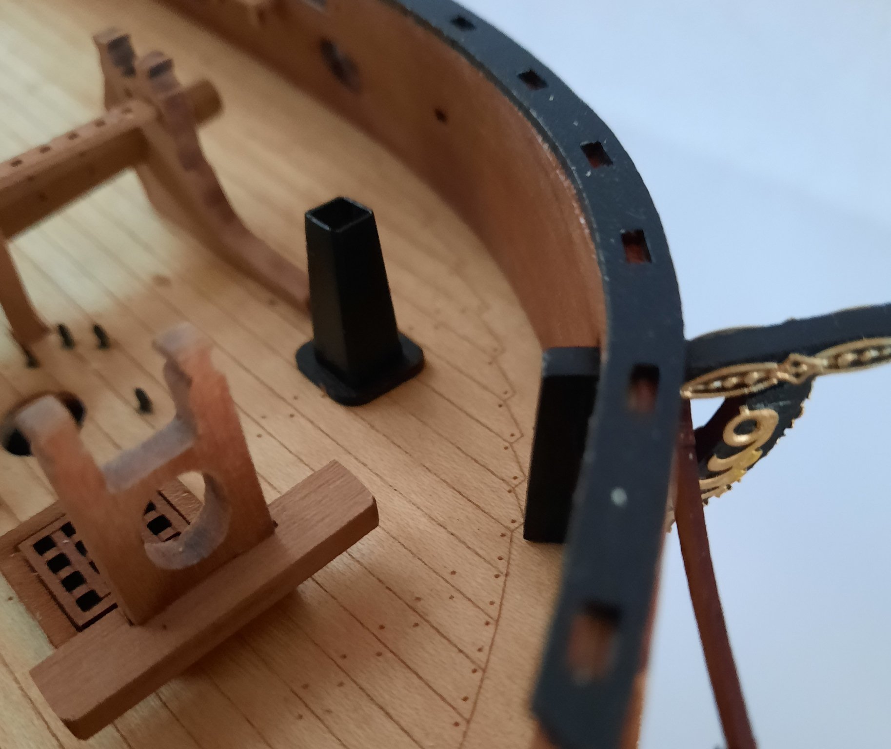
The result is a perfectly bent stove chimney, which is now ready to be primed and painted black.

In the paint shop I sprayed on a coat of white primer. I then gave the stove chimney a light sand with some 800-grit sandpaper before spraying on two coats of black paint. I did give the part a light sand between coats of black paint. The result is a very nice-looking stove chimney, fit for the Duchess.

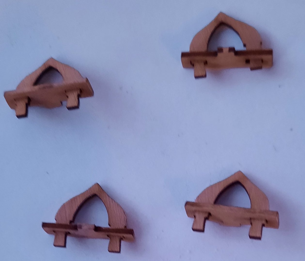
Staghorn Cleat Beams
The staghorn cleat beam assembly was a very easy job and requires very little explanation. I have included a picture of the parts prior to the manufacturing process, noting the 4 off staghorn cleat beams shown are only dry fit assembly to check everything fits.
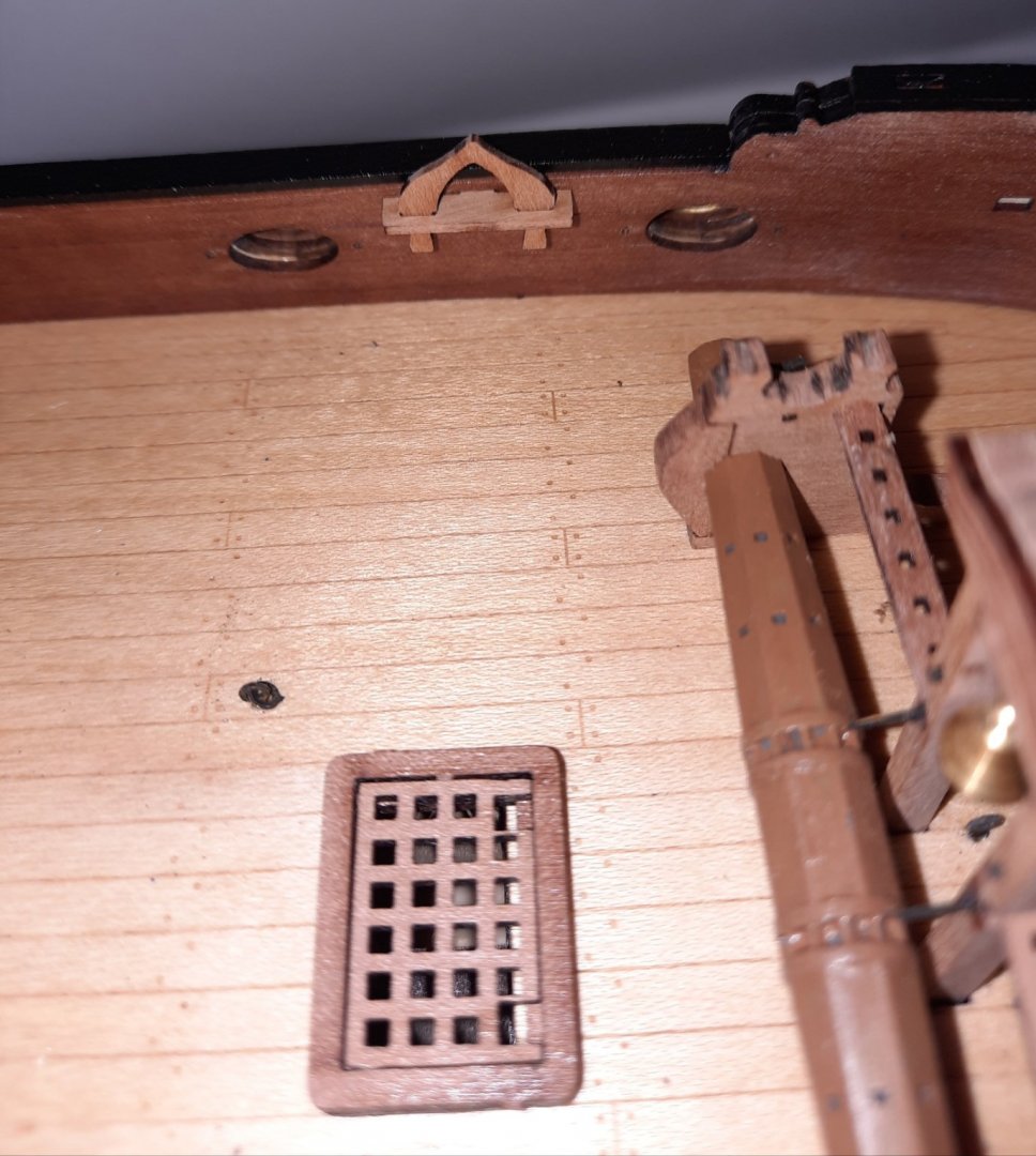
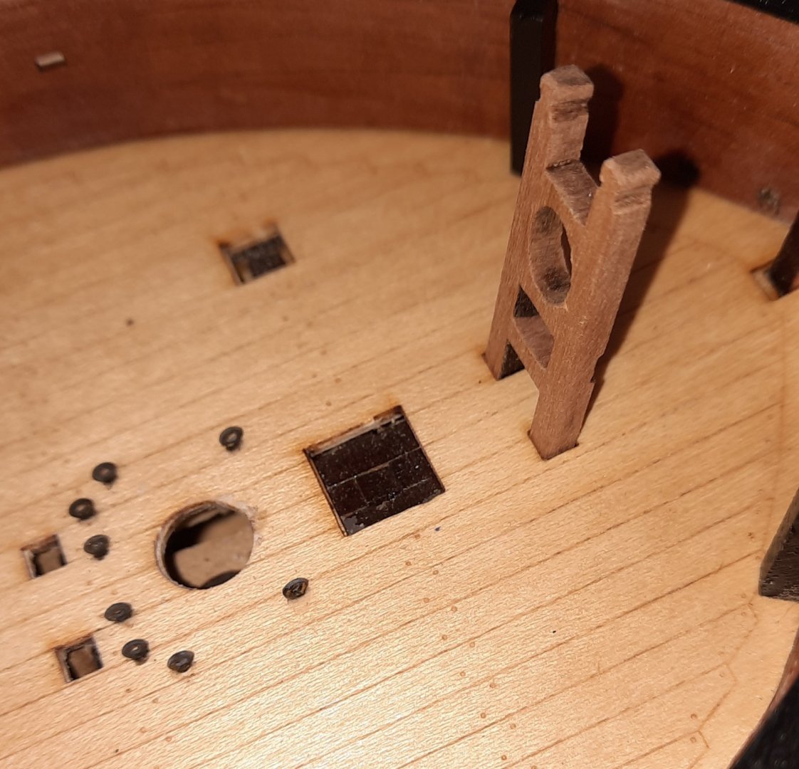
The inner bulwarks are provided with locating holes for the 4 off Staghorn Cleat Beam assemblies. I have test fitted all four of them and they were all a nice snug fit, as shown in the following picture which shows one of them dry fitted (upside down for the time being).
- GuntherMT, DelF, chris watton and 6 others
-
9
-
3 minutes ago, BobG said:
Great work and an outstanding build log as well!
Thanks Bob
-
-
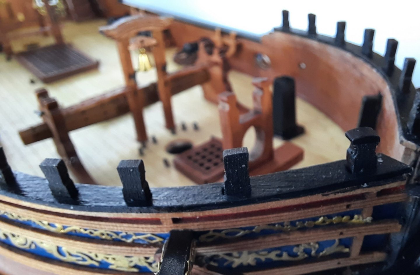
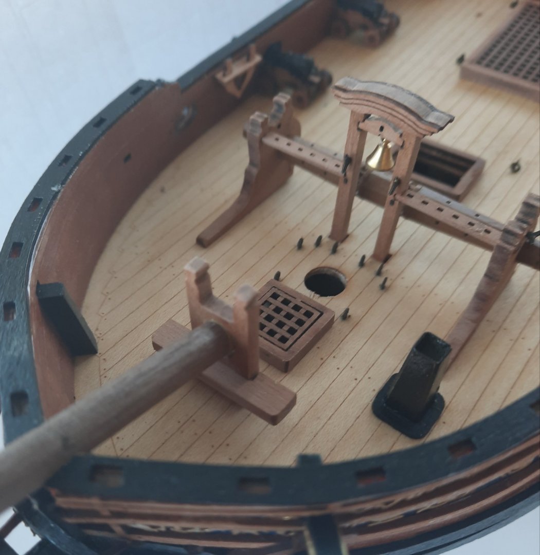
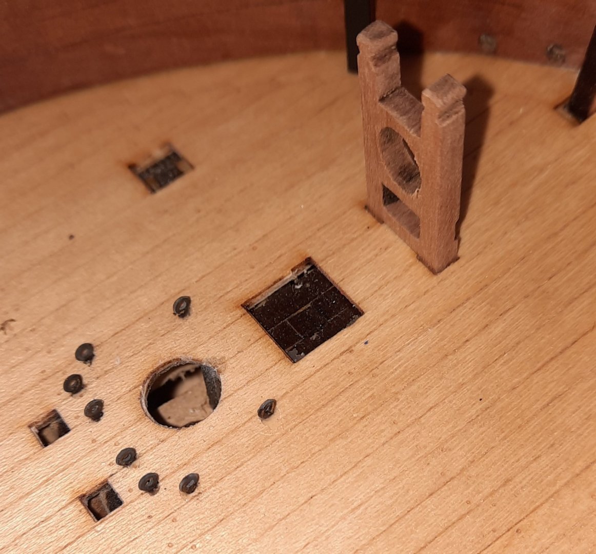
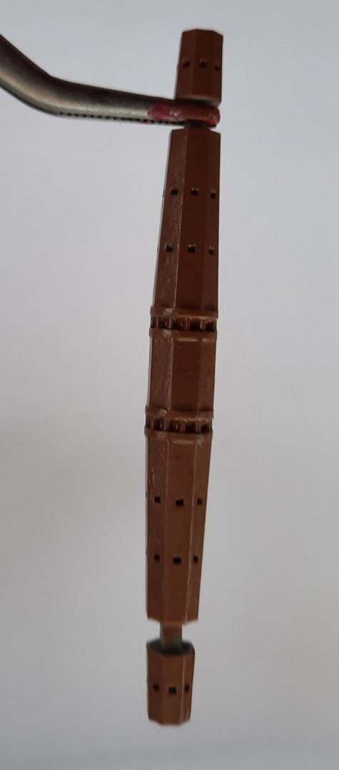
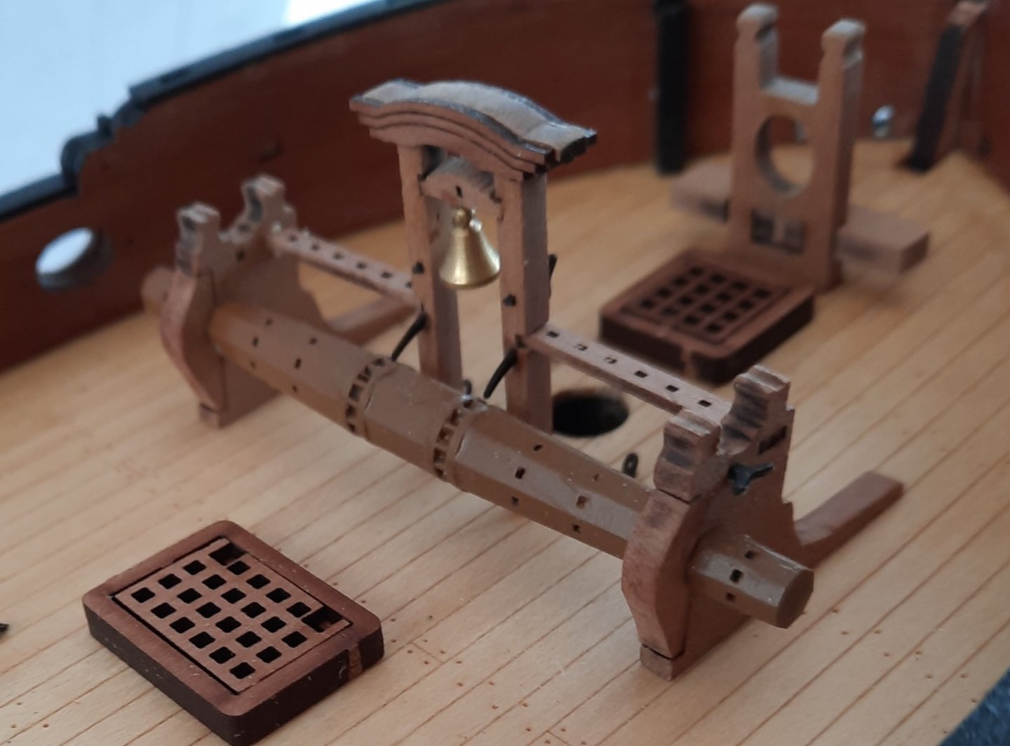
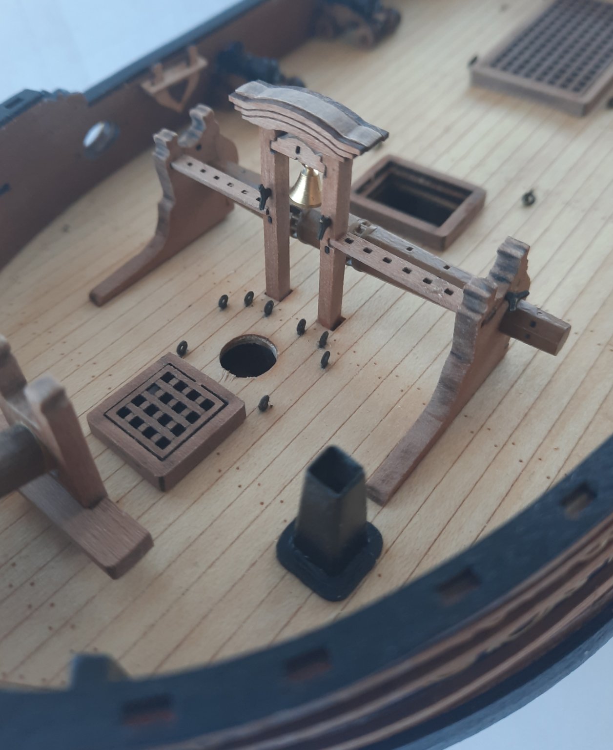
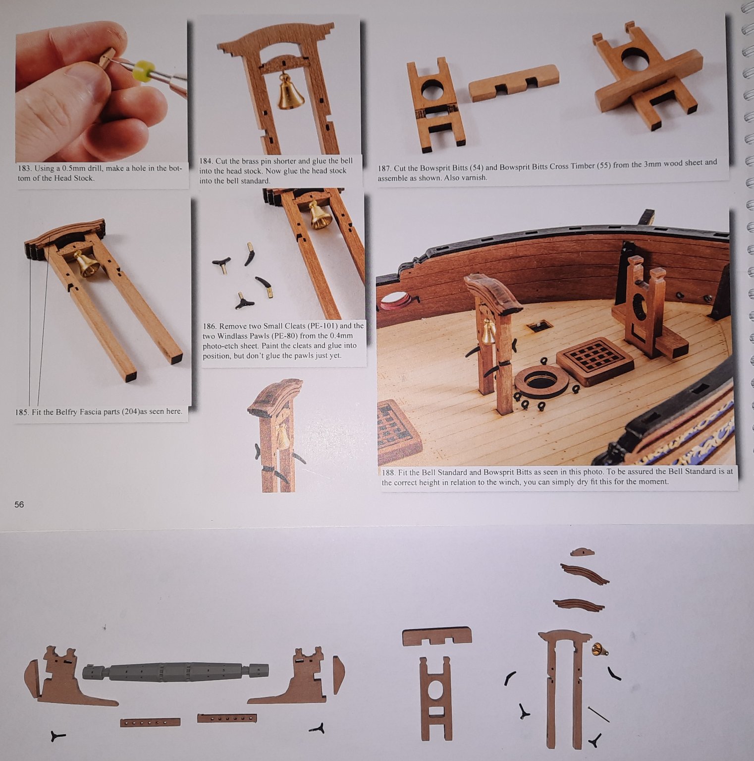
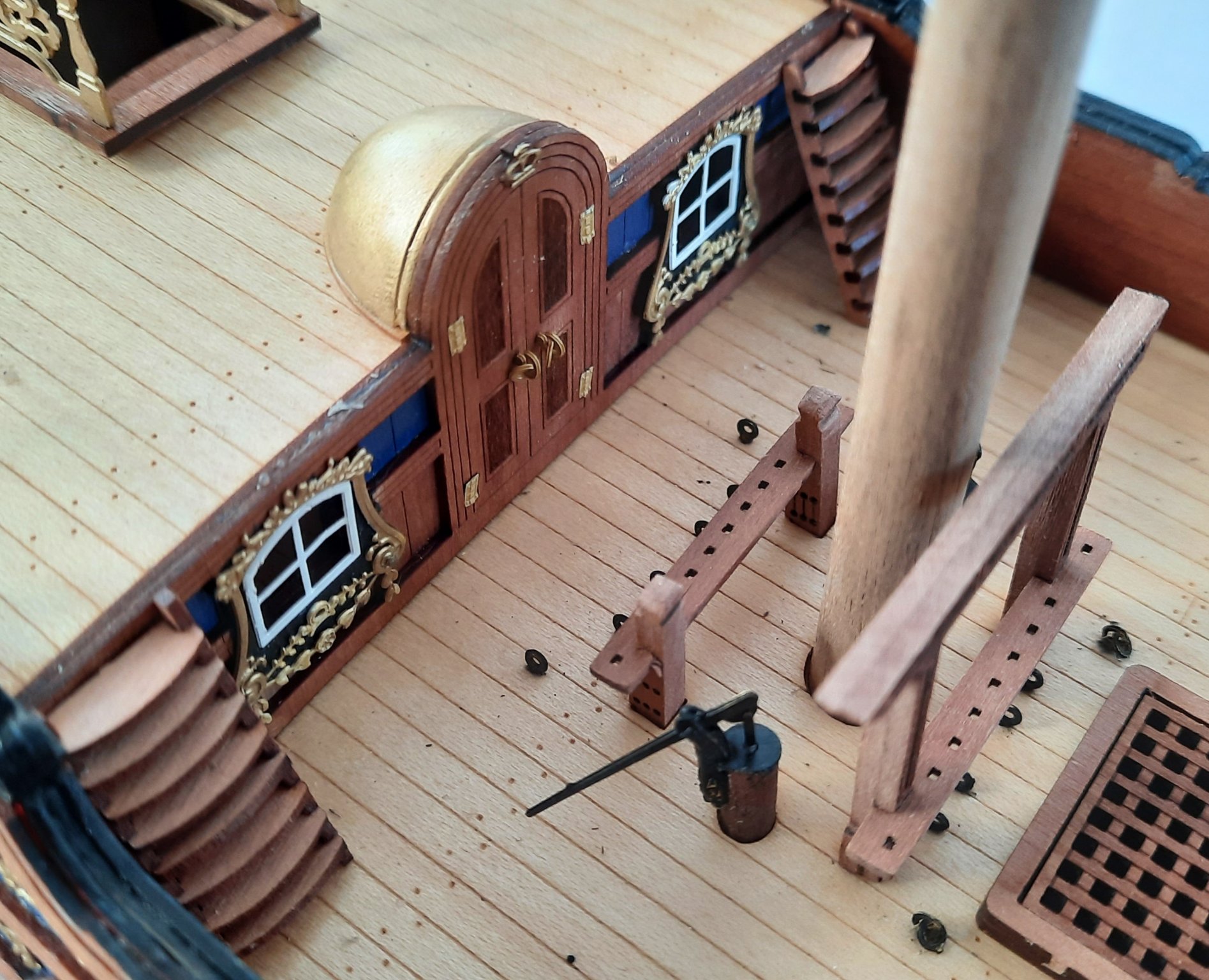
I thought today I would share some of my build methods in a bit more detail and I have focused on todays work which was the bowsprit bitt, ships bell and windlass assemblies.
Parts Check
Before I start any assembly I ensure I have all the parts. I also refer to the build instructions / photos for additional guidance. The picture below shows this.

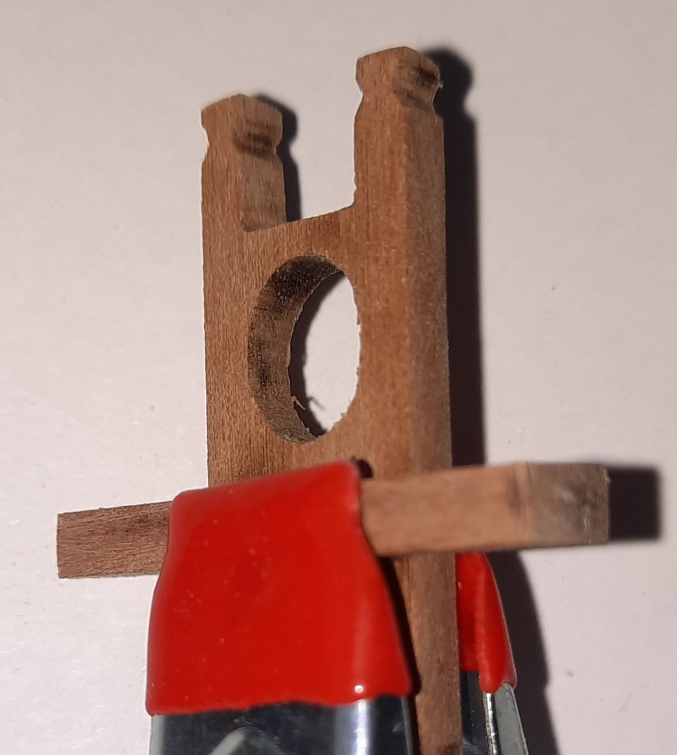
Bowsprit Bitt Assembly
I started by removing the laser char from the two parts. I also rounded off the square tops. Once that once done I did a test fit of the bitt in the locating holes on the deck. In this instance, as seen in the photo below, the bitt did not locate fully.
I did not wish to force the part in the holes and risk damaging the bitt. On closer examination I noticed that there was a very tiny slither of the base beneath the deck which was causing the problem. I took my square file and filed away the excess. After a few minutes I retried and this time it was a perfect fit.
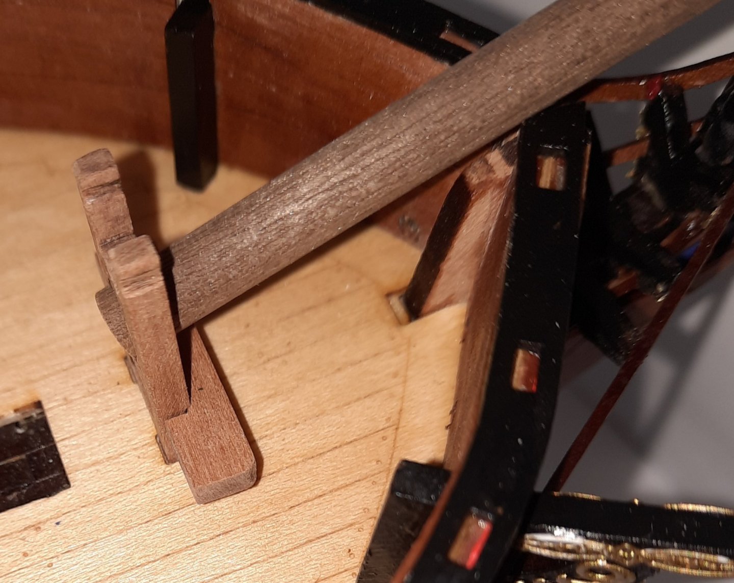
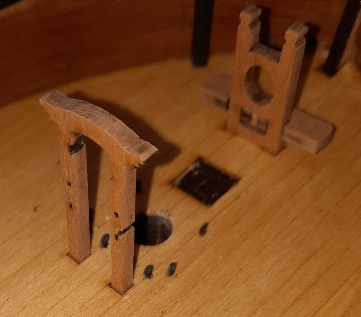
Now that I was happy with the installation aspect I checked the fit of the cross member timber. As there was no fitting issues I applied some wood glue to the contact surfaces and held the parts together with a clamp for a few minutes.
The completed assembly was then dry fitted in place with a length of 6mm dowel inserted to check the bowsprit would locate correctly, which it did.
Ship's Bell
Once I had removed the laser char from the ship's bell support frame I did a test fit and found that the part located perfectly first time.
Next I moved on the the ship's bell. I placed a brass pin through the hole at the top of the bell, using a touch of ca gel to secure it in place. The pin was then bent to 90 degree angle. I drilled a 0.5mm hole in the headstock and glued the bell in place.
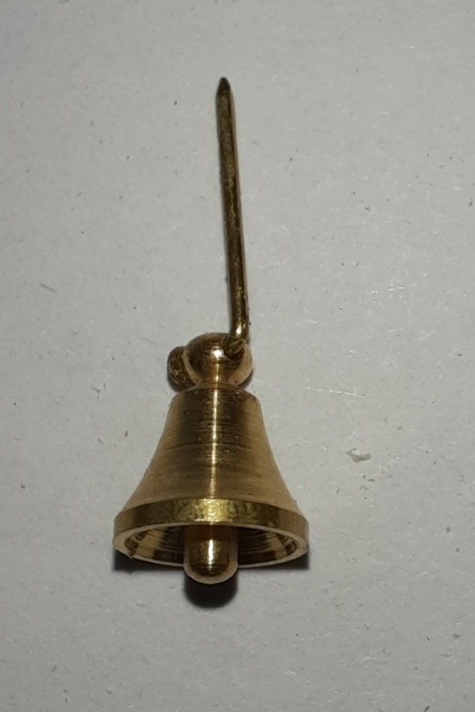
The pin showing in the headstock opening has been removed.
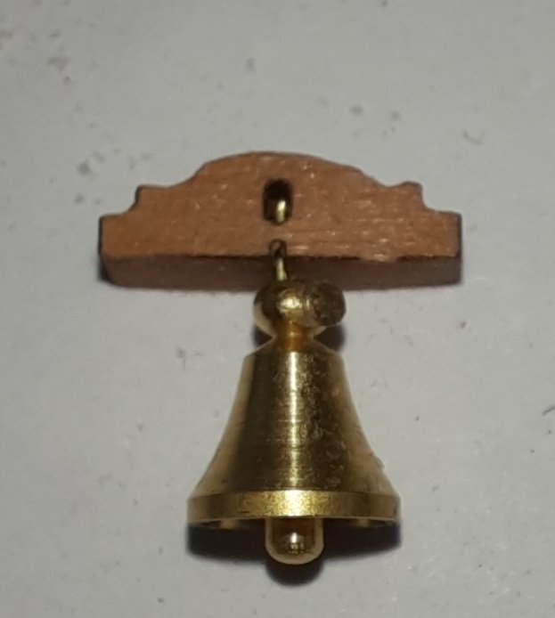
Once that was done the head stock, fascia panels, cleats and windlass pawls were added. I did blackened the cleats and windlass pawls prior to installation.
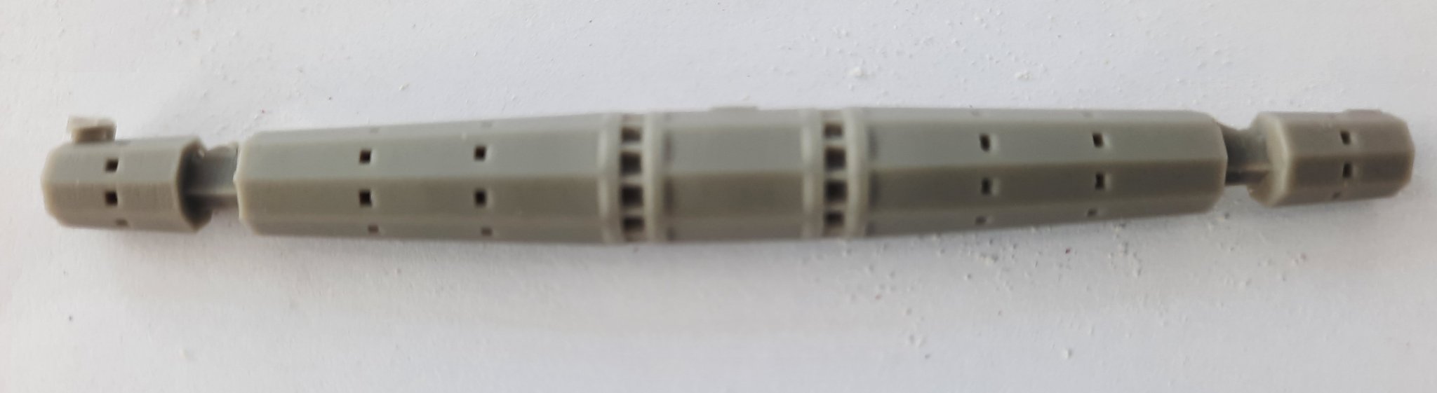
Windlass
There was some excess bits of resin on the octagonal winch drum supplied with the kit, as can be seen in the next photo.

Using a craft knife I very carefully removed the excess material and tried a test fit with the winch drum. No problems were detected.
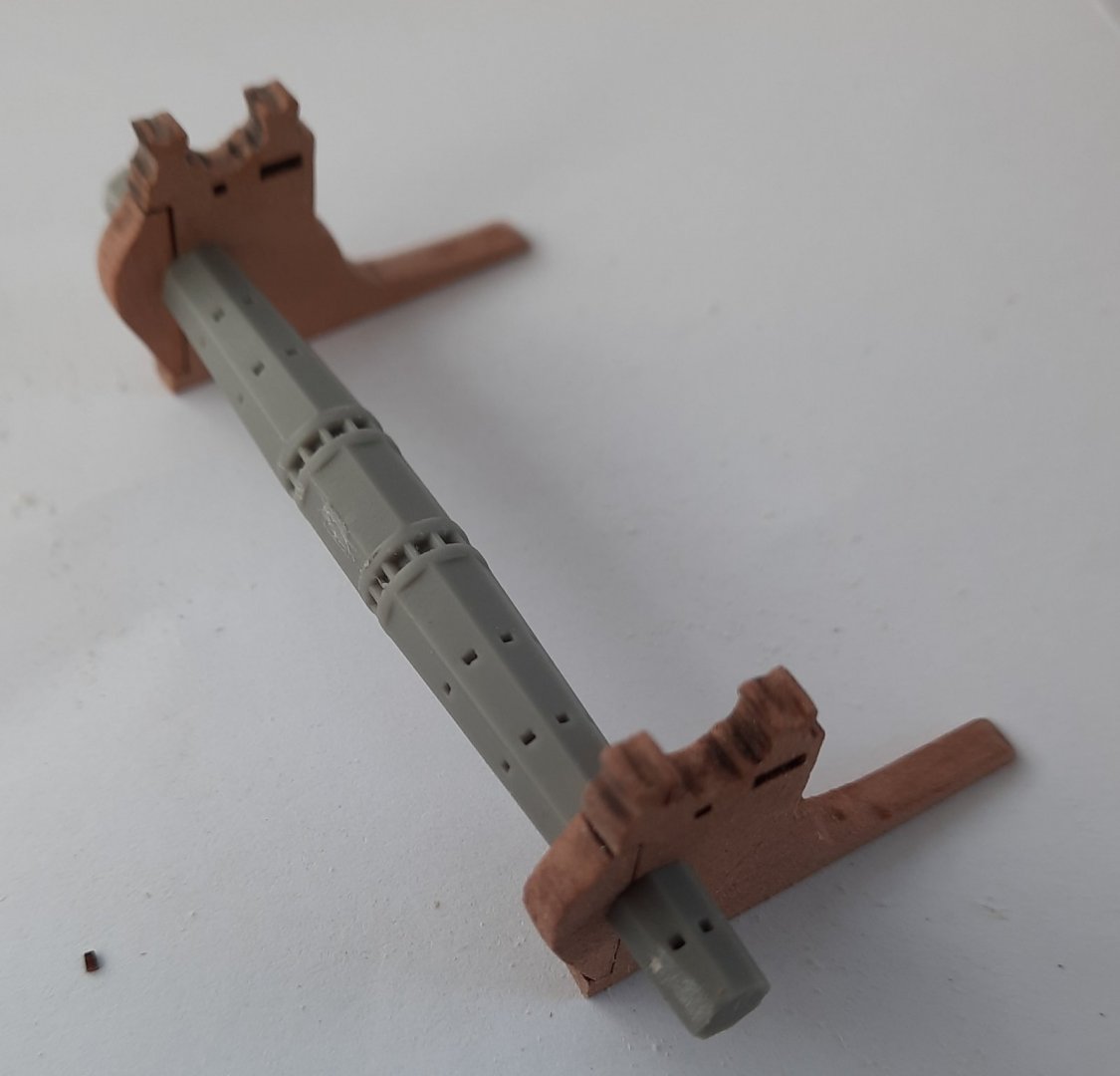
I then applied a couple of coats of walnut paint to the octangle winch drum.
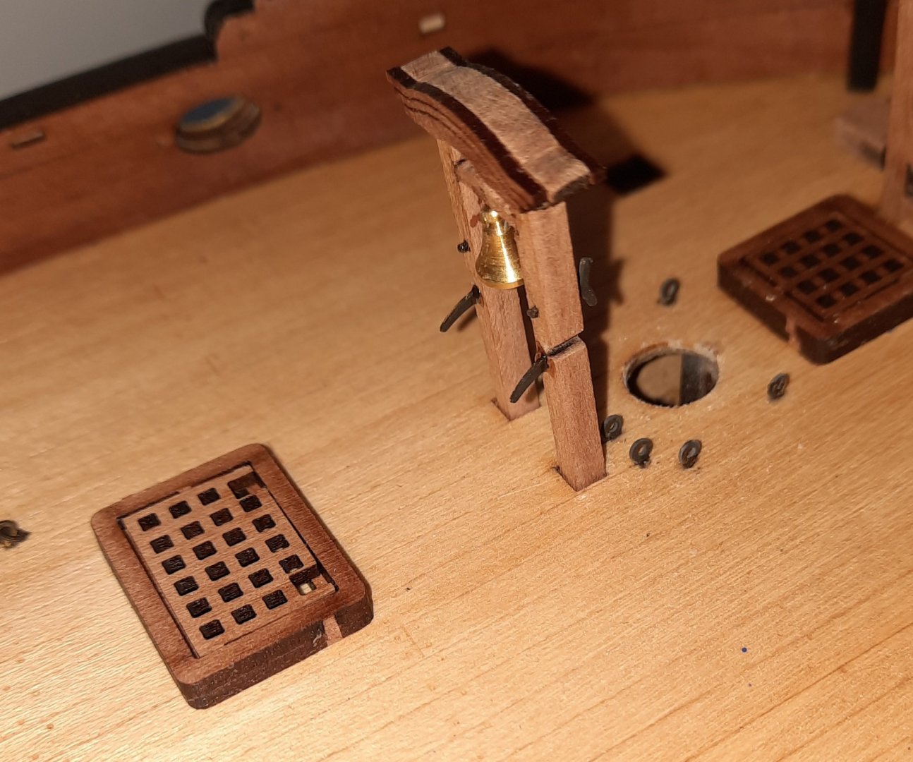
It was then a simple task to glue the various bits together. The two windlass belaying rails also locate in slots provided on the ship's bell support frame. Therefore when I was gluing the rails in place used the ship's bell assembly to set the rails position correctly.
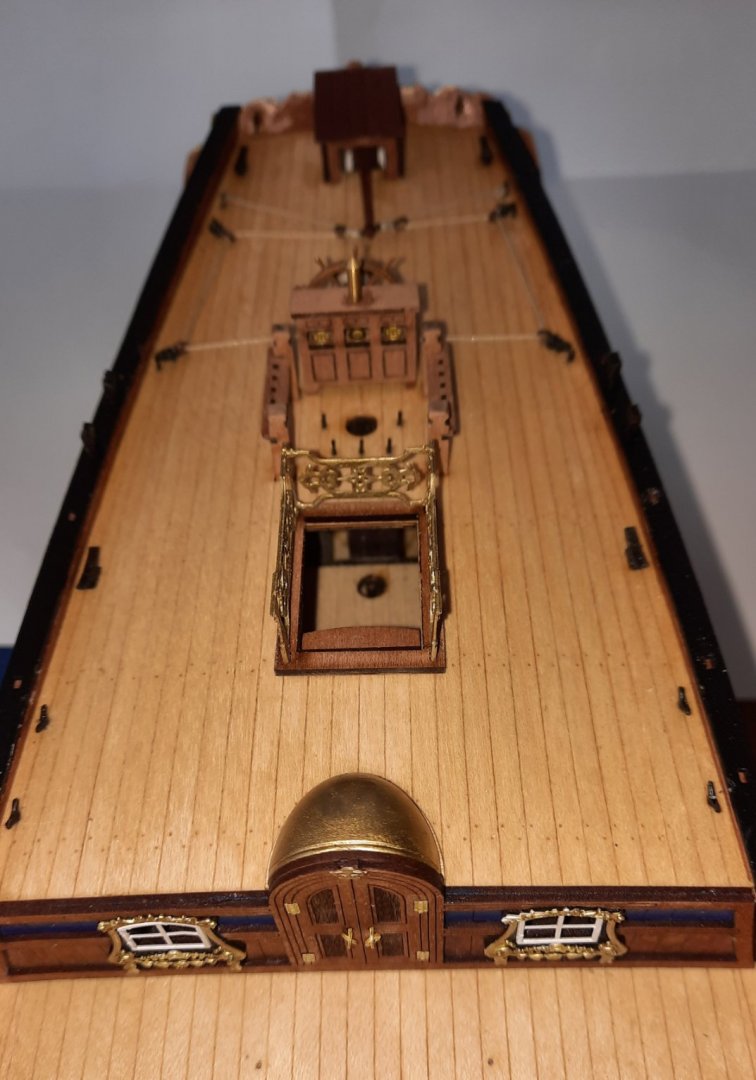
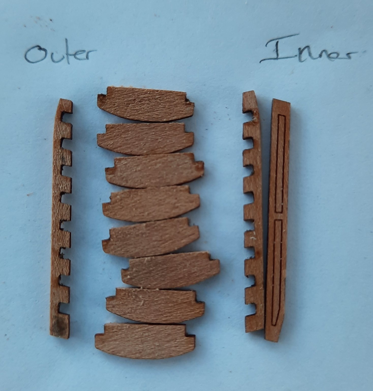
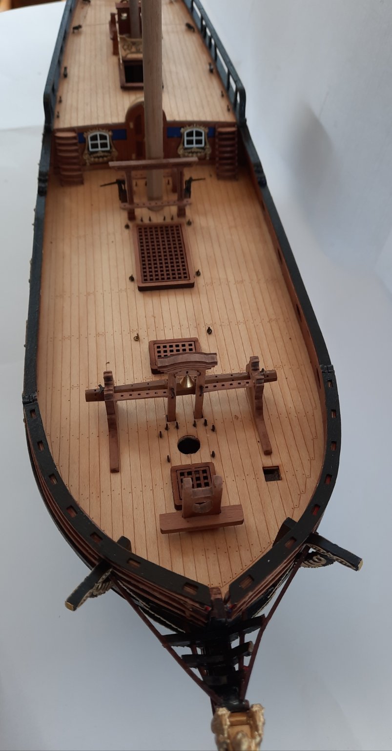
Main Deck Steps
I also assembled the two main deck staircases today. This was a bit fiddly. There is an inner and outer rail for each set of steps which you do need to consider when assembling. I did make a small pencil mark on the two outer rails which helped me greatly.

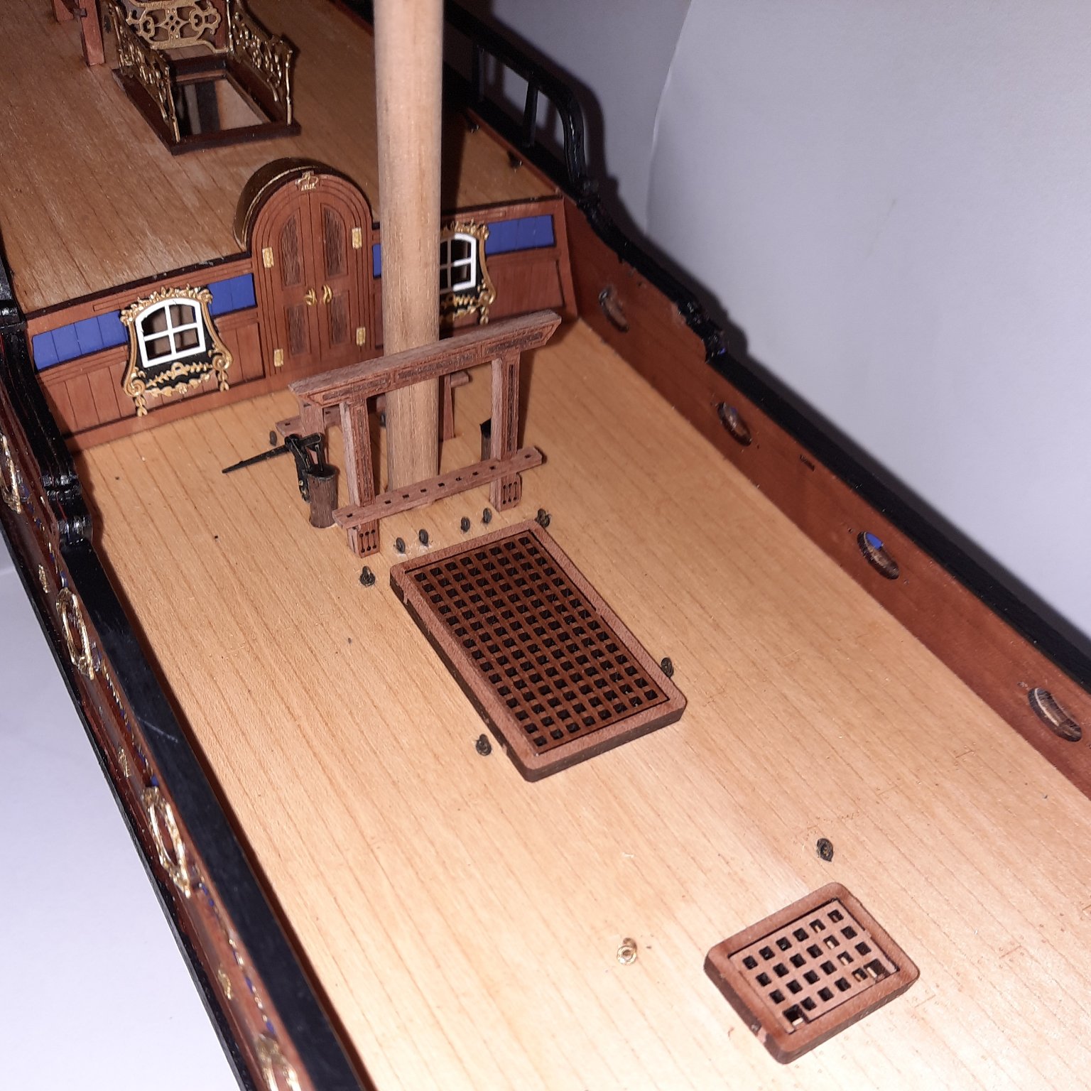
The final picture is of the main deck. All the deck items are dry fitted for the time being.
-
-
8 minutes ago, rafine said:
Really well done Glenn. She looks great.
Bob
Thanks Bob, I am just pondering if I should rig the 6 cannons. Any thoughts?
-
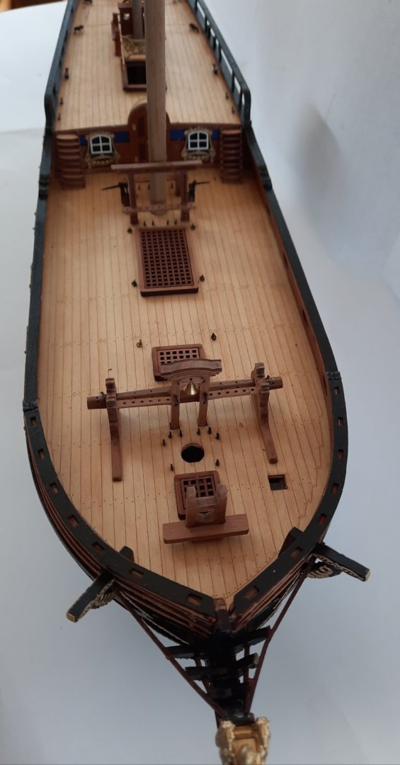
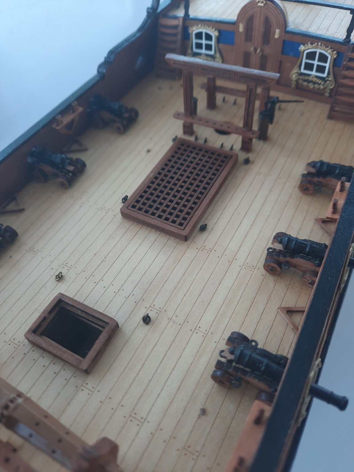
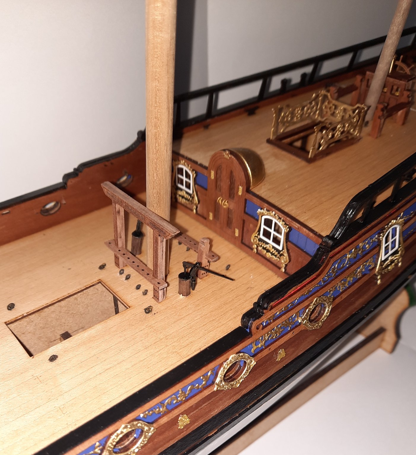
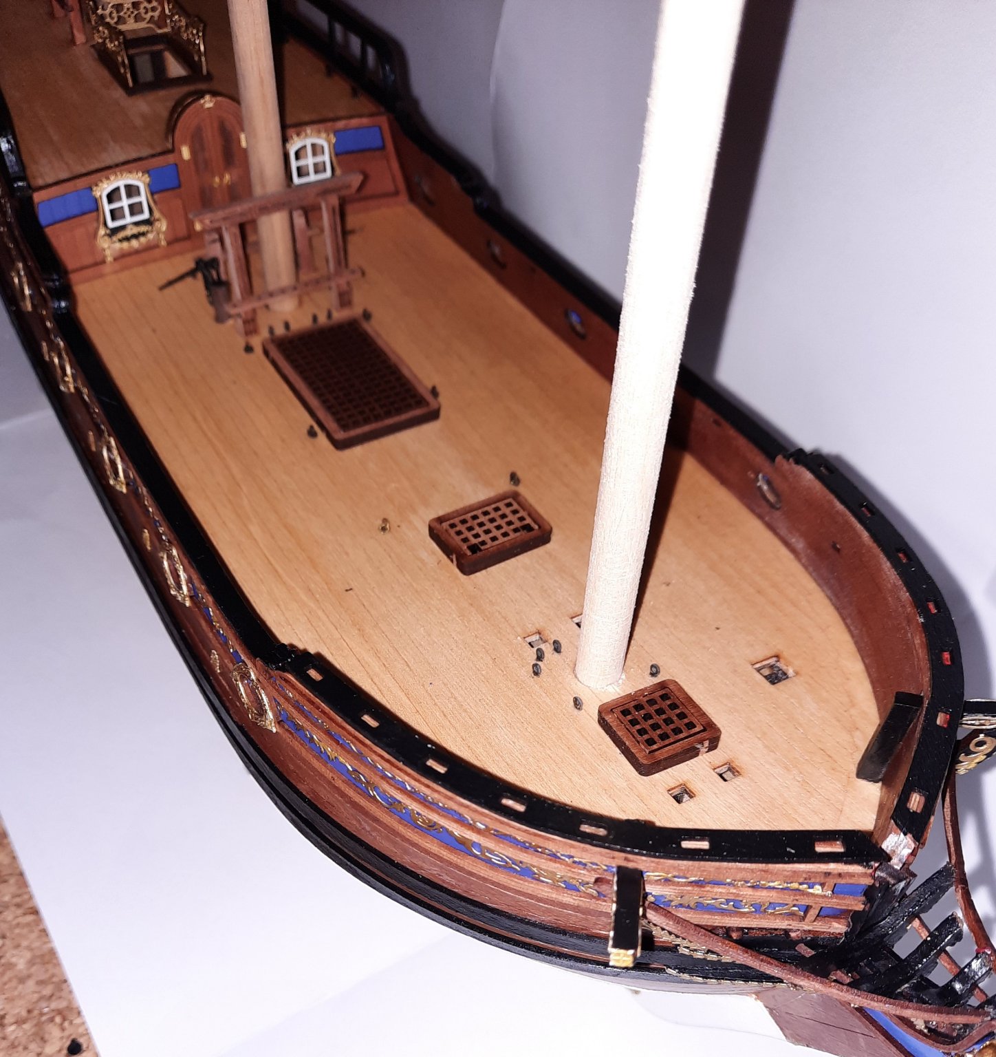
I have had a very productive day in the shipyard as can be seen in the following photos.
Test Fit Of Mast Dowels
I decided to insert some dowels (of the correct diameter) in the mast holes as can be seen in the photos. I have not used all the kit supplied dowels as I had a spare length of 8mm dowel which I used for the foremast test fit.
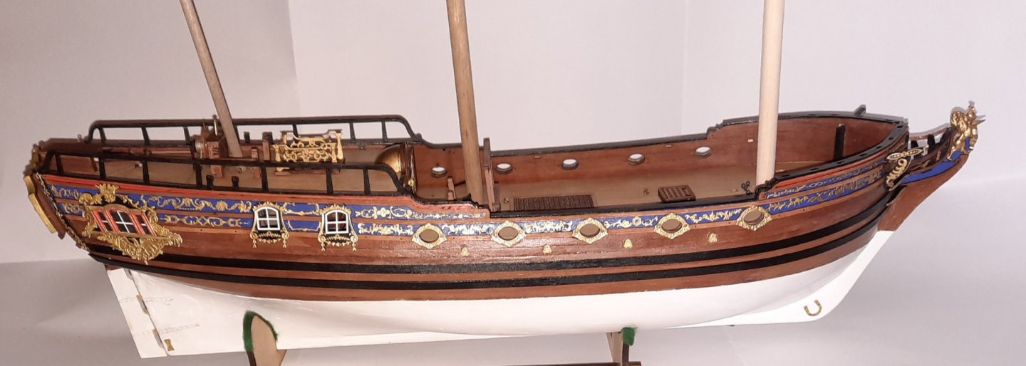
There is a very nice looking rake to the mizzen mast.

Aft Rail
If I was to tackle fitting the aft rail again I would not paint and varnish the capping rail prior to fitting the aft rail as the paint and varnish applied did close up the aft rail locating holes. I was able to correct this by filing the aft rail fitting tabs so they would locate. Take care as the aft rail pillars are very fragile and easy to snap off.
Eyebolts
I then moved on to fitting the eyebolts to the main deck. The method I used for this task was:
a) run a 0.6mm micro drill through all the eyebolt locating holes.
b) test fit an eyebolt in each locating hole
c) put a touch of ca gel on the eyebolt stem and insert fully, ensuring the eyebolt is correctly aligned.

Bits and Bilge Pumps
I then assembled the Main Mast Gallows and Main Mast bits. I removed the laser char and rounded the tops on the main. I then moved on to building the two bilge pumps. In the manual the 4mm dowel required for the bilge pumps needs to be cut to approx. 30mm. I was pretty happy with my dowels, as can be seen in the following photo.
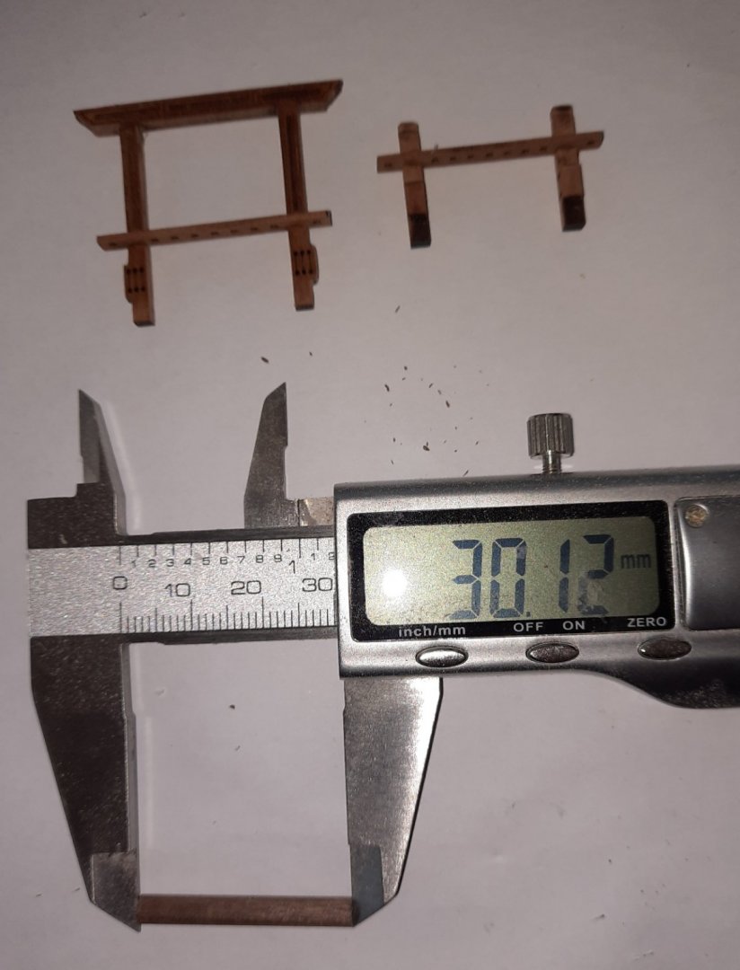
The items are only dry fitted on the deck for the time being.

Deck Hatches
I then assembled the 3 main deck hatches. The hatches are only dry fitted on the deck for the time being.


- Edwardkenway, GuntherMT, p.hoek and 8 others
-
11
-
Really nice job, it looks amazing.
- FrankWouts, Rustyj and chris watton
-
3
-
4 hours ago, Rustyj said:
She's looking great Glenn!
Thanks Rusty
-
53 minutes ago, DelF said:
I agree with Darrel - she's coming along very well.
Many thanks Derek.
I have now fitted the aft rails. Be warned fellow builders they are very fragile and very fiddley to fit.
- chris watton and Rustyj
-
2
-
5 minutes ago, DWright said:
Sensational job on the aft deck Glenn. Even under the telling eye of the camera she looks perfect. Your whole log has been inspirational with great instructional hints. Thank you.
Now it's time for me to get back to work. I've been AWOL too long.
Darrel
Hello Darrel
I am glad you are finding my build log helpful. I class myself as an enthusiastic amateur. I have found my building skills have improved from following advice I have found on other peoples logs.
-
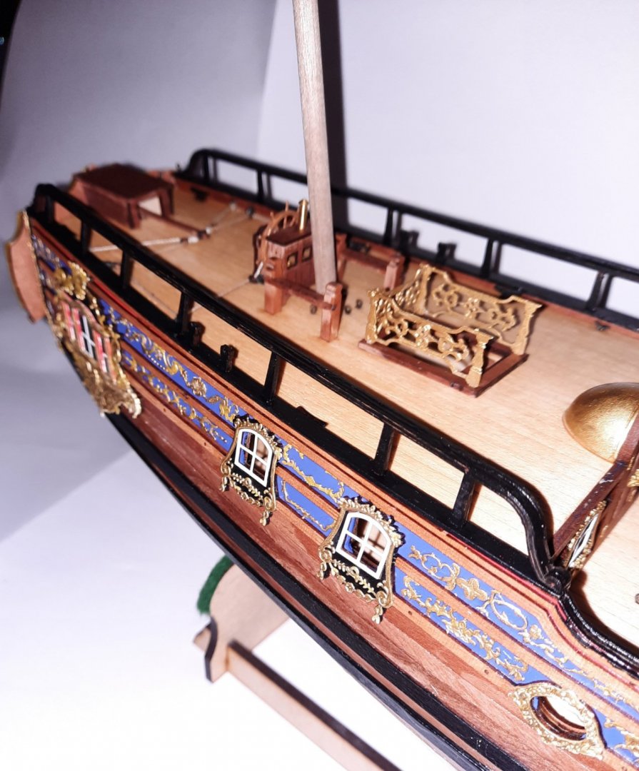
The upper aft rail has been assembled and I am currently waiting for the glue to fully cure. Please be aware the aft rails are very delicate. I have managed to snap off one of the support beams. It is not a major issue as it can be fixed very easily.
In the meantime I have now added all the items to the upper deck, including all the cleats and eye bolts, excluding the belay pins for the mizzen bitts, which I will fit during the rigging phase. I have now started work on building the various items required for the main deck, which should keep be busy for a few days.
I did prime and paint the spiral staircase PE rails gold.
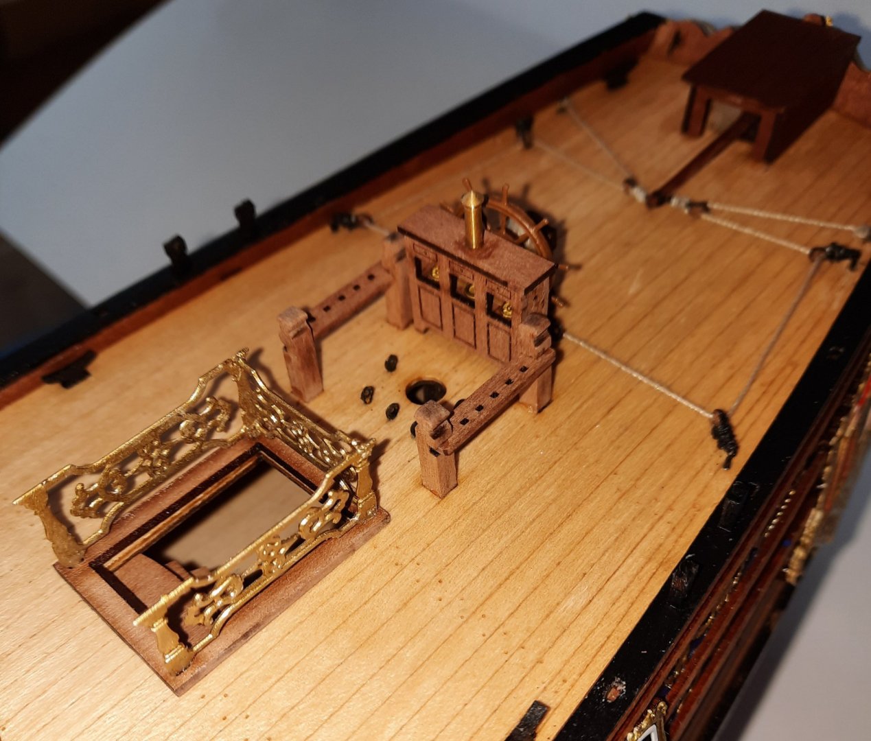
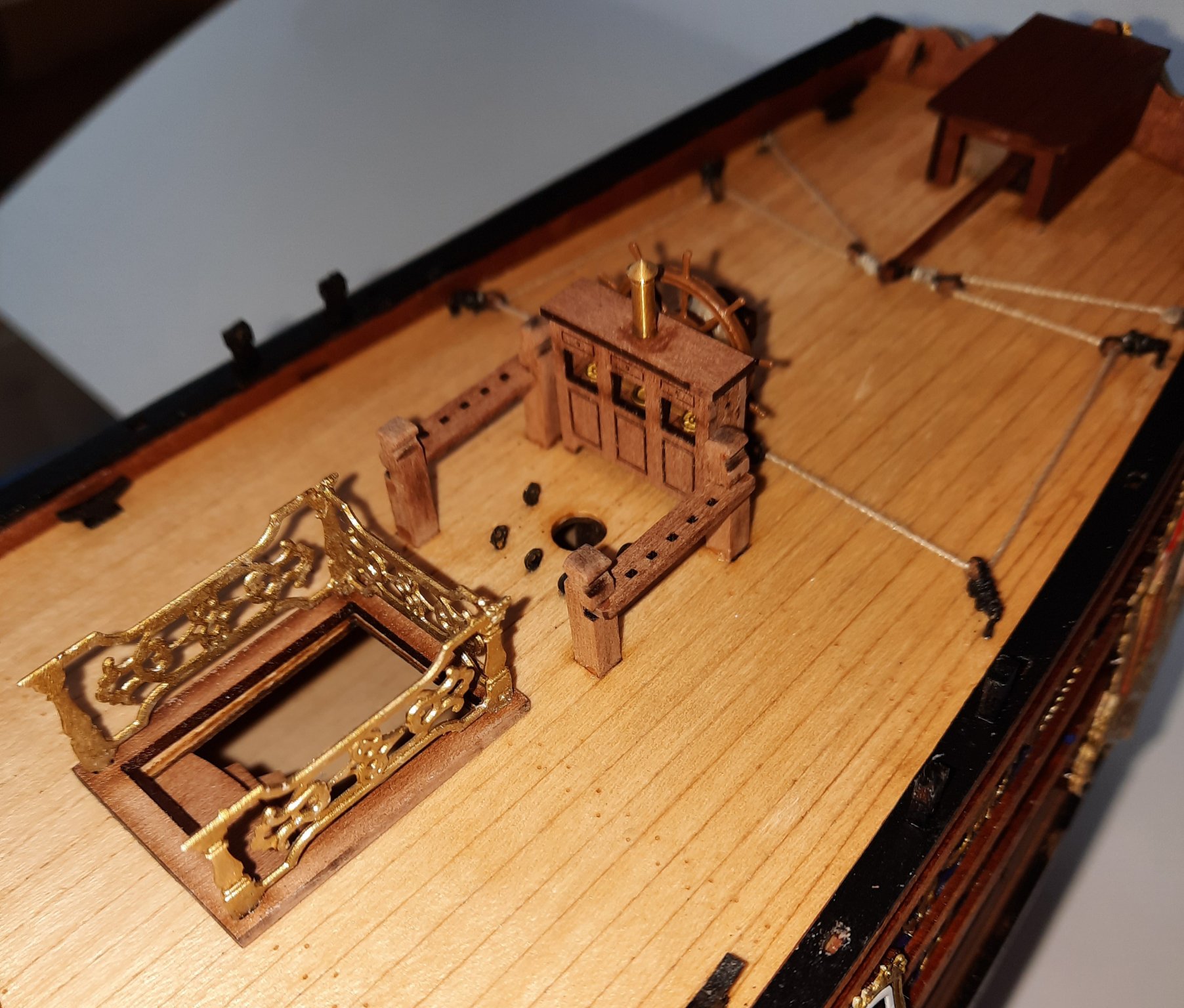
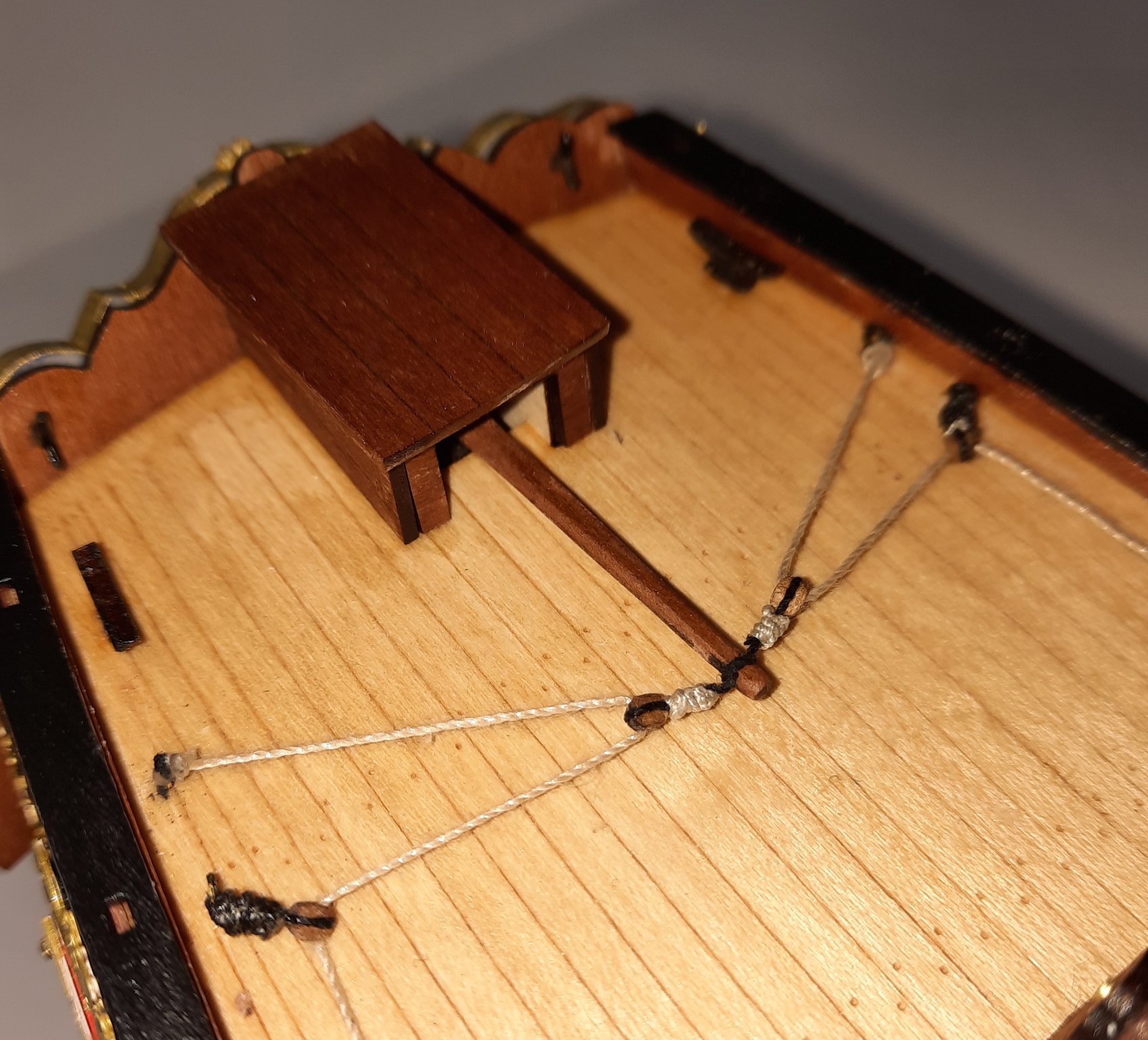
The tiller housing

Binnacle, mizzen bitts and spiral staircase.
- Matt D, DelF, Ryland Craze and 8 others
-
11


Duchess of Kingston 1798 by glennard2523 - FINISHED - Vanguard Models - 1:64 - Royal Yacht by Glenn Shelton
in - Kit build logs for subjects built from 1751 - 1800
Posted · Edited by glennard2523
I have now started work on the masts and yards. My bench saw is out for delivery and is expected to arrive later this afternoon.
I have started work on the bowsprit and jibboom. The bowsprit requires a 6mm dowel. In order to help aligning the various parts to be fitted I start with a centre line. I simply clamp a 3mm wood strip to the dowel and then I can draw a line along the entire length.
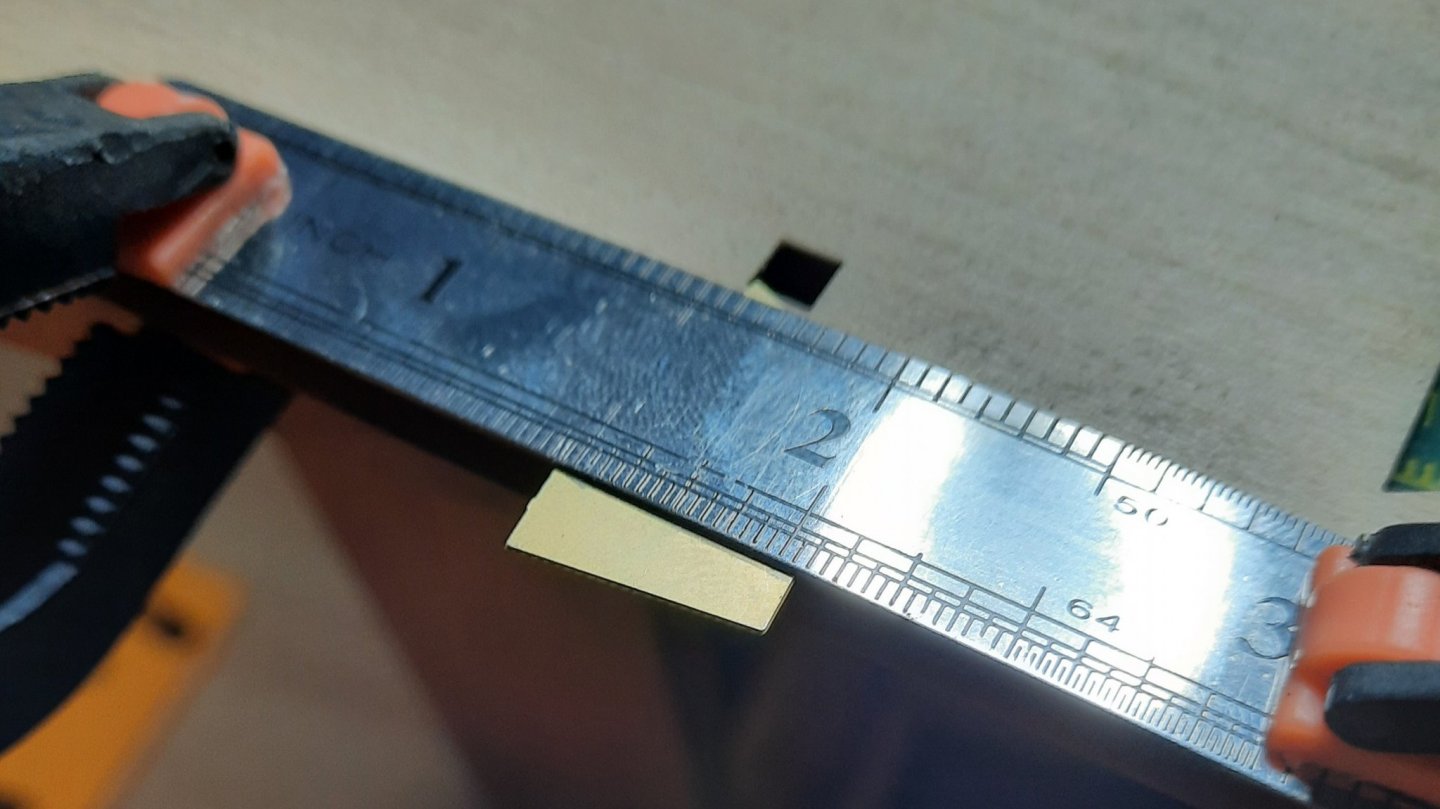
As I will use the bench saw to make the angled end cuts I moved on to making the jibboom. This requires a 115mm long 3mm dowel which tapers to 2mm. I like to identify key points along the length. The first 35mm will not be tapered, so the 3mm to 2mm taper will be applied to the final 80mm. To get a good taper the diameter need to reduce by 0.25mm per 20mm. I have used some very thin tape to mark the dowel.
I like to mark it slightly long
The dowel was then placed in my lathe and tapered using sandpaper. I started with 100 grit and then reduced to 320 grit. It took me around 10 mins to get the required taper. I kept checking the taper at the 20, 40, 60 and 80mm points.
There is a grove required near the end. I made this using a folded edge of sandpaper while the dowel was still in the lathe. The completed dowel was then given a light sand with a 800 grit sandpaper. The end result is a nice looking jibboom the matches the plan drawing
I think I got this measurement pretty close!