


Glenn-UK
-
Posts
2,666 -
Joined
-
Last visited
Content Type
Profiles
Forums
Gallery
Events
Posts posted by Glenn-UK
-
-
3 minutes ago, dzerbato said:
Nice work. Your build is certainly making me eager to start my Speedy.
It is a great design which I'm sure you will enjoy building. I always think adding the deck fittings really starts brings the build to life.
-
Thanks Derek. It has been a very productive day. I will start the mass production the swivel gun assemblies later this week. I have tended to paint the parts before removing from the sheets, and then touching up where necessary.
-
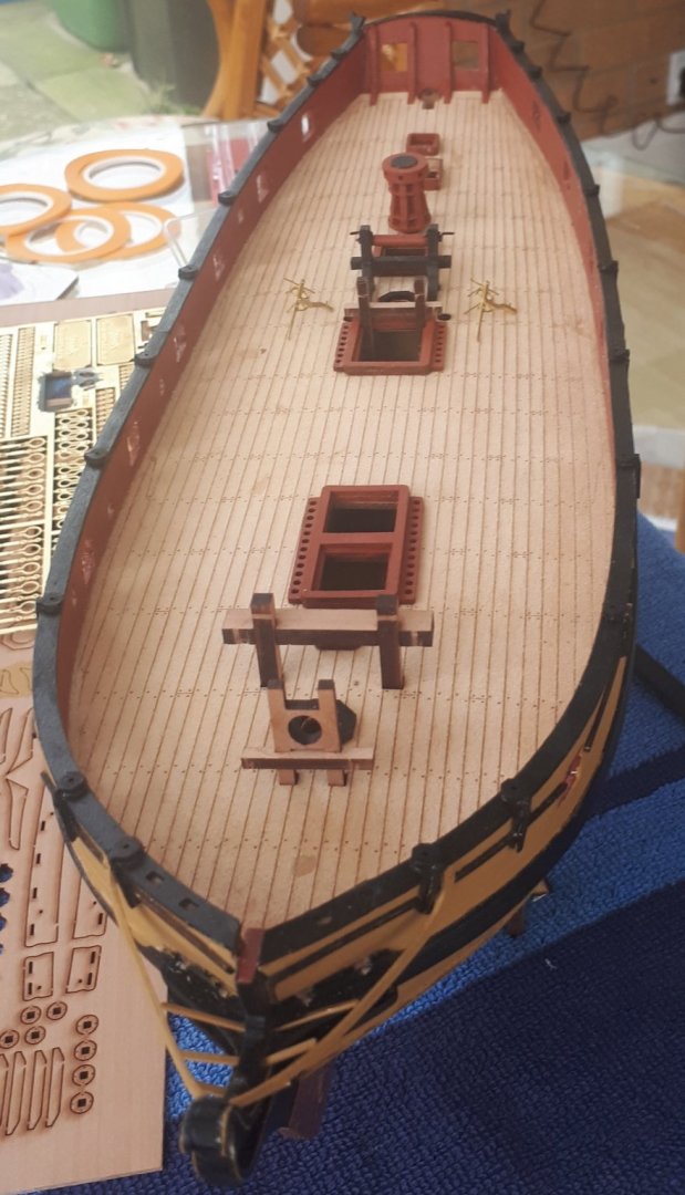
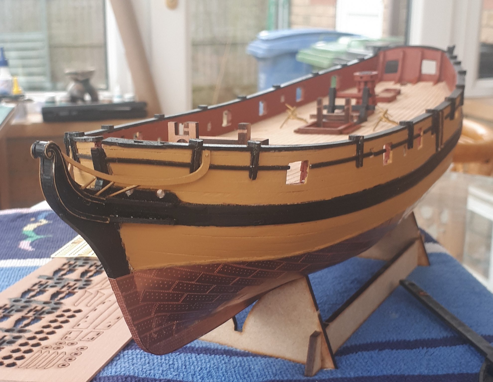
I have fitted the bow main rails and the three bow vertical rails, some of the photos were take before the vertical rails and been attached to the main rails.
I would say that this was the most difficult task to date with this build, it took a while to find the best methods for painting and then fixing parts to the hull. I ended up pinning the main bow rail to the hull, noting the pin will be hidden once the catheads have been installed.
I have built and painted the catheads and they will be glued in place tomorrow. I have also assembled the majority of deck items and placed in position (not glued). The two deck pumps (shown on the photos) just need to be painted and fitted to 4mm x 40mm dowels.
The 4lb cannons can be seen in the first photo, on the window ledge.


- egkb, KARAVOKIRIS, GrandpaPhil and 4 others
-
 7
7
-
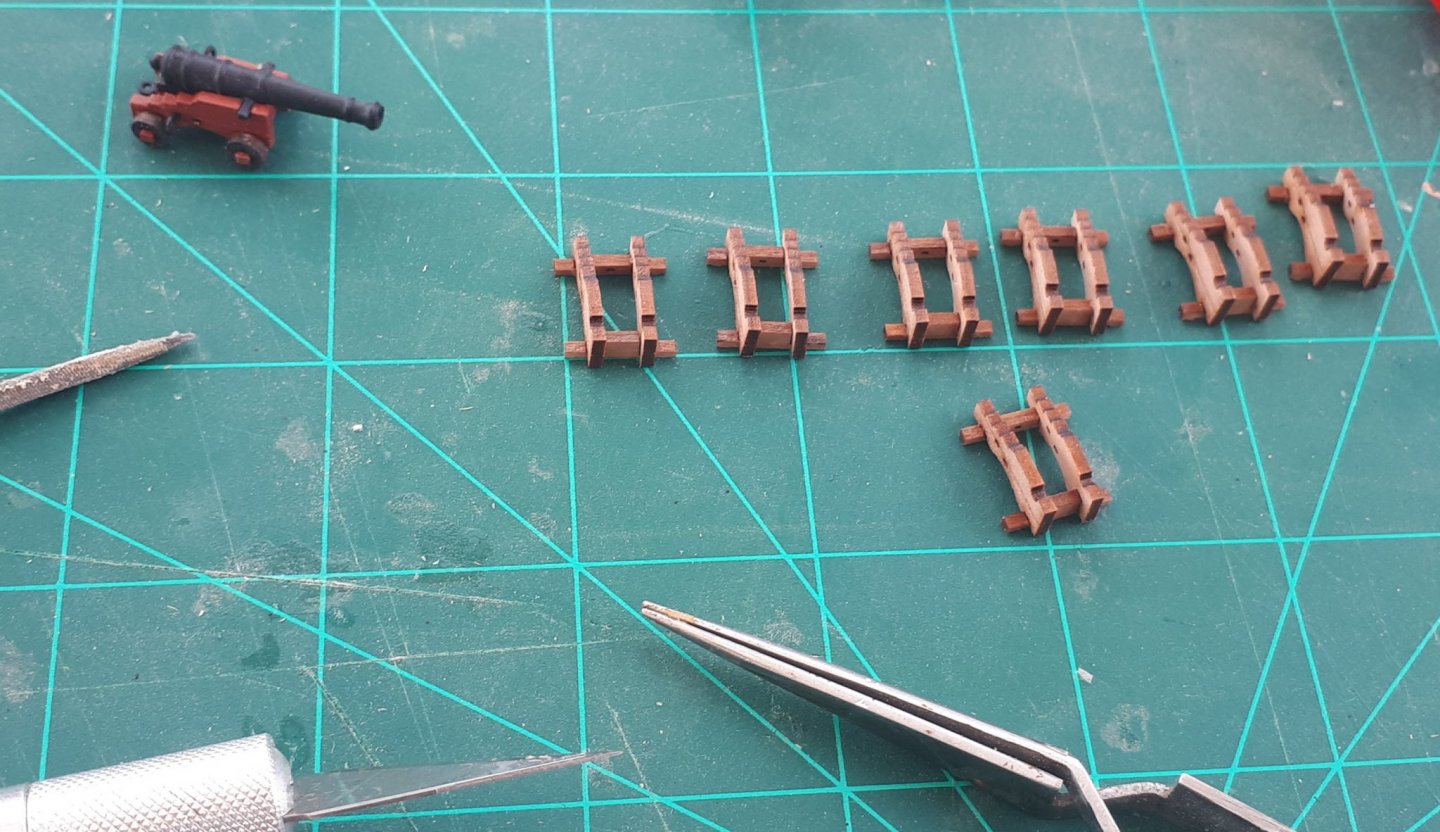
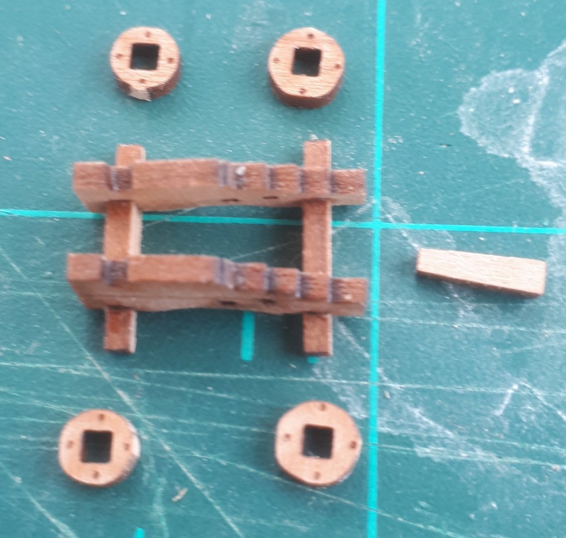
Here is an update of my progress. The first two pictures show the swivel gun bases (unpainted) fitted to the capping

The next couple of pictures show the swivel gun bases painted black
I initially painted the swivel gun post supports yellow, but as I had incorrectly positioned them I was not happy with the results as shown in the following picture
.thumb.jpg.5d61856f4d080721e23e8636967a91f9.jpg)
I added some wood filler to the gaps and then painted the gun post supports black. It looks better.
.thumb.jpg.c2d5f54bf74711e6742a001899988131.jpg)
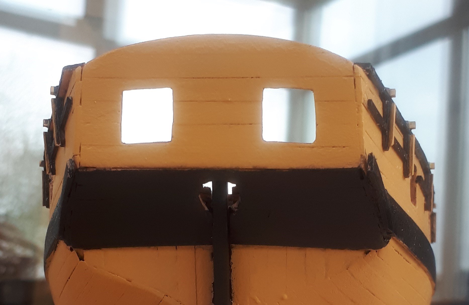
I have painted the stern area a mixture of yellow and black. I have filled in the hole on the bottom left of the picture

I have added the 3 off stern board rails, the stern capping and the 2 stern crutch boom patterns.
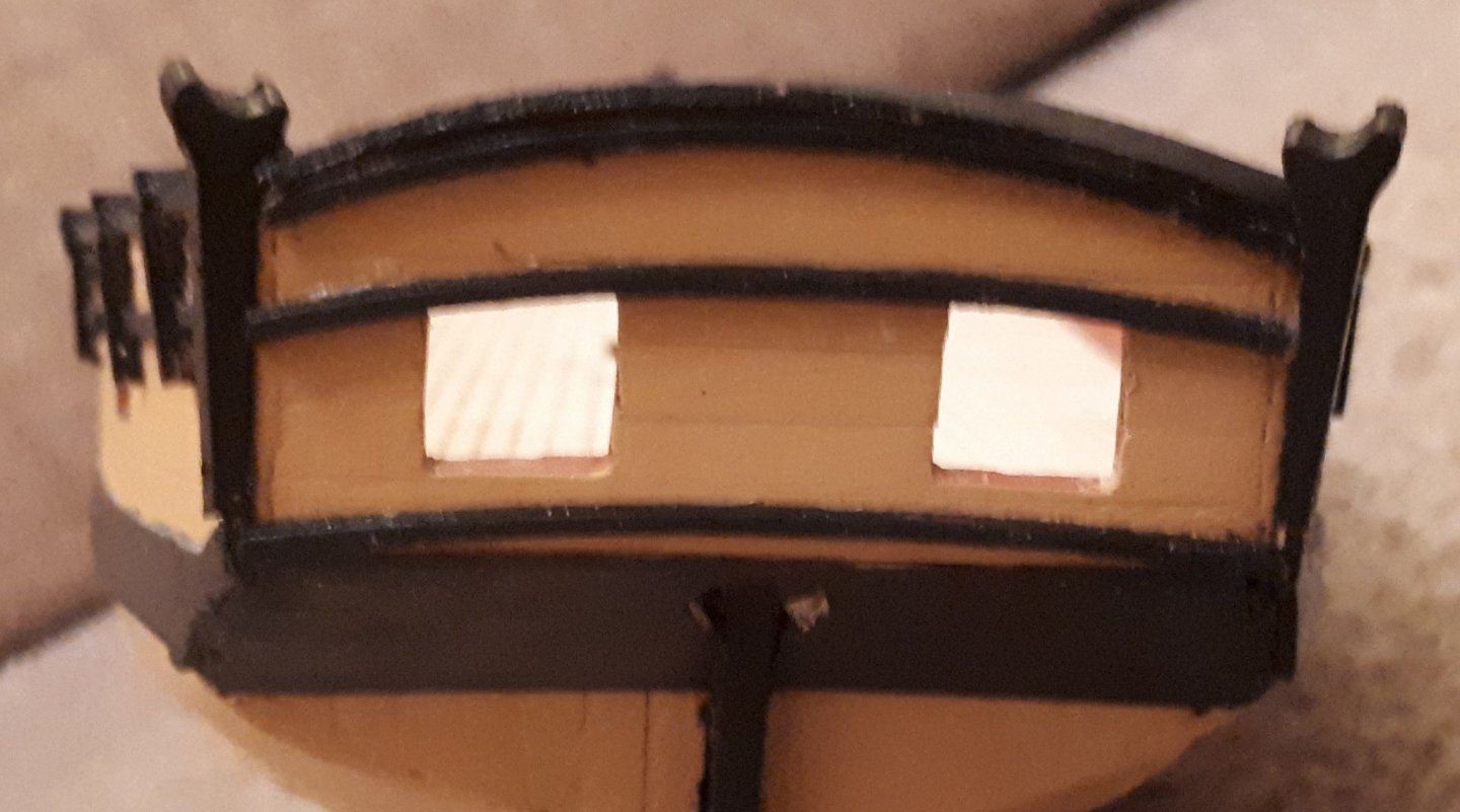
Finally I have checked the fitting of the 3 off bow frames. They all fitted OK. I have shown a picture with one bow frame in place during a test fit. The slots were tight and took some of the yellow paint of the bow strip. They will be repainted.
- chris watton, egkb, JpR62 and 3 others
-
6
-
I have now added the swivel post support timbers (painted yellow ochre) to the upper rail. Having read the manual for the next part of the build I have realised the swivel posts should sit flush with the top edge of the capping. I positioned mine to be level with lower edge of the capping. I probably could remove and reposition but I think I may leave them as fitted, in case I damage them.
I have also drilled the 4 off haswe holes using a 2mm drill.
Next up will be the fitting of the swivel gun bases to the capping.
I have just noted, looking at the photo below, a couple of copper plates with some ca glue which will need removing.

- VTHokiEE, Edwardkenway, egkb and 4 others
-
7
-
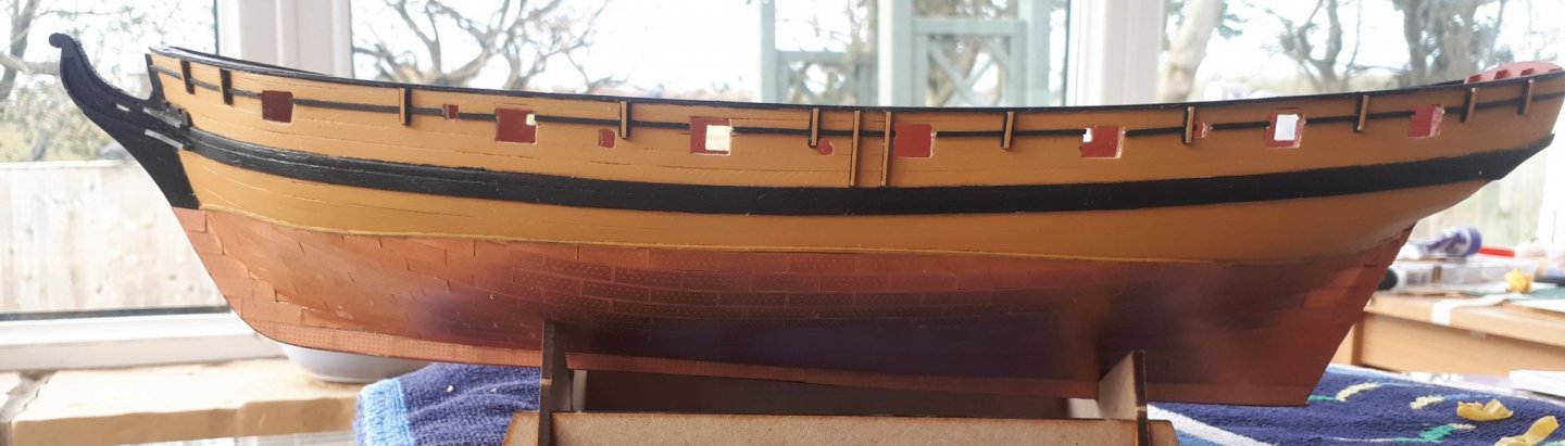
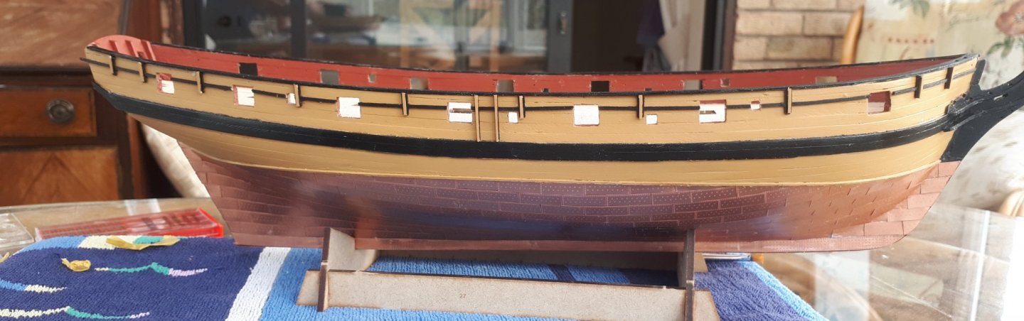
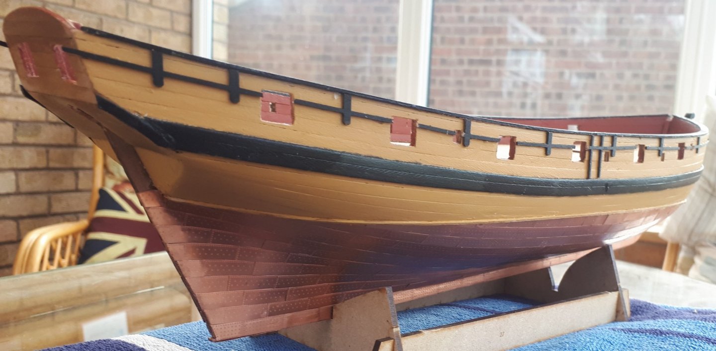
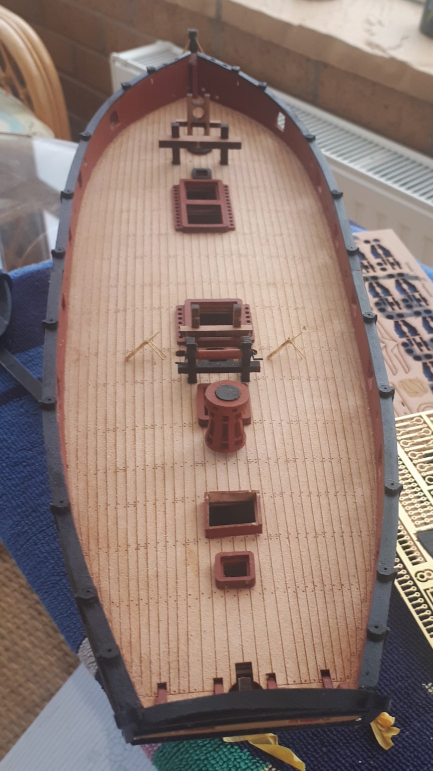
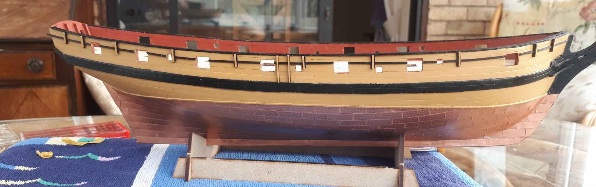
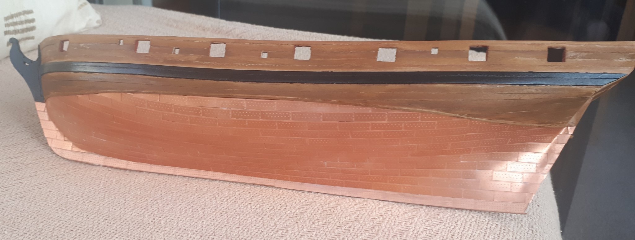
I was not totally happy with the natural wood finish of the hull above the copper plates so I applied an oak wood stain but was still not happy so I decided to paint the hull using my yellow ochre paint. I think it looks better now.
I have also added the capping rail and upper support rails and the decoration looks really nice. I have already painted the fender patterns yellow ochre and I will fix them to the upper rail patterns in due course.
- GrandpaPhil, KARAVOKIRIS, VTHokiEE and 2 others
-
5
-
Thanks as there is great excitement about another kit on the horizon. I am currently enjoying building the Speedy kit and would welcome building another Vanguard model kit.
- Canute, hollowneck, mtaylor and 1 other
-
4
-
2 hours ago, DelF said:
Good job on the copper. I've fallen further behind you as I've been concentrating on finishing my pinnace. Now that's done I want to get on with Speedy. I'll follow your lead and use a wood strip to define the upper edge of the copper, but as I've never done coppering before I'm not sure how smooth I need to get the second planking below the waterline. Is the copper relatively forgiving, or do you need to smooth out even the tiniest lumps and bumps?
Derek
Hello Derek
I found the coppering is relatively forgiving. My hull was reasonable smooth but it did have the odd lump and depression. It is important to get the area around the rudder post and keel right,, I have one plate that sits a bit proud at the keel edge, but it is not noticeable unless you have the boat in you hand and upside down. With regards to the water line I did use the rudder with the copper template fitted to get the right height at the stern and I used the picture in the manual for the bow (5 copper plates). I did find the wood strip (1mm by 1mm) a god send. I also made a 12 plate wide template to get the position for the water line at the middle. I then used my water line marker and was very pleased to find my 3 reference points all lined up as I drew the line.
I opted to use ca glue in the end as the evo stick instant has a very strong odour, and harder to apply to the plates than I remembered. It took a while to find the best method. For me that was to put some ca glue in the centre of the plate, then to place the plates leading edge to the previously fitted plate and once I was happy with the alignment to gently drop the plate into position. I used a small metal pointer to move the plate, when needed before the glue stuck fast. With some plates, which I was not totally happy with, I simply lifted them, using an old craft knife blade and then tried again. If a bit of the plate edge had not stuck down, as the ca glue did not fully spread, I simply applied a drop on ca glue to a scrap piece of copper plate and then used that to apply the ca glue to the underside of the lifted edge.
I used a sharp pair of scissors to trim the plates, when necessary. I worked from left to right, so one side I was working from the stern to the bow and the other side I worked from the bow to the stern. For the first row of plates I actually started in the centre as that seemed the best for me to get the "brick pattern". As the plate line does curve I did find it necessary overlap the plates leading edges a tad. I used nail polish remover (with cotton buds) to remove any excess ca glue from the plates (and fingers).
-
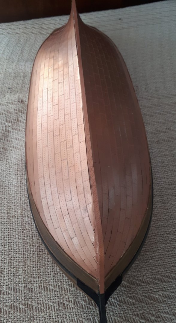
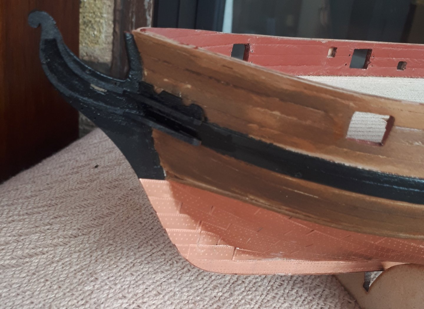
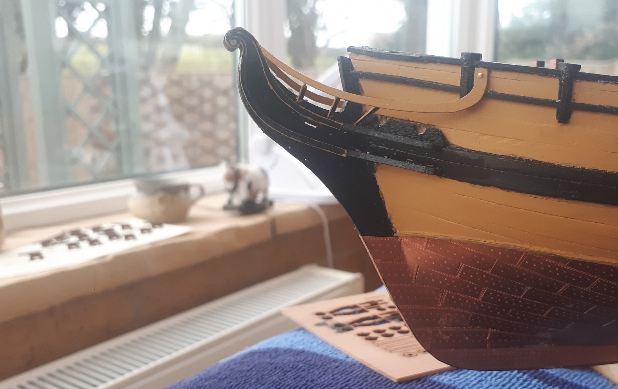
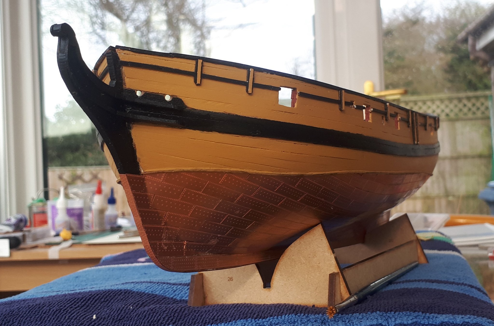
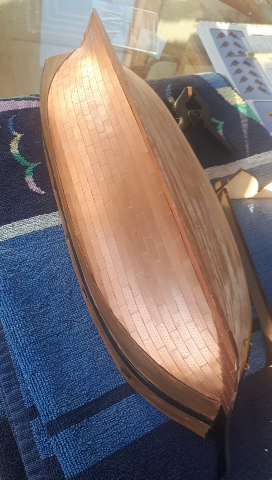
I have finally completed the copper plating task. I am reasonably happy with the end result. It took a while to find the best working method which was to add a drop of ca to the centre of the plate and then to position the leading edge against the previously fitted plate and once I was happy with the alignment I then gently dropped the plate , using a metal pointer to make any minor alignment adjustments before the ca glue cured.
Once the copper plating was completed I then added the hair brackets (which required a bit of trimming) , the bow checks and the hawse bolsters.
The next task will be to drill out the hawse holes with a 2mm drill and then to fit the capping rails and stern counter side timbers. This will not take took long to complete so I can also fit the upper rail and swivel gun post patterns.

- bruce d, KARAVOKIRIS, DelF and 3 others
-
6
-
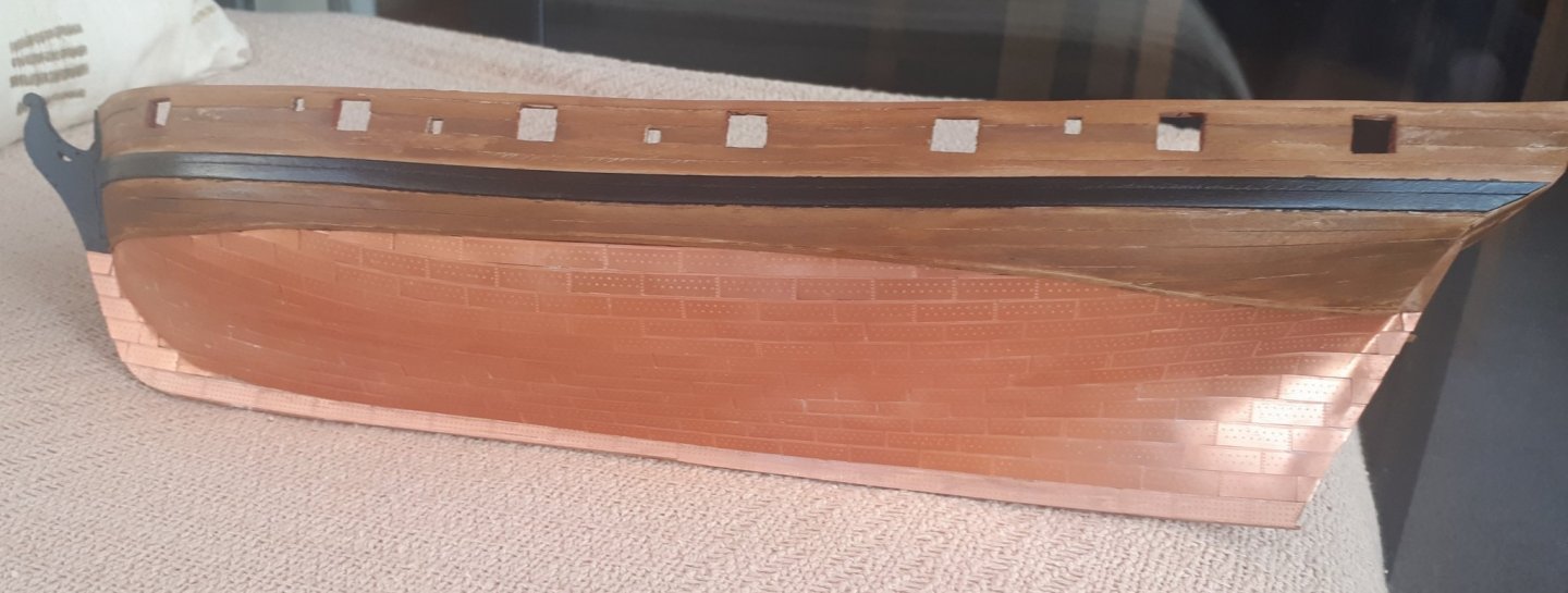
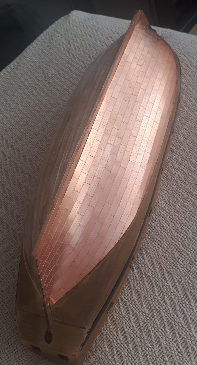
I have now completed the copper plating of the port side (take 2). I have much happier with the results this time. I started out using the evo-stick instant for this task which I had used when for HMS Victory, however I soon reverted to using CA glue.
I did add a 1mm x 1mm strip along the water line which really helped to get a neat finish.


- ccoyle, Edwardkenway, VTHokiEE and 7 others
-
10
-
1 hour ago, VTHokiEE said:
That’ll look really nice, I’m planning on rigging them for my Alert as well after seeing the beautiful job the Blue Ensign did on his. I’ll be looking forward to see how you rig yours (I’ve never done it before and am trying to learn as much as possible before I get there).
Take a look at the following for my attempt to rig cannons a few years ago.
- Rik Thistle and VTHokiEE
-
2
-
-
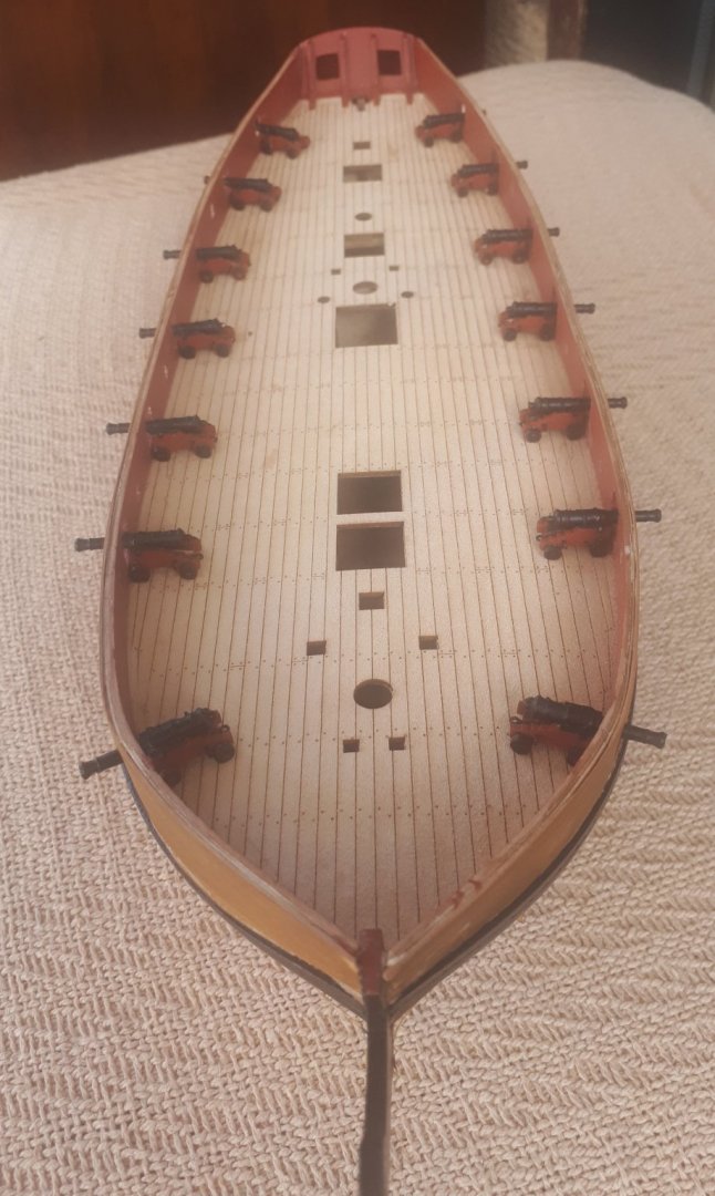
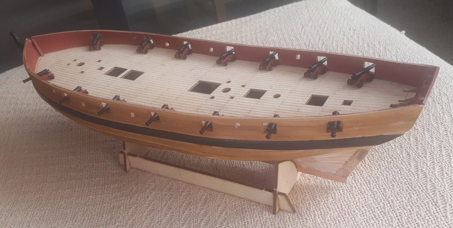
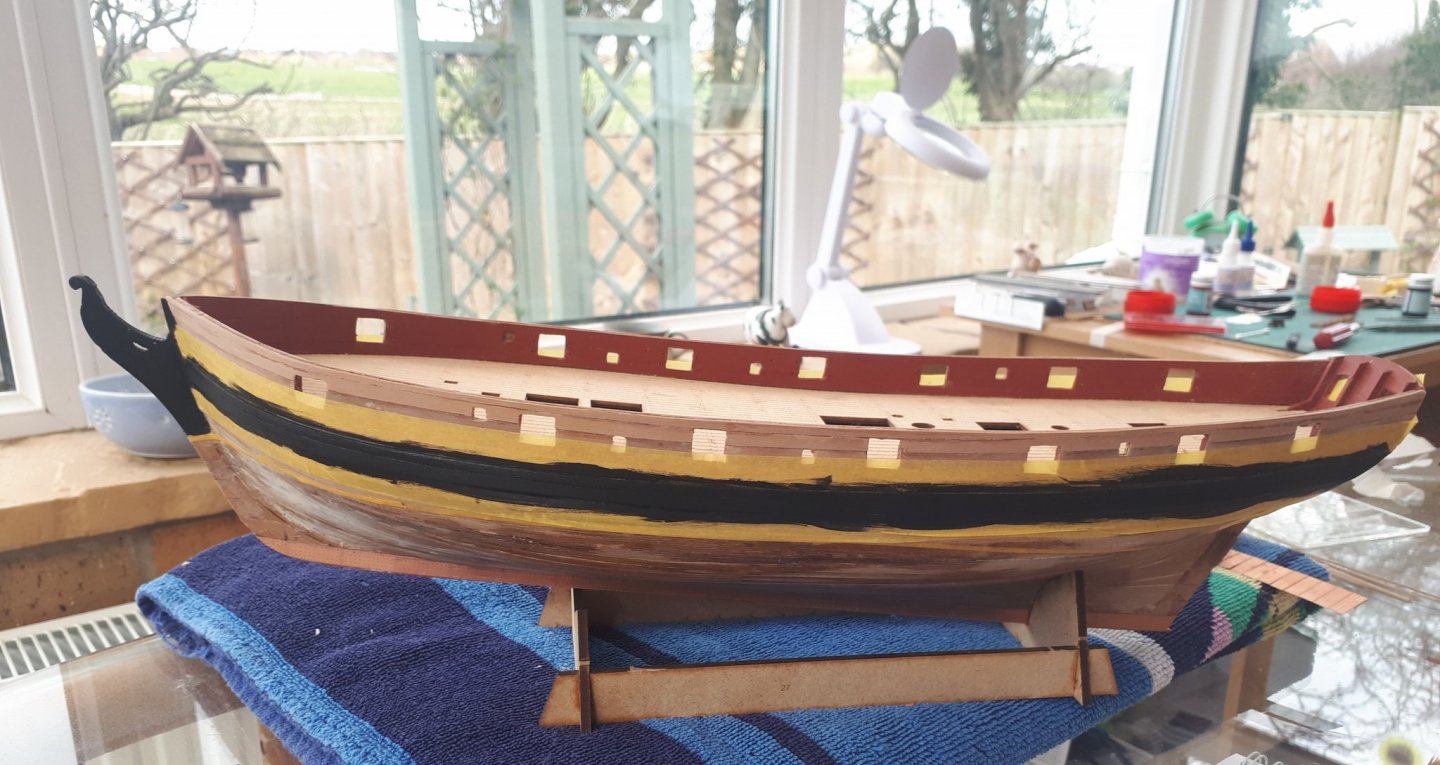
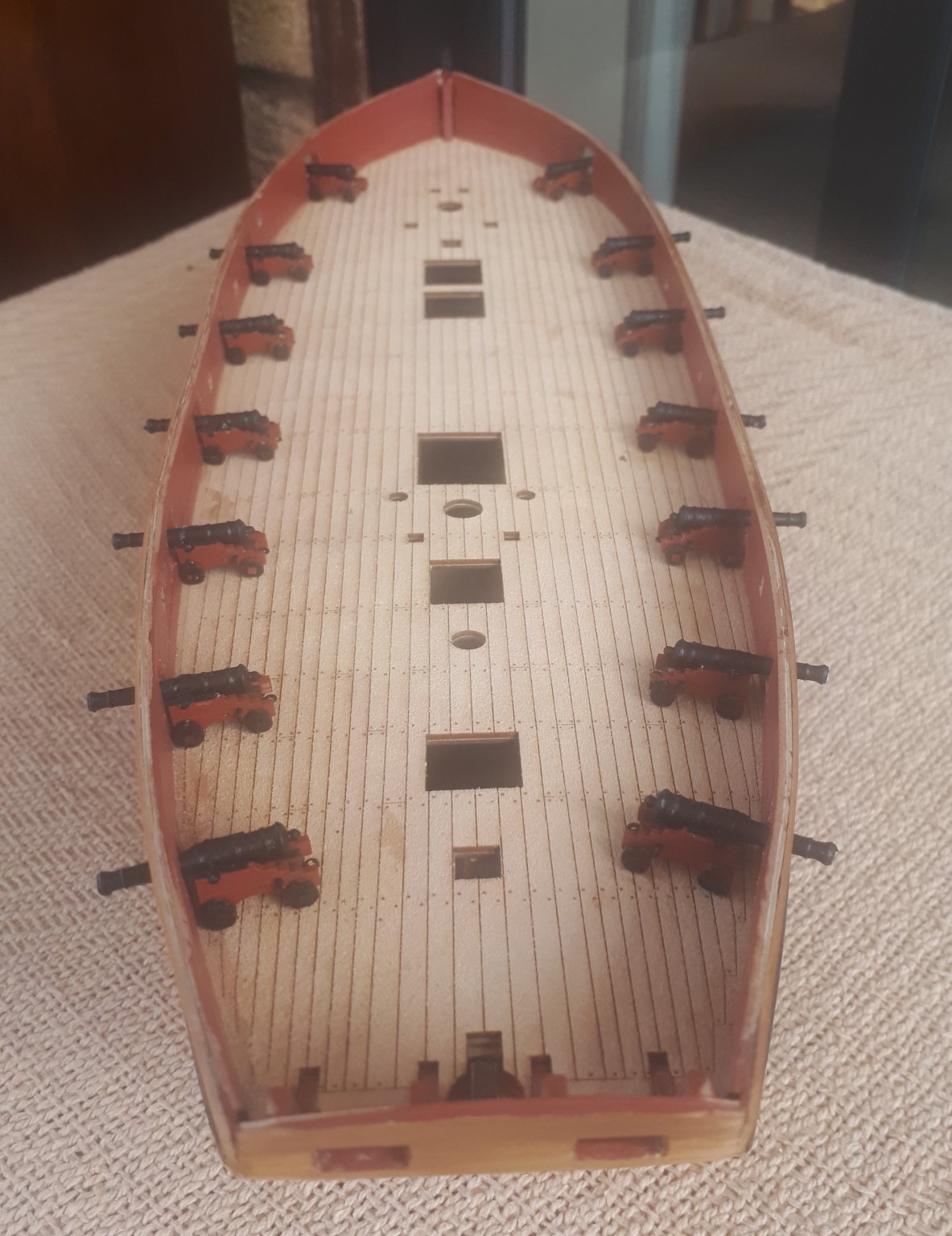
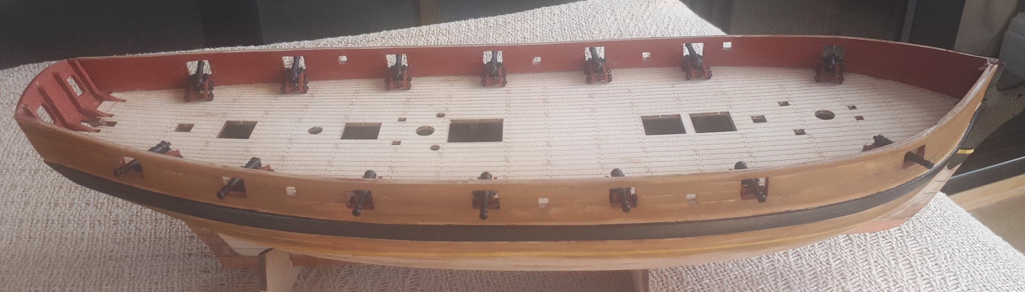
I went ahead and completed the assembly of all 14 off 4 pounder cannons. The Speedy is now armed and ready for action!!
I will redo the copper plating next.


-
The new copper plates I have ordered have now been shipped, so they should arrive by first class post sometime tomorrow.🤞
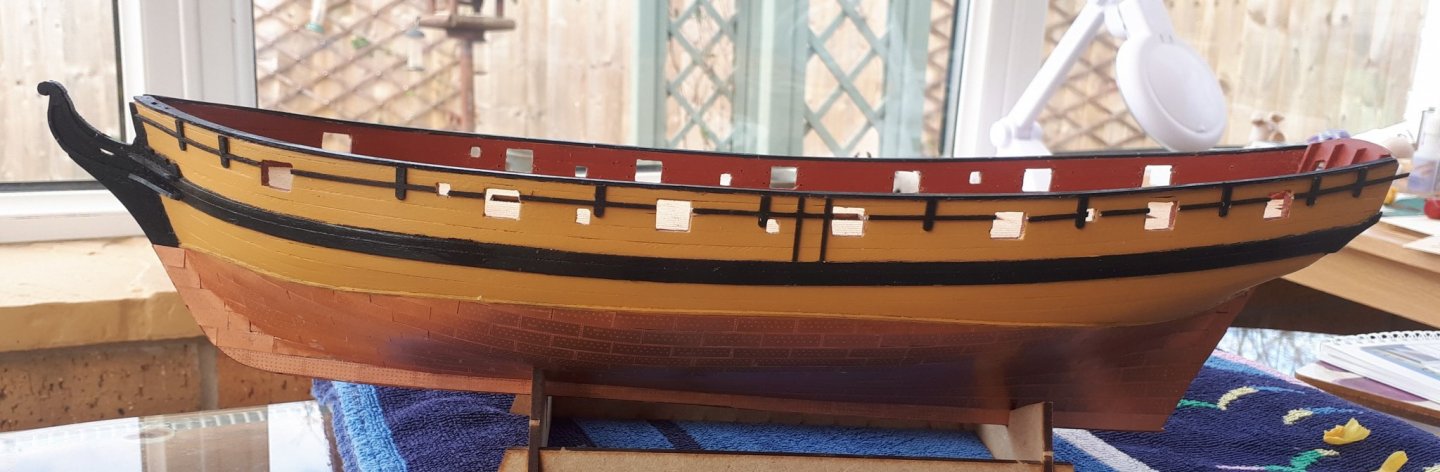
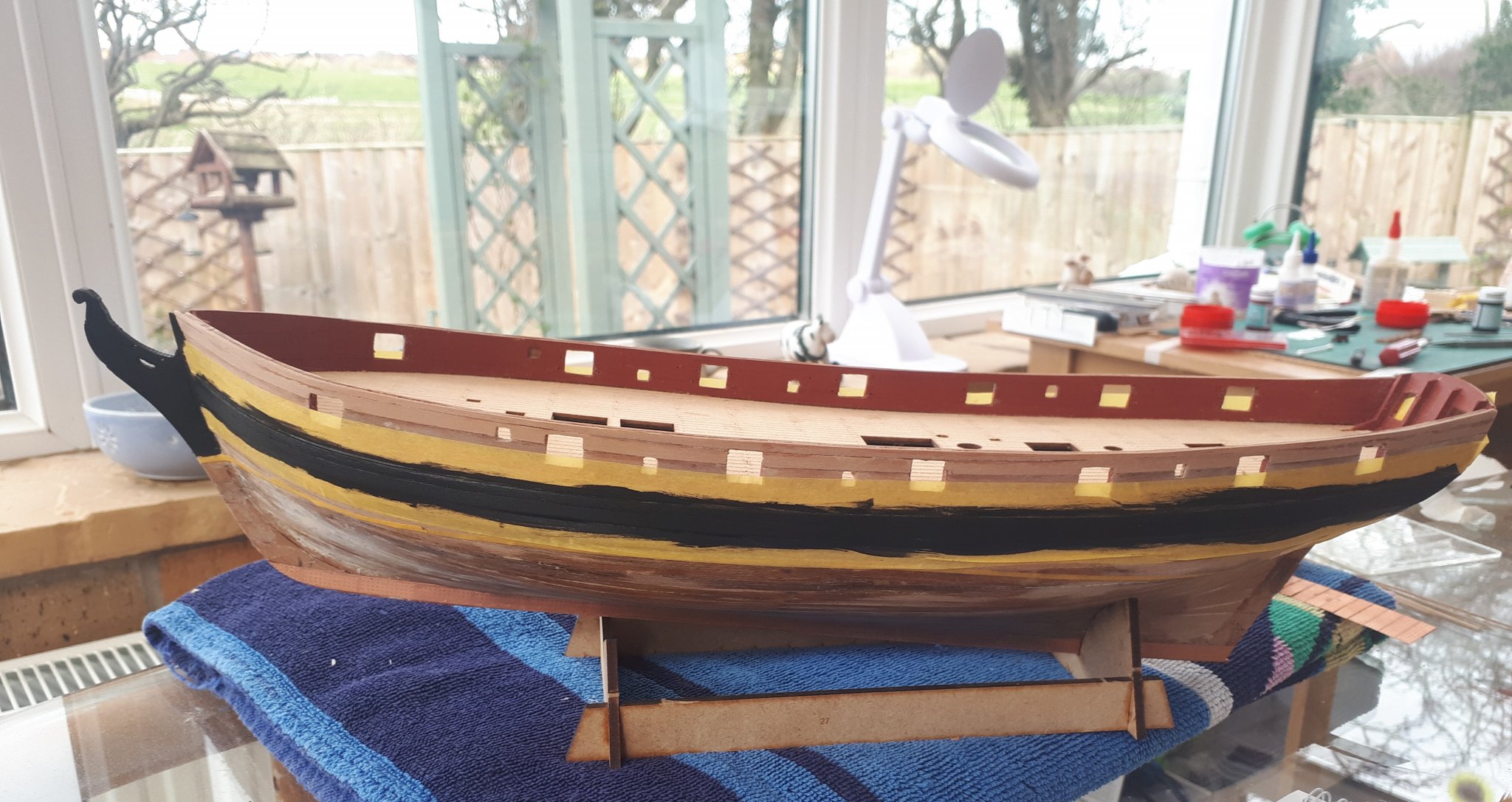
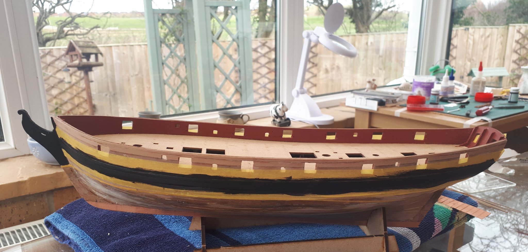
In the meantime I decided to paint the Wales.
I have applied 3 coats so far, giving the Wales a light sand between each coat. I will give it the wales a final coat later on today.
In the attached pictures below you can see my work station (and working outlook) in the top right corner of the two photos.
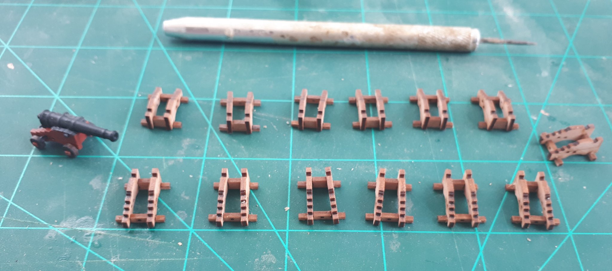
In between the coats of paint I continued with the assembly the 13 outstanding 4 pounder cannons. The gun carriages are now ready for painting with the fully completed cannon looking on, like an expected parent.


- egkb, GrandpaPhil, VTHokiEE and 5 others
-
8
-
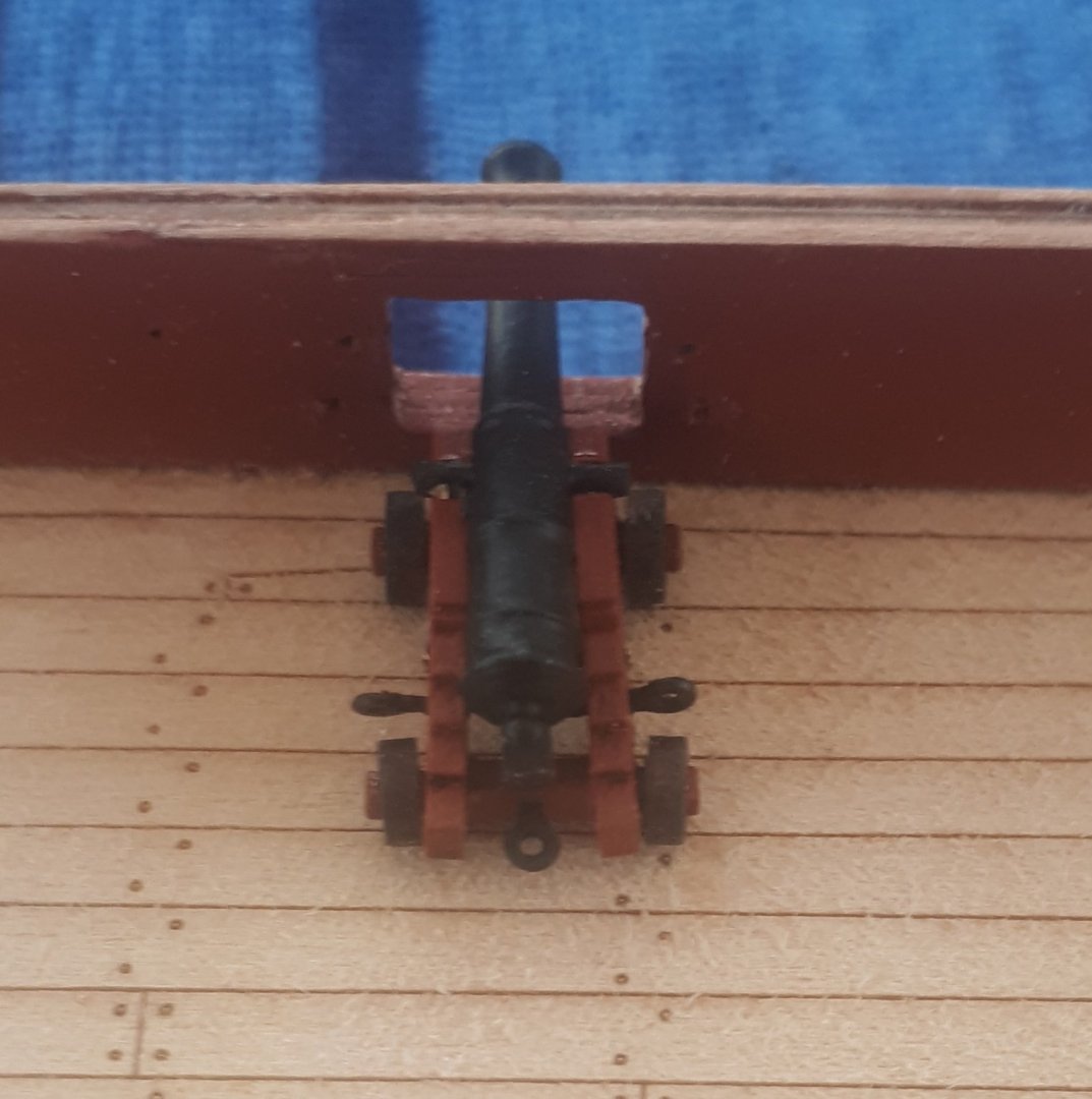
While waiting for the new copper plates to arrive I decided to build one of the 14 off 4 pounder cannons.
I started with the standard dry fit.
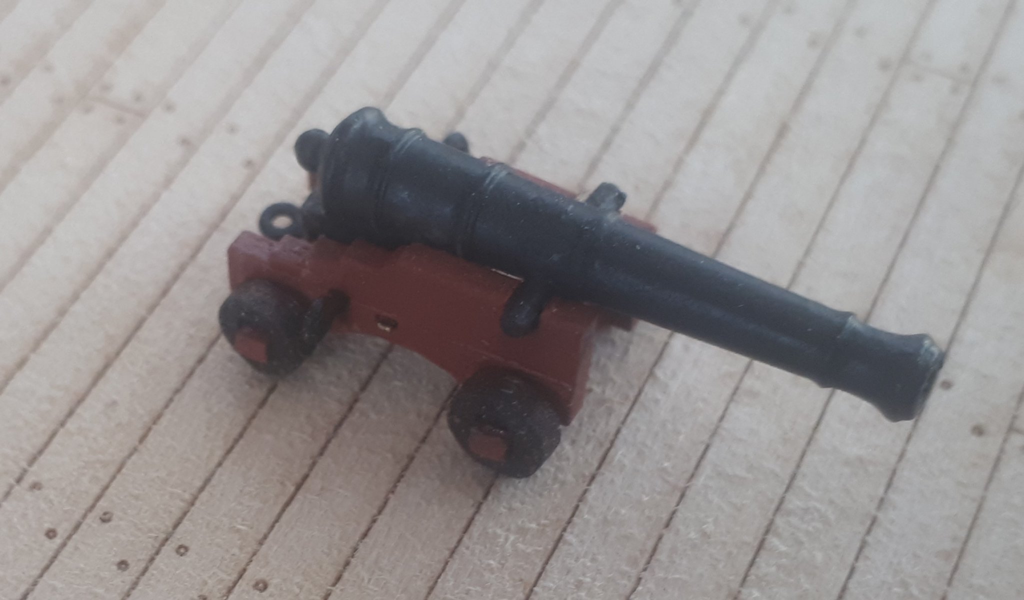
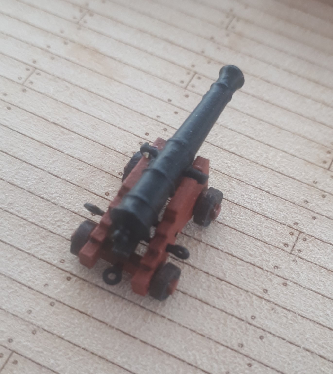
As everything was a good fit I went ahead and painted all the photo etched brass parts using my gun metal black paint along with one of the cannons. I applied a few light coats of paint and then built the first cannon.
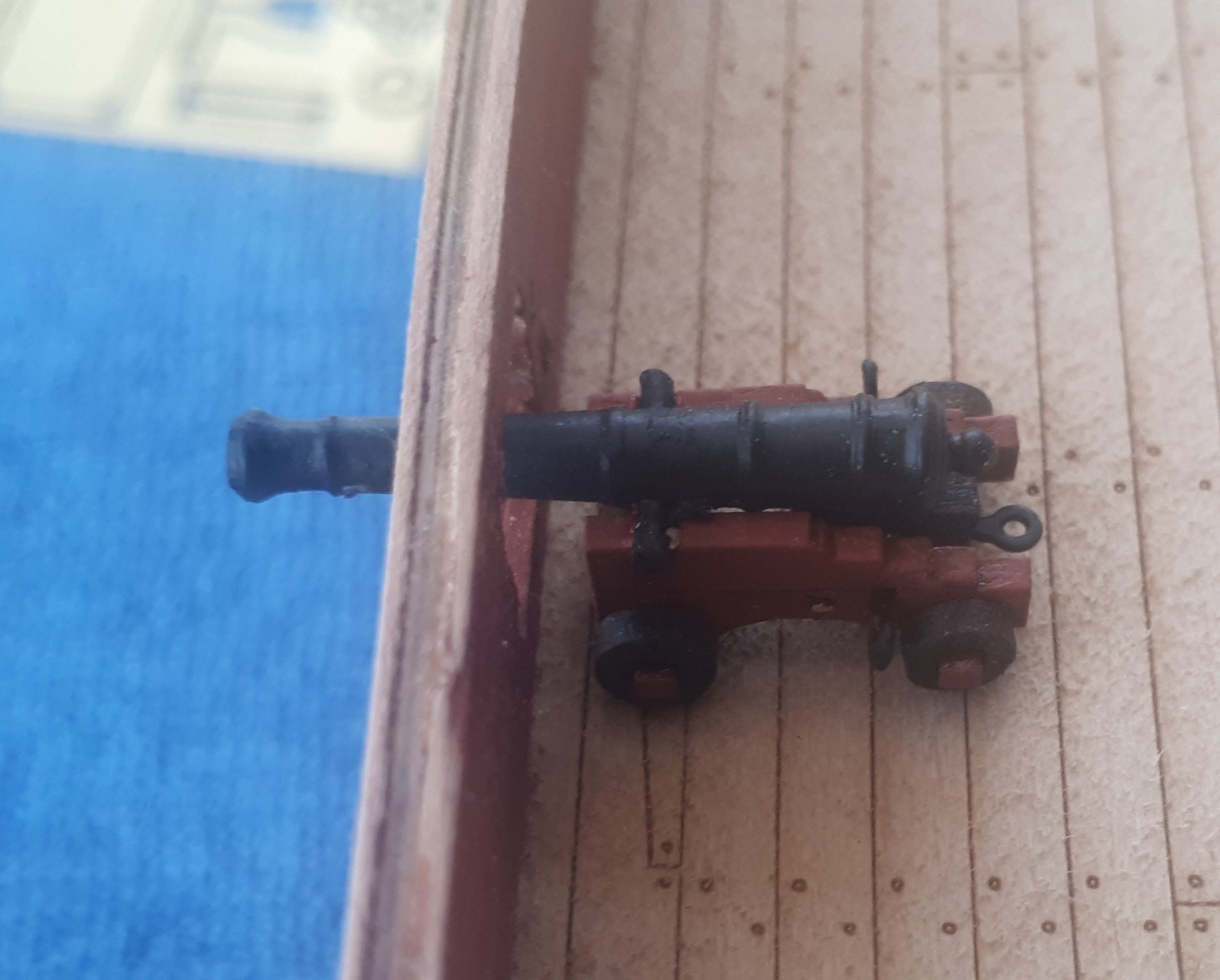
I was very happy with the end result and it looks really nice when positioned at a gun port, sitting nicely in the centre of the gun port opening.


- DelF, VTHokiEE, chris watton and 4 others
-
7
-
9 minutes ago, DelF said:
Looking good. I've not seen the masking tape idea before - I found the youtube channel you mention but there's loads of videos. Any idea which one covers tape? As an alternative, I find shrink wrap tube useful for these sorts of jobs - cut a slice off an appropriately sized tube apply a heat gun and you're done. I got about 100 year's worth of black tube from Amazon for peanuts.
Derek
Hello Derek
Go to the link below (Part 47 of HMS Victory: Mizzen Lower Mast) and it starts at 10 min 30 seconds into the video.
-
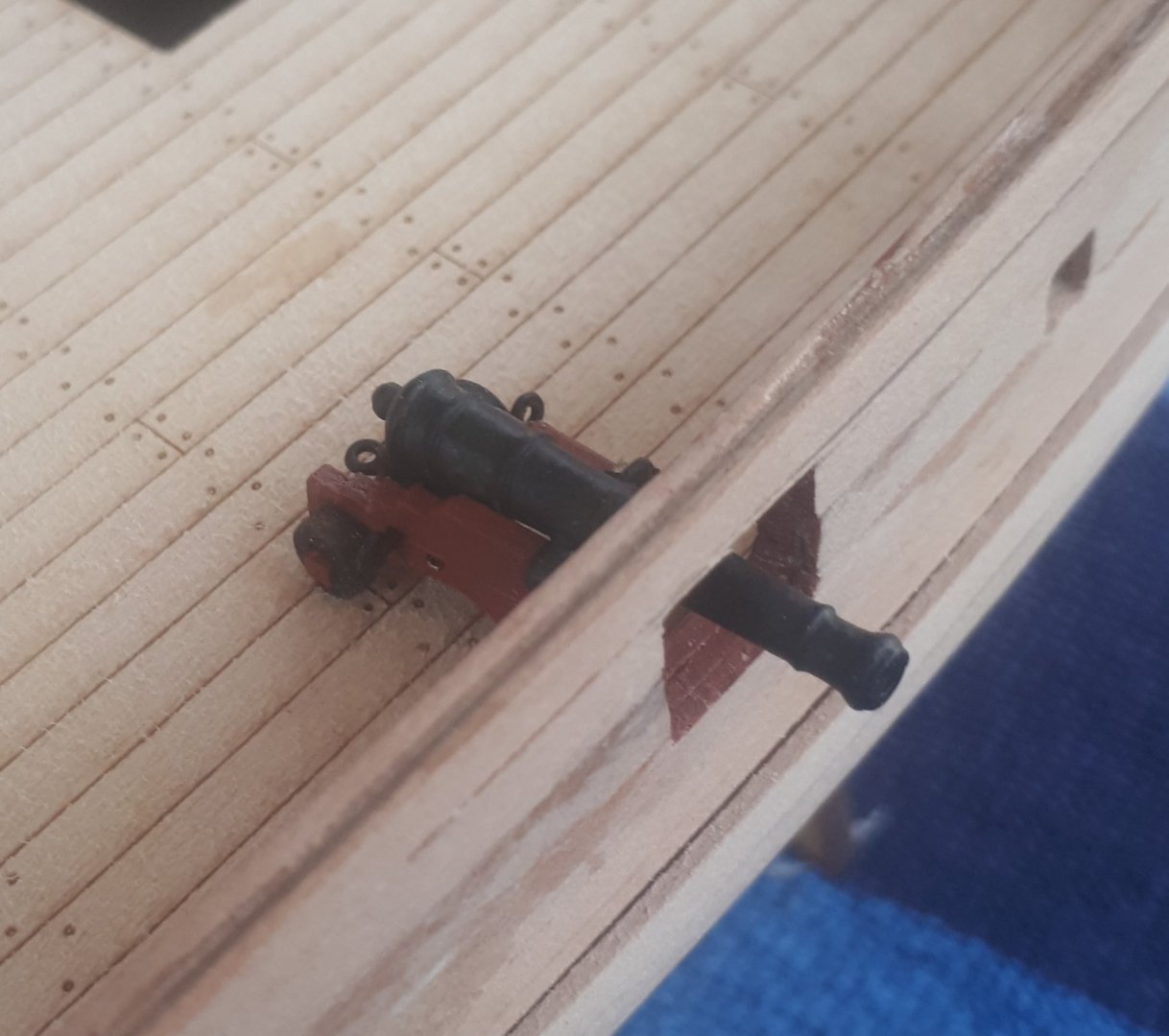
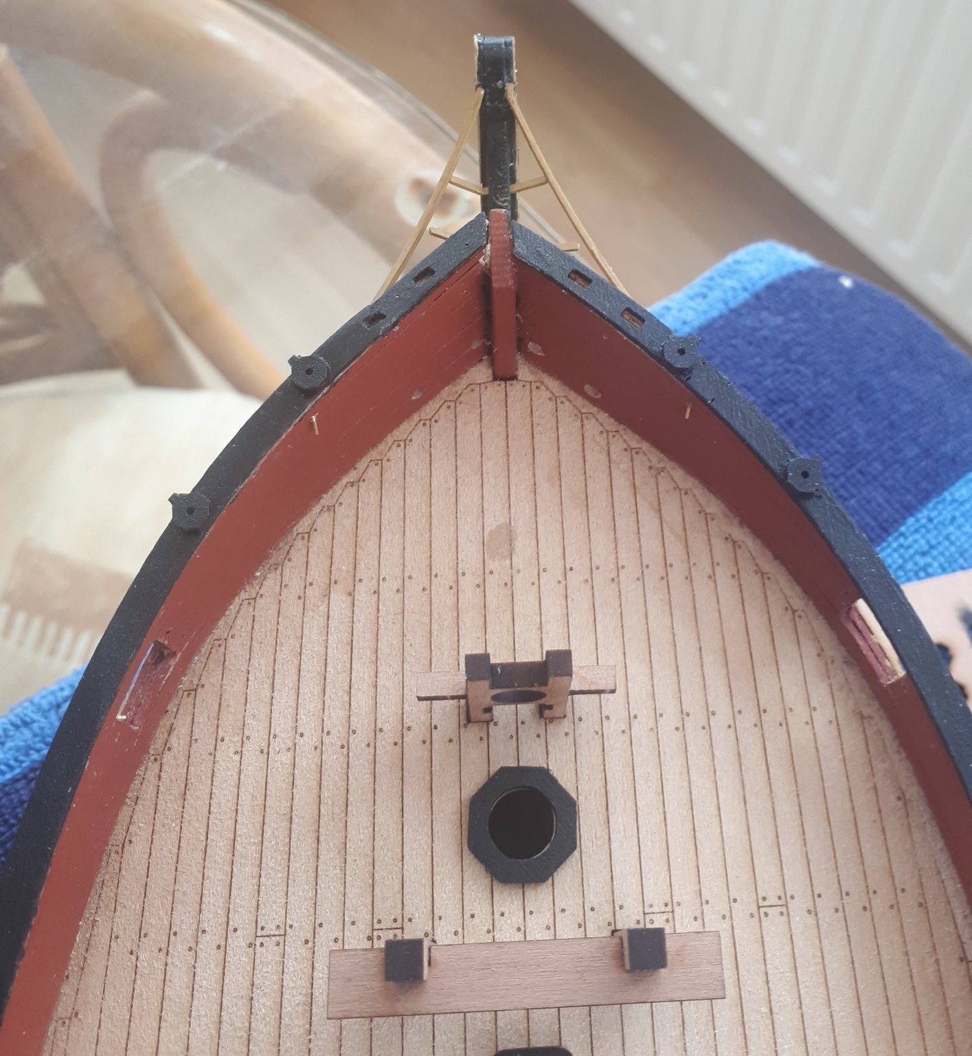
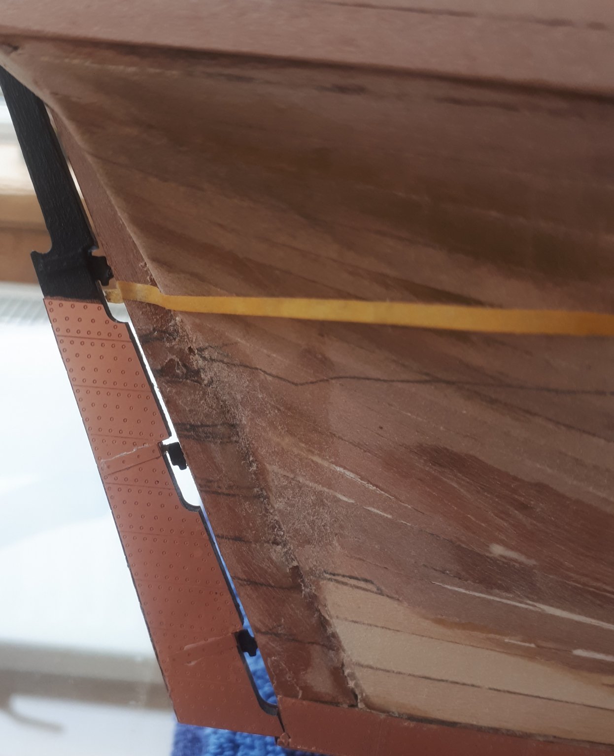
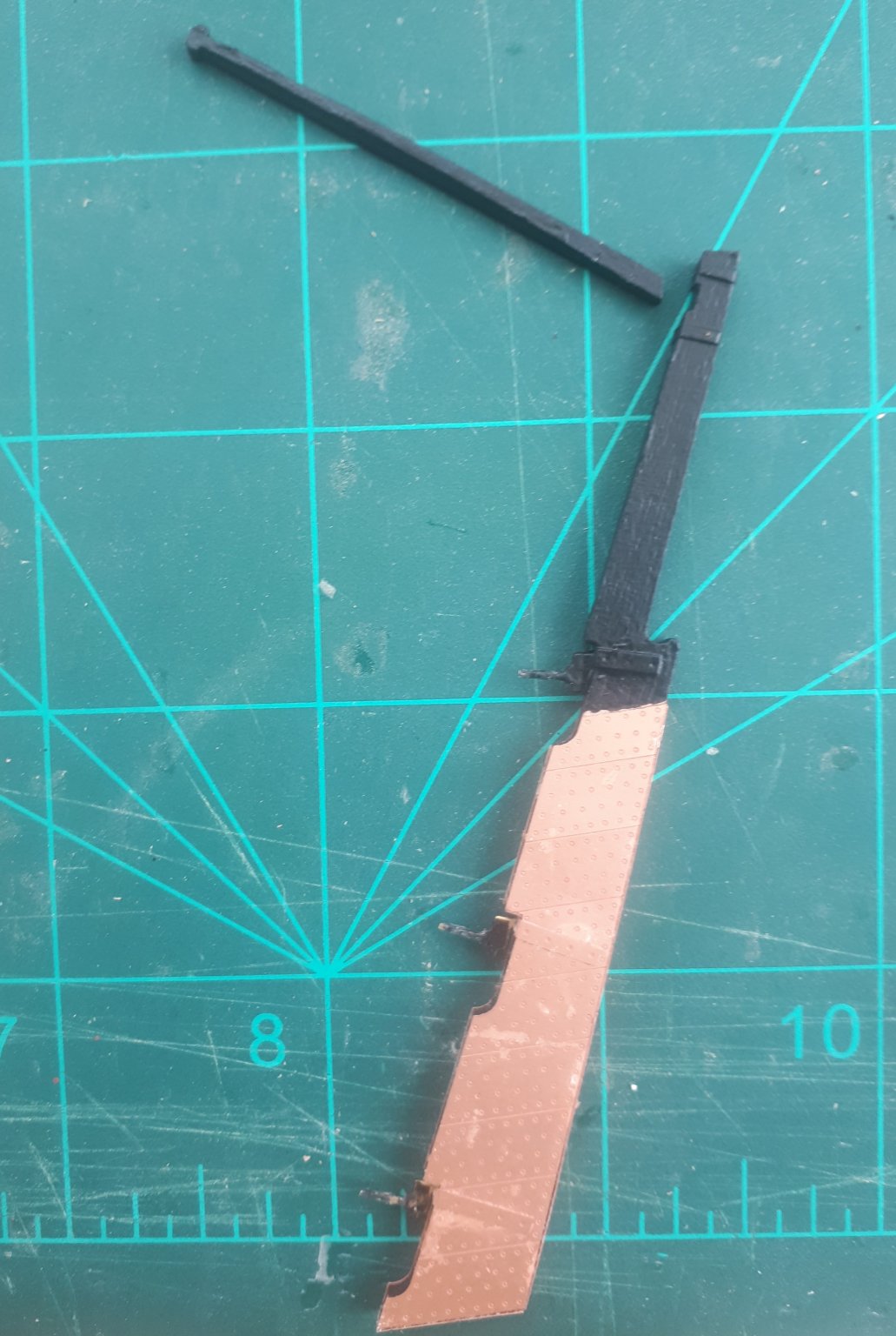
Today I did a test fit of the completed Rudder assembly. With a bit of experimentation with the fitting I found the pintle braces worked best for me with the top one located in the rudder and the lower two fitted to the stern post.

The tiller arm has also been assembled and painted but will not be fitted until after the rudder is finally installed.
I used masking tape (see "John Builds Iconic Military Models YouTube channel) to add the two banding strips to the top of the rudder as can be seen in the photo below, this worked really well.

- egkb, GrandpaPhil, glbarlow and 4 others
-
7
-
-
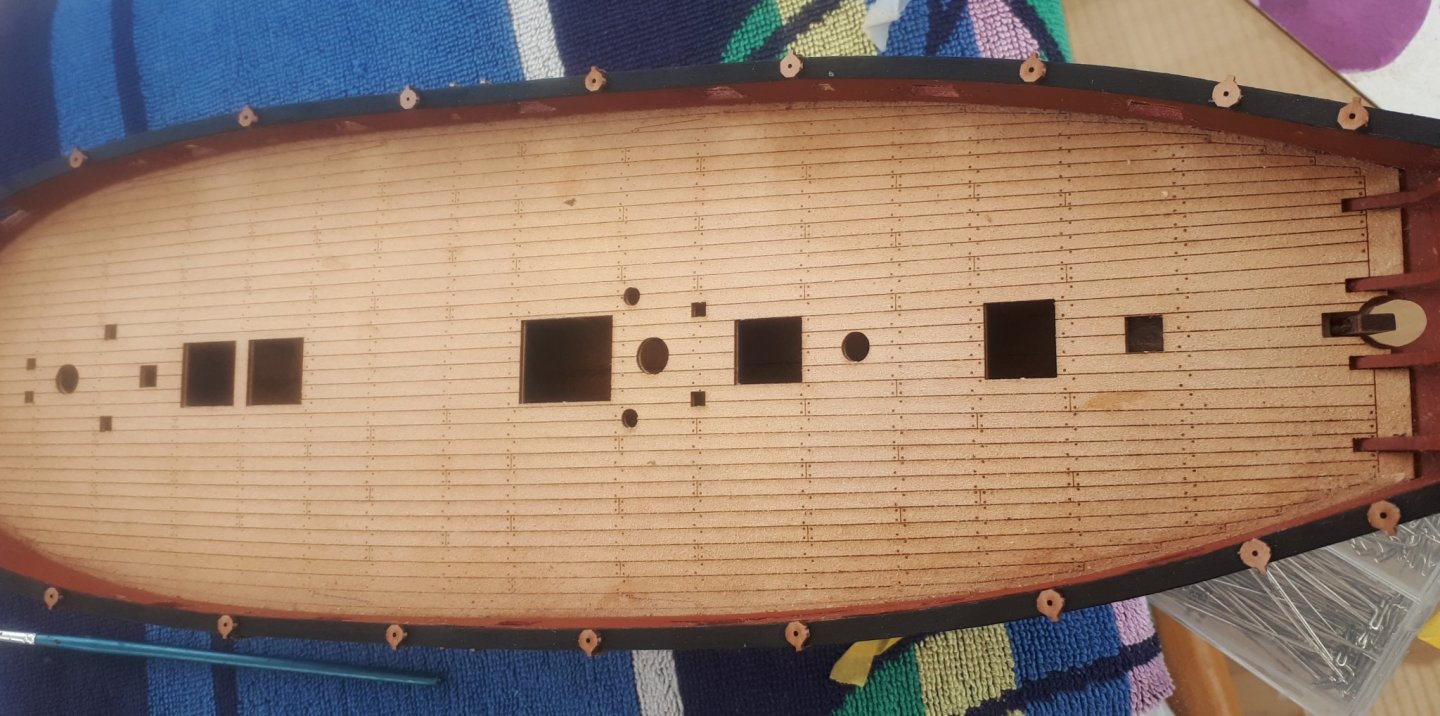
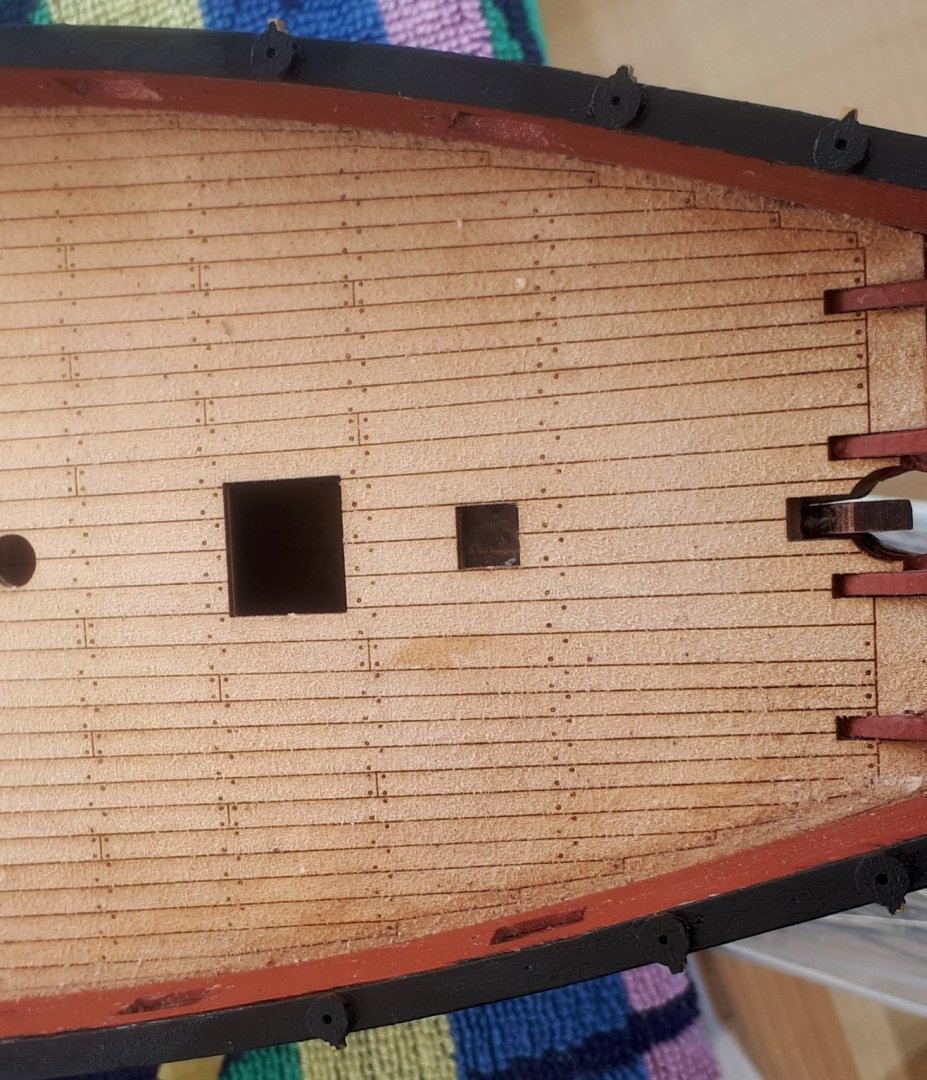
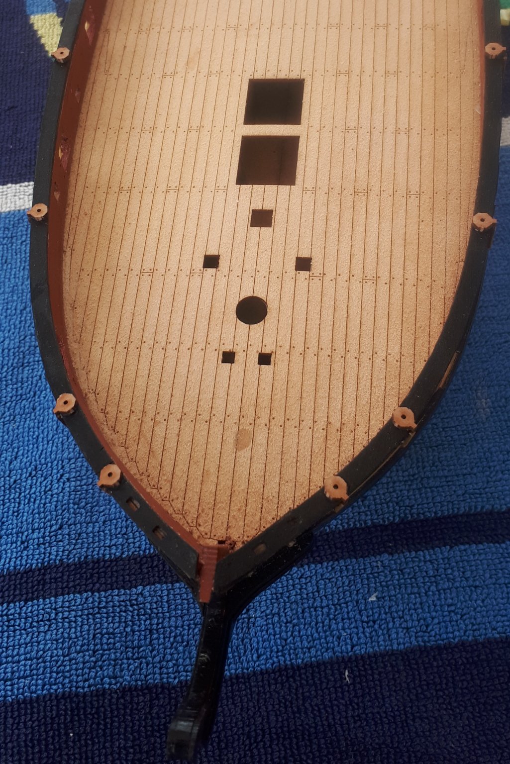
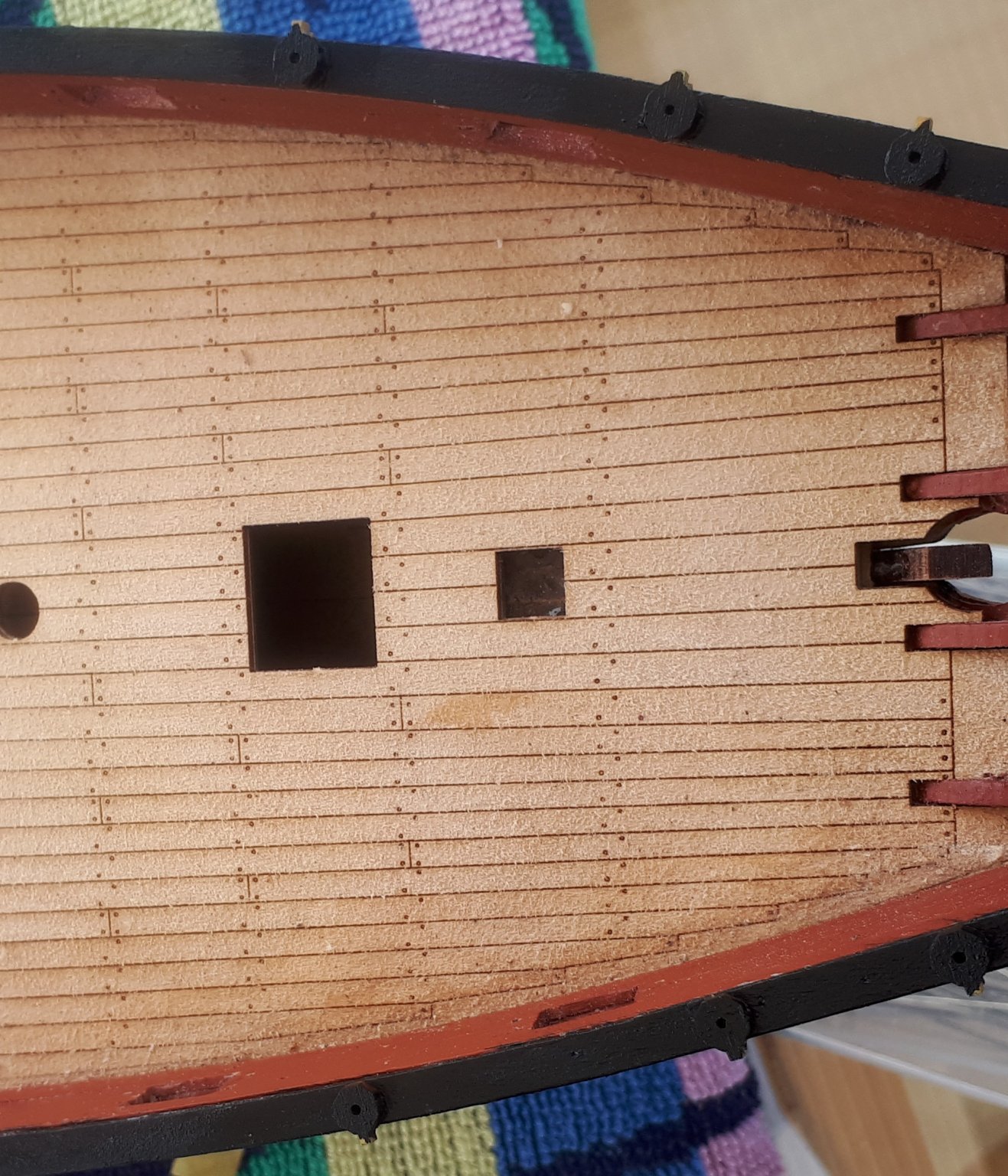
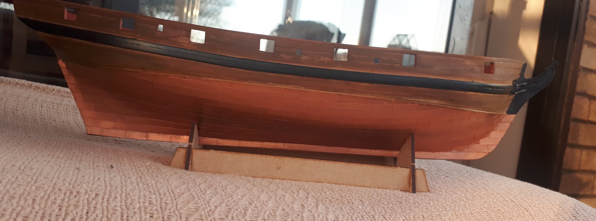
After removing the copper plates yesterday I took time to study the build photos in the manual and information on plan sheet 4.
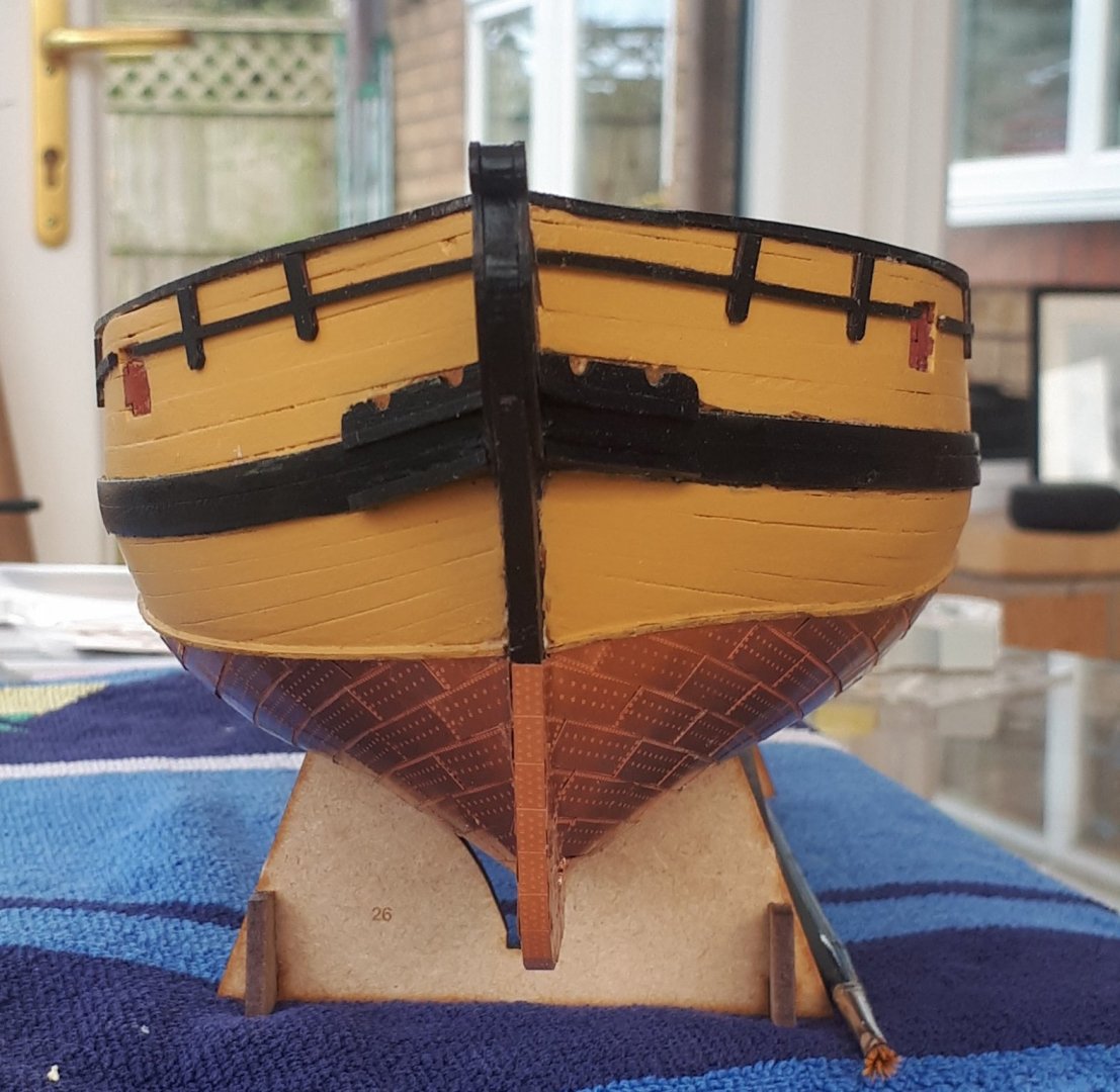
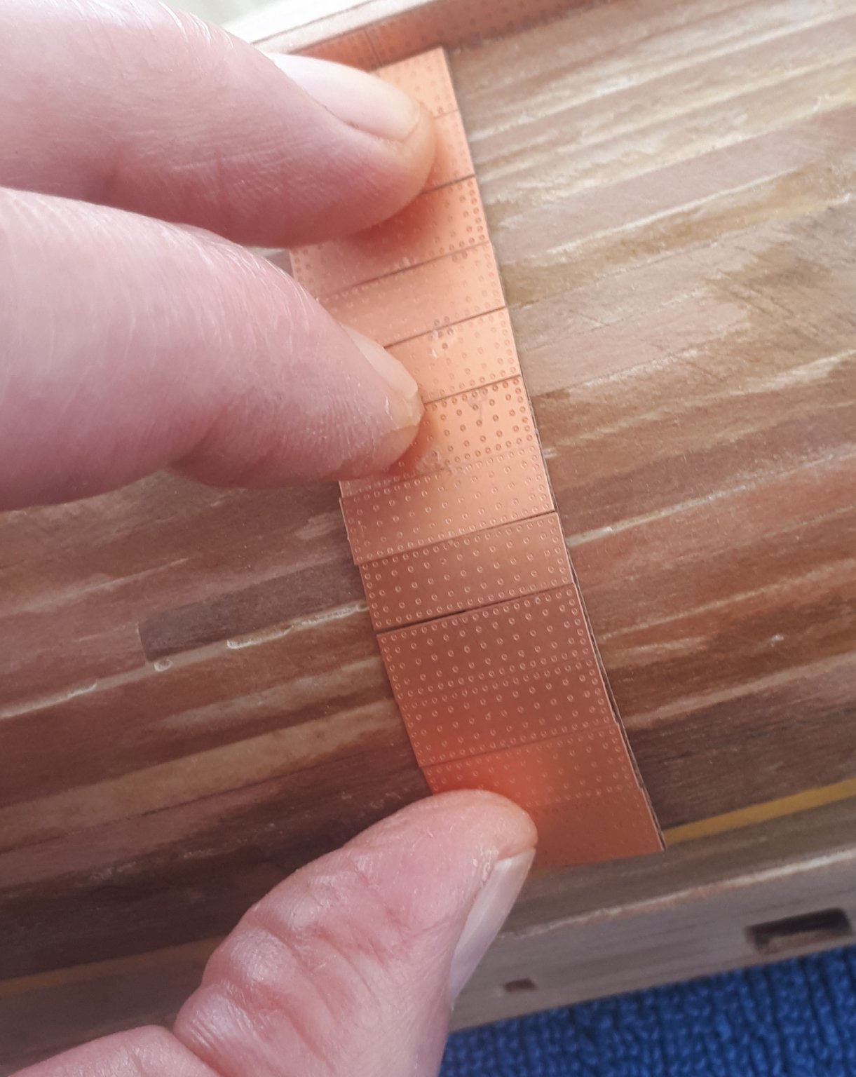
At the widest point it will require 12 rows of copper plates, ignoring the small slithers on top of the 12th row. At the bow end there are 5 rows of copper plates and at the stern there are 8 rows of copper plates.
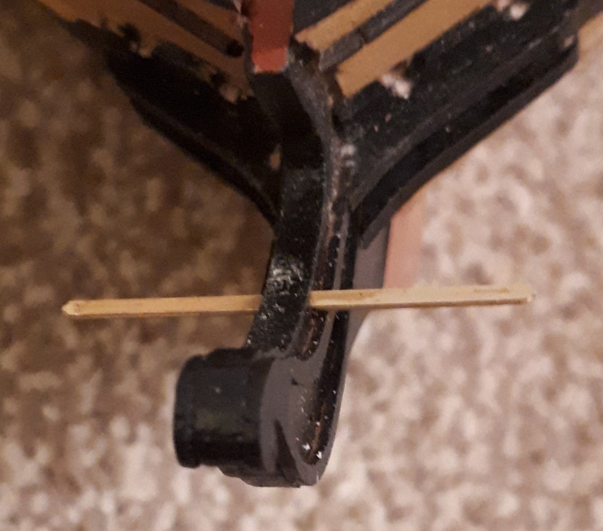
I decided to make a small jig comprising 12 copper plates on a flexible Vernier backing to mark the position of the water line at the widest point, as shown in the photo below.
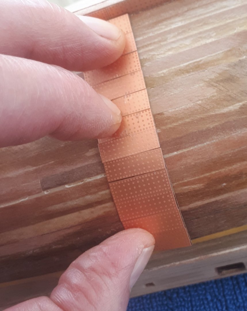
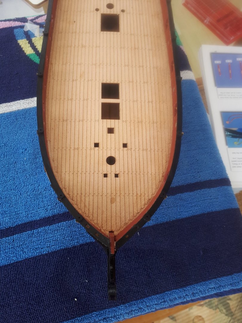
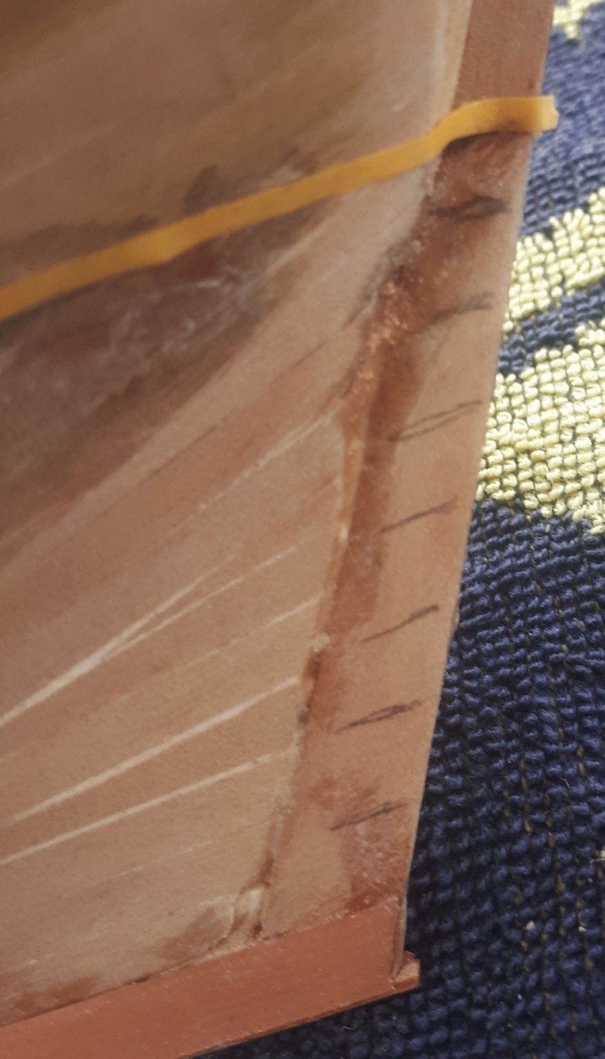
Noting there were 5 rows copper plates at the bow, I marked them off. The incorrect water line position from my first coppering is still visible in the photo below. coming in after 4 rows of copper plates.
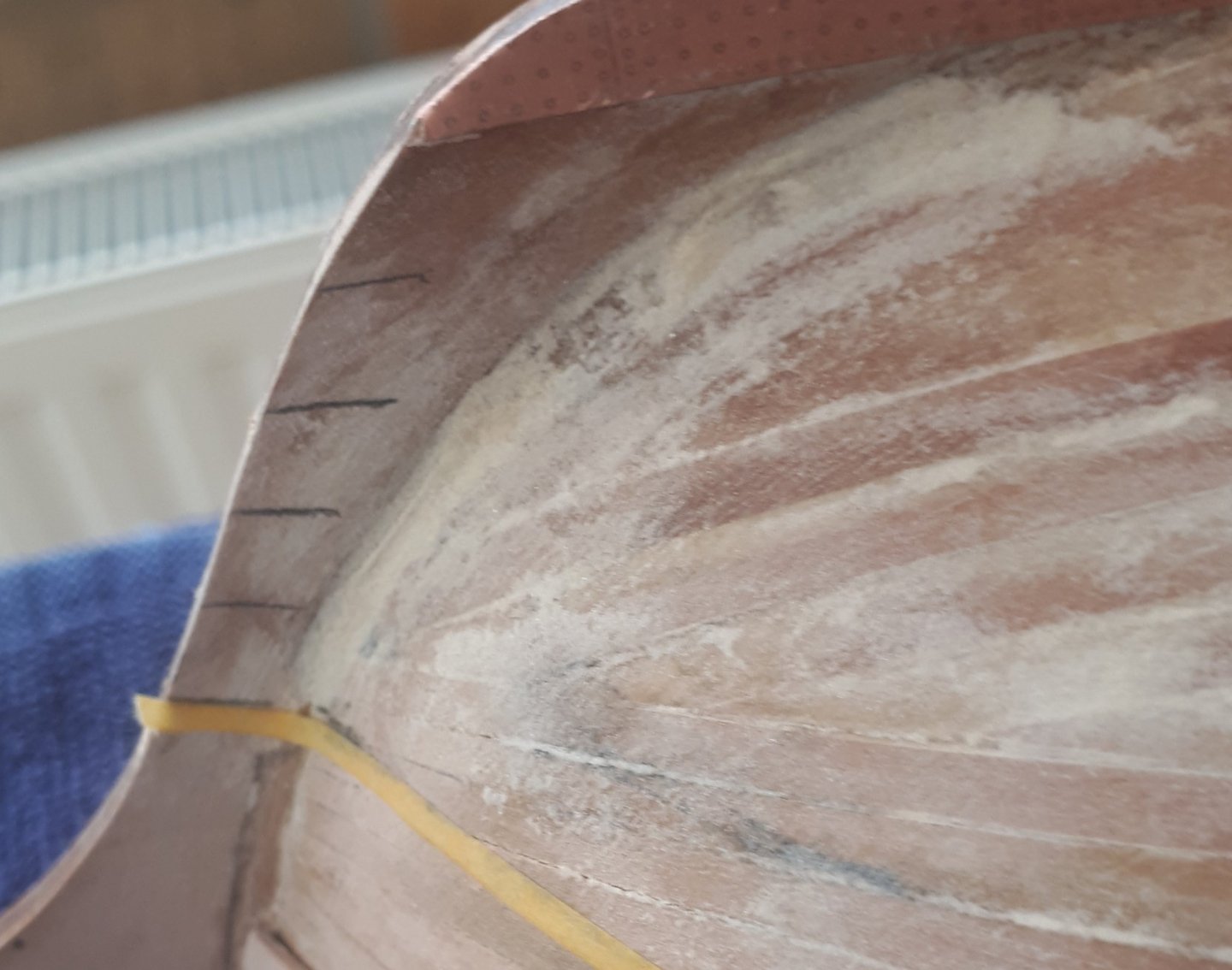
Using the copper plated rudder part as a guide I then marked off the 8 rows of copper plates at the stern. Again the incorrect water line is still visible on the photo below, coming in after 7 rows of copper plates.
 .
.
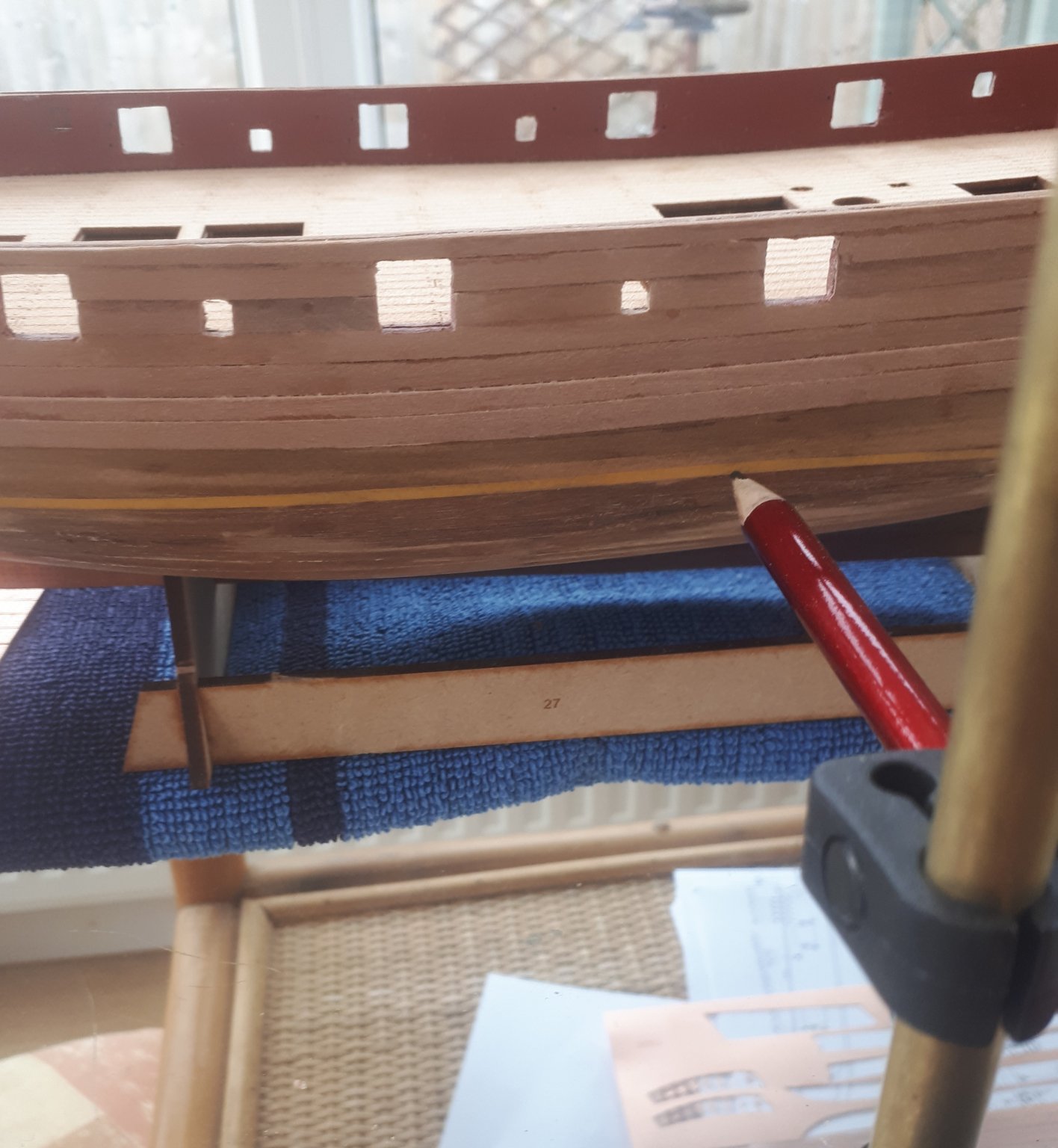
Using a 1mm by 1mm strip of wood taped to the hull I was then able to indicate the correct position for the waterline. I verified the position at different points along the hull using the photos in the manual as a point of reference. I was then able to draw the waterline using the 1mm x 1mm strip as the guide. I then removed the wood strip and used some 2mm masking tape to highlight the position of the waterline. As a final check I used my water line marking tool to double check the water line position indicated by the tape. I am now very happy the water line is correctly marked. I will redo the copper plating early next week when I get the replacement copper plates from Cornwall Model Boats (probably on Tuesday). As the copper plating progresses I will glue a strip of 1mm x 1mm along the water line so that I get a really neat looking finish to top of the copper plating.

-
2 hours ago, VTHokiEE said:
What did you do/use to take off the plates?
I just used my craft knife to pick at a corner of a copper plate and once I had lifted an edge it was easy to pull the plate away. They all came off without too much effort and it took about 60 mins in total to remove approx. 460 copper plates.
I could tell the difference between the plates I had secured using thin ca glue and medium ca glue.
I have now sanded the hull to remove the residual ca glue and I will be good to go again once the new copper plates have arrived.
-
I have not been totally happy with some of my copper plating. As I progressed with this this task I did find the best method that worked to get the plates to fit neatly.
I did rip off some copper plates that could have been fitted better and replaced them. However when I checked the copper plating on the rudder with the copper plating on the hull I noticed my water line was too low, by 1 row of tiles.
It would be possible to leave the existing copper plates and add the additional plates but I have now decided to rip off all the copper plates fitted and start again. I have ordered some new 1:64 scale copper plates from Cornwall Model Boats (which were the same size as the kit supplied plates, i.e. 19 x 6mm)
I might revert to using the evo stick impact glue as well and I will add the 1mm x 1 mm strip along the water line before I start the copper plating.
Based on the time taken so far I would expect it will take approx. 2 day per hull side to plate the hull.
-
16 minutes ago, glbarlow said:
I think maybe he meant this Glenn😬
I was referring to my Speedy build, sorry for any confusion.
-
-
1 hour ago, DelF said:
I like the idea of a strip along the edge of the copper. Another idea I’ll borrow!
Derek
It worked really well on my Victory build, a 1mm by 1mm strip is very bendy and not very visual.


.jpg.5f351f8f1d7900667015f7a99b88bb37.jpg)
.jpg.99cb75ca06af0d7206a7a9e1c37e914f.jpg)


HMS Speedy by Delf - FINISHED - Vanguard Models - Scale 1:64 - Master Shipwright edition
in - Kit build logs for subjects built from 1751 - 1800
Posted
Looks really good, slow and steady is the best way.