HOLIDAY DONATION DRIVE - SUPPORT MSW - DO YOUR PART TO KEEP THIS GREAT FORUM GOING! (Only 53 donations so far out of 49,000 members - C'mon guys!)
×


ianmajor
-
Posts
784 -
Joined
-
Last visited
Content Type
Profiles
Forums
Gallery
Events
Everything posted by ianmajor
-
 Mike, Thanks. I have to go in to Manchester Central Library to revisit Lavery. I am happy to do that because I enjoy being surrounded by all those lovely books. Dafi's is another good example of the sweep immediately below a deck. I will keep looking for an above deck version. I suspect I will add a sweep - for interest's sake if nothing else! I read somewhere (on NMM possibly - can't remember where exactly) of a design of tiller that was semi hinged vertically but rigid horizontally to give flexibility over the curved deck whilst giving positive horizontal control of the rudder. I think it came under a "Captain X's patent design for...." type document. If such a joint was used I guess a sweep would be needed to stop the tiller sagging and scraping on the deck.
 -
Good heavens Dafi. You are worse than I am for attacking your ship with shovels and rakes and implements of destruction!
-
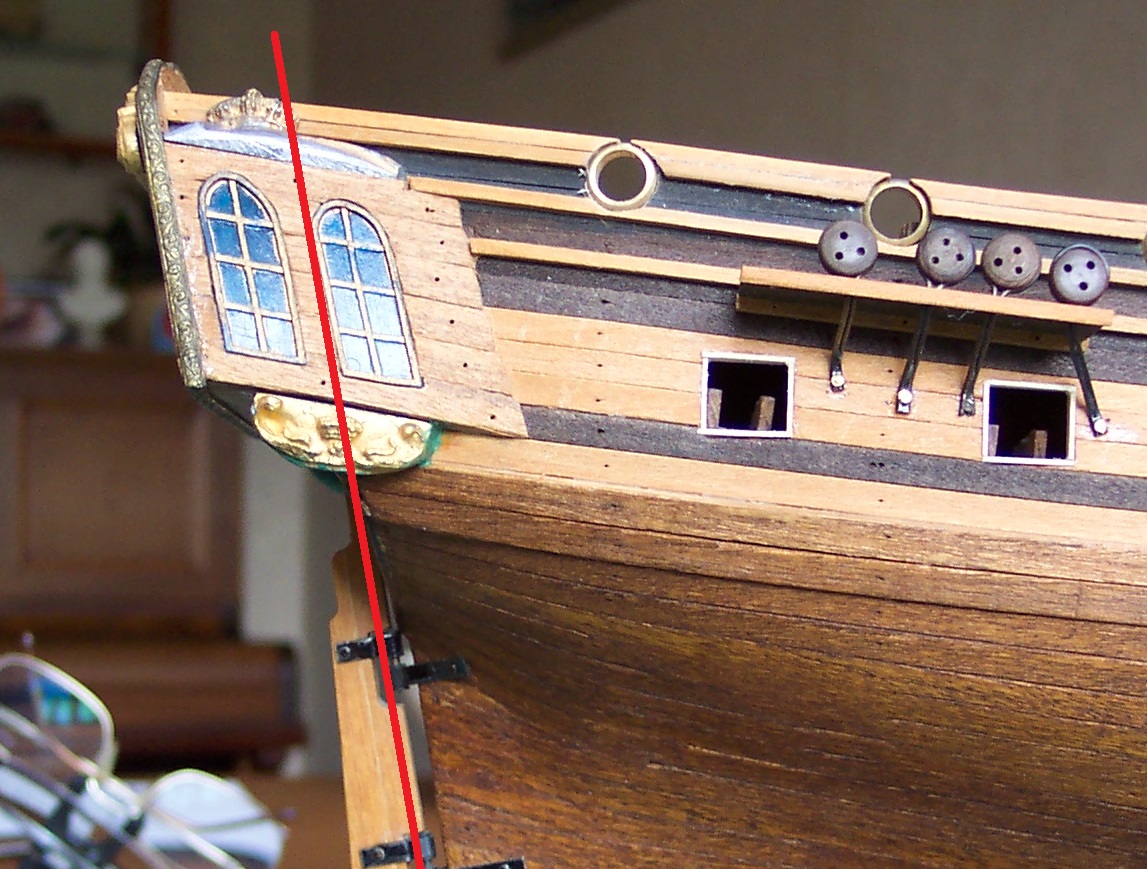
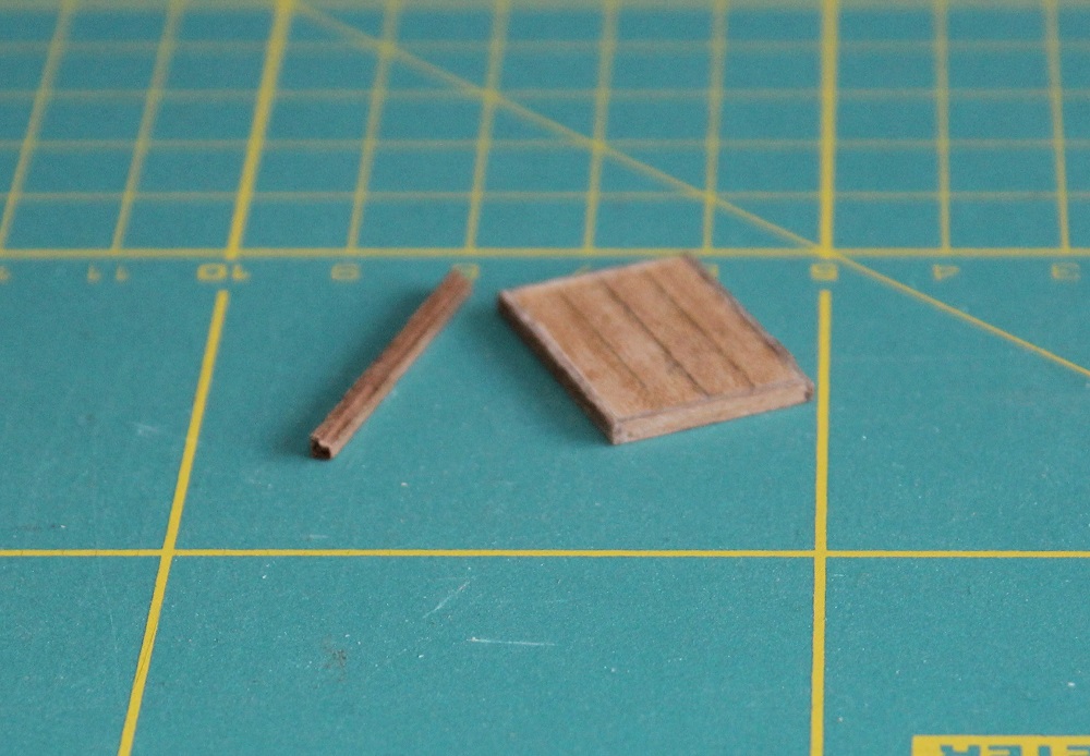
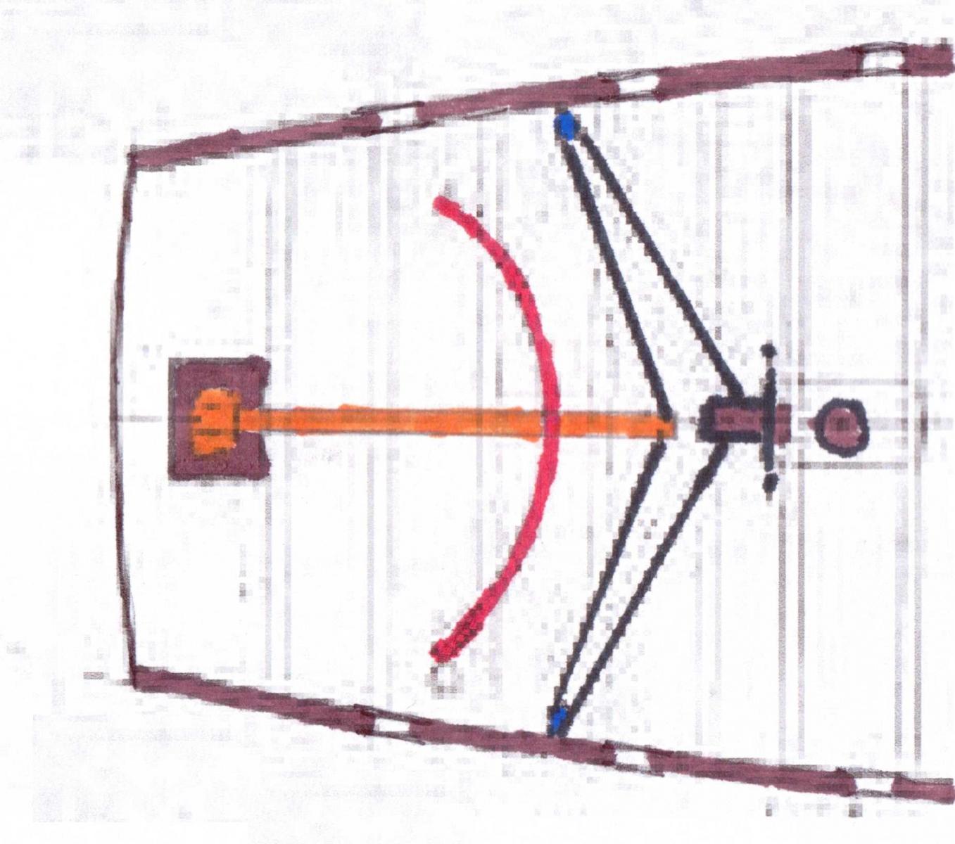
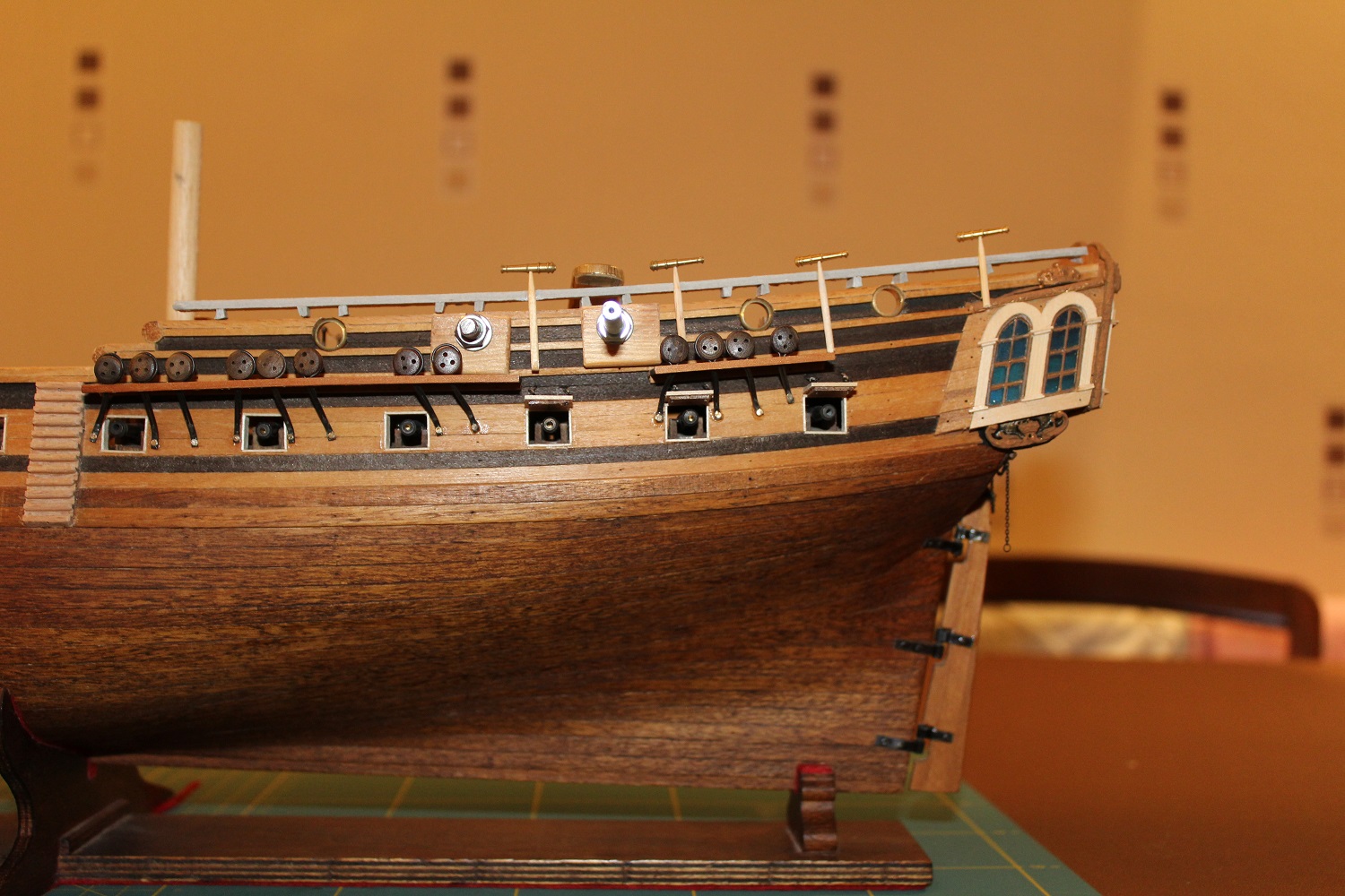
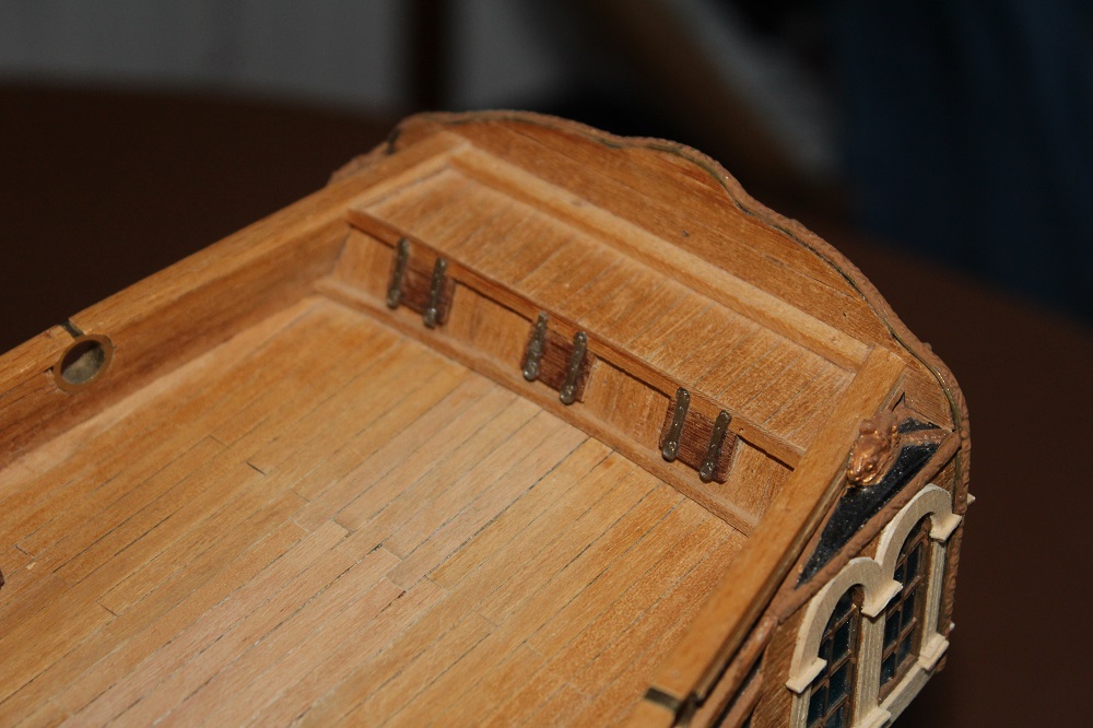
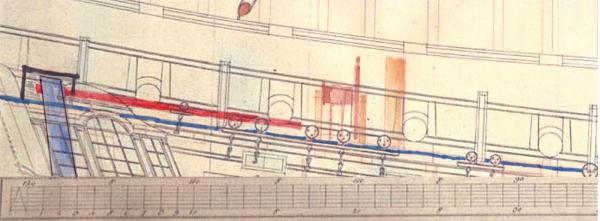
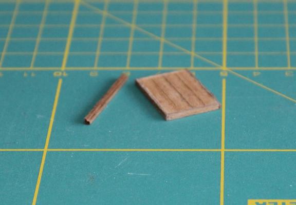
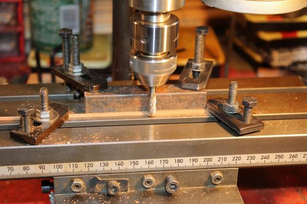
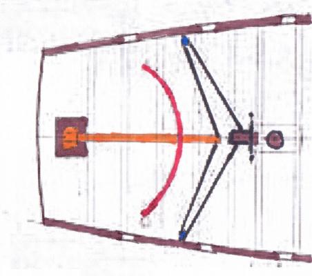
I started on the tiller in parallel with preparing for the work on the bulwarks. The Lyme plans show the tiller clearly above the quarter deck. It measures 15ft long and is 9 inches square at the rudder head tapering to 6 inches square at the wheel end. It is mounted with its centre line parallel to the quarter deck and about 9 inches above it. The cover on the plans is a plain rectangular box 2ft high, 4ft wide athwartships and 3ft long fore and aft. The following is a colour coded extract from the Lyme side elevation. I have picked out the level of the quarter deck in dark blue, the tiller in red, the rudder light blue, the wheel and mizzen mast in light brown. I will also be using this when replacing the rail and adding the swivel gun supports. To determine where the head of the rudder would be on the Unicorn I drew the pivot line of the rudder on an old side view of the stern. This showed the line emerging just ahead of the crown on top of the gallery casting, which also was in line with the top front edge of the flag lockers. My original intention was to lift the middle 4 planks from the top of the locker and replace them with longer ones that extended forward. The front of the tiller cover could have been built around these giving the correct height and width. Problem was that the rear and of these planks are trapped between the top of the rear bulkhead and a chunk of trim. I felt I would not be able to get a neat job and also the rear support of the replacement planks would be weak. So I opted to make the top of the cover using 4 planks from the original kit deck planking lined by "L" shaped pieces walnut which would sit on top of the locker. I milled up the "L" section from 2 x 2mm walnut strip. Very easy to do, here is the set up using a piece a scrap metal with a straight edge as a fence. I have also done this on the lathe using a topslide. The resultant lid. For the tiller I cut 60mm from 3 x 3mm beech strip which I sanded to a taper down to 2 x 2mm. The rear end was rounded to 3mm diameter for 2mm. I carved away the middle locker door and the middle 4 upright planks, revealing a small area of bulkhead 16. In to this I drilled a 3mm diameter hole 4mm above the deck on the centre line. The area around the hole I painted matt black to mask the fact that inside the cover the tiller doesn't actually go anywhere. I did a trial fitting of the tiller and the cover lid. With the lid fixed in place the sides and a front piece were fabricated from more "L" shaped walnut and some 1mm thick walnut sheet. The cover is fixed but the tiller will remain detachable for now. The bottom right of the above two pictures show evidence of the heavy gang having moved in. A question coming up. I have colour coded an extract from the NMM Lyme plan showing the deck around the tiller and added it below. Two interesting things. 1) All the models that I have seen recently show the tiller rope being routed (on each side) from the wheel via two blocks both attached to the bulwark to the end of the tiller. The Lyme plan shows the route being from the wheel, straight down to a block on the deck, thence via a single block on the bulwark to the tiller. I will go with this arrangement. 2) It shows a tiller sweep on the deck (I have marked it in red). Again all the models that I have looked at recently do not have tiller sweeps on the quarter deck. There are models with tiller sweeps where the tiller is mounted immediately below a deck and the sweep is attached to the deck beams. Examples are EdT's Naiad <here> and Guraus' Victory <here> . Lavery only shows the under deck version (as I remember). It is interesting that the under deck versions of sweep give both support to the tiller and route the tiller rope (presumably to stop the risk of it hanging down and garroting a member of the crew.) The Lyme version has the sweep well away from the tiller rope so could only give support to the tiller not the rope. Does anyone have any thoughts on this? If I make a sweep it will not be fitted until after I finished messing around with the rails!

-
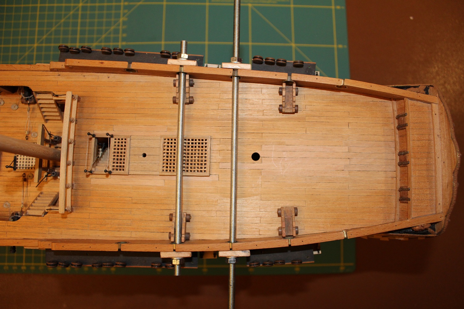
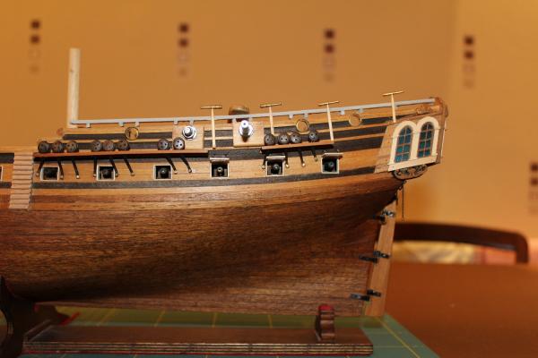
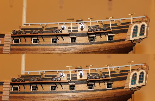
Before taking the next big step I decided to seek the opinion of Landlubber Mike and JohnB40 via PM. With their permission I am adding a slightly edited version of our discussion in to the log. (Me) I am after an opinion or two. I have tried out the studding through the gun ports to pull the bulwarks in to line. I only had 4 off M5 nuts so I could only set up two clamps. I have cut padding from some wood to avoid damage. I was expecting a lot of creaking and groaning as the 35 year old items were pulled towards each other, even a nasty crack as something let go. In fact nothing. The bulwark pulled inwards with the slightest of effort, which to me shows the weakness in construction that the Corel design has. I have added a photo of these in use: Before securing it I decided to see what it would look like with an open rail. I made a rough rail up from 2mm thick card, with some 2mm thick supports. I also added 4 swivel guns temporarily skewered on top of some cut back toothpicks. The barrels are Caldercraft 1:64 half pounder swivels. They are slightly too long but I think they look OK. The 2nd swivel from the right comes out at 5ft 3 inches above the quarter deck. Not too bad I think. The 2mm spacers give a scale 6 inch gap between rail and fixed bulkhead cap. The temporary rail, supports and toothpicks simply lift off as a single unit. I have edited the same photo to show what it would look like if I removed the existing fixed cap, reduced the height of the bulwark to the bottom of the walnut trim then added a lower replacement 2mm thick fixed cap. This would give a scale 12 inch gap. The circular port ring would protrude upwards more but this would be similar to the layout in the Lyme plans. I am trying decide which of these is the way forward. The latter looks better but will involve a lot of surgery plus towards the stern the current fixed cap disappears behind castings. What do you think? I have added a comparison photo as well. (JohnB40) Howdy Ian, If it were mine I would go for the bottom idea. You could go with half circular or what it degree takes on the gun ports to blend them into the plank-sheer cap and railing uprights. I could never really tell from the Lyme plans whether the ports were full or half circles. I don't know if the rail has to run parallel to the cap,I don't see why it couldn't be higher at the quarter deck end,getting lower as it goes stern . I could be imagining this but I think I have see it that way on some of the in the NMM. (Me) Thanks John. Looking at the contemporary models some have the open rail remaining parallel to the cap, others have the quarter deck rising (to stern) more steeply than the cap, but the rail is parallel to the deck, so the rail and the cap converge. If I reduce the height of the cap I can mask the step down ahead of the castings behind (or by) the rear most swivel support. (LandlubberMike) Hi Ian and John. Wow, what a dilemma. I've been pouring over the Lyme and Unicorn plans, your pictures, and our prior build log conversations on the errors of the Corel kit for the past couple of hours. On the Lyme plans, the open rail looks like it runs parallel to the cap. In both sets of plans, the rail at the stern is above to top of the transom cap, so I think you're on the right track. The issue as we both noted on our logs is that the upward sweep of the quarterdeck towards the stern is too steep on the Corel kit. So, to be more true to Chapman and the Lyme plans, technically the quarterdeck should be less steep, and the port holes should therefore come down. I think the swivel gun posts should be the same height from the quarterdeck as you move towards the stern. http://modelshipworld.com/index.php/topic/6223-hms-lyme-1748-1760-by-landlubber-mike-kit-bash-of-corel-unicorn-scale-175/?p=202411 http://modelshipworld.com/index.php/topic/515-hms-unicorn-by-ianmajor-corel-scale-175-1748-to-1771/?p=202353 I tend to agree that the lower image looks better, but I think where you are running into trouble is with the quarter galleries. The top decoration from what I can tell should end just under the cap (from Chapman and one of the Lyme plans), or possibly end right at the top of the cap (as with the other set of Lyme plans). Since you can't change the level of the quarterdeck at this time, I was originally going to suggest maybe reducing the height of the quarter gallery windows by maybe a row of panes, which would lower the upper stool and decorations and get you closer to within the cap. But, that will probably look a bit awkward given that those windows would then not match up with the windows at the stern. The alternative then is to go even higher with the cap at the stern, but that would run into issues like height of the swivel guns, the upper bulwarks hitting too high on the transom, etc. So this is the point where I suggest something and duck and hide. Have you considered doing some surgery at the stern? I wasn't sure if that was what you were intimating earlier on your log. I don't know how much work this would take, but if you were somehow able to get the quarter galleries closer to that last gunport, the quarter galleries (as well as the transom) would drop, and the upper decoration of the gallery stools from my rough measurements would be within the cap. This would (1) be more true to the ship plans where the aft edge of the quarter galleries should fall inside the fore end of the rudder, (2) align the stern galleries and quarter galleries, and allow you to build some nice looking upper and lower stools to fit things together nicely, and (3) perhaps move the transom forward a bit, allowing you to take out the flag lockers and have an easier time with the tiller. The tricky part would be to figure out how those changes would work relative to the stern counter, but maybe you could make it all work with minimal impact to the counter and the hull planking (hard for me to tell from the pictures). I just throw that out there because it seems like you are not particularly satisfied with the stern and flag lockers, and a while back you seemed to resign yourself to cosmetic changes to the galleries to make it work. If you're still not happy, maybe it's worth taking a look at whether you could redo the stern? You did magnificent work opening up the waist, so the stern might not be so bad. (Me) Mike, John, Thanks for the input. Some good stuff here. You have given me a lot to think about. I like the idea of revamping the stern but when I surveyed the situation I decided that I would probably badly disrupt the hull planking in the process. Opening the waist was simply (!?) a matter of cutting an (almost) rectangular hole in the deck. Altering the stern at this point, desirable as it is, I fear is beyond me at this point in construction. I am now favouring lowering the fixed cap and having a deeper gap between it and the rail. If I can lay my hands on a suitable piece of wood I will replace the brass port rings with wooden ones which I will stain black. On the swivel height relative to the quarterdeck, yes the height should be fixed. I was wondering however about reducing the height of the swivels gradually towards the stern. The idea being to mask the step rise of the quarterdeck. Probably a non-starter though. Whilst thinking this through I am working on the tiller/rudder head cover. I think I have solution. Being built in to the flag lockers it will be a flight of fancy. It will match the width of the Lyme cover but the height and length will be greater. Perhaps I could put a grill on the front to lock up mutineers! (Landlubber Mike) Ian, I feared that surgery on the stern would be too much at this point. Lowering the cap would be a good solution. Couple of extra points: 1. On the swivel gun posts, do you even need them? Could you just do the rail and leave it at that? Seems like that might give a cleaner look. If you do go with the swivel gun posts, I think gradually reducing them, even though inconsistent with the height of the quarterdeck, would be a good approach. 2. That would be fun to build a mini-prison on your ship. 3. For the port holes, a year ago I emailed Corel to ask for a extras because I couldn't find them on websites like Cornwall Model Boats. I offered to pay, and Corel sent me a set for free - an incredibly nice gesture! So, maybe consider asking them so that you have matching port holes. I'm sure they'd get a kick out of seeing that you are working on their kit for 40 years.

-
Mike, A brave decision and one that Mark Taylor will empathise with. As I mentioned elsewhere I think your work here is not wasted. If you go for scratchbuilding the Lyme from the NMM plans you will achieve two of the top goals of scratchbuilding - accuracy and originality. You certainly have the skills to achieve this.
-
Dafi, From your photo you appear to be "going at it hammer and tongs" (or at least pliers) which is an old UK blacksmithing related phrase meaning going at something really fast and hard. I am intrigued by the character watching over you past your left ear.
-
Bring it on! Totally agree with you Mike. You should produce a good result with these modifications. The captain won't be happy because it reduces his cabin from the Corel ballroom to a realistic size.
-
Mike hasn't been on line for few weeks so may not see your request straight away. I have the plans but mine are the original 1974 ones. The Diagrams you specify I don't think have changed. I can easily scan them in and get them to you. I will drop you a PM to compare notes and arrange - no charge, I am sure you would help me out. BTW - Did you know that in the UK one of the most frequently used excuses given by children for not having handed their homework in is "My dog ate it"!
- 51 replies
-
- 2
-

-
- first build
- corel
- (and 1 more)
-
Mike, That is looking really good. As you say the staining allows the planking to show up well. I think this will really become apparent when you photograph the ship outside in the daylight which gives a nice defused light. I keep reading about folks using the Byrnes table saw. I would love to have one but sadly can't justify it.
-
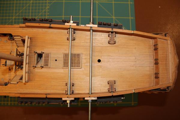
John, The idea of using threaded rod through the round gun ports is excellent. Obvious really - and as is often the case things only become obvious when someone points it out! I have M5 studding to hand and tried a length through pairs of ports. It clears the gun carriages (just) and with the deck furniture removed (not fixed yet) I can get studding through all five pairs of ports. I can use metal washers with plywood pads underneath to spread the load. I will try this approach and if all else fails back to plan B and rebuild the bulwarks! As you noted the Corel plan has 4 round ports per side, Chapman shows 5 per side and on the Lyme plans 6 per side.
-
Peter, Mike, thanks. Yes I do tend to think in terms of brass and steel rather than wood. I have measured up. The rail width is 5mm, the width of the part below is 3mm. The smallest wooden doweling I have is 2mm (toothpicks) which would be strong enough. The problem I foresee is that drilling a 2mm hole down in to a 3mm wall will only leave 0.5mm of meat on each side. There will be a fair amount of sideways thrust on this doweling so I fear it may burst out of the wall. 1.5mm brass would give little more meat so would probably have the same issue. 1mm brass would probably not be strong enough and would bend. I need to get these bulwarks corrected else when the swivel guns are fitted the supports will have a distinctly drunken air. I have looked at the stern area of the Lyme, Guadaloupe and Winchelsea plans and think more drastic action may result. I will of course move my recently made binnacle, wheel and capstan to a safe place. For those of a nervous disposition - look away now!
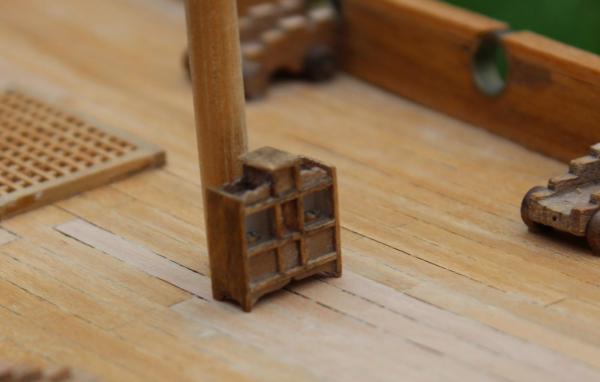
-
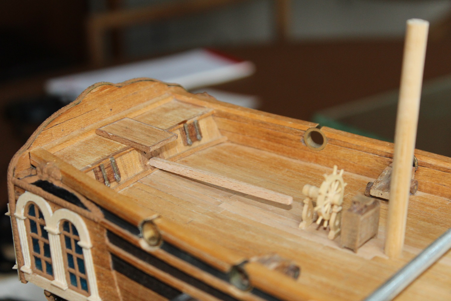
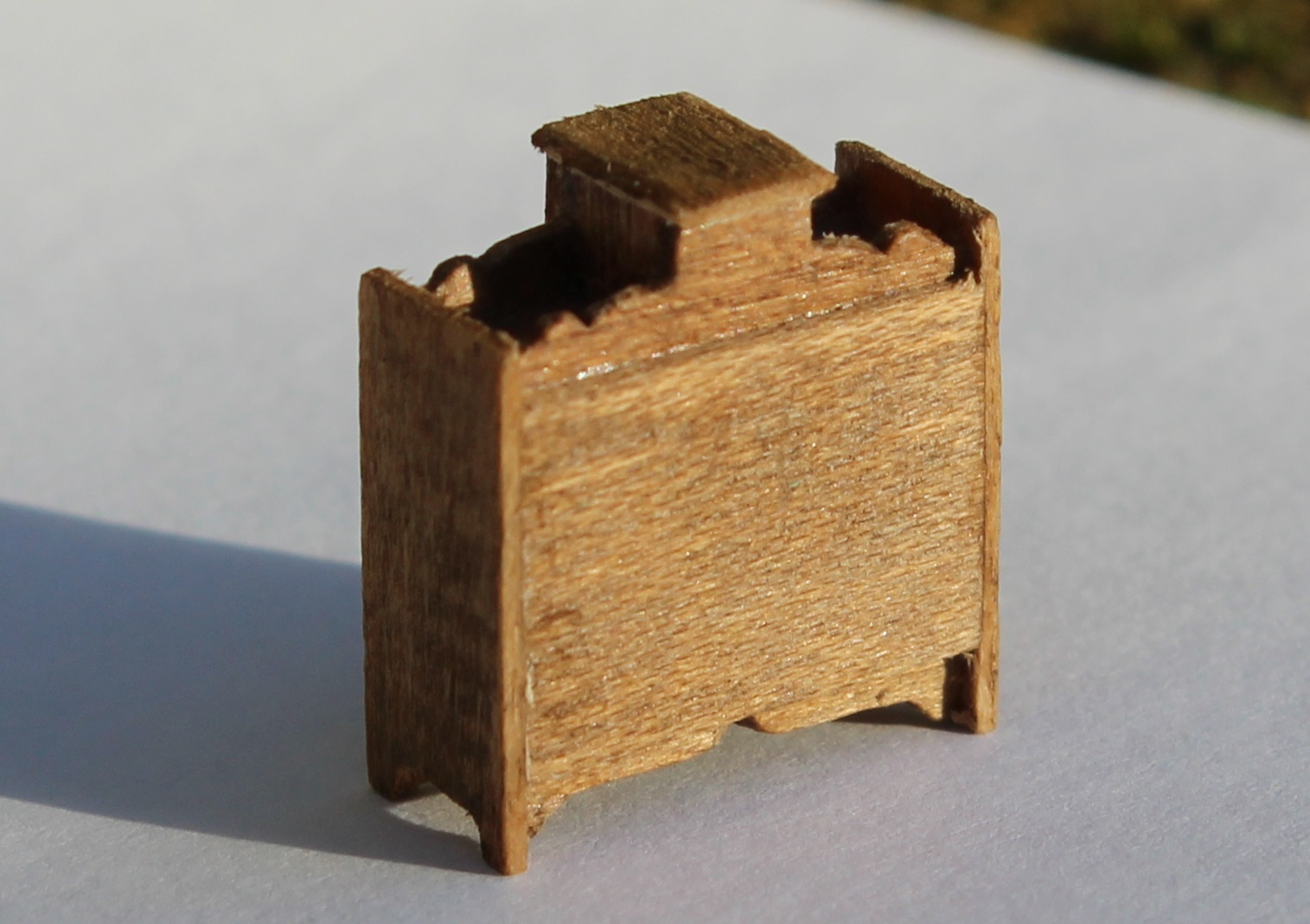
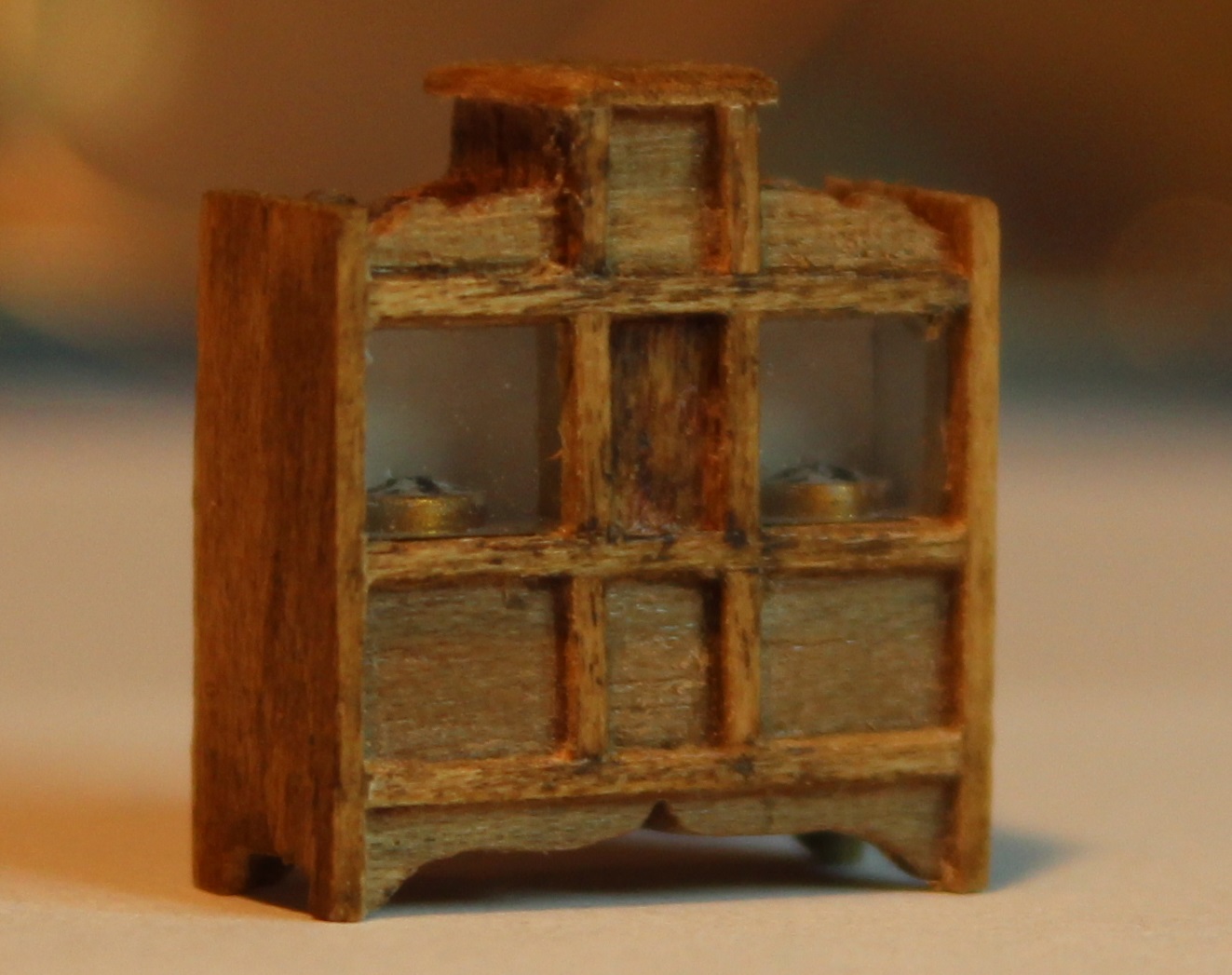
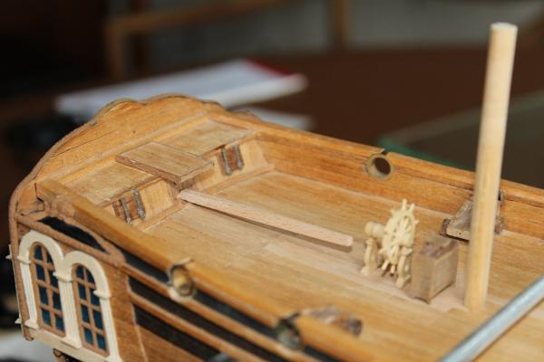
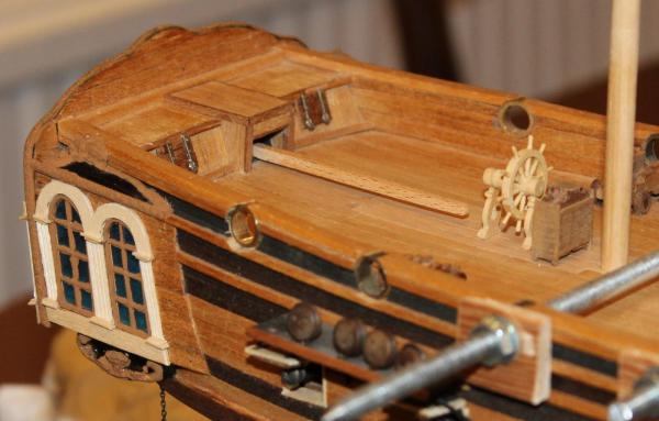
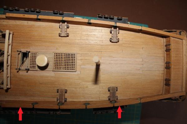
Mike, I think it was George Bernard Shaw who said "England and America, two people divided by a common language." I have used Crystal-Clear for glazing. It produces good results in small windows. I understand that it is basically diluted PVA glue with some additives. I found it best for circular windows such as port holes. My next challenge is to make the tiller housing around the fantasy central flag locker. This is my starting point: I believe I have a way forward but it is going to be awkward. I want to add an open bulwark rail along the quarter deck to include swivel gun supports. I am trying to decide whether to do it before or after I rig the cannon and wheel. There is a problem. There is little strength to hold the bulwark vertical because the poor method Coral specify for the existing bulwark consists of a layer of base wood planking (with grain and joints horizontal) and two other decorative layers each with grain and joins also horizontal. The picture is looking down on the quarter deck bulwarks. The starboard bulwark is not bad but the port bulwark over the last few decades has splayed badly outwards (note the area between the two red arrows). This is exacerbated by the existing rail being weakened by the holes for the brass port rings. I think I need to do something about it now rather than later because it will take a fair bit of grunt to straighten it up. Anybody got any views on how to secure it? I am leaning towards pushing it upright, holding it in that position, drill down the centre (say 1.5mm diameter) then gluing in reinforcing brass rods. Hum.

-
Mike, Perspex is fairly easy to work with. I managed to keep the "glass" surface clear whilst working on it. If it gets scratched I think it needs polishing powder to bring the clarity back up. It is possible to smooth the surface by lightly playing a flame across the face but I don't think that gives a crystal clear appearance. I am thinking of having a crack at a lantern based loosely on Dan Vadas' method from his Vulture log. He made a plastic plug on which to build up the lantern then removed and discarded the plug. I am thinking of making a similar plug out of Perspex, polishing the machine marks off the faces, then building the lamp frame around it keeping the Perspex as part of the lantern. I will see how it goes. The piece of Perspex I have is A4 size plenty long enough for a row of windows. It would be possible to mill grooves in to the face to set the wooden glazing bars accurately in to place. The method I used on the binnacle is ideally suited to the more open "Victory" type with three panes of glass fore and aft. I cut and shaped a block for one of those but didn't persue it. Perhaps I should.
-
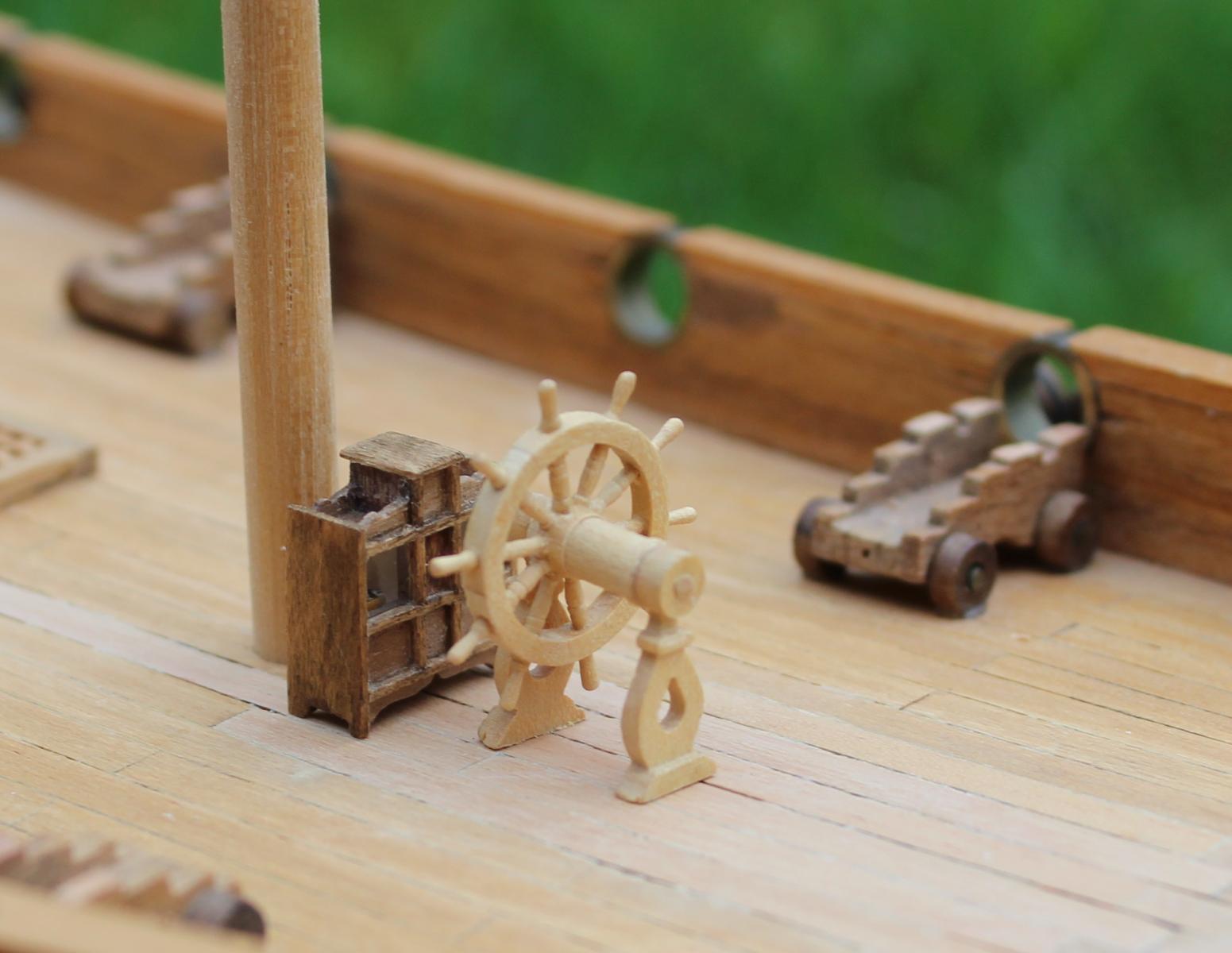
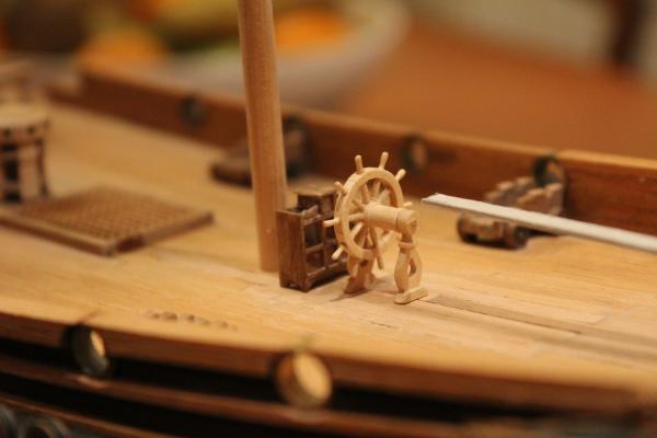
Grant, Nenad, John, Piet and Mark, many thanks for the encouraging words and thanks for the likes. Piet, it was not my being ingenious. As ever I am simply stealing other peoples ideas. When it comes to modeling I don't believe I have a single original idea in my head. Nenad, you may be interested to know that I "laid the keel" of this Unicorn in Karaburma in 1975 - a location you may be familiar with. And John a Happy New Year to you and your family. Well for a short time today the rain stopped, the clouds parted and we got some weak sunshine low in the sky. So I tried taking photos of the binnacle outside (when the wind stopped blowing it away ). Hopefully these will look better. The binnacle by itself casting a long shadow. Dust is already collecting on the "glass". The rear of the binnacle showing the plain panel that I fitted. Looking this closely it looks like it has been constructed from old floor boards and plywood lifted from a building site! I took a couple more photos on the deck. The first shows the front of the binnacle quite nicely. The second gives some interesting comparisons, the size of the binnacle against the cannon, and how rough the walnut of the binnacle is against the boxwood of the wheel. I got the photos just in time. The sun has gone, the clouds have closed over and it looks like it is going to rain - again.

-
Gaetan, I am left speechless. I don't know which of the photos is my favourite, they are all stunning.
- 728 replies
-
- 3
-
-
- le fleuron
- 64 gun
- (and 1 more)
-
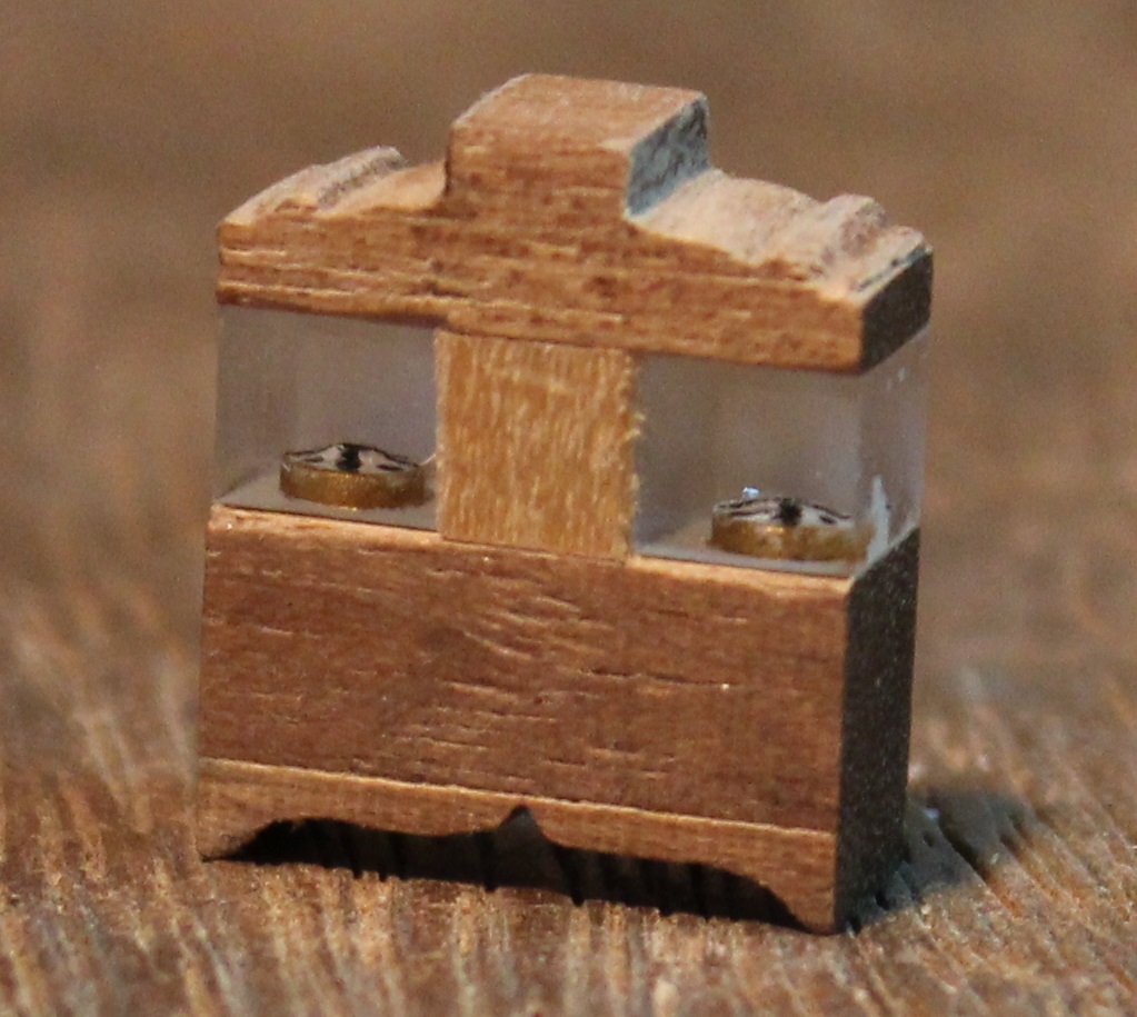
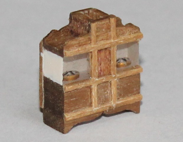
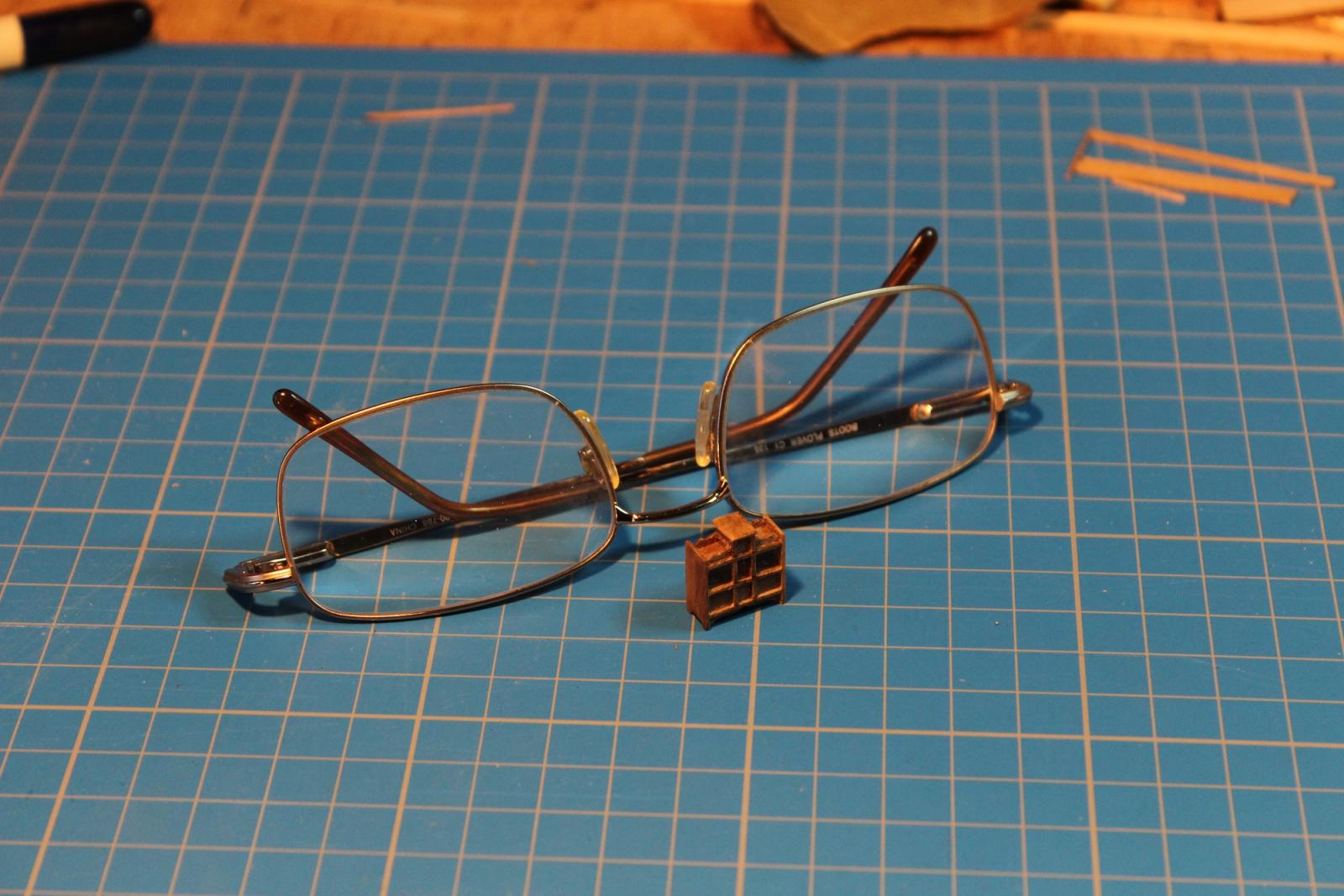
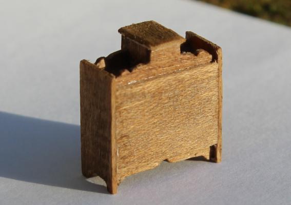
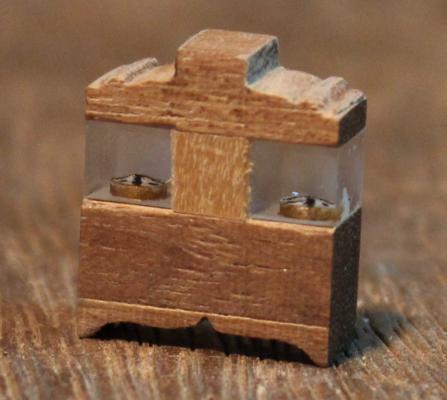
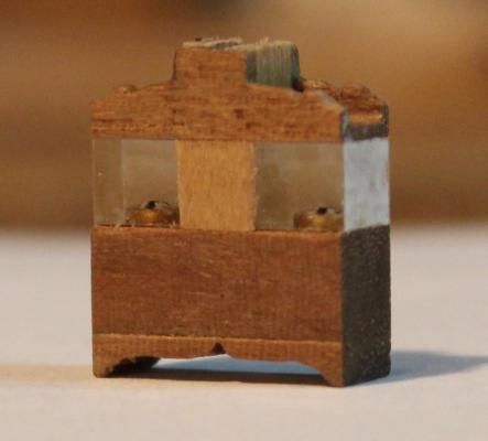
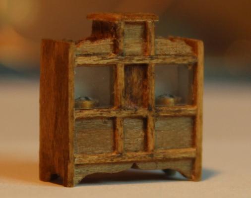
To clad the binnacle I used walnut. Not ideal but it is what I have. I stuck a 5mm square block on top and another one on the bottom of the perspex. Since the perspex was only 4.5mm thick I was able to leave a slight overhang top and bottom at the front. I milled some walnut sheet down to 0.5mm thick and a piece of this was stuck on the front of the perspex to represent the cover over the lamp. The last block was a piece of 2 x 5mm walnut stuck on the bottom . The next photo shows this. It appears on the screen about 8 times full size so rather exposes the irregularities in the surface of the wood! The top and bottom blocks were shaped.... ....then the whole was put in the mill to cut out the centre of the top block. I then added the sides of the lamp flue cover. The following photo reveals a couple of issues. The first is that when I filed up the flue cover I made it about 1mm too narrow. As a result when I later added the glazing bars and other detail the middle section was narrower than the sections either side. Doh. I decided to live with that. Tut tut. The second is the walnut sheet is noticably lighter than the walnut block. I tried "American Walnut" coloured stain on a test piece, but when I tried it on the actual binnacle it looked too red. It also highlighted the grain in an undesirable way. Instead I tried some Raw Umber water colour paint which seemed to give the right result. It doesn't coat like oil or enamel paint and is nearer to a stain. It should be OK once protected with varnish. Next was the glazing bars which I made fron 0.5 x 0.5mm walnut which I cut from the sheet. Ideally these should have been of a smaller cross section but the walnut tended to disintegrate below this size. The binnacle on the Amazon model has a plain back. So on mine I made a plain cover from some of the 0.5mm sheet, the edge of which is just visible on the left in the next photo. I had intended to detail the three panels across the lower front but decided against this. I would have used thick cartridge paper for this. The centre panel was too small and just doing the outer panels would have looked odd. The structure was completed by adding the end panals and the top . The bottom of the end panels was shaped to represent the legs. The next photos shows it complete. I will try to get a better photo in daylight. The binnacle is not as blotchy in real life as the photo suggests (honest!). Will try tomorrow when the weather conditions will hopefully be less grotty. A shot of the binnacle next to my specs for scale..... ...and a final shot showing it posed next to the wheel on the ship. I will fit some rings to the binnacle later which will be used to "secure" it to the deck.


-
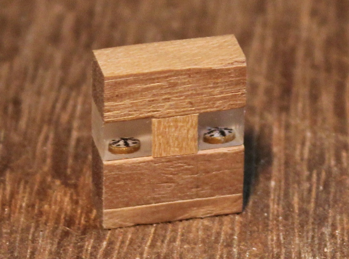
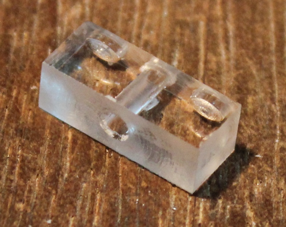
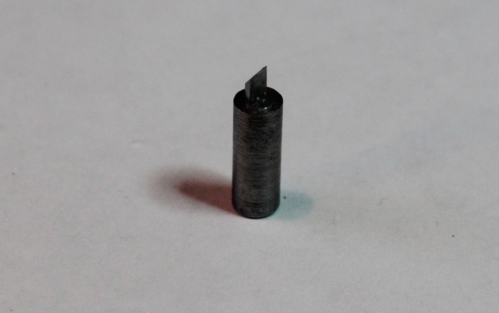
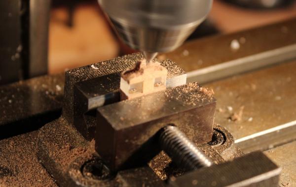
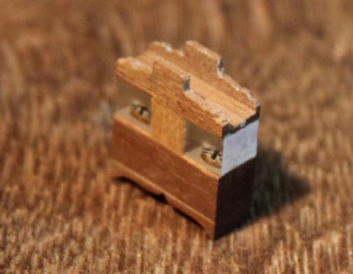
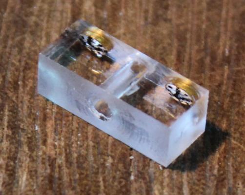
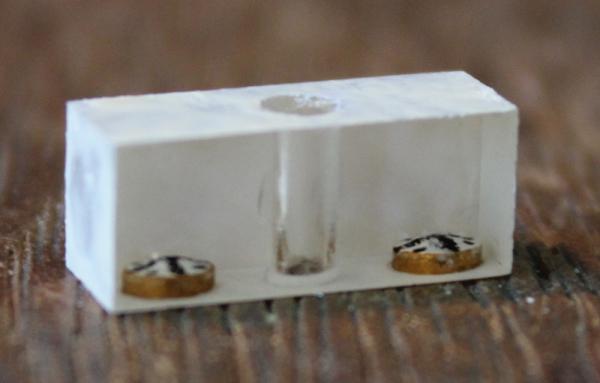
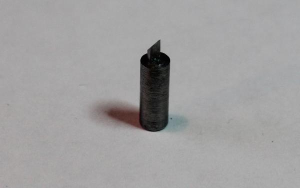
Well now - time to tackle the binnacle. I decided to make the "Amazon/Chuck" type. When considering the construction method I thought back to a colleague of mine from 30 years ago who made models in his lunch breaks in the office. He was a war gamer and used to make vehicles that were small enough to fit several in the palm of his hand. One of these was a single-decker bus which had flush glazing and inside were seats. He explained to me that the seats did not actually exist! The bus was carved from a block of perspex. The seats were cut out of the block as holes then the holes were lined with paint to make the seats look solid. I decided to try this for the binnacle. I cut out a blank from 5mm thick perspex (which was actually 4.5mm thick). I faced it square and down to size in the lathe (I said I was lazy! ). The block was now 5mm square by 13mm long. Through the centre I drilled a 1.8mm hole. This allowed me to hold it with a cocktail stick whilst working if required. (A miniature LED could be used in it for lighting.) I bored two 2.6mm flat bottomed holes 0.6mm deep in the bottom of the block to represent the compasses. To bore these holes I made a "D" bit. This is simply a length of steel turned down to the correct diameter, the end is filed to half its diameter (making in "D" shape cross section) then the end is beveled to make a cutting edge across the centre. The perspex block ended up like this, having cleaned up the inside faces of the holes with solvent. Next to give the compasses some body I painted the inside of the holes. Normally when painting a compass you paint the face first then add the characters on top. In this case, the characters were painted in the bottom of the holes first, then the sides of the hole were painted to represent the brass case. Finally the face colour (white) was painted in. Photos of replica binnacles show the insides painted white. So I painted the faces of the block that would later be clad with white paint. Again have to think everything in reverse.

-
Moonbug, thank you for your kind words. From what I see of your Santa Maria it should be me being envious of your skills not the other way around. Unlike most of the MSW members I don't have very good skills with basic tools and I am also very lazy. So I use the lathe and milling machines to do all the work and make life easy for myself. I love your Santa Maria - I have a soft spot for this ship since it was the one that my Grandfather intended to make during his retirement but never got the opportunity. I still have the 1950's plans which would not pass muster compared with current information. Thanks also for all of the likes.
-
Mike, That looks a very neat piece of work, particularly around the rabbet.
-
Piet, Looking good. I am going to rig my Unicorn as per Lees. What you refer to as "kruishouten" he refers to "kevels" and what you refer to as "hoorn klampen" he simply calls "pin rack on mast"(!). I am interested in your experience with these items because it will probably help me. By the way, if Troy has two left hands when it comes to tools then he should do very well (I am left handed ).
-
Peter, Nice work. Did you hone your bulkhead correction skills on the Unicorn? I certainly did!
- 207 replies
-
- 1
-
-
- billing boats
- cutty sark
- (and 1 more)
-
Hartmut, That is absolutely lovely. I am very jealous of your work.
-
Ed, and a Happy New Year from me. Very nice work. I must invest in some decent CAD software to help with the machining!
- 3,618 replies
-
- 3
-
-
- young america
- clipper
- (and 1 more)
-
Wow Hartmut, that fireplace is stunning. Brilliant work.
-
Alexandru, your pictures tell a very interesting story. Excellent work.