HOLIDAY DONATION DRIVE - SUPPORT MSW - DO YOUR PART TO KEEP THIS GREAT FORUM GOING! (Only 53 donations so far out of 49,000 members - C'mon guys!)
×


ianmajor
-
Posts
784 -
Joined
-
Last visited
Content Type
Profiles
Forums
Gallery
Events
Everything posted by ianmajor
-
 Gary, I will follow your progress with great interest. As well as the books and his log I think you will find Ed himself to be very supportive and helpful.
 -
Moonbug, A fabulous result. It is set off beautifully by the stand. You must be very proud of it.
- 274 replies
-
- 4
-

-
- Santa Maria
- Artesania Latina
- (and 2 more)
-
Piet, An interesting set of colours on that chart. Vermillion was the pigment used for painting the buffer beams of UK steam railway locomotives due to its bright nature - a sort of predecessor to dayglow colours. I understand that it was not used for more general locomotive body colour due to the pigment being very expensive. So - was no expense spared on 17th century ships?
-
Of course it was Marc Brunel, father of Isambard Kingdom, who invented this block making machine. Marc was a Frenchman, his wife English, so IK can be regarded as a fine example of Anglo/French co-operation.
- 728 replies
-
- 2
-
-
- le fleuron
- 64 gun
- (and 1 more)
-
Hartmut, I have looked at this photos 4 times now and each time they look even better.
-
Matrim, I will be following this with interest.
-
Spyglass, thanks for that. I actually found watching that video pleasantly relaxing. It also brought back memories from 30 years back when I worked and lived in Abu Dhabi for a couple of years. Each year there would be sea races from the port area past the Corniche. There were canoe races where each canoe had 120 men with paddles and two steering oarsmen. These were very fast vessels which I believed were originally used by pirates to attack sailing ships becalmed in the Gulf. For me the high spot of the day was watching the large sailing dhows being raced. These of course were lateen rigged. They were sooo graceful. Unfortunately having sailed south away from the port they then returned to the port by being towed backwards by power boats. It looked so undignified - I chose to look away at that point. It has probably all changed now. That is a good point you raise and probably exposes my lax use of terminology (especially on subjects off which I know little ) . Tacking does indeed involve frequent changes of direction. I should really have spoken of change of direction. I based my comments on an entry in a blog that used to exist for the ill starred Bounty replica. In it the chap who was captain at the time referred to a problem that occurred with the mizzen yard where there was a "miscalculation" somewhere. When they swung the yard towards vertical to move it to the other side of the mast the lower end fouled the deck and they could not complete the movement. Ooops. Well, helped by an exchange of PMs with Mike I have decided to mount the wheel behind the mizzen mast. Stand by for some destruction - I may be gone some time! ...
-
Thank you Ed. No need to appolgize on the binnacle info , the level of your contribution to my model making via your logs is incalculable.
-
Thanks for the links Mike. Two stunning models. The Pandora was fabulous - I think its scale is slightly larger than ours! The Pandora binnacle I notice was as per the NMM/Victory version having 6 panes of glass and no mid shelf with the compasses on the bottom. Could be an interesting challenge to produce something small (1:75) with so much glazing and with no internal strengthening that would not collapse. Worth a try for the fun of it! The binnacle will fit behind the mast. The Corel layout behind the mizzen is more generous than the Lyme plan. I have seen models with the wheel behind the mast and the binnacle in front. The compasses would have been visible around the mast - just. I am also intrigued with the arrangement behind the mast with lateen rigging. My understanding is that when tacking the mizzen yard had to be swung vertically so that it could be moved to the opposite side of the mast. Must have been quite a dance with the steersmen. Presumably in Lyme/Unicorn times this would not be an issue where the mizzen yard was retained but the sail was lashed down the mast (I have forgotten the right word - getting old).
-
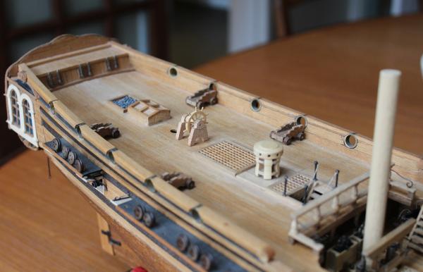
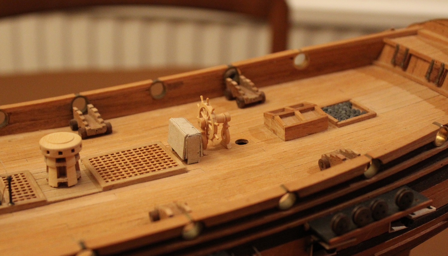
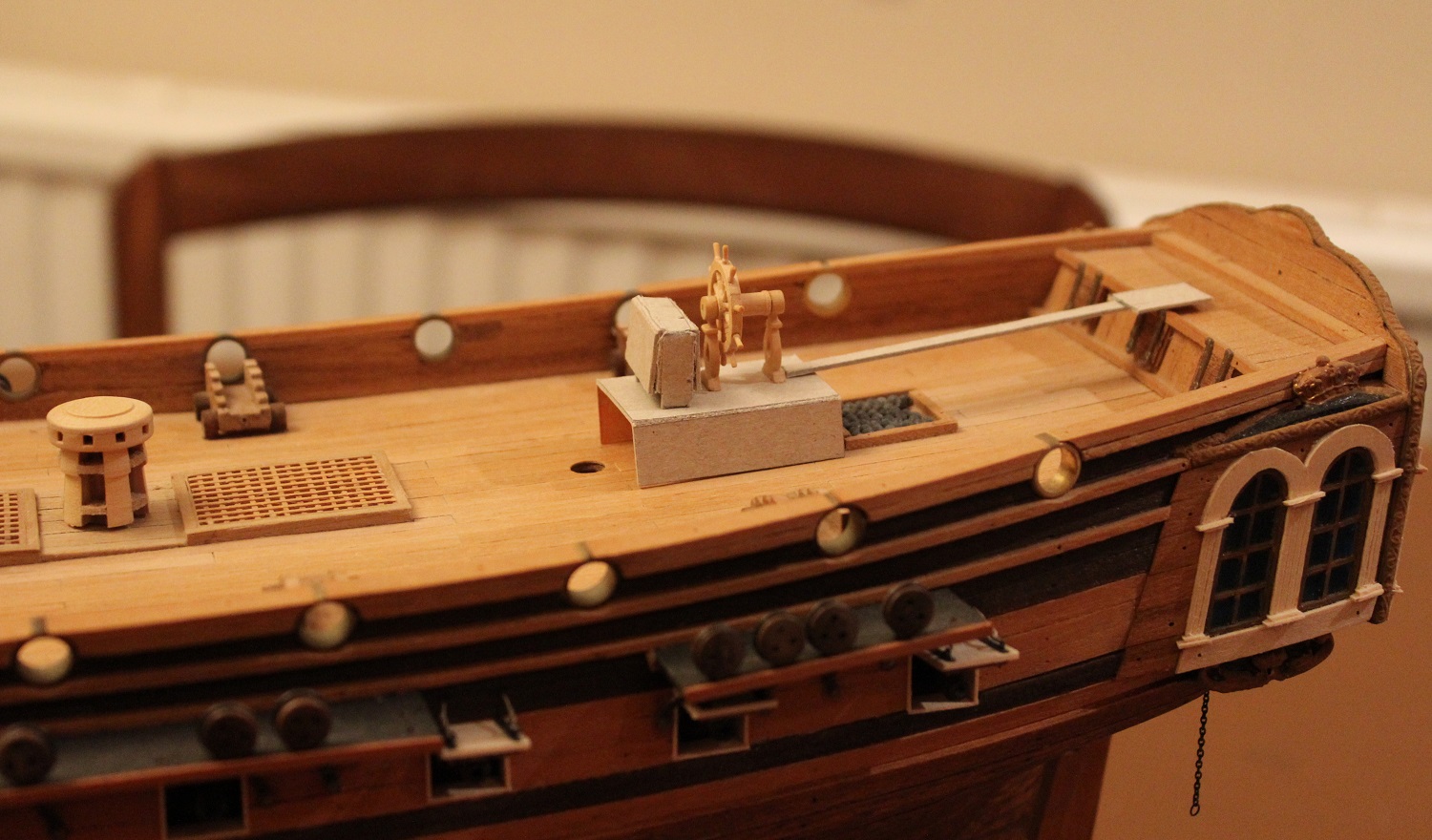
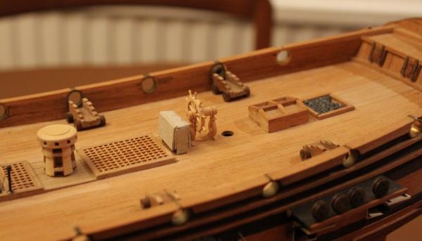
The second question is the position of the wheel and binnacle relative to the mizzen - should they be in front or behind? I made a (very) rough card mockup of a binnacle and tried it and the wheel in front of the mast. There is sufficient room for them. If I adopt this position I will possibly replace the Coral toplight thingy with a grill and get rid of the fanciful shot holder altogether. The alternative is for the wheel to be behind the mizen as on the Lyme plans held by NMM. The distance on the model from the mizen to the transom is 120mm or 30 scale feet. On the Lyme plans it is 25ft which scales to 100mm in 1:75. Some of the additional space on the Unicorn model is taken by the (unlikely) Coral flag lockers. The flag lockers cover the rearmost two bulkheads that stick above the quarter deck level. Getting rid of these lockers completely, therefore, is a non starter. The Lyme tiller protrudes forward from the cover by 15.4ft which in 1:75 is 61.5mm. I made a card outline of the tiller and cover and tried it with the wheel and binnacle behind the mizzen (I also made a temporary card tunnel over the toplight to allow the wheel to stand in the correct place albeit too high). Again it fits. I could make a tiller cover that is integrated with the middle of the flag locker with the shallow interior painted black to mask the fact that it doesn't go anywhere. If I do this I am not sure whether to move the cannon forward. Does anyone have any thoughts on this? I have other deck furniture to make before I have to finally decide.

-
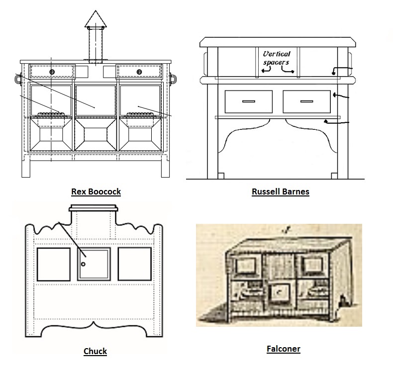
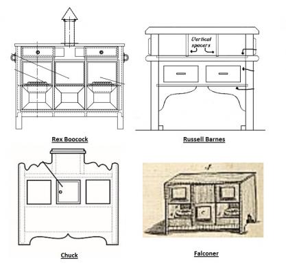
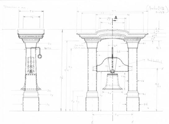
A couple of questions have now come up relating to the wheel and binnacle that I must answer in the next few weeks. The first question is on the design of the binnacle. No help from Coral since they don't supply one with the Unicorn. The different British designs of double compass binnacle of which I am aware are summarised in the next image. In it I have taken the front views from various plans. The first diagram is by Rex Boocock. The full version of his plan can be found in the MSW section "Furniture and Fittings" here It is the type that is on Victory. There is also a model of this type at the NMM. There are differences twixt the model/Victory version and the plan. One is that Rex has one pain of glass per compass facing the stern. All the other panels are blank. The NMM/Victory version has 3 pains of glass both fore and aft. A second difference that would not be noticeable at this scale is that Rex shows a mid shelf in which the compasses sit. There is no mid shelf on the NMM/Victory ones, the compass units appear to be deeper and sit on the bottom of the cabinet. The second diagram is by Russell Barnes and is part of his practicum on making a battle station. This is in the MSW section "Model Ship Articles" here . Actually I just checked and the binnacle plan part is now missing (ex MSW 1?). I have a copy of this plan if required. I can't find any contemporary models or pictures that match this design. Perhaps someone can enlighten me. The third diagram is by Chuck. This is in his Winchelsea log here Siggi52 has made a nice version of this for his Dragon (see here ) . There is a contemporary model at the NMM of the 1780 frigate Amazon that has this type. The following is a detail from the NMM photo. The full photo can be see here . The fourth one is taken from the top right corner of plate 1 of "An universal dictionary of the marine" by William Falconer (1732-1769). This was taken from the copy held by the National Library of Australia (see here ). Apparently this was the copy owned by the ship's carpenter that accompanied Cook on his last Discovery voyage. It has similarities to Chucks plan though the compasses are sat on the bottom. There is no apparent flu for the oil lamp. If anyone has any input on this it would be appreciated. At this time I am leaning towards the Amazon/Chuck design for the Unicorn.
-
Thank you Mike and Piet and thanks everyone for the likes. Mike, I am cutting up an old rule. It was given to me by my Grandfather when I was quite young so it must be more than 70 years old. It was slightly damaged on one edge and was no longer any use as a rule. I was keeping it for sentimental reasons but decided that once I shuffle off this mortal coil my children would probably bin it. Since I dedicated this ship to the same Grandfather I decided that using its wood for items of deck furniture was highly appropriate. Rules of that age are generally thicker than more modern ones. It is 6mm thick. I have a wooden scale rule (also damaged) which I bought in the '60s which is only 4mm thick. I think the rule is English boxwood, but what ever it is, it is very nice to work - a real pleasure compared with the mahogany and walnut that I have.
-
Hartmut, Excellent work. It is a very attractive interior.
-
Ed, Stunning work. You make it look so easy - and then I try it - gulp.
- 3,618 replies
-
- 5
-
-
- young america
- clipper
- (and 1 more)
-
Alexandru, Your work is beautiful - as ever.
-
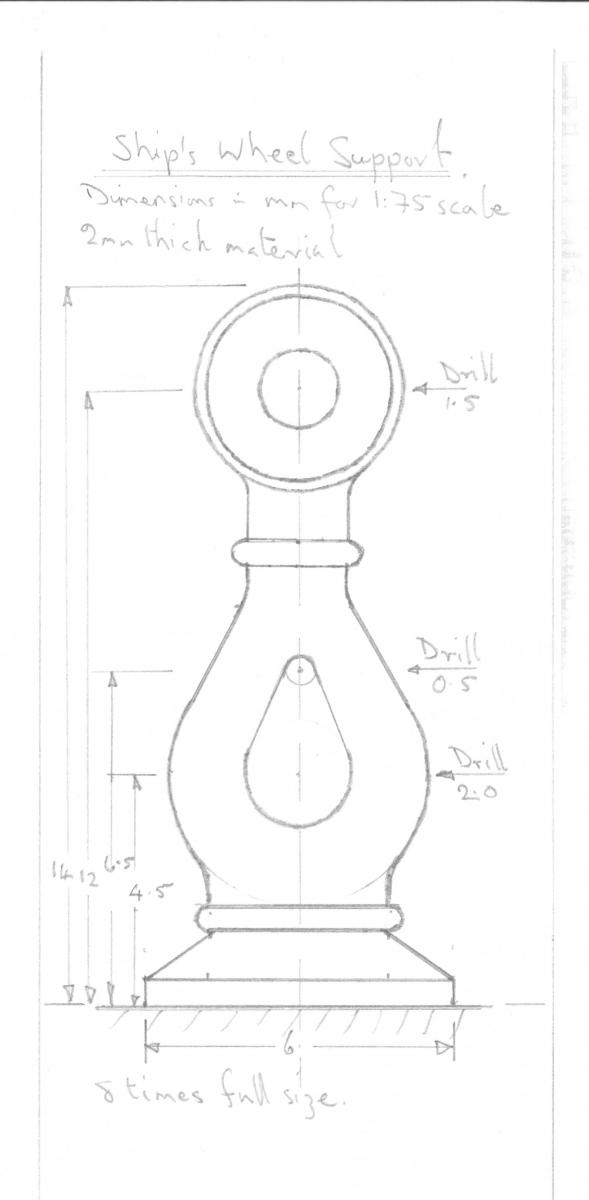
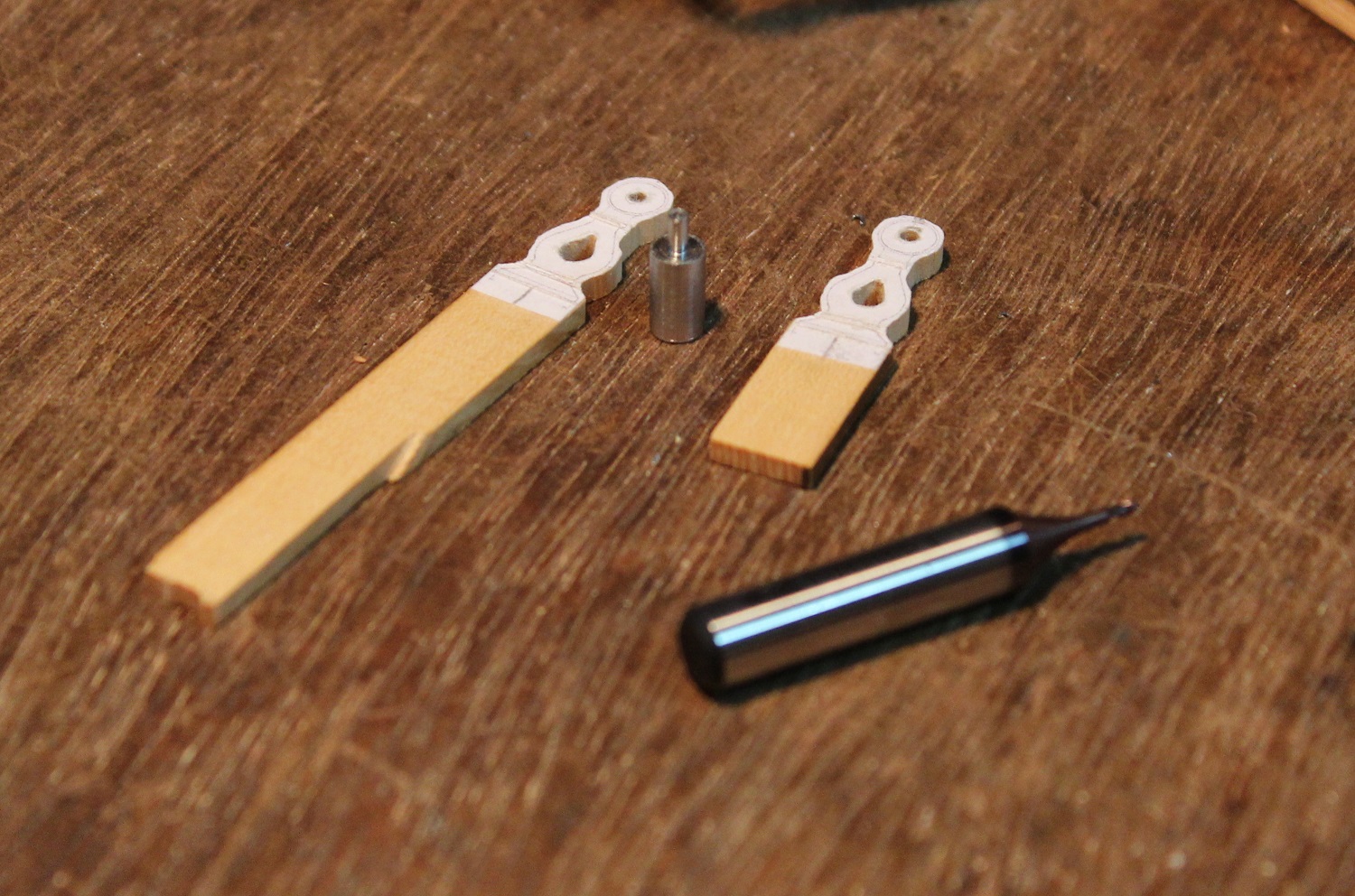
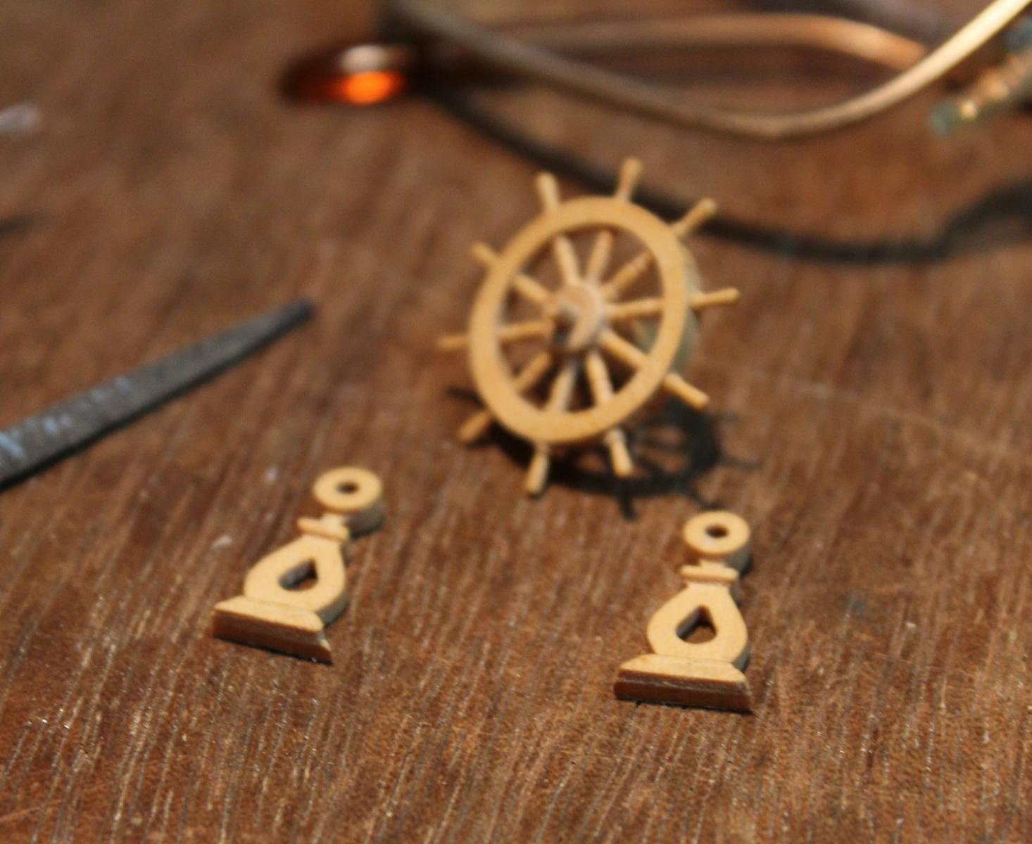
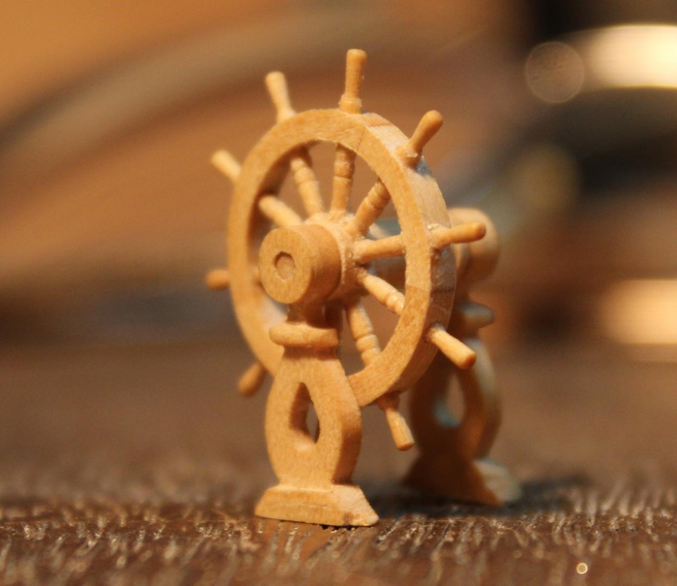
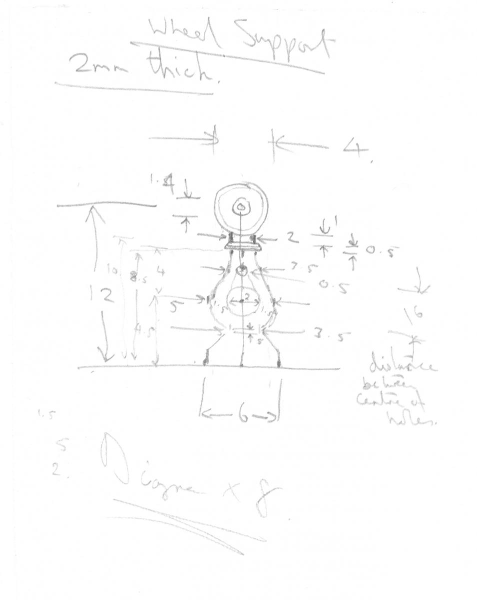
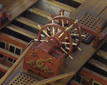
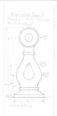
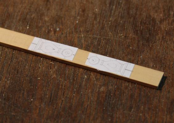
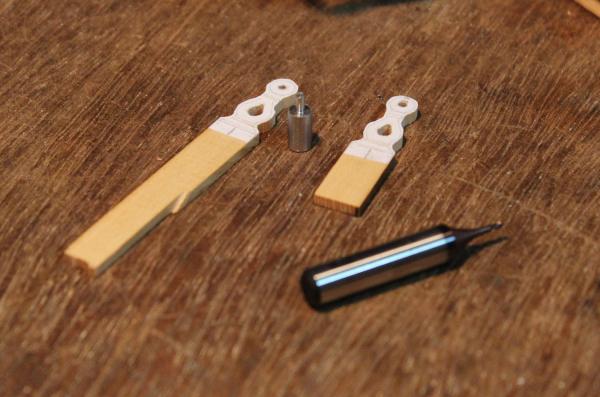
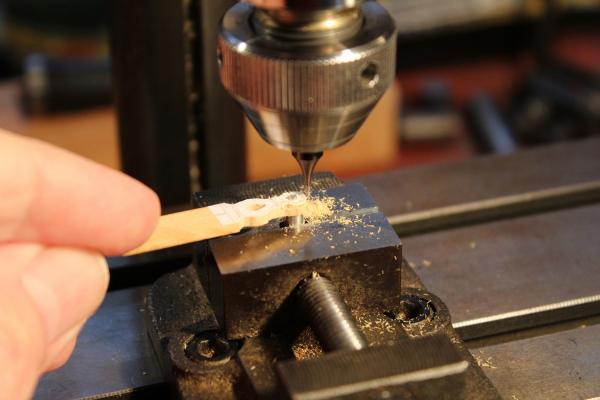
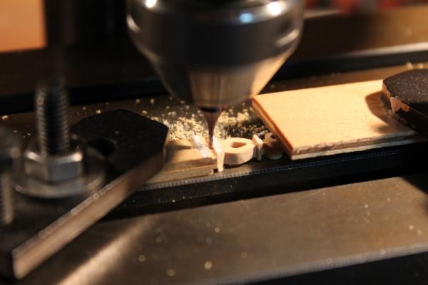
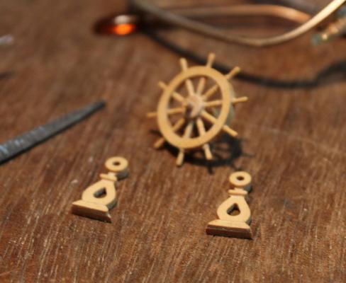
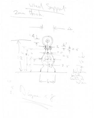
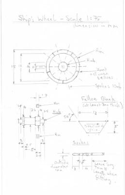
I turned to the wheel supports. I looked at a variety of sources. I took inspiration from the entry in EdT's Naiad log <here> along with the picture of Guadeloupe. The first thing I did was to draw a diagram of a support 8 times full size (attached - click on it to see detail and use if you wish). I have included my original free hand diagram here which has more dimensions on it than the clean version. Two copies were then printed reduced to the required size and pasted on to a piece of box wood that I had milled to 7mm / 2mm cross section (as per EdT's method). I drilled the 0.5, 1.5 and 3mm holes in each support then using a fret saw cut out the central teardrop shaped holes. The supports were then roughly fretted out. I turned a filing button 4mm in diameter with a 1.5mm stub. This is in the middle of the next photo along with my 1mm mill bit. The button was clamped vertically in the "V" of the machine vice on the milling machine. Each support was mounted (one at a time) via its 1.5mm hole on the stub. This allowed the mill bit to be advanced up to the support and by swinging the support blank from side to side to shape the head. The two supports were glued back to back and their outside shape produced by hand filing. They were then clamped to the mill and the front profile was milled, first one support and then flipped over to do the second. The supports were cut to length, checked for square then separated and cleaned up. Finally a close up of the completed wheel in its supports - it shows the flaws up in a cruel way. It's confession time again. When reducing the diagram on my printer I used a 9% size setting. What I did not notice was the printer software accepted the 9% then quietly set it to 10% (obviously the minimum). Later when working on the support it looked too long. It was - by 2mm. So rather than ditch it I modified the base design on the fly. It is still a little too tall but hopefully no-one will notice.:-) I will now make card mock ups of a tiller and binnacle to try them with the wheel for size on the quarter deck. This will help me decide on whether to clear the area behind the mizen and to fit a visible tiller.

-
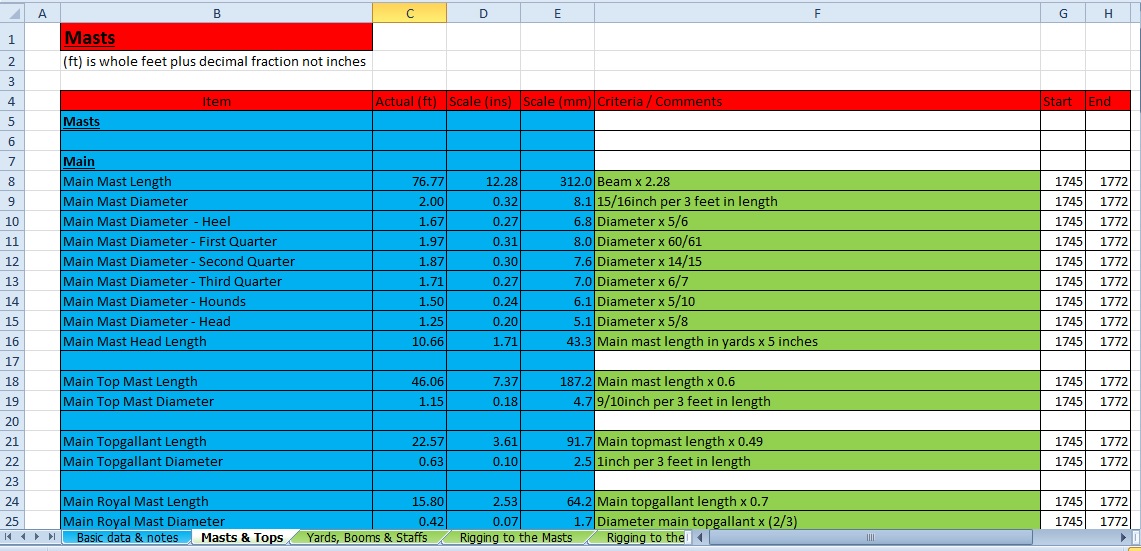
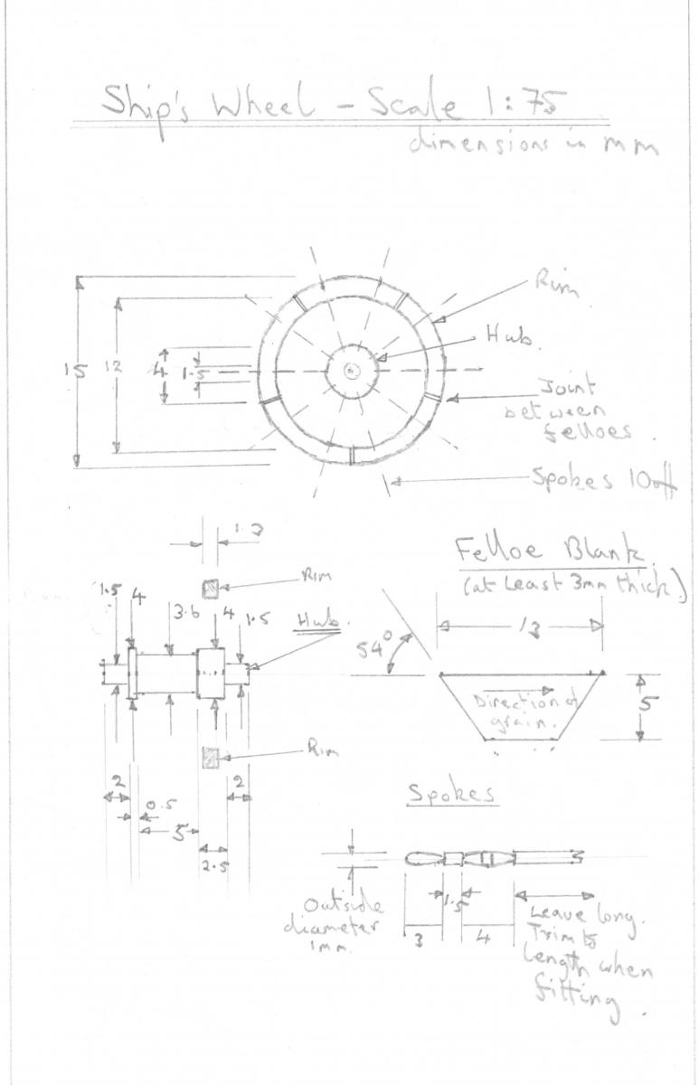
Mike, Ed, BE, Thank you. I am stunned to receive such kind words from a group of people who's work I greatly admire and I shamelessly copy. Thanks all for the likes. BE, Thanks for the info. I have been looking at both Steele and Lees. Steele I think is a bit late for the Unicorn though much will still be applicable. I will be preparing masts soon, in particular a couple of top masts to sit on the gallows. I am happy with the info I have on the lower mast tapers but am not clear on the top mast taper yet. So I am looking carefully at Lees, Steele and your build log to work this out. Mike, Go for it! I found making the wheel less daunting than some of the other jobs on the ship. If using individual felloes accuracy in making the angle of the ends is vital (54 degrees in my case) to ensure good joints. If the angles are wrong at best the joints will look bad at worst it will fall to bits. This was the only part that was tricky. Their length is not critical (within reason). They are wedge shaped if they are a little short they can be pushed towards the centre of the jig. If too long they will sit further away from the centre. As long as they cover the rim area this is fine. To make sure that the felloes were sitting correctly on the jig I drew radial lines from the centre so that I could line the end of the felloes with these. I also drew 2 concentric circles on the end of the jig to mark the inner and outer boundaries of the rim. If the circles were toally covered by the felloe blanks all was well.
-
Gosh Piet, that view along the quarter deck looks impressive. Lovely work.
-
Mike, Your planking is looking great. From your photos you seem to have a lot less clutter around you when model making than I do!
-
Piet, Lovely work. I am impressed that you are rigging all the cannon simultaneously. I only did mine in opposite pairs knowing that with my agriculturals any more in one go would have ended up in a mare's nest!
-
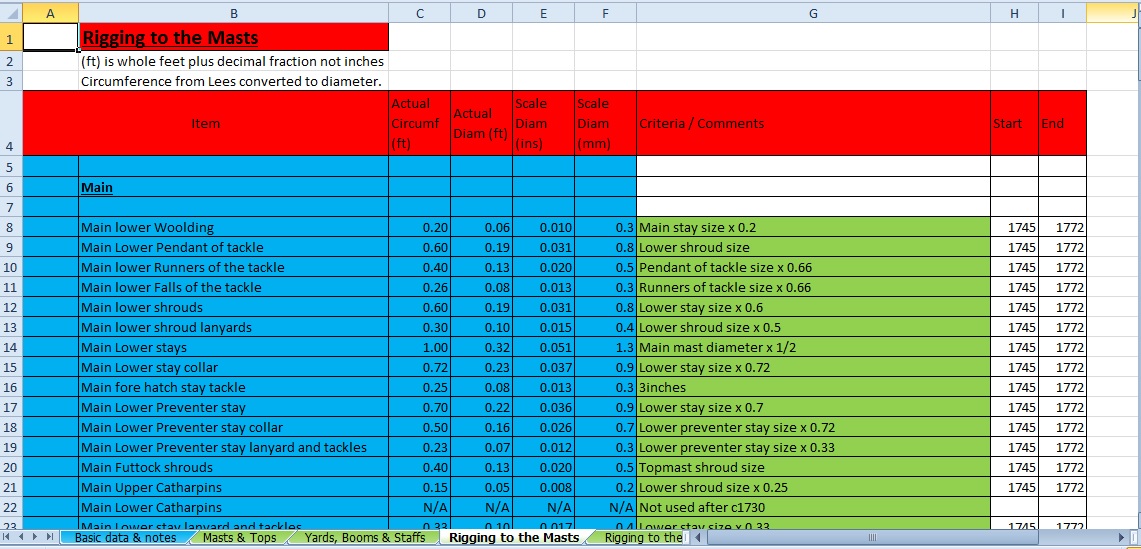
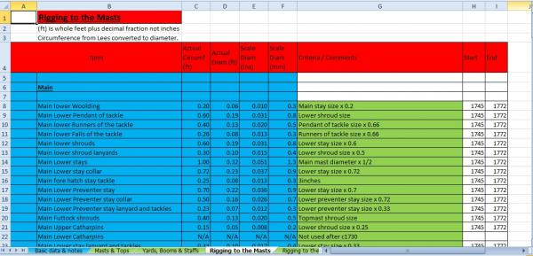
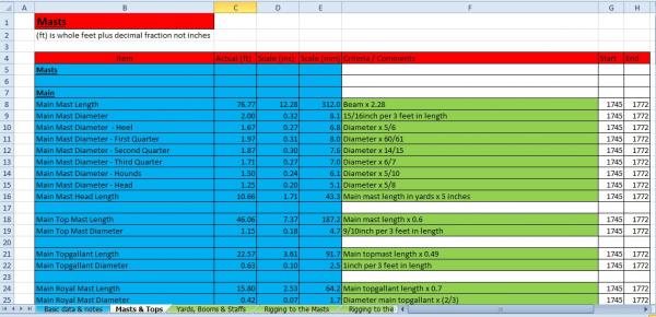
Here are my chicken scratchings for the wheel. My wheel looks a bit meaty so I think if I was repeating the wheel I would do the following: 1) Increase the rim inside diameter from 12mm to 12.5mm. The would reduce the rim depth by 0.25mm. It doesn't seem much but it would be a 16% reduction which would show. 2) Decrease the overall diameter of the spokes from 1mm to 0.8m. This would allow the rim width to be reduced to 1mm which would give a more delicate appearance. It would also reduce the crowding around the hub. I am also attaching my redimensioned belfry diagram to give as larger unit (diagram drawn by Rex Boocock) which I will be working on soon. Whilst I was semi hors de combat I did more work on my rigging spreadsheet. The source is Lees. Originally I was creating one that would cover all the sailing ships covered by Lees. It was feasible but would take a long time. I have restricted myself to covering 6th rate ships during the period covered by the 1745 establishment (1745 to 1772). This covers ships with a variety of beam sizes. I have used all the data from the Lees appendices and am now adding data from the body of the book eg the mast taper information. This is raising quite few questions in my mind. I am aware of the rigging spreadsheet in the MSW download area but that uses macros which are only supported by the full version of EXEL. I am a cheapskate ( ) and use the free starter version that comes with Windows which does not support macros but will handle formulae. Attached are a couple of example sheets from it. As you will notice there are loads of tabs on it. Click on each one to expand to see the detail. I will make the spreadsheet available on my share. If anyone is interested, drop me a PM and we can swap email addresses give access.
-
Thanks ZyXuz, John, Grant, BE, Piet, Ferit and Jason for your kind words and all the likes. ZyXuz, I have not heard from you for some time. How are you and how is your Unicorn? John, You raise a good point about the relationship between the wheel being behind the mizzen and the lateen rigging. I hadn't really considered it! Will the puppy be helping with the model making? Grant, I am just about to put my chicken scratchings in here. BE, The inspiration is normally from you to me! Piet, As you say it is nice to have the lathe and milling machine - I wish I could have afforded them when I was in my 20s. Actually I find the basic lathe and mill are fairly cheap it is the necessary extras that rack the price up eg 4 jaw chucks, collets and holders, off hand grinder etc. I don't have decent woodworking tools which makes life interesting in this game. Ferit, Did you mean painful rather than painstaking? Jason, I spend most of my time wondering how I am going to move forward!
-
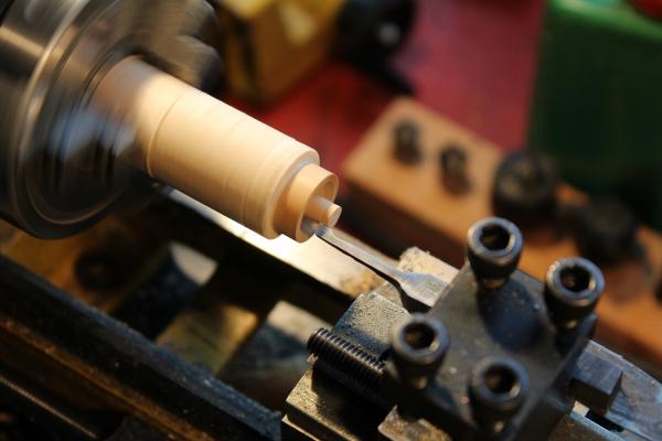
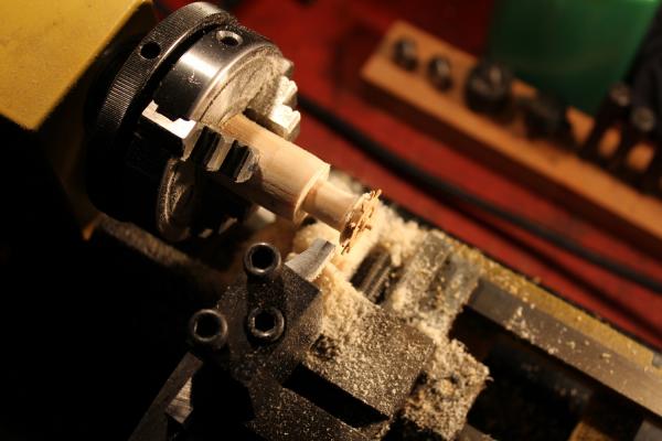
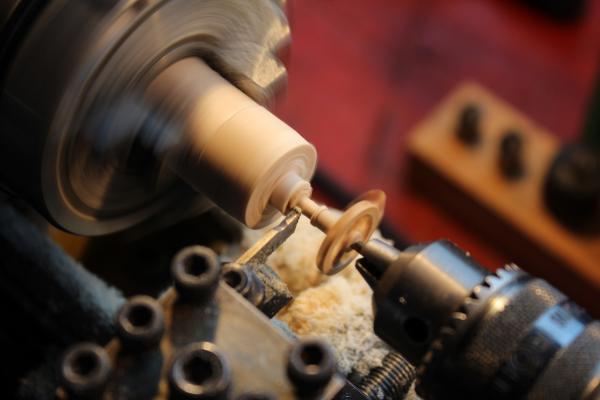
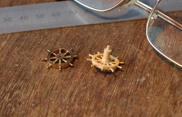
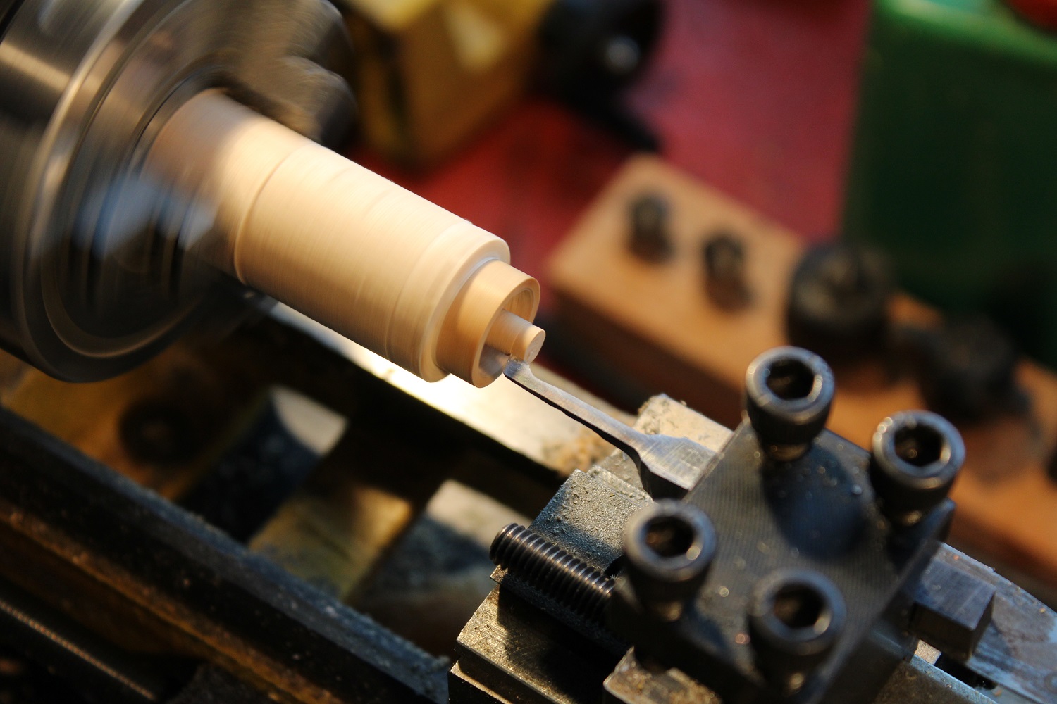
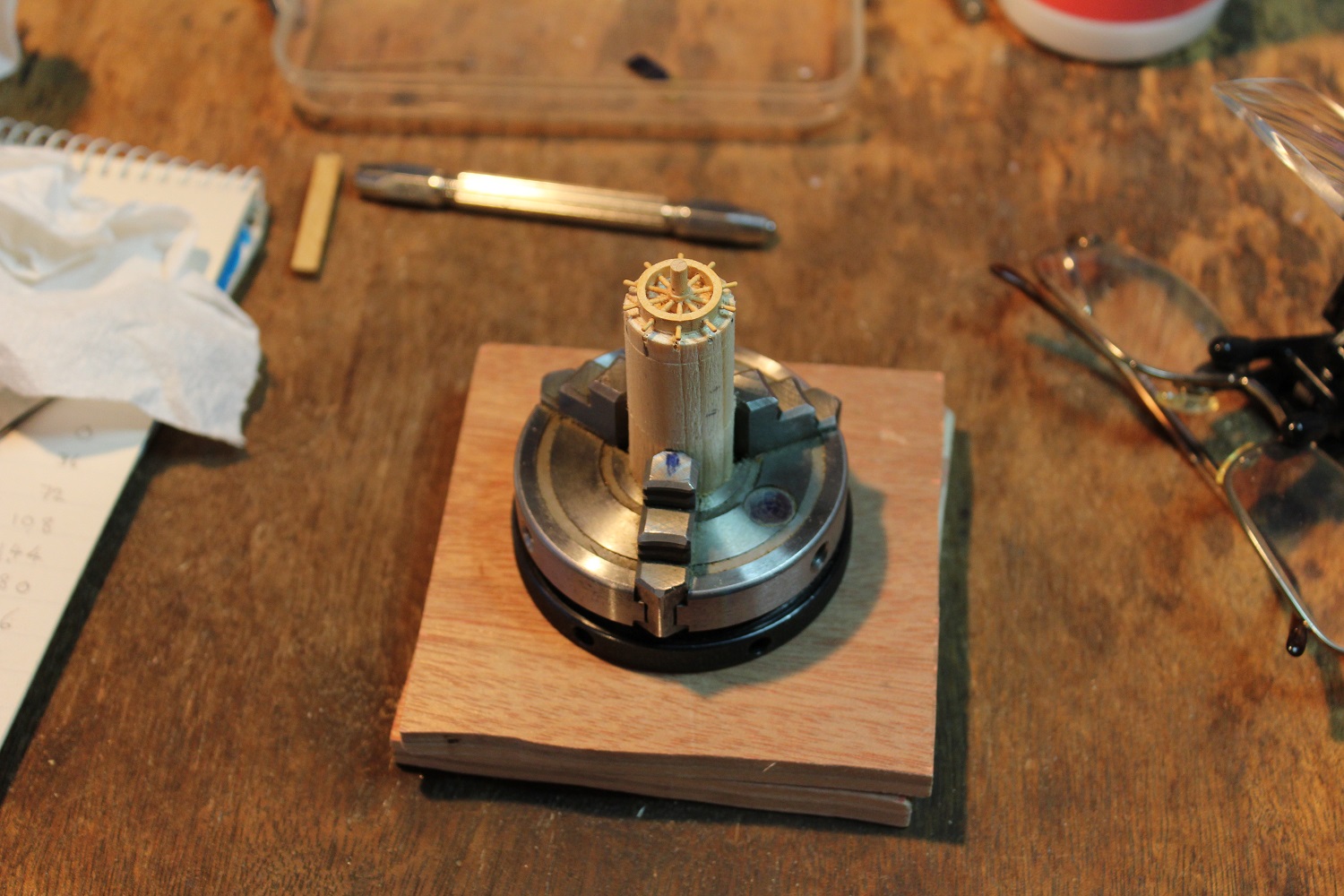
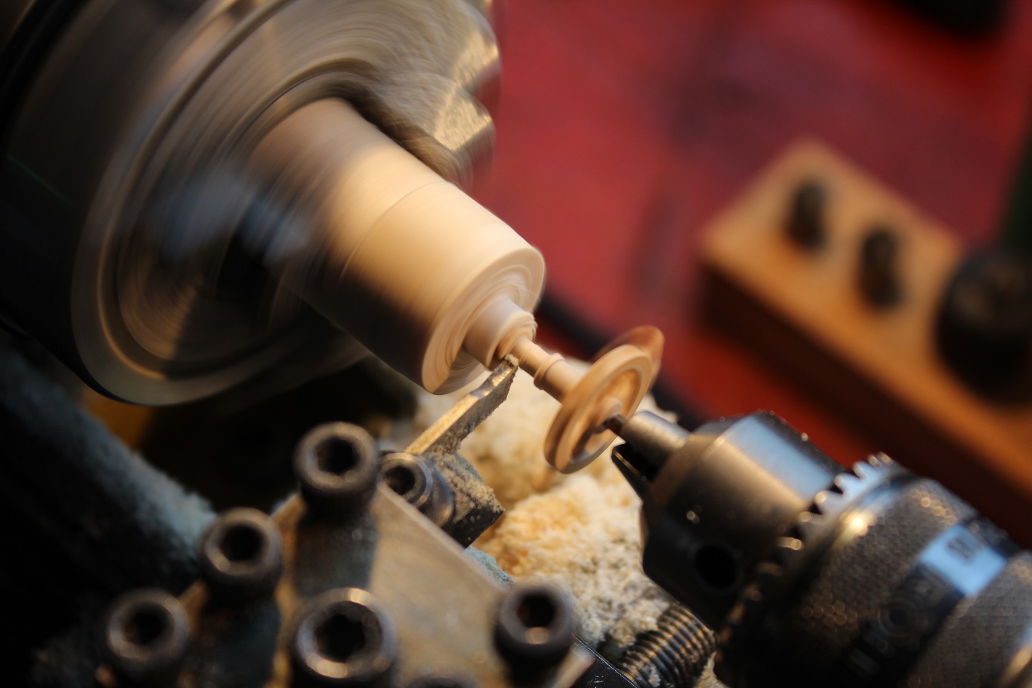
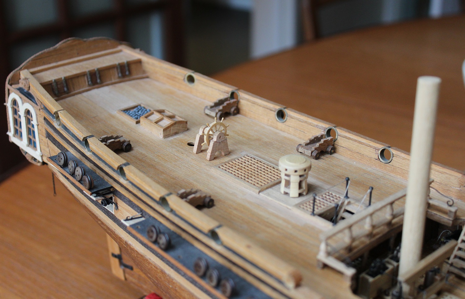
The hub was cut off to leave a stub protruding from the rim. The hub was then turned down to 4mm diameter. All the previous jobs on the wheel were done with standard lathe tools or tools that I hade previously produced. For this I needed a left handed, small boring tool which I had to grind up from a piece of 1/4 inch square tool steel. The boring bit had to be less than 3mm across and deep to avoid fouling the inside of the rim. The photo shows it in use - there is clearance angle between it and the work (honest!). The chuck was tranferred back to the dividing head on the mill and 10 holes were drilled around the rim. On to the bench where the chuck was mounted on its back on a couple of pieces of wood with central holes. With the chuck secure the spokes were fitted. I only drilled holes in the hub for the odd numbered spokes which were then fitted. When the glue was reasonable dry I drilled the hub for the even spokes and fitted them. The reason for doing this was that all 10 holes drilled at the same time would have burst in to each other. Back to the lathe for (in theory) the last time. I used a parting tool to cut a deep recess in the pine wood behind the wheel. This gave clearance space for a left handed tool which I then used to face the rear of the wheel down to its intended width. I then used the parting tool to expose the box wood core and to shape the drum around which the tiller rope will go. Finally I turned the rear pivot down to 1.5mm diameter and parted off. It would have been easier to turn the drun in front of the wheel but......(a confession coming up)....when I drilled the holes around the rim I used a 1.5mm bit at full reach to be able to drill through the rim and in to the hub. The bit wandered horribly leaving the holes all over the show. Fortunately the felloes were wide enough for me to have a second go with the bit retracted in to the drilling chuck. This gave better results (still a bit of wander) but the hub in front of the wheel now had holes in it which meant that part was no use for the drum. I examined the bit afterwards and found it was very slightly bent - not enough to be visible to the naked eye. The resultant wheel following cleaning up alongside the Corel wheel. Finally the Coral supports were used to see how it looked on the quarter deck. It is positioned in front of the mizen mast as per the kit instructions. I will make a new set of supports which will not be as wide as the Coral ones. I am contemplating fitting wheel behind the mizen mast along with a tiller above the quarter deck (as per the Lymm plans). To do this would mean:- 1) removing the toplight(?) and shot holder 2) move the 4 canon forward to the next ports 3) modifying the centre of the flag lockers to take the tiller. Hum....I wonder. If any one is interested I will tidy up my scrap diagrams that I worked from and will publish them here.