

woodrat
-
Posts
818 -
Joined
-
Last visited
Content Type
Profiles
Forums
Gallery
Events
Posts posted by woodrat
-
-
-
-
-
Thanks Carl. Nice web-site. Warning! Naming mediaeval ship types from different countries can do your head in.
Dick
- cog, mtaylor, CaptainSteve and 1 other
-
 4
4
-
Thanks, Carl. I believe they all had mainstays and in front of the sail. Some artists occasionally omit them even Carpaccio. I cannot conceive how the mainstay could be behind the sail. This must be an error. The best illustrations show a triple or quadruple mainstay which seems to be served or puddened to prevent abrasion on the mainsail.
Dick
- cog, mtaylor, CaptainSteve and 1 other
-
4
-
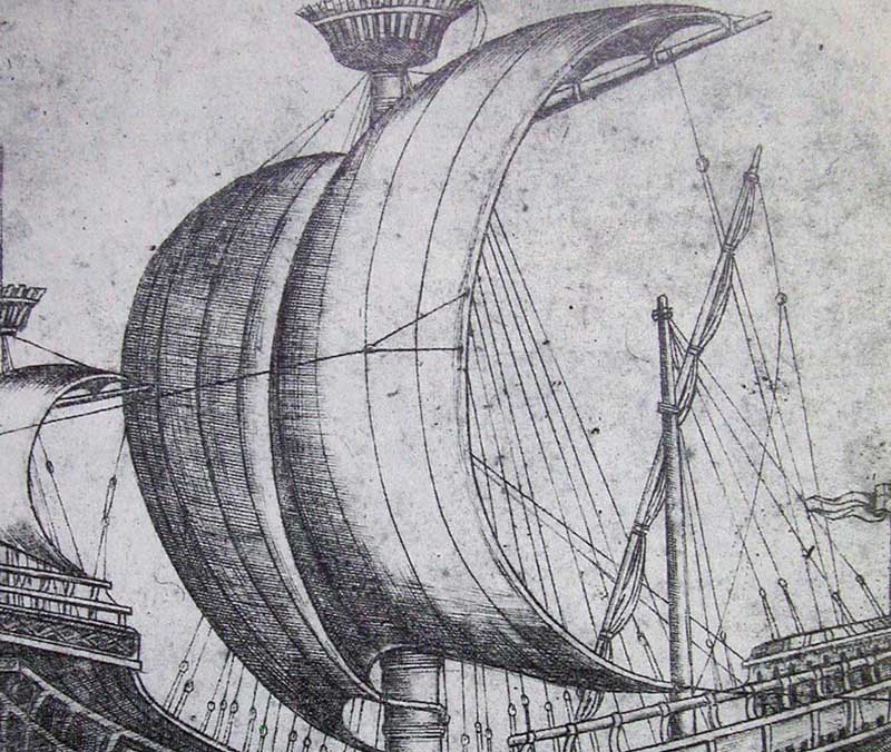
Spot on, Druxey. Many illustrations show this band from the midpoint of the foot of the sail around the mainmast. Some pictures show similar bands also from the bonnet(s). These are the reason that the centre of the billowing sail has a "cleavage". It may be that this was necessary a. to prevent the sail rubbing on the mainstay, b. splitting in the middle or c. I don't have a clew.
cheers
Dick
-
Thanks, Carl. Let me know if I am going too far astray.
Druxey, I am mainly concerned in producing realistic seam lines on the sail. Some illustrations show just longitudinal seams but many show a cross-hatched appearance. I like your idea of using dilute acrylic paint to stiffen the silk which may also be able to reproduce this appearance. I dont really want to print pictures on the sails although this would be good for flags.
Dick
- druxey, mtaylor, CaptainSteve and 5 others
-
8
-
Yes Mark and Carl. It sounds too risky to use a laser printer. However, sails are a long way off. I have to draw up a sail plan. Fortunately I will be able to stand on the shoulders of giants to do this. The important thing is to remember that this is a mediterranean vessel and should be rigged as such. Sailors in the northern seas did things rather differently. Consequently, I will not be using deadeyes for this vessel and the standing rigging will look strange to some. Dick

- CaptainSteve, mtaylor, JesseLee and 1 other
-
4
-
Have received my Silkspan and will experiment. Can you use a laser printer to print on Silkspan?
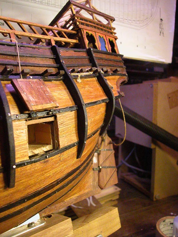
Here are some pics of the typical mediaeval arrangement of huge wedges for the mainmast at the partners and the reinforcing wooldings. There were many variations on this . I do not exaggerate the size of the wedges:

I need to go away and make some mediaeval blocks.
Cheers
Dick
-
-
Thanks, Druxey. I dont have the Sea watch Books but maybe I should. Silkspan looks a bit stiff?
Jesse, great idea with the balloons to give the sails a bosomy canopy. Presumably after drying you could cut the edges to shape. I am a long way from sails yet so I will look for more tricks on MSW as Steven suggests. Dick
-
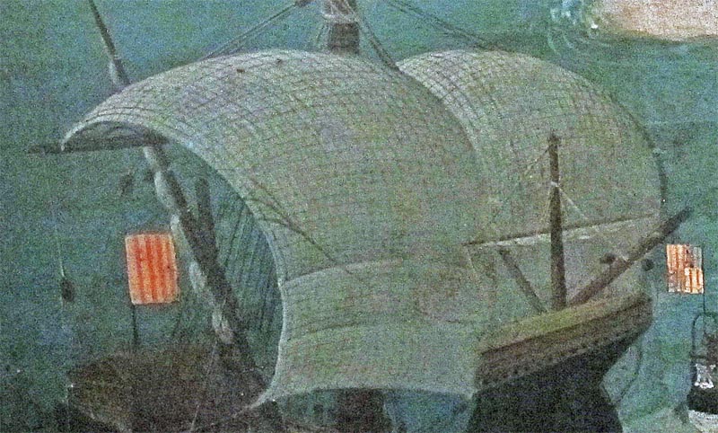
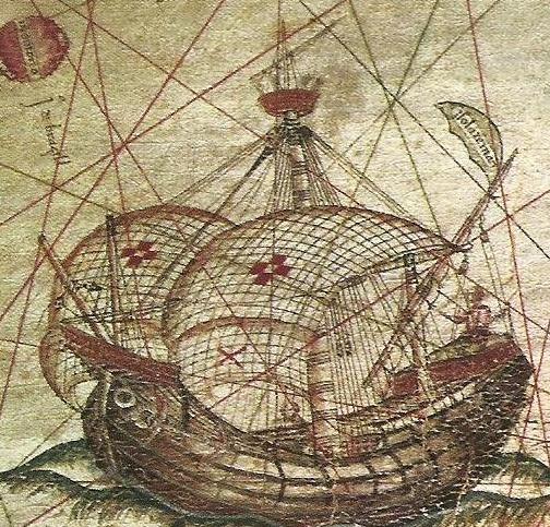
The problem is how to reproduce the bellied out appearance so characteristic of the carrack. It was thought by many experts last century that this was an exaggeration by artists but the ballooned out appearance is consistently shown. How do you cut the fabric to allow this? What fabric to use that would look like real canvas to scale. ? silk. How to stiffen it? glue hairspray plaster of paris. Is it all too hard to do?

Dick
- Archi, druxey, CaptainSteve and 1 other
-
4
-
Thanks Steven, Jesse and Druxey and to all of you who have been following this thread. Your support spurs me on. This largely completes the hull build and now I can tackle (pardon the pun) the masting and rigging. There are good research publications on mediaeval rigging and this should be fun. I am still tossing up whether to display her under sail or furled but am tending toward the former.
Cheers
Dick
- JesseLee, CaptainSteve, cog and 2 others
-
5
-
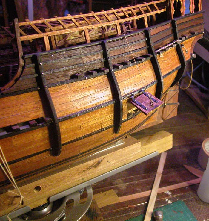
These are the ventilation scuttles to the aft quarters
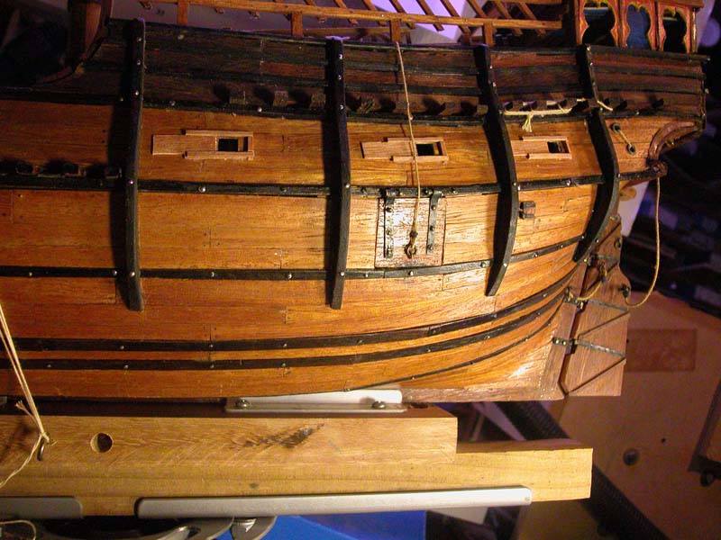 open
open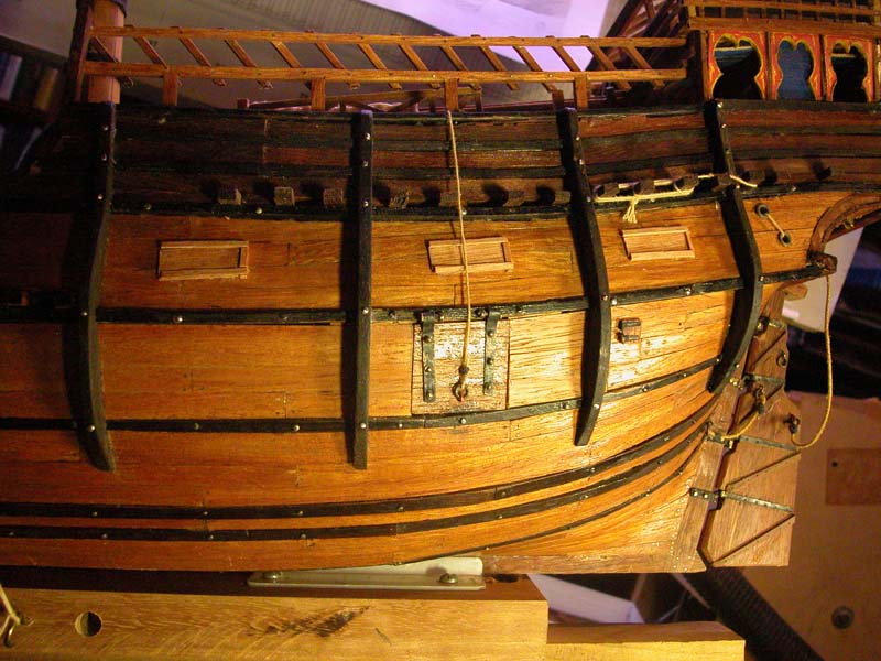 closed
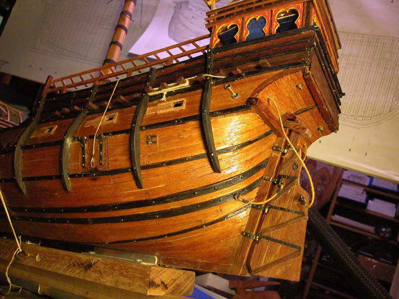
Dick
-
Thanks Steven and Carl. There aren't many but the illustrations I have managed to find show the port opening as shown and at least one shows a rope leading up to the rail. It would close by gravity and be probably held with a crossbar inside.To have it opening the other way would be hard to close by pulling from inside.
This drawing is probably of a model and seems have the port on the starboard side!
Thanks
Dick
-
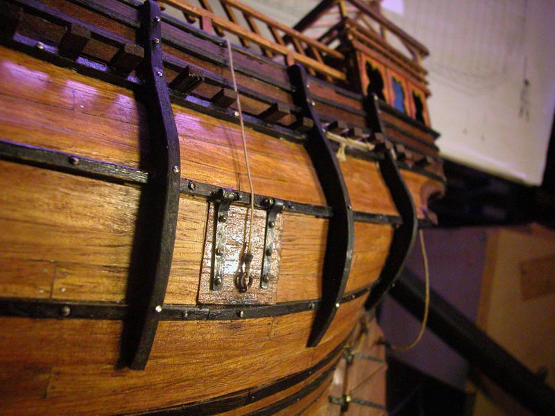
The loading port. The origin of the word port (opposite to starboard) is the loading port. In the days of the steerboard it is said that a vessel could not tie up at a jetty on the steerboard side for fear of damaging the steerboard and so the loading port was put on the opposite side, hence port and starboard
Many 15th century illustrations show the loading port.
Cheers
Dick
-
Thanks, Steven. I have cranked up the old ropewalk and hope to lay down some line soon. However there are a few finishing touches to do on the hull, namely the loading port and ventilator scuttles in the aftercastle.
Dick
- JesseLee, cog, CaptainSteve and 1 other
-
4
-
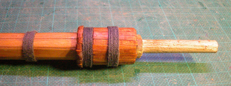
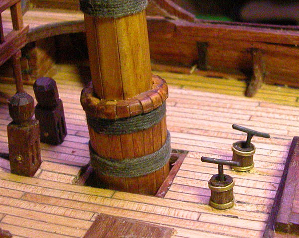
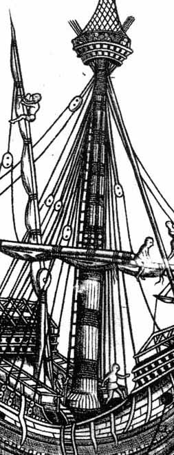
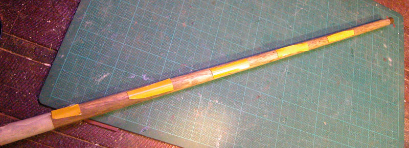
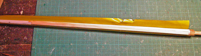
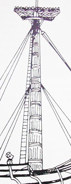
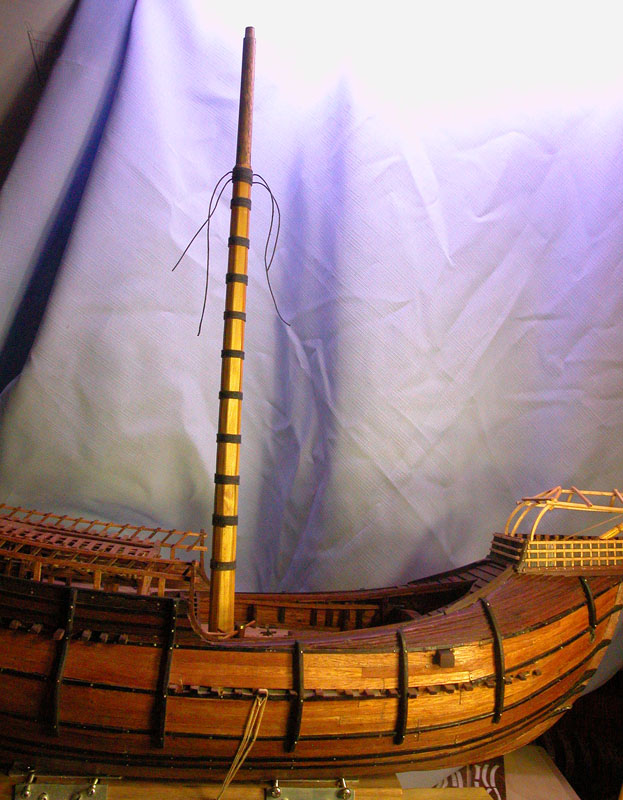
The mainmast. This tapered mast is often undersized in carrack models. Contemporary illustrations show a very substantial mast made even thicker at the base by long wedges inserted vertically into the partners. Although, as discussed previously, the mainmast was usually a built mast with a central spindle and at least eight outer spars, I did not have the carpentry skills to reproduce this in miniature. Therefore I chose to fudge it just a little while maintaining the look and feel of a mediaeval built mast.
Many illustrations show the longitudinal lines along the mast that you would expect if the mast was built and not a single spar.
or
note the wooldings
I started with a tapered spar
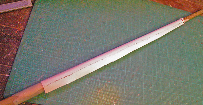
Made a paper template
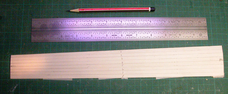
Made strips with the template so that I would end up with eight tapered strips
Glued the strips to pine strips
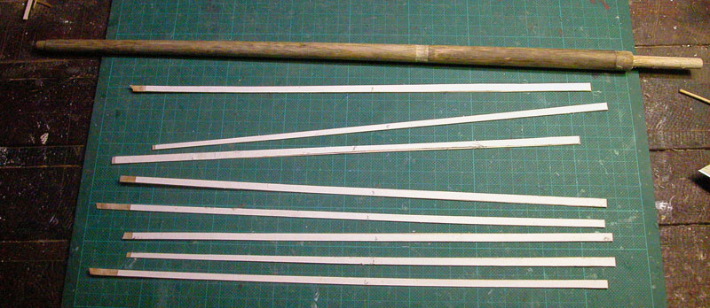
Stuck the pine strips to the mast with double sided tape
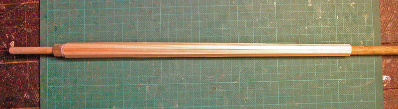
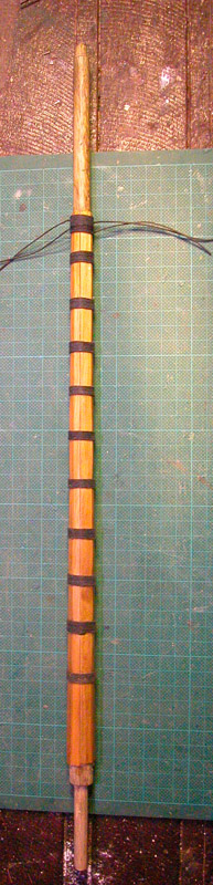
Vessels with built masts had quite a variable number of rope wooldings to reinforce the mast. However they did not use wooden hoops above and below the wooldings as was seen in later periods. It may be that the ropes were reinforced with nails to prevent the ropes slipping.
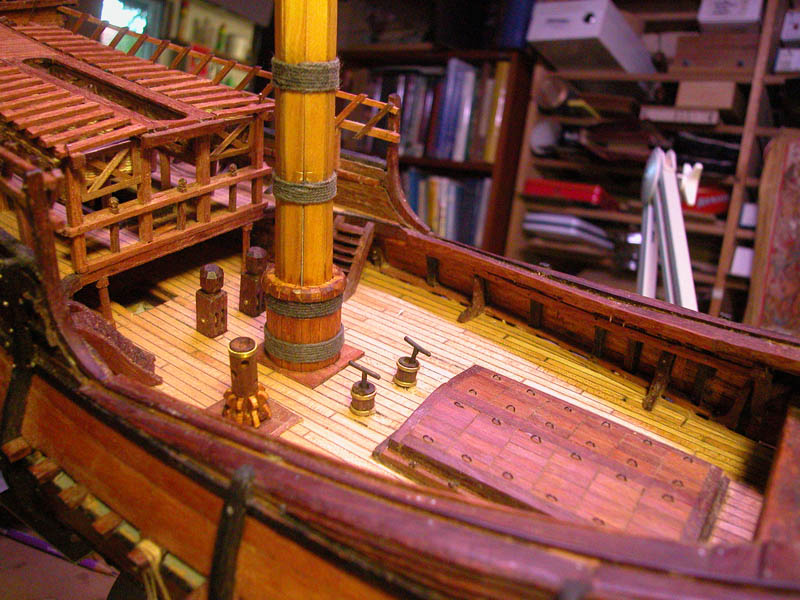
The completed mast
Cheers
Dick
-
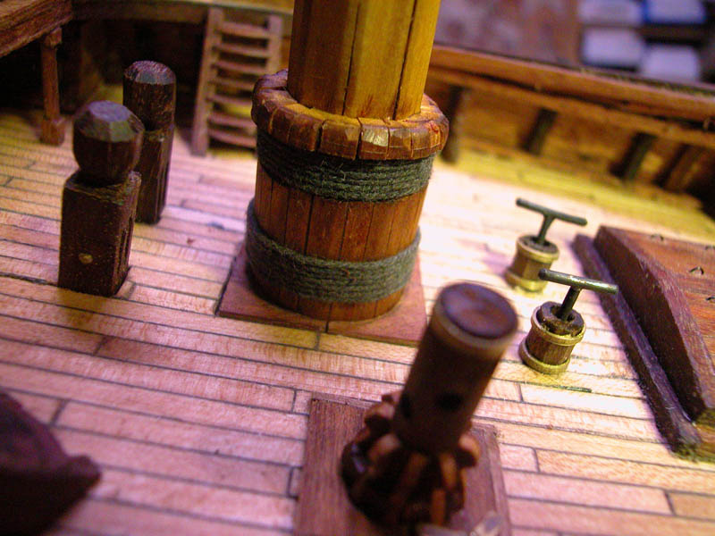
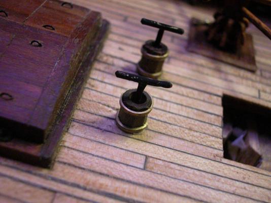
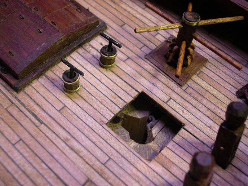
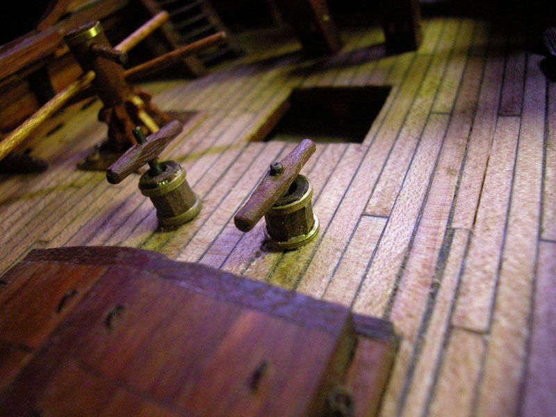
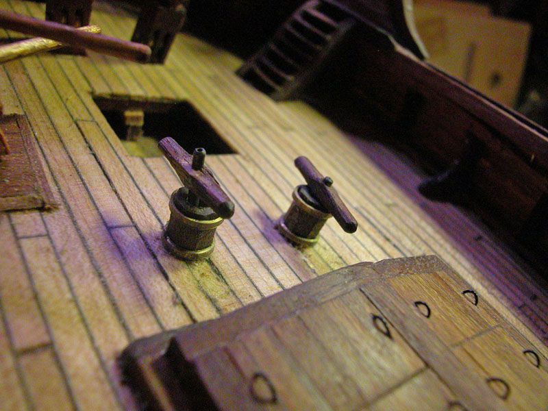
This the pumps with more realistic hand-grips

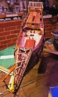 note the asymmetry of the forecastle canopy to allow for the foremast and the bowsprit.
Now to attack the mainmast.
Dick
- cog, seafarermiami, Louie da fly and 10 others
-
13
-
Thanks, Druxey. I will thin them down. Those pumps must have been hell on the back and thighs!!
Dick
- CaptainSteve, dgbot, cog and 5 others
-
8
-
-
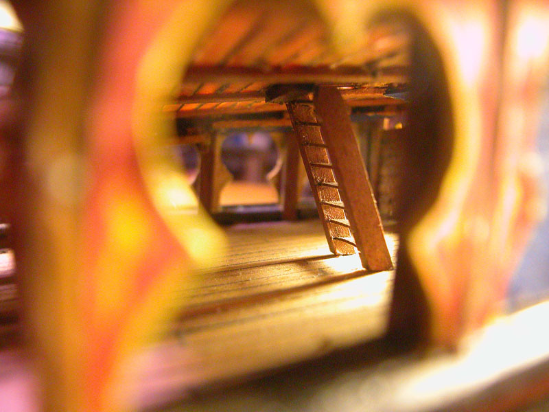
For all my photos I have used an old Nikon Coolpix 5000 digital camera. For these pics I shone a small LED torch through the windows and waited till the autofocus focused the desired bit. It didn't always work. Sometimes I post process with an image processing software but not for these images. I just reduced the image size and cropped.
Dick
-
Inside the Great Cabin with ladder to poop deck

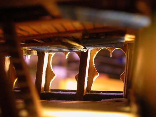
note the blinds in the up position
- Archi, CaptainSteve, druxey and 9 others
-
12
-
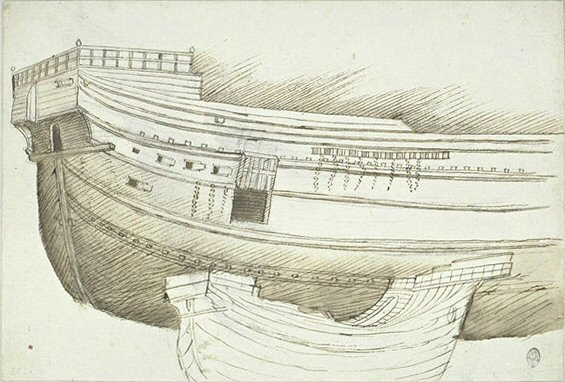
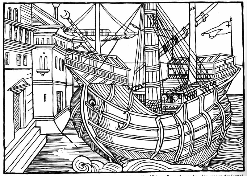
Thanks Steven and Jesse. Yes , I believe Zorzi sketched the vessel while in a slipway or dock. This would explain the incomplete planking on the main wales exposing the frames (see earlier discussion), the lack of masts and the lack of anchors.
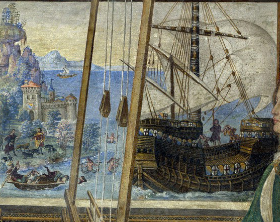
Also I would be loath to deride the ancient illustrators especially those drawing "from life". They are usually correct (vide Carpaccio)
Cheers
Dick
- GLakie, CaptainSteve, cog and 2 others
-
5


Venetian Carrack or Cocha by woodrat - FINISHED - 1/64
in - Subjects built Up to and including 1500 AD
Posted · Edited by woodrat
Blocks on mediaeval ships were somewhat different to those we are used to on later vessels. For example this is my concept of a double block with the pulleys set in-line instead of side-by-side
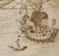
I have installed the backstays first while holding the mast with temporary forestays much as seen in the Trombetta illustration. This sketch I believe was made while the mast was being set up.
Cheers
Dick