HOLIDAY DONATION DRIVE - SUPPORT MSW - DO YOUR PART TO KEEP THIS GREAT FORUM GOING! (Only 13 donations so far - C'mon guys!)
×


AON
-
Posts
2,859 -
Joined
-
Last visited
Content Type
Profiles
Forums
Gallery
Events
Everything posted by AON
-
 They are clearly indicated on the framing drawing... but I will make a note! (there is also one at 2-Aft) Thank you for keeping an eye on me.
 -
.... well there is always "blind luck" I've experienced that many times and "luck of the Irish" ... but I've been blessed with that from birth so GOOD LUCK to you!
-
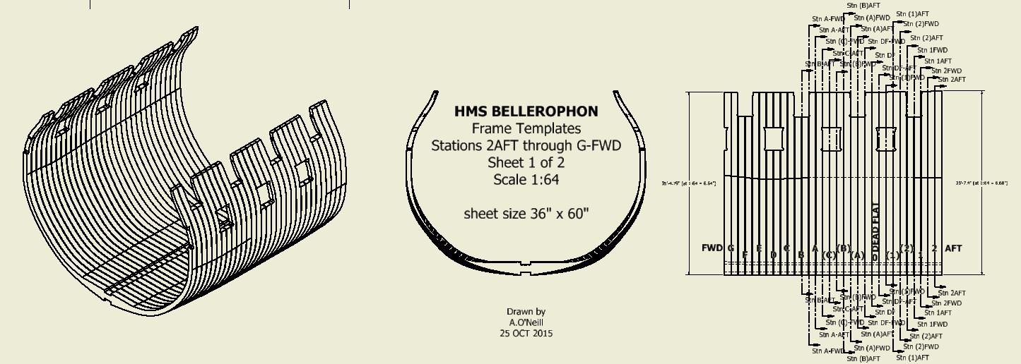
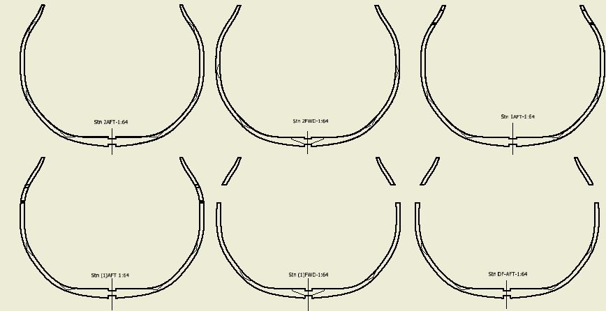
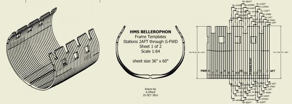
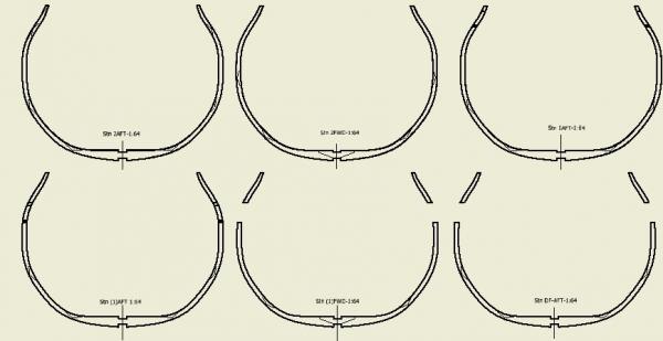
First set done Here are the PDF sheets for the frame templates from 2 to G for your entertainment Moving forward (literally towards the bow ) EDIT NOTE: removed PDF's will post updates/corrections shortly 15 NOV 2015
-
luck has very little to do with it. good things happen mostly by accident
-
here is a sample of the beginning of my frame templates! screen captures are a little grainy when I finish the first set I'll post the PDF
-
the hard part (starting) is done!
-
Don Inventor allows you to project 3D geometry from two 2D views. I didn't see this option in my version of SolidWorks I was borrowing from the office. I was able to project the 3D curvature of the waterline cutting down line, top of the floor timber and top timber lines by drawing them in the Breadth and Sheer views (plans). I then created a end view (Body plan) plane on the station lines and at the locations in which the top timber line changes elevation. I inserted points at the intersection of these lines with the plane, projected these points onto a sketch at the station line (at the plane) and then drew in the frame. I did however come to the conclusion that I needed to simplify the dimensions. (something I believe Druxey was trying to make me aware of) The end of the timber at the top of the rail is 5-1/2" moulded depth (athwartships). at 1:64 this is 0.086" thick or just over 1/16" (about 2mm) I don't think I can make these at this thickness so I increased it to 8" (1/8" or 3mm) Still a challenge but a wee bit better to manage. I also massaged the thickness at the breadth of the beam from 11.8" to 12" I gave up on tweaking all the polylines with setting the 3 handles at every point once I realized there is a traditional autocad polyline option. The task is difficult enough without creating extra challenges. The first, second and third futtock moulded thickness are unchanged... but I believe they will be when I have wood to sand! I'm an old draughtsman (draughtsperson to be politically correct) and it is taking me awhile to adjust and accept what I can and cannot do at 1:64 scale. .... and I am still learning. I am now learning to adjust my thinking of the timber spacing due to the gun port locations. (something else Druxey gentle nudged at) When I project the cuts from below they are straight and play havoc with the templates at the gun ports. I realise the timbers shift. This means cutting from the side (sheer plan) which is tons more work to draw I am not sure the effort is needed so long as I refer to the actual timber plan I have to do the shifts. I've modelled stations 2 through G and started the template drawing for these today. I had planed on cutting all the scarf joints in the timbers but now realising the scale, moulded thickness, my level of talent, who will see it... I'm moving towards simple butt end joints. I may attempt scarf joints where I have break away views through the hull into the interior as you will see these joints. I've also toyed with the idea of plexiglas timbers in these areas. Alan
-
Good morning Don, No, I haven't given up. A number of things occurred to slow me down this summer. First there was the warm inviting sunny days I hadn't seen for months. Then extra work demanding more of my time. Then I caught my finger on my table saw cutting stock to make a honey stick...it is healing and to my surprise the finger nail is growing back! The end of my finger will almost look normal. It has been an uphill battle with creating my templates, now using Autodesk Inventor. My files were huge and going backwards to work on an earlier sketch caused crashes. Then I learnt about dirty files and dumping the temp files to clean up. I've just refined my process and starting over yet again (4th time) but not from the very beginning! This time I honestly believe I will have it. Hope to start reposting again soon. I will also remake my keel and stern post assembly. I know I can do a better job. It is the learning curve that is killing me. Alan
-
Well, it is done and running much better now! step 3 , find the temp folder, was easy step 4, empty the folder was at first impossible as I wasn't allowed access I searched online and discovered others had the same 3D modelling issue and they accessed the temp folder as follows " open windows explorer and type in %temp% " this opened the file and it was full of stuff! then I typed CTRL + A to pick all then I hit the delete key
- 1 reply
-
- 3
-

-
Has anyone ever heard of a "dirty" model or file. My program keeps crashing and I've been told I need to "purge" the file and "delete" the temp files to clear the mess in the memory. The steps I was told to take are: 1. find the file in windows explorer 2. right pick and select purge 3. find the temp file folder in the program folder 4. delete the temp files within the folder 5. reopen my 3D file but DO NOT do anything with it 6. save it immediately 7. close the file 8. close the program 9. re-open the file in the program 10. should be clean and ready to use crash free until it accumulates a new mountain of stuff to clutter the memory. Has anyone done this before? first time for me but all my other (work/job) files are tiny compared to this (ship/model) one.
- 1 reply
-
- 1
-
-
So then 1mm isn't enormously out of scale ,,, only slightly too large. Is the difference that noticeable? If it looks good to you then use what you have If you are a purest then purchased some line a little smaller diameter, closer to scale. For me, knowing now what they should be, I'd have to get the correct line.... even though one in hundreds of people would notice. And since I wouldn't take a caliper to your rigging I would not be the one in hundreds. Alan
-
I think the top mast rigging looks good in the pics (1mm dia x 64) / 25.4 = 2-1/2 inches diameter full size rope 0.75mm = 1-7/8 inch diameter 0.5mm = 1-1/4" dia. what size are they in real life? and what looks good at 1:64 1mm or 2.5" seems too large to me but wait to hear from more seasoned readers! Alan
-
THE 74-GUN SHIP by Jeronimo
AON replied to Jeronimo's topic in - Build logs for subjects built 1751 - 1800
verrrrrry nice indeed! so nice I had to go back twice -
what is the ideal modelling table?
AON replied to AON's topic in Modeling tools and Workshop Equipment
now that is thinking outside the box! -
Having worn navy blue as a sea cadet in the late 60's and early 70's I can attest to there being a slightly noticeable difference between it and black Unfortunately I wore green after that. (The bell bottoms made a great life preserver by the way) For the technical fellows out there.... CMYK value of True Blue Cyan = 84 Magenta = 53 Yellow = 0 Black = 0 CMYK value for Navy Blue Cyan = 100 Magenta = 98 Yellow = 14 Black = 17 CMYK value for Black Cyan = 75 Magenta = 68 Yellow = 67 Black = 90 Of course this has nothing to do with early uniforms and colours which was the original question and so I apologize for that.
-
took me a moment to look away and spot the others hanging off the shelves!
- 968 replies
-
- 3
-
-
- hahn
- oliver cromwell
- (and 1 more)
-
holy sh......ishkabob now I see it if I hadn't seen what you can do I'd say you were crazy this is going to be a treat to watch
- 59 replies
-
- 5
-
-
- norske lowe
- billing boats
- (and 1 more)
-
This is the response I rec'd this morning from our local SW rep. I was able to confirm that this program is in effect.... (snipped) ... you can purchase the license online. Support is provided as well.... (snipped) any files created with this edition are watermarked. The link is https://store.solidworks.com/veteran/default.php price is $20 (I am assuming it is US$) at this site it states SW 2015/16 does not work with Windows XP (this may be a problem for me) Looking at the application form (DND 2381) for the NDI 75 card you must have 10 or more years service in any component of the Canadian Armed Forces to qualify. You require 2 colour passport type photos and payment of a $15 processing fee.
-
Terry I need to check in here more often I just sent a note to our SW provider to ask if this is true because last time I spoke to him he said there were absolutely no special deals for anyone. If this is true I can hopefully get a card for $15 (or maybe send them a copy of some paperwork) Alan
-
Of all the challenges this ship will toss your way I just can't seem to see past the dust! I'd say good luck but you're in a group that doesn't need it! So happy refit! Alan
- 59 replies
-
- 4
-
-
- norske lowe
- billing boats
- (and 1 more)
-
You made me laugh not once but twice! We all would steal AEW's whole library and I love the shot (pun intended) with the level!! I appreciate the large photos (and not just because I'm old). I just discovered a few weeks ago that if I use the roller on my mouse with the CTRL button held down I can zoom in on the photos so the large photos plus the zoom works really well for me Keep up the fantastic build as this guy literally half way round the world will be learning from you.
-
My New Found Respect for Table Saws
AON replied to AON's topic in Modeling tools and Workshop Equipment
I've spent the week watching table saw videos on line and it is amazing what some people creating these instructional videos do. Of course I'd not have given it a second thought before last Sunday. I've decided I do not like the back corner edge push stick as much as I thought and those pads still put your hand too close for my taste. I'll be creating a hybrid push pad/stick to assure my hand is well back and I'll be making myself a RIPPING JIG ( ). The scariest TABLE SAW video describing kick back was found here ( ) This guy has prooven the push pad with a low over the top grip is a bad thing. Once again I did not experience kick back, my accident was due to the weakness in the wood due to the hole allowing it to bind and twist from the outside. My table saw guards, riving knife and toothed anti kick back attachment did absolutely nothing for me.