cdrusn89 Posted January 9, 2023 Author Share #181 Posted January 9, 2023 The rail on top of the q-gallery roof was not as hard as expected although I did manage to lose three of the posts somewhere on the floor when they "popped" out of my tweezers. I am going to try the frieze next - am considering doing all the friezes on the starboard side before shifting attention to port side but jury is still out. It would sure be nice to have one side "done" (more or less). Edwardkenway, FrankWouts and scrubbyj427 3 Thanks, Gary Current Build - HMS Sphinx 1775 Prior Builds: HMS Winchelsea USF Confederacy Link to comment Share on other sites More sharing options...
cdrusn89 Posted January 9, 2023 Author Share #182 Posted January 9, 2023 (edited) And now with the top rail on the top rail. I left the ends of the top rail "loose" so when the time comes I can get them up to the transom and side - it may take a little "surgery" on the top to get it "right" but I think I have enough "play" to accommodate. Edited January 9, 2023 by cdrusn89 dvm27, FrankWouts, bdgiantman2 and 1 other 4 Thanks, Gary Current Build - HMS Sphinx 1775 Prior Builds: HMS Winchelsea USF Confederacy Link to comment Share on other sites More sharing options...
cdrusn89 Posted January 9, 2023 Author Share #183 Posted January 9, 2023 (edited) I "solved" the molding cutter not having the correct size (3mm vs. 3/32) by cutting the molding at 3mm then using the thickness sander to thin it down in both dimensions so I end up with 3/32" X 1/32". That was reasonably straightforward, at least when you have all the necessary machinery. So the end point of the "middle" molding at the stern is the molding on top of the q-gallery windows. At the waist I am confused. Currently there is nothing on top of the hull planking at the waist - it looks like this: So is the scraped molding supposed to be flush with the top of the waist as it exits now or some amount higher to accommodate something that finishes off the tops of the bulkhead extensions later? Or have I missed something entirely? That however is not the only issue I have found. I have a gap of about 5/32" between the top of the frieze and the top of the bulwark just forward of the q-gallery. It narrows down to the thickness of the bulwark cap (1/16 - 3/64) between gun ports 11 and 12. For this picture the center molding is flush with the top of the bulwark at the waist as shown below I am going to start researching the other build logs to see if I can figure out where the middle fancy molding is supposed to be at the waist. Until that is established I will work the port side q-gallery. Okay - problem, at least where the middle fancy molding goes at the waist problem solved. Chuck's build log (page 22 about 3/4 the way down) shows pictures of the model with the friezes and fancy molding installed and you can see the tops of the bulkhead extensions at the waist. So the middle fancy molding is flush with the top of the bulwark at the waist. Edited January 9, 2023 by cdrusn89 Edwardkenway and FrankWouts 2 Thanks, Gary Current Build - HMS Sphinx 1775 Prior Builds: HMS Winchelsea USF Confederacy Link to comment Share on other sites More sharing options...
cdrusn89 Posted January 10, 2023 Author Share #184 Posted January 10, 2023 Added the friezes, the "thing" under the q-gallery, the "fancy" molding at the top of the bulwark, and the molding above the "thing". Roof, fancy molding and statue are still just sitting there. Working on the rest of the friezes and the molding. Going better than I had anticipated. I added a small triangular piece of frieze to cover the gap between the frieze and the top of the bulwarks. I think it will be essentially invisible with the fancy molding in place Chuck, FrankWouts, scrubbyj427 and 3 others 6 Thanks, Gary Current Build - HMS Sphinx 1775 Prior Builds: HMS Winchelsea USF Confederacy Link to comment Share on other sites More sharing options...
cdrusn89 Posted January 10, 2023 Author Share #185 Posted January 10, 2023 Starboard side from stern to waist is "finished". I looked all over the plans and could not find a description of the molding that I am supposed to scrape so I "faked it". The middle one is "two grooves (aka three humps)" and the lower is one groove - just so they are different. Working the forward portion now - may get it finished tomorrow so I can switch to the port side. Need to mill more molding too. And there are 22 more cannon to mount on the carriages. Edwardkenway, Oldsalt1950, Rustyj and 2 others 5 Thanks, Gary Current Build - HMS Sphinx 1775 Prior Builds: HMS Winchelsea USF Confederacy Link to comment Share on other sites More sharing options...
cdrusn89 Posted January 11, 2023 Author Share #186 Posted January 11, 2023 Starboard side forward of waist completed. On to the port side! JpR62, Edwardkenway, Ryland Craze and 4 others 7 Thanks, Gary Current Build - HMS Sphinx 1775 Prior Builds: HMS Winchelsea USF Confederacy Link to comment Share on other sites More sharing options...
cdrusn89 Posted January 11, 2023 Author Share #187 Posted January 11, 2023 Starboard side - I put one coat of Wipe-on-Poly over the entire side (above the wales; wales have 4 coats already). I am finding it hard to get started on the port side as it seems the gremlins have made off with some of the parts (q-gallery uprights for instance). Perhaps a pause to clean up and put things back where they belong is in order. scrubbyj427, JpR62, dvm27 and 4 others 7 Thanks, Gary Current Build - HMS Sphinx 1775 Prior Builds: HMS Winchelsea USF Confederacy Link to comment Share on other sites More sharing options...
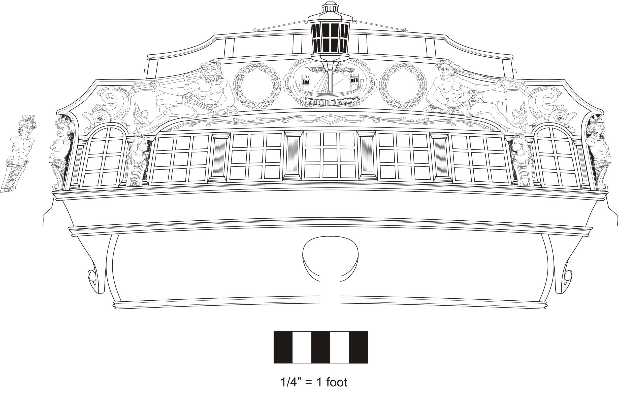
cdrusn89 Posted January 17, 2023 Author Share #188 Posted January 17, 2023 Somehow I must have missed the directions to add the friezes to the transom area so I took the time now to invert the hull and add them as well as the molding that outlines the upper and lower counter. I also painted the upper transom area the cerulean blue using the Window Newton watercolor paint. As suggested I used the blue plus a drop of white. I think it is pretty close to the blue in the friezes but could probably have used another drop of white. I have a few more touch-ups to do on the port side and then it is more transom detailing including adding the stern "decorations". Matt D, James G, Chuck and 6 others 9 Thanks, Gary Current Build - HMS Sphinx 1775 Prior Builds: HMS Winchelsea USF Confederacy Link to comment Share on other sites More sharing options...
Chuck Posted January 17, 2023 Share #189 Posted January 17, 2023 Very nice....moving right along. cdrusn89 and FrankWouts 2 Chuck Passaro - MSW Admin Sloop Speedwell - POF scratch Block Island Boat - POF scratch HMS Winchelsea - POB scratch build HM Cutter Cheerful - POB scratch build Royal Barge - POF scratch Medway Longboat- POF Scratch SYREN SHIP MODEL COMPANY Link to comment Share on other sites More sharing options...
glbarlow Posted January 17, 2023 Share #190 Posted January 17, 2023 There is another moulding at the bottom of the counter where the frieze meets the planking you could add. FrankWouts and cdrusn89 2 Regards, Glenn Current Build: HMS Winchelsea Completed Builds: HM Flirt (paused) HM Cutter Cheerful, Lady Nelson, Amati HMS Vanguard, HMS Pegasus, Fair American, HM Granado, HM Pickle, AVS, Pride of Baltimore, Bluenose Link to comment Share on other sites More sharing options...
cdrusn89 Posted January 18, 2023 Author Share #191 Posted January 18, 2023 Thanks Chuck and Glenn - yes; I did not notice the lower counter molding until you mentioned it. Has been added using the same molding as below the friezes on the sides. And since I have the hull upside down decided now would be a good time to drill out the hole for the rudder. But, I need to assemble the rudder to make sure I make the hole big enough. So, since I have the chapter 5 wood package I got out the rudder and the accessories (pintles and gudgeons) and put the rudder together. Here is the rudder and the hole. I decided to only make the hole as large as necessary. I will touch up the edges of the hole and frieze before turning the hull over again. I will not actually install the rudder now, just get everything ready so it will just "slip in" when I get to chapter five. Oldsalt1950, FrankWouts, James G and 4 others 7 Thanks, Gary Current Build - HMS Sphinx 1775 Prior Builds: HMS Winchelsea USF Confederacy Link to comment Share on other sites More sharing options...
cdrusn89 Posted January 18, 2023 Author Share #192 Posted January 18, 2023 While waiting for things to dry, or to take a break from whatever is bedeviling me at the moment I took a crack at the cove molding. I tried for the "concave look" as described in the monograph but am not sure I was successful. I used the same red color (Badger Windjammer Red) as I used on the gun carriages and will use on the interior bulwarks so it does not look quite like the monograph. One word for those who may come later to Winnie - the transom and thus the cove molding is curved in the fore/aft dimension. Make sure the molding inside the cove is well secured before trying to attach it to the transom. Luckily I discovered this "issue"during a dry fit and was able to correct it on the workbench. Would have been a bit more of a challenge if the cove was glued to the transom and interior molding popped off. Matt D, Edwardkenway, JpR62 and 5 others 8 Thanks, Gary Current Build - HMS Sphinx 1775 Prior Builds: HMS Winchelsea USF Confederacy Link to comment Share on other sites More sharing options...
cdrusn89 Posted January 19, 2023 Author Share #193 Posted January 19, 2023 Working on the rudder mounting - I took Chuck's advice in the monograph and only put pins in the lowest and next to the uppermost hinge points. The very top one is almost inside the opening so that one would be hard to maneuver. So here are the two hinges with their supports attached to the hull. I will add the interior hinges (no pins) after I get the corresponding hinges on the other side in place. I used 24 gauge wire in the holes at the ends of each piece and fishing line elsewhere. A drop of thin CA on each wire/line was all I used to secure the pieces to the hull. Hopefully no one is going to try and "swing the rudder". Chuck, Gregory, FrankWouts and 5 others 8 Thanks, Gary Current Build - HMS Sphinx 1775 Prior Builds: HMS Winchelsea USF Confederacy Link to comment Share on other sites More sharing options...
cdrusn89 Posted January 20, 2023 Author Share #194 Posted January 20, 2023 I decided to fit the rudder now that I have it "complete". I still need to touch up some of the black on the pintles and gudgeons but hopefully that will not mess things up too much. With the hull back upright I dry fit the cove and the items above it. I had to take a bit off the edges of the center molding in order for it fit between the wreaths. I will add the stern windows after I get all the decorations on the stern completed to avoid the possibility of poking one out or otherwise damaging them during the decoration installation. scrubbyj427, JpR62, Rustyj and 6 others 7 2 Thanks, Gary Current Build - HMS Sphinx 1775 Prior Builds: HMS Winchelsea USF Confederacy Link to comment Share on other sites More sharing options...
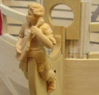
cdrusn89 Posted January 29, 2023 Author Share #195 Posted January 29, 2023 (edited) Adding the ornamentation to the stern. Got the port side "finished" (touch up needed). I am not sure why the "wreaths" have a different "color" than the rest of the ornaments. They are supposedly all CDC machined boxwood but... For what it is worth the figures aft of the q-gallery windows are also the same color as the wreaths. Everything is going to get another coat of matte finish once the touch-up is done but I may have to live with the color difference. At least it is consistent on each side - so far. I would echo the monographs caution about the figures being delicate. I broke the leg off the figure while filing the grove in the bottom to allow them to extend over the cove. Not the best job "fixing" it but it is hopefully not too noticeable without the close up photo. Edited January 29, 2023 by cdrusn89 Gregory, Vladimir_Wairoa, Edwardkenway and 2 others 4 1 Thanks, Gary Current Build - HMS Sphinx 1775 Prior Builds: HMS Winchelsea USF Confederacy Link to comment Share on other sites More sharing options...
jfhealey Posted January 29, 2023 Share #196 Posted January 29, 2023 This is looking lovely. Beware the rudder however. The boxwood hinges from Syren ( I assume that is what you used) are very fragile and the rudder easily knocked. I broke mine though Chuck very kindly sent me another set. I suspect the colour difference in the boxwood wreaths will settle down and in time you won't notice it. All the best Fred FrankWouts and cdrusn89 2 Link to comment Share on other sites More sharing options...
glbarlow Posted January 30, 2023 Share #197 Posted January 30, 2023 Did you add sanding sealer to the boxwood decorations? That helps even out the color. cdrusn89 and FrankWouts 2 Regards, Glenn Current Build: HMS Winchelsea Completed Builds: HM Flirt (paused) HM Cutter Cheerful, Lady Nelson, Amati HMS Vanguard, HMS Pegasus, Fair American, HM Granado, HM Pickle, AVS, Pride of Baltimore, Bluenose Link to comment Share on other sites More sharing options...
cdrusn89 Posted February 3, 2023 Author Share #198 Posted February 3, 2023 Thanks for the tip on the sanding sealer. Not sure I am at a point where I can use it now but when I get to the figurehead I will definitely give it a try. Anyway, I managed to get all the stern decoration installed and an additional coat of flat finish applied. I did not use the kit provided "columns". But I did use the residual pieces from the kit provided upper molding (laser cut) to fill in above and below the "columns" which I made from boxwood using the same molding cutter I used for the middle side molding although I used it at its full 3mm width instead of the 2.4mm width used on the sides. Unless I have missed something (highly likely) this concludes the stern decorations. I still have to add the window frames but am not going to add them until I actually have to - I fear they are too fragile and I am too clumsy to avoid damage until there is no way to avoid it. scrubbyj427, James G, FrankWouts and 4 others 7 Thanks, Gary Current Build - HMS Sphinx 1775 Prior Builds: HMS Winchelsea USF Confederacy Link to comment Share on other sites More sharing options...
cdrusn89 Posted February 4, 2023 Author Share #199 Posted February 4, 2023 With the stern completed (finally!!) focus shifts to the interior. First step is to plank the two interior platforms below the gun deck. In the forward platform I must have gotten the centerline plank a bit off to one side because when I got to the outboard edges I had to use a 3/16" wide plank on one side and a 7/32" on the other.Not that anyone is going to see much of the platforms anyway but... So here is the forward platform with the supports glued in and the decking sanded and tack ragged but not yet WoPed. Before I glued the supports in I checked to make sure they were square with the bulkheads - no issues. So I planked the aft platform and was adding the supports. When I checked for square I found a slight slant with the aft end being inboard slightly. I clamped a square to bulkhead 21 and am in the process of gluing in the starboard support member perpendicular to bulkhead 21. I am tempted to use some thin CA to secure the support as it has taken me more than a few tries at getting the support square and level with the four bulkheads it touches. A problem for this weekend since no football. JpR62, FrankWouts and Edwardkenway 3 Thanks, Gary Current Build - HMS Sphinx 1775 Prior Builds: HMS Winchelsea USF Confederacy Link to comment Share on other sites More sharing options...
FrankWouts Posted February 4, 2023 Share #200 Posted February 4, 2023 You're making great progress and looking gooed Gary! Keep up the good work, I'll stay tuned! Frank. cdrusn89 1 Current builds on MSW: HMS Winchelsea 1:48: Prior builds on MSW: None Link to comment Share on other sites More sharing options...
cdrusn89 Posted February 4, 2023 Author Share #201 Posted February 4, 2023 Thanks Frank - I looked at your blog this morning. You have the planking "down". I wish I could do as well. I think I got the carlings for the aft companionway cut so they just "drop" into the mortises - no distortion of the center beam, which would be easy to do - don't ask me how I know, please. With those in place I moved on to adding the false deck. I had to take a bit off the outer edge of all of the false deck pieces but got them all dry fitted and lined up before I when to the glue (neutral pH PVA). I found a use for the machinists angles that I have accumulated over the years. Are excellent weights to keep the false deck pressed down on the underlying structure. I had enough to do three sections at a time. When the aft deck was dry (overnight) I couldn't resist placing one of the guns and a 1/48th figure that I got through the NRG Store "on deck". Gregory, FrankWouts and Edwardkenway 2 1 Thanks, Gary Current Build - HMS Sphinx 1775 Prior Builds: HMS Winchelsea USF Confederacy Link to comment Share on other sites More sharing options...
cdrusn89 Posted February 4, 2023 Author Share #202 Posted February 4, 2023 With the false deck in place the next step is to add the fillers on either side of the bow. It appears that I had already considered this area as requiring extra support since I apparently added an intermediate support between bulkhead W and the bow (on each side). I seem to remember having a difficult time keeping everything "together" while framing in the forward gun ports. Anyway, I added the bow filler below the lower sill but had to add the filler in two pieces above the lower sill. Fairing comes next, before adding the strip below the bowsprit hole is added. While waiting for the glue to dry on the fillers I added the inner sheave shells for the forward two sheaves (aft one is to wait until the first layer of bulkhead planking (per instructions). Edwardkenway, Gregory and FrankWouts 3 Thanks, Gary Current Build - HMS Sphinx 1775 Prior Builds: HMS Winchelsea USF Confederacy Link to comment Share on other sites More sharing options...
cdrusn89 Posted February 5, 2023 Author Share #203 Posted February 5, 2023 (edited) The next step is to add the first two rows of bulkhead planking. The upper row should be level with the bottom up the gun ports. The upper piece is 7/32" wide and to lower one is whatever width nit takes to get the upper strake even with the gun port bottom. The instructions note that there may have to be adjustments to keep the upper strake where it needs to be. I decided that maybe it would be easier (on me) to run the upper strake first. adjusting its "run" to stay level with the gun port bottoms. That way I could guarantee the upper strake is level and make whatever adjustments are required to the bottom strake. So here is the aft starboard side with the upper strake glued in place. The piece on deck will be the bottom strake. It is 1/8" wide. Clearly I have less distance between the deck and the gun ports since Chuck's model used a 1/4" wide strake on the bottom. I am not sure what impact this will have going forward. All I can do now is hope the port side is the same. Meanwhile here is the bow, faired with the filler and centerline pieces added. I also added a small piece at the bow to bridge across the gap between the hull and the stem. It cleans up that surface but may interfere with some of the bow work yet to come so I only glued it to the hull to reduce problems if forward portion has to be removed later. It will all be painted black in the end. Edited February 5, 2023 by cdrusn89 Matt D, scrubbyj427, James G and 2 others 5 Thanks, Gary Current Build - HMS Sphinx 1775 Prior Builds: HMS Winchelsea USF Confederacy Link to comment Share on other sites More sharing options...
cdrusn89 Posted February 5, 2023 Author Share #204 Posted February 5, 2023 A bit of housekeeping. I learned (the hard way) when building Confederacy that things seem to have a sixth sense when it comes to open hatchways. To keep foreign objects from finding their way into the hatchways I covered them with masking tape. I plan to cut thin basswood sheet to fix inside the coamings until the gratings are available and will keep them fitted to the companionways until the model is essentially finished. Having snagged my sleeve on the stern frame extensions once while working the interior planking behind the q-gallery entrance (no damage thankfully) I decided to add some protection there as well. Two pieces of thin sheet wood held in place with 1.5" binder clips. FrankWouts, Matt D, scrubbyj427 and 2 others 5 Thanks, Gary Current Build - HMS Sphinx 1775 Prior Builds: HMS Winchelsea USF Confederacy Link to comment Share on other sites More sharing options...
Edwardkenway Posted February 5, 2023 Share #205 Posted February 5, 2023 I shall borrow then stern cover idea if you don't mind! Your Winnie is looking good! cdrusn89 and FrankWouts 2 Current builds; Henry Ramey Upcher 1:25 Providence whaleboat- 1:25 HMS Winchelsea 1764 1:48 Completed: HM Cutter Sherbourne- 1:64- finished Triton cross section scratch- 1:60 - finished Non ship: SBD-3 Dauntless 1:48 Hasegawa -FINISHED Link to comment Share on other sites More sharing options...
cdrusn89 Posted February 5, 2023 Author Share #206 Posted February 5, 2023 (edited) Thanks. Use it with my complements Edward - better safe than sorry; especially after all the work on the stern. I decided that I am going to put two rows of 1/4" wide planks between each gun port and then put whatever size/configuration is required to get a row that is even across the top of the gun ports. I have plenty of 1/4" planks but am running low on 7/32" and 3/16" for some reason (waste/mistakes perhaps). Here is the q-gallery entrance on the starboard side with 2 rows of 1/4" planking. I am waiting for the rows over the gun ports to establish the width/configuration of what goes above these two. Here are the first five gun ports with two 1/4" planks - take my word for it. Did I mention you can never have too many clamps? Edited February 6, 2023 by cdrusn89 FrankWouts, Rustyj and Edwardkenway 3 Thanks, Gary Current Build - HMS Sphinx 1775 Prior Builds: HMS Winchelsea USF Confederacy Link to comment Share on other sites More sharing options...
cdrusn89 Posted February 8, 2023 Author Share #207 Posted February 8, 2023 Starboard side interior planking ready for deck clamp installation. Except for the after most piece behind the q-gallery door. Since it is important (according to the instructions) that the bottom of the deck clamp slot at the transom not be above the top of the stern windows I am going to make sure that is the case and then fit whatever piece is necessary to fill in the space between the lower plank and the bottom of the deck clamp. FrankWouts, scrubbyj427, Edwardkenway and 1 other 4 Thanks, Gary Current Build - HMS Sphinx 1775 Prior Builds: HMS Winchelsea USF Confederacy Link to comment Share on other sites More sharing options...
cdrusn89 Posted February 9, 2023 Author Share #208 Posted February 9, 2023 While waiting for glue to dry I inventoried the paneling for the cabins. Good thing as I noticed that the forward panel for the starboard side had both come adrift from the carrier but also broke off the upper most part of the panel. I think it will likely not be noticable but that will be the last panel installed "just in case" a new one is needed. Her are the pieces, starboard side on the right with tape holding the two pieces together. I have since stored them in separate containers so I don't have to divide them up again. Edwardkenway, westwood and FrankWouts 3 Thanks, Gary Current Build - HMS Sphinx 1775 Prior Builds: HMS Winchelsea USF Confederacy Link to comment Share on other sites More sharing options...
cdrusn89 Posted February 9, 2023 Author Share #209 Posted February 9, 2023 (edited) I got the first layer of interior planking completed in the quarterdeck area and decided to see how the deck clamps/beams were "shaping up". Assuming I got the false deck pieces installed on the centerline (hopefully I did not screw that up) I thought it might be useful to see how the deck beams would fall. Hopefully perpendicular to the centerline although that might be hard to demonstrate since I have not found a way to get the centerline accurately extended up to the plane where the q-deck beams are. I clamped the deck clamps in place at the hance pieces and tried to line the notches for the last deck beam (on this section of the deck clamp) with a nearby bulkhead extension. Then I got a deck beam (cherry in this case), trimmed it to fit, being careful to take equal (more or less) amounts off each end and fit that into the slot for the after most beam. Then I took two squares, set them on the false deck on the outer most etched lines running fore/aft and looked for how far the squares were from the etched line running athwartships (which is where the forward cabin bulkhead will go). Then I adjusted one of the deck clamps (the starboard one) to get the two squares equidistant from the athwartship line. Here is how that looks: I know they do not look like they are equidistant but I think that is due to the camera's point of view. Looking at it in "real life" they are as close to equidistant as I can get them, even with my "auxiliary eyes" on. I then moved the beam to a forward deck clamp notch that is near the junction between the after two false deck sections. I wanted to check that I had not just picked an auspicious place to run the first check. Here is the picture of the forward "check point". Pretty darn close Since I started with the two deck clamps aligned on one of the bulkhead extensions I wanted to see how much I had moved them "out of alignment" so here are where the two deck clamps are now. This is the port side which was not moved - notch is just aft of the bulkhead extension. This is the starboard side which shows the deck clamp is about 1 mm forward of the aft side of the bulkhead extension. I am going to add the after section of the deck clamps and see how thing look at the stern before taking any drastic action - like gluing the deck clamps in place. Edited February 9, 2023 by cdrusn89 Tom E, Edwardkenway and FrankWouts 3 Thanks, Gary Current Build - HMS Sphinx 1775 Prior Builds: HMS Winchelsea USF Confederacy Link to comment Share on other sites More sharing options...
cdrusn89 Posted February 9, 2023 Author Share #210 Posted February 9, 2023 I installed (clamped) the after portion of the deck clamp on both sides following the instructions and not "tampering with" the junction between the two sections. Here is what it looks like at the stern on each side: Starboard side Port side Looks like they are just short of the transom and, as required, the bottom of the notch is just below top of the stern window opening. I put a 3/64" thick piece of scrap between the transom and the deck clamp on each side to get a better view of how much space between the transom and deck clamp. Here is what that showed: Looks pretty close on each side. I put a deck beam in the aft most slot to see how that would look. I think it is time to glue these deck clamps in place. FrankWouts, Vladimir_Wairoa, James G and 3 others 6 Thanks, Gary Current Build - HMS Sphinx 1775 Prior Builds: HMS Winchelsea USF Confederacy Link to comment Share on other sites More sharing options...


Recommended Posts