


thibaultron
-
Posts
2,876 -
Joined
-
Last visited
Content Type
Profiles
Forums
Gallery
Events
Posts posted by thibaultron
-
-
-
Though written for metal casting, the following book will give you ideas on how to make molds for complex parts. Just use RTV rather than sand.
http://www.hnsa.org/resources/manuals-documents/single-topic/foundry-manual/
The ultimate graduation test was making a saucer, and tea cup, with a spoon sitting in the cup as all a one piece casting, not assembled as separate parts.
-
-
-
-
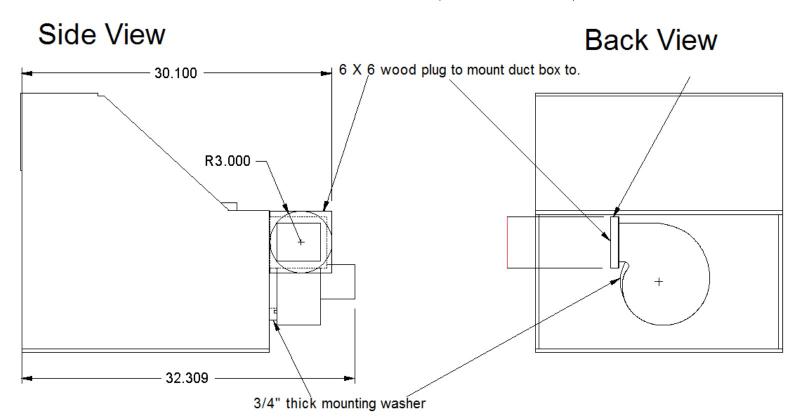
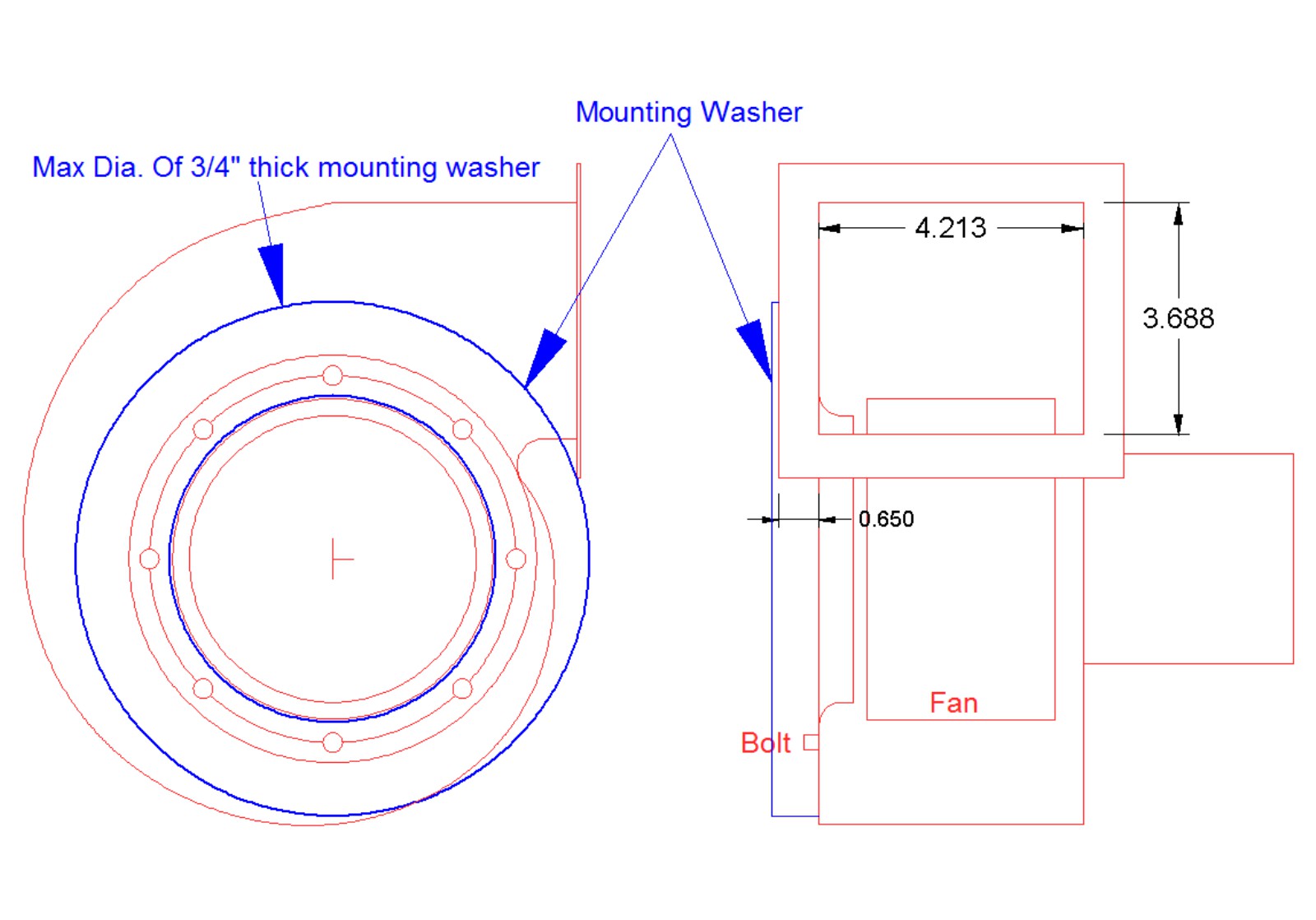
I found a manufacturer spec. sheet for the blower I bought, and have determined my initial design for mounting and venting it. Here is the drawing I made from it.
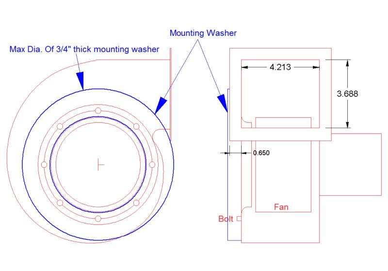
The blue washer I’ll explain later.
The inlet diameter of the blower is ~4.8”. I didn’t want to just have the mounting bolts sitting directly on the blower wall wood, I’d like to have a metal ring, to spread the weight, and keep the bolt heads from working down through the wood.
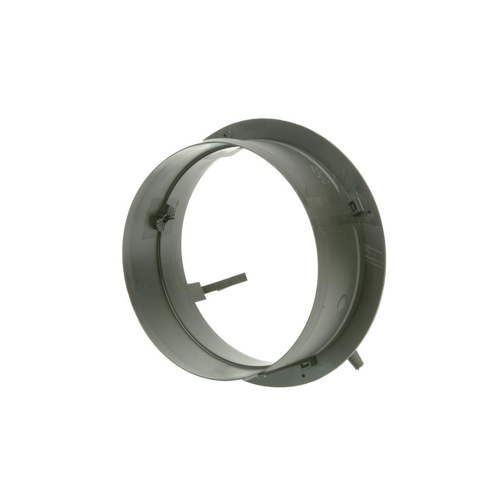
There is an inlet ring that has a funnel shape that comes down close to the blades. My initial thought was to simply use this inside the booth as the metal support, but then I realized that this makes a seal to prevent backflow.
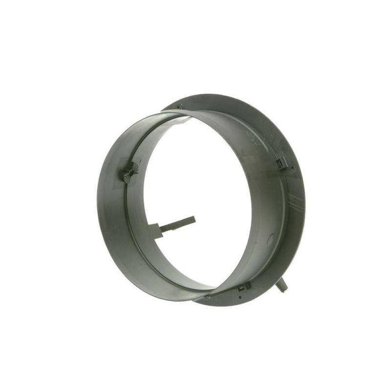
Looking on the net, I found a 5” duct bulkhead like fitting. So I plan on having the flange of this as the metal support ring. I’ll trim the duct portion to fit so that it stops just short of the inlet ring.
Have been watching a video series where the guy did use the inlet ring inside the booth, and he had major blowback problems.
For the outlet plumbing, I’m going to use 6” duct. The blower outlet is about 3 1/4” X 4 1/4”, so this should give me a low restriction flow.
I’m not sure which of the two ways below, I’m going to use to adapt the outlet to the duct.
- Fashion a round wood plug that bolts to the outlet. The duct will fit over, that then be secured with screws.
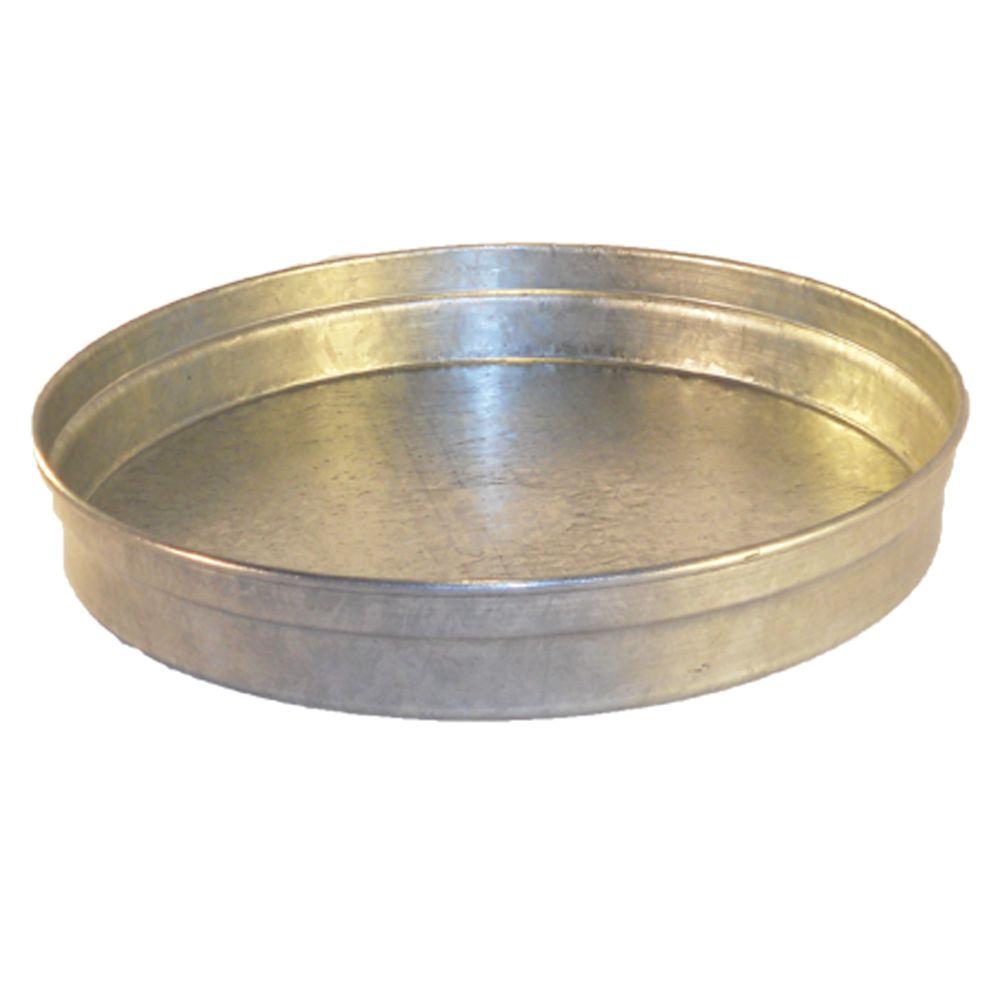
- Use a metal end cap, and cut out the center to match the outlet.
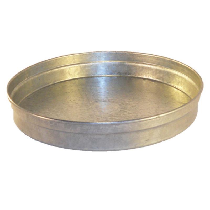
I was leaning toward the wood plug, but the cap would be stronger, and not much, if any, more effort to make.
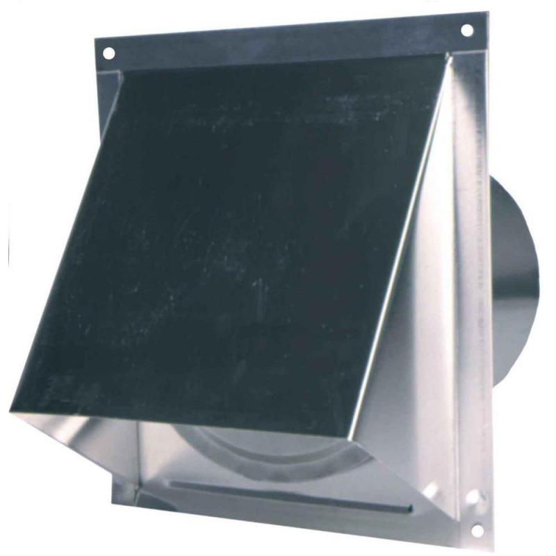
I also found a 6” duct wall vent. Like a drier vent on steroids.
Back to the blower mount. The blower can’t just be bolted directly to the booth wall. The outlet flange would hit the wall. So it has to be held away from the wall. I plan to use a ¾” wooden flat donut, for the spacer. This will get the outlet flange just clear of the booth wall, and provide a good seal between them.
So the mount will consist of: The 5” bulkhead mount,(trimmed), the wall, the donut, and the inlet ring, where it is supposed to go. I was thinking of using all 8 of the available inlet ring screw holes, but just the four actually used by the manuf., should be enough. The other four are provided so that the blower can be rotated 45 deg., if needed from the holes in whatever equipment it attached to.
Here is a drawing of the blower mounted to the booth.
When the blower actually gets here, I’ll double check the measurements.
- GemmaJF, mtaylor, Bill Tuttle and 1 other
-
 4
4
-
Kurt;
Your right 3/8" should work, it doesn't have to carry more than it's own weight.
I see what air flow I get with the blower. It should be here by the end of the week.
I've figured out how to mount, and plumb it. I'm planning on using 6" duct work, for the output end. Metal not flex hose. It will only have to run about 6' when in it's final place.
-
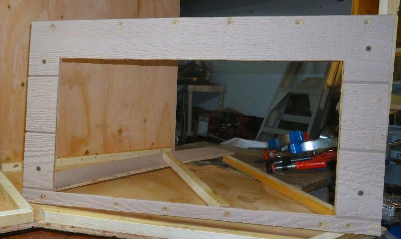
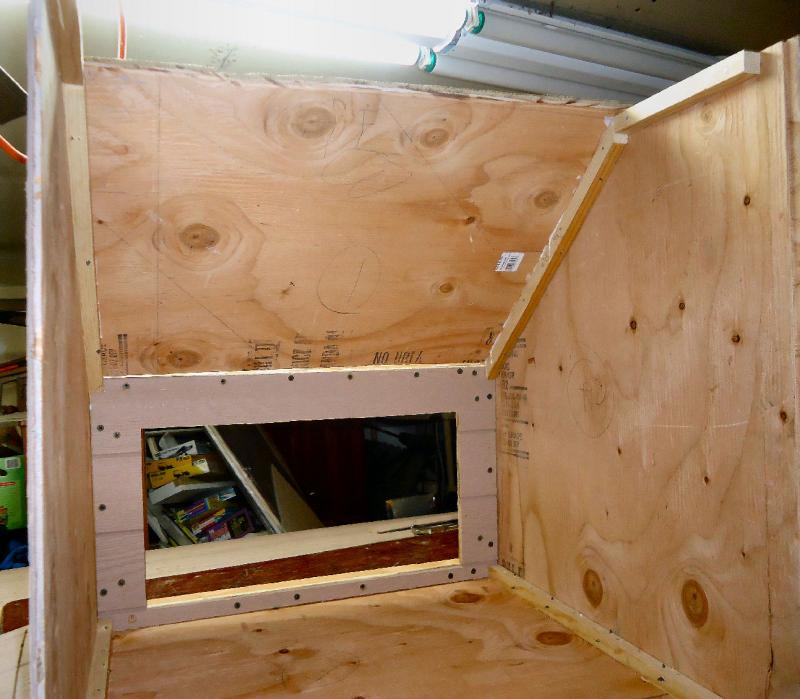
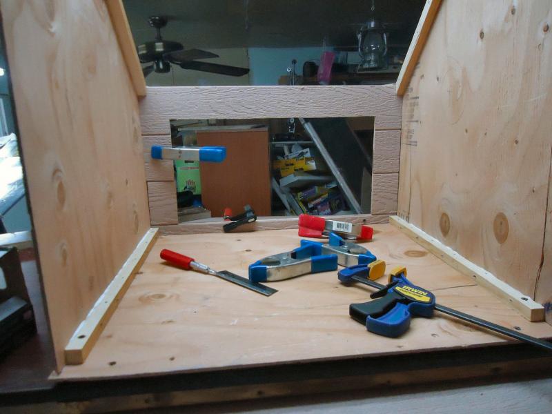
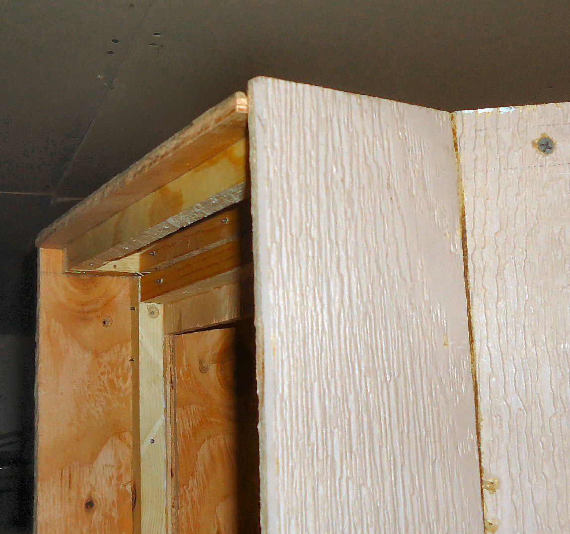
Today I worked on the filter frame and the sloped back piece.
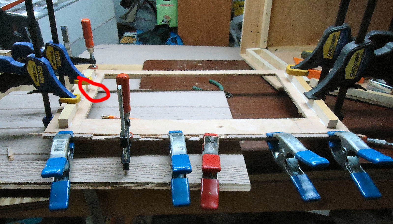
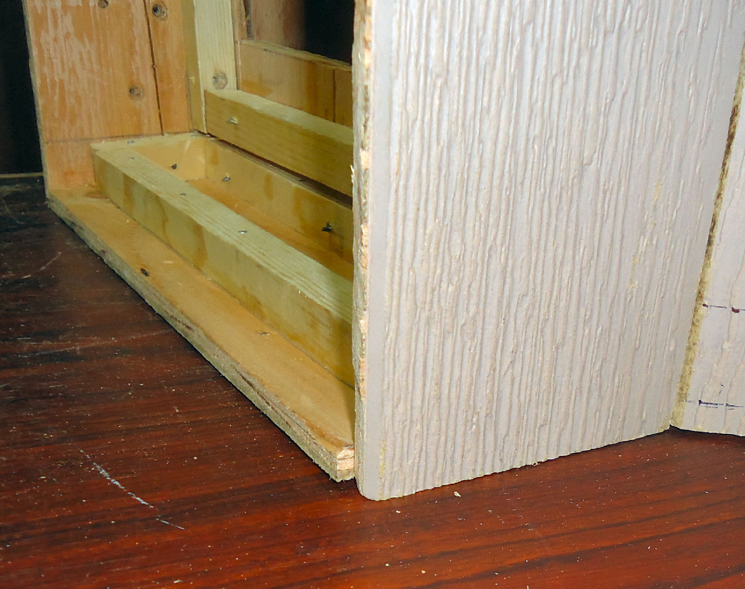
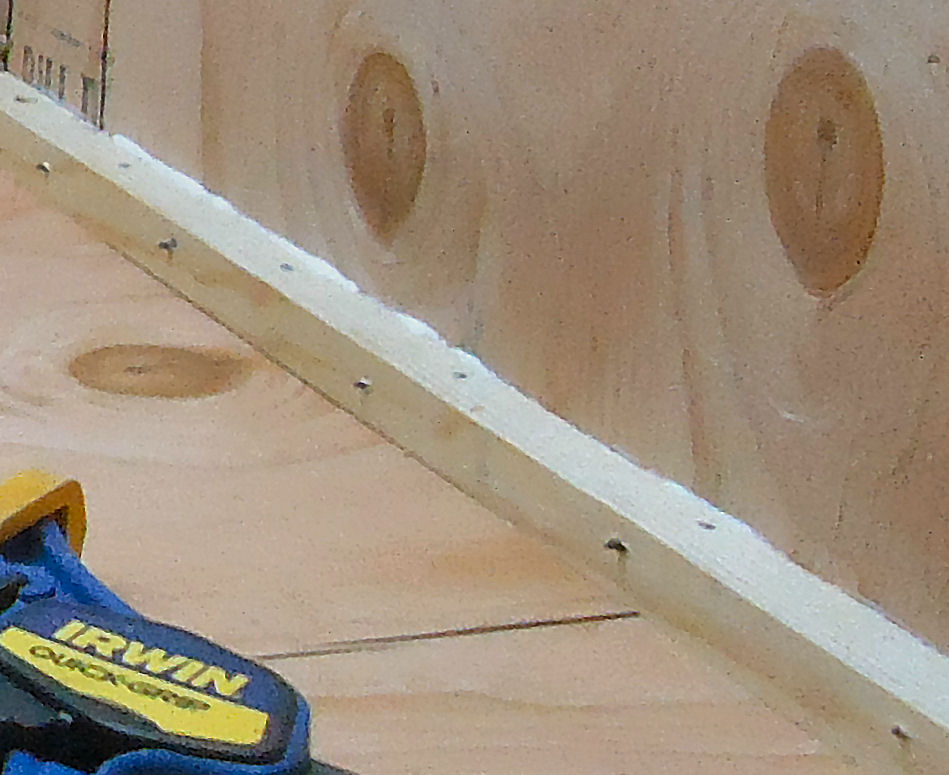
When I was assembling the sides, the filter frame broke along one of the "plank" joints. To fix this and reinforce the other joints, I glued two glue strips on each side at the back of the frame. I also didn't notice when I was cutting it out that the siding lap joint was along one side. Rather than cut a new one, I cut a section of the matching lap off the other side of the ply. Unfortunately, it fell into several pieces! I went ahead and glued the large pieces to the frame. The red circle is the break. There was enough of them to supply a firm seat for the glue strip along that side. Here is a picture of all the parts clamped together.

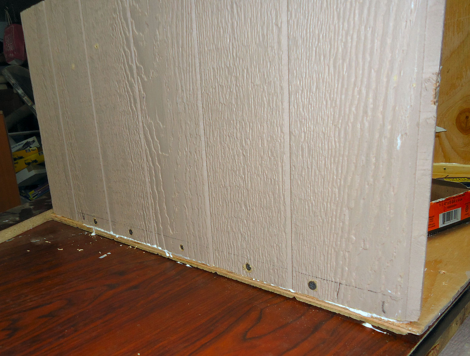
Because the filter will be sitting against the front of the frame, I countersunk for the screw heads, before I installed it. I'll go back when I'm done and countersink the screws along the bottom, so that they don't damage the table surface.
I glued and screwed the frame into place. I drilled the pilot holes into the glue strips, after it was in place. This allowed me to fine tune the position.
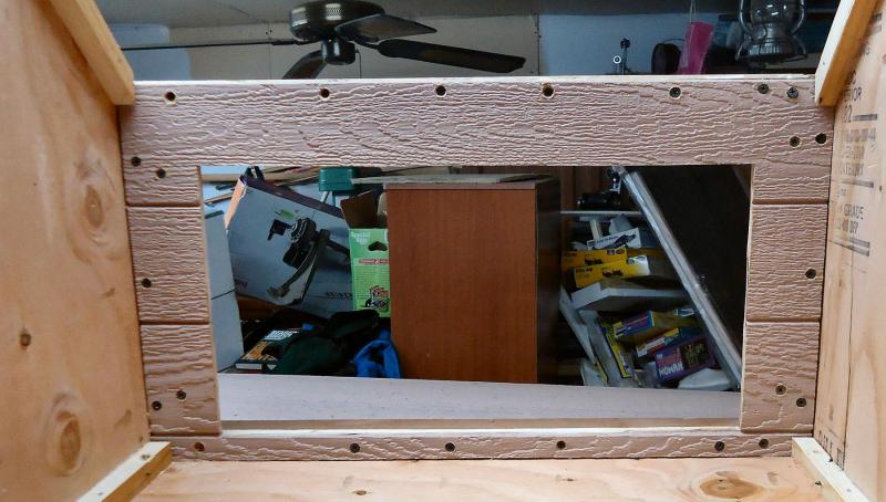

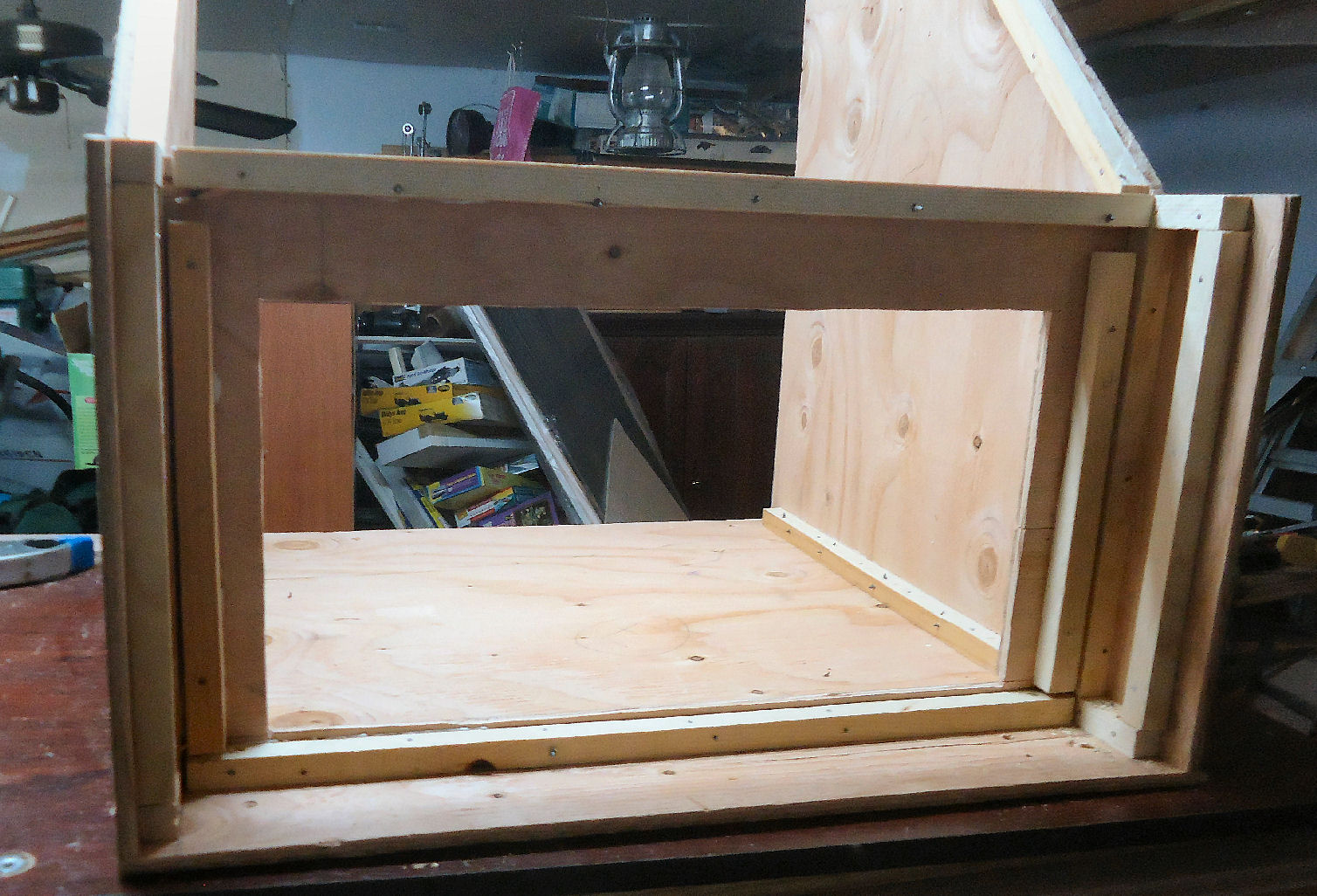
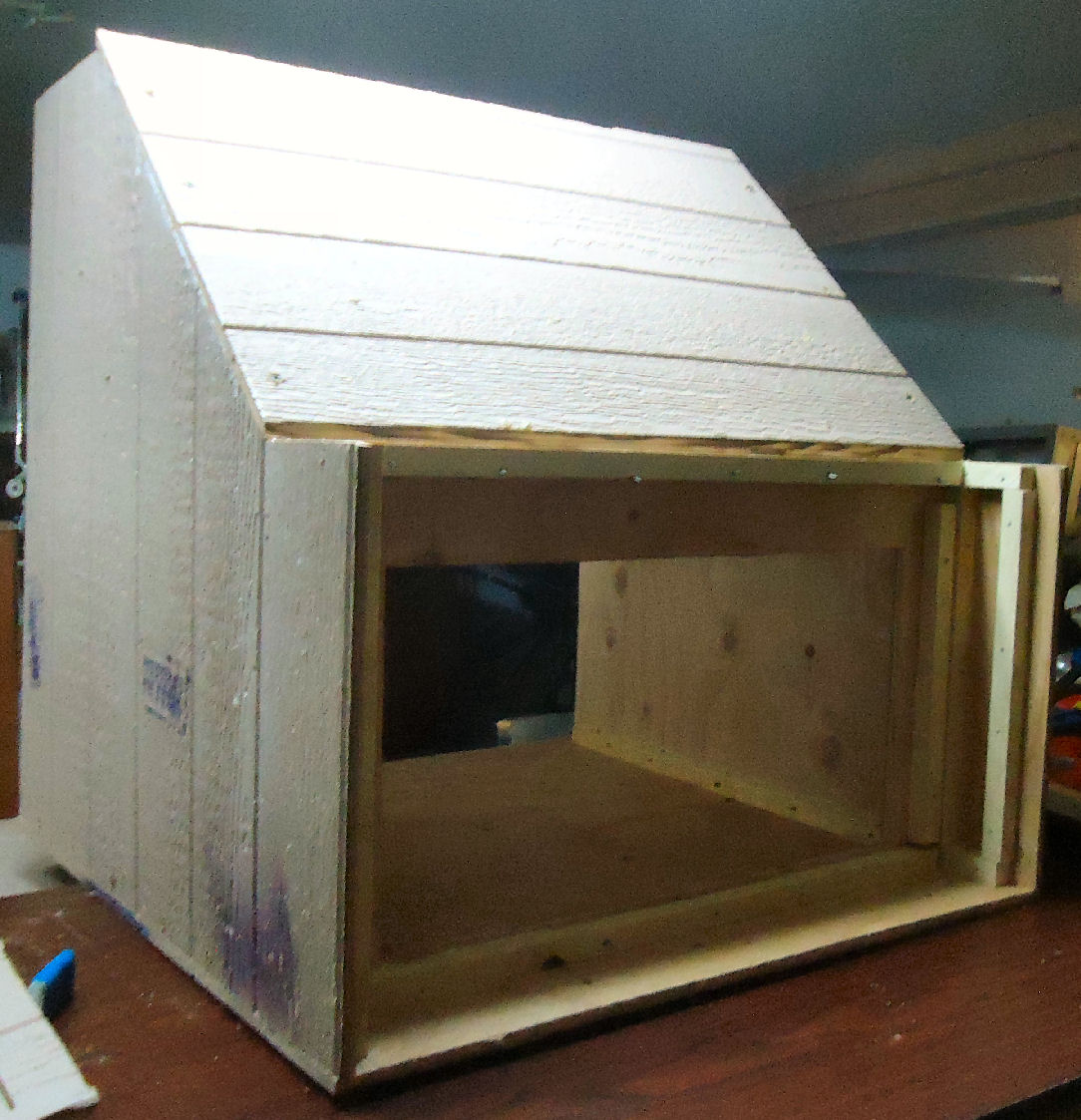
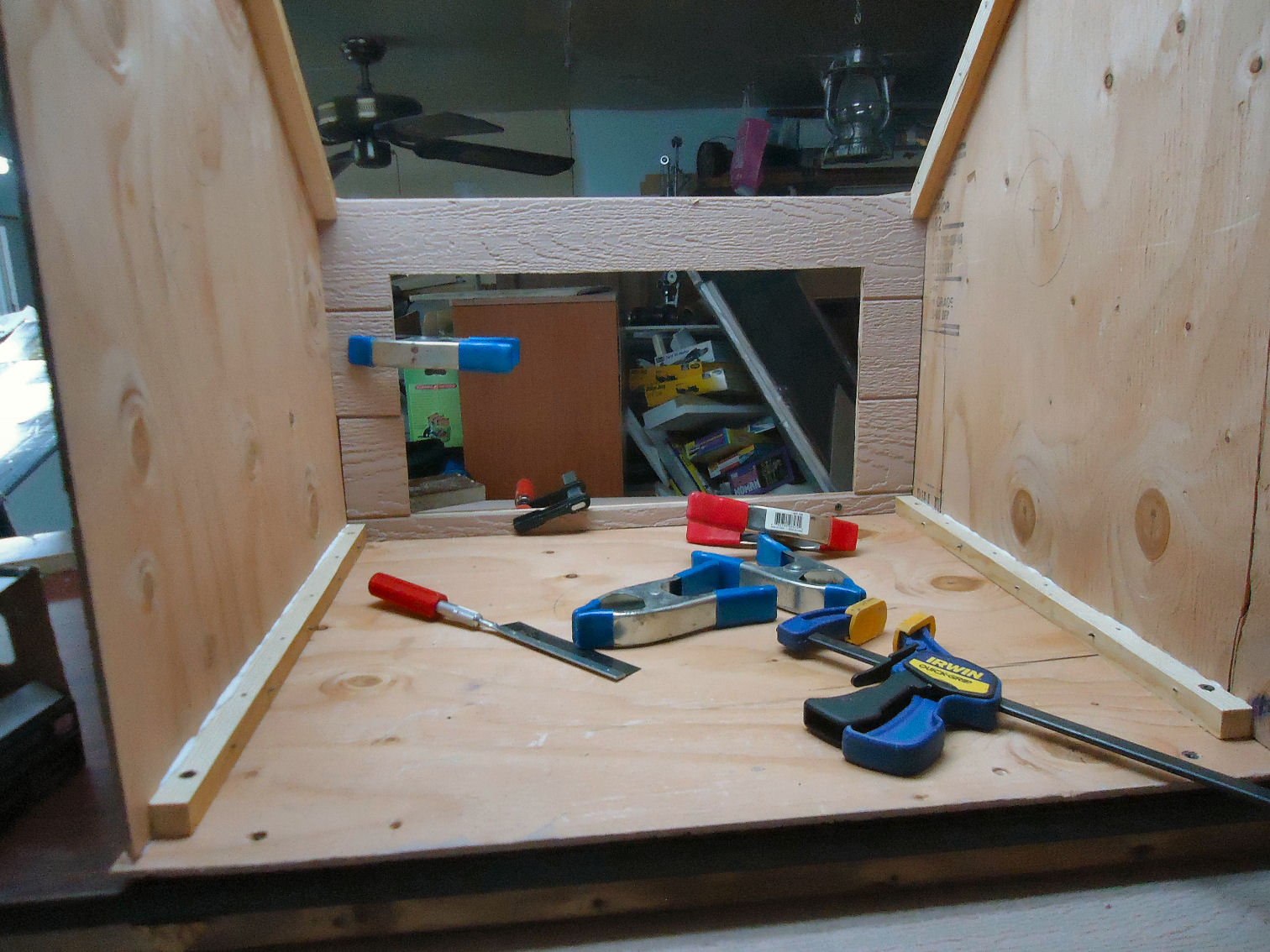
I marked and trimmed the 45 degree angles at the top and bottom of the sloped back. I found that my cutting of the parts was not as symmetrical as I thought, but I got it all to fit.
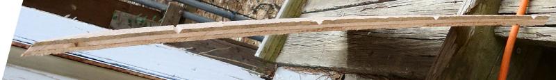
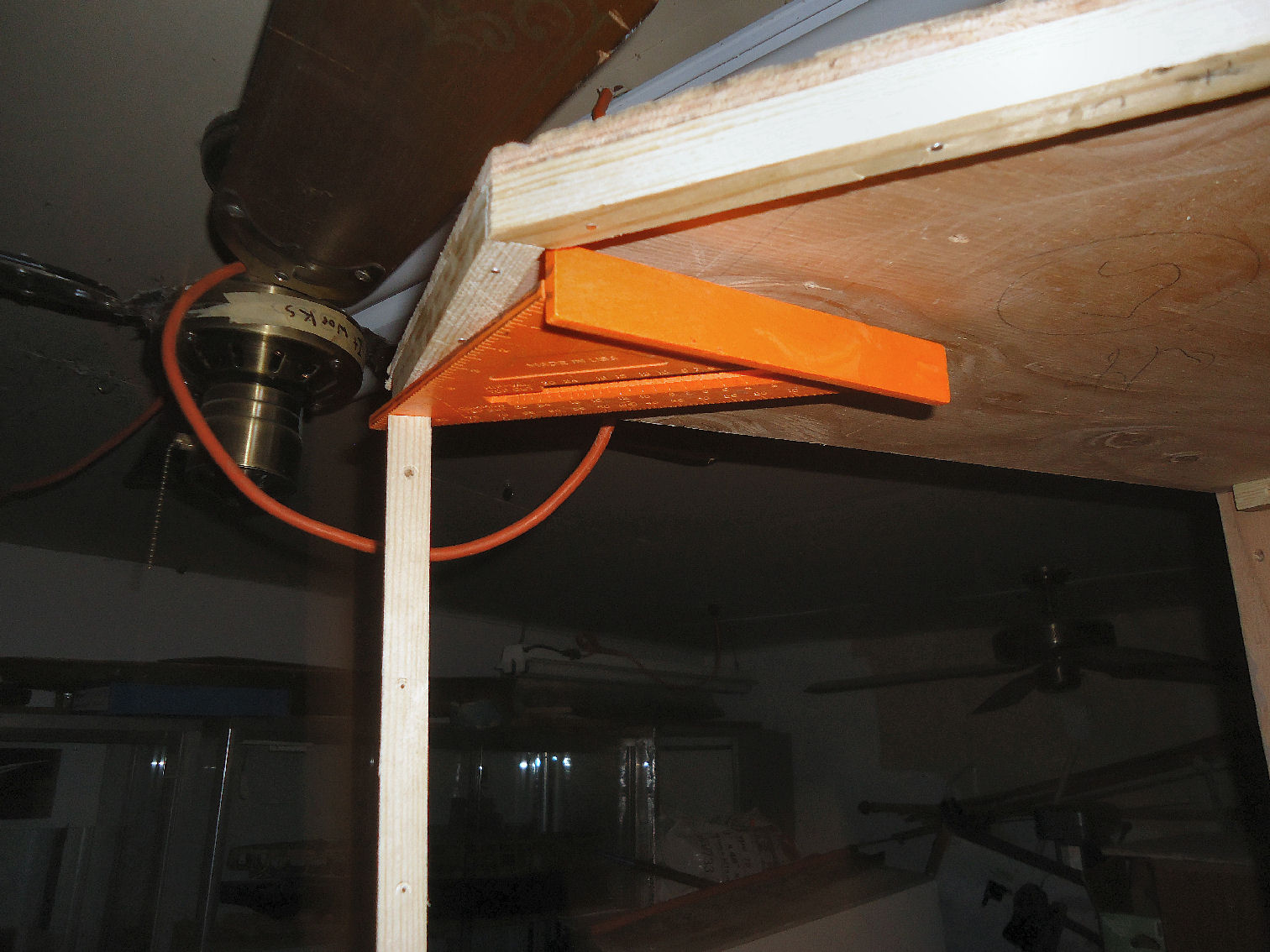
The warp of the sides is causing the top tips to close in toward the inside. To get the correct measurements for the back I had to brace them apart. One of the glue strips for the blower well cap and a square came out to the right length for this brace.

I clamped one side down flat and screwed in that side of the back, then I flipped it over and did the same for the other side. With the holes ready for the gluing, I removed the screws, clamped the first side back down, applied glue and screwed it back together. The other side followed. Then I cleaned up all the glue that got squeezed onto the table top while I was installing the screws.
When marking up the back, I found that the blower housing cap, is 1/4" too short, to match the sides.

The blower wall is 3/4" thick, so I'm going to go with the present cap. I keep repeating to myself, "It's a spray booth, not a piece of cabinetry."
The cap will not be glued to the booth. I'm going to make it removable so I can work in that area, if I have to, in the future.
This is all the permanent assembly I can do right now, I've run out of screws and glue! The blower should be here by the end of the week, so I'll work on mounting it to the 3/4" ply wall.
- GemmaJF, Bill Tuttle, Canute and 1 other
-
4
-
I just did a little more drawing, and a 36" wide booth, for a 14X30 filter, could be made from a single 4X8 plywood sheet. I think a 1/2" thick sheet would be required, not the 3/8" one I used.
- Canute, mtaylor and Bill Tuttle
-
3
-
Kurt;
If I find that the suction is too great, I'll either sell that blower, and buy a smaller one, or build a new booth the full 39" width of the table. The construction has not been too bad thus far, other than lugging my heavy 10" miter saw in and out of the shop.
This booth was built with mostly stuff I had around the shop, but a bigger one should not cost more than $50, with the ply and 1 X 6 board for the glue strips.
One thing that I am going to add, after viewing another booth build on YouTube, is a cover for the front, when I'm not using the booth. It will keep the dust out between uses.
- Canute, Bill Tuttle and mtaylor
-
3
-
2/19
Today I glued the sides onto the bottom of my spray booth.
Before I start, for my mother should she ever read this. Yes, shop horrible mess, you raised me better, suitably ashamed. Sorry. :-)
I started out dry fitting them. The filter frame will not be glued in today, but it is being used as a jig to keep the sides square, and correctly oriented front to back. It is tight against it's glue strips which are already attached to the sides.
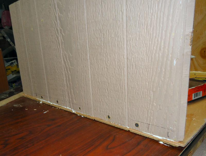
I disassembled the parts and marked the bottom of the sides for where the long strips mated to it. Then I drilled 1/16th pilot screws through the ply. The purple paint was put on by the lumberyard. The panels were damaged, so I got them for 70% off. The paint is how they indicate to the cashier that this is the case. The damage was to the lap joint notches, so didn't affect this use.
After putting the side and frame mount back in I installed the screws. Starting in the middle, due to warp in the plywood, I drilled the pilot holes through the glue strips and ran in the screws. Then, naturally I installed the other side.
I found that both sides bowed in, so I had to clamp the filter mount in firmly, and put a screw in to hold it in place.
I mistakenly installed the glue strips at the back of the booth to the side pieces, so I couldn't put screws in from the bottom, with everything screwed to the table. I used my two long clamps to hold those two joints tight to the bottom. Tomorrow, I'll remove it from the table, put in screws, and reattach it.
One side at the back was twisted in, so I clamped it from the side, another reason the two glue strips should have been attached to the bottom first.
The strips and ply come out to 1 1/8" thick, and my screws are 1 1/4" long. When I'm done, I'll go back with a motor tool and cut the ends flush.

- WackoWolf, mtaylor, Bill Tuttle and 2 others
-
5
-
2/18
Today I glued the corner strips to the bottom of the spray booth.
The booth will ultimately reside on a table with casters, so I can move it around. I have an old table top, that will be used for this.
As I mentioned before the plywood is warped. I don't have deep enough clamps to get to one of the internal corners. So I decided to screw the bottom to the table top, in the position it will be at. This flattened the ply. In addition I temperarily screwed the corner pieces down also. I'll remove all the screws when I go to assemble the booth.
Here is the bottom screwed to the table. I'm left handed, thus the offset to the right. The left hand area will be for storage of the airbrush equipment.
Next I laid down the sides in alignment with the bottom, so I could position the internal corner pieces correctly.
Then I glued and screwed the pieces in place. I found that even with the bottom piece screwed to the table, the screws in the corner pieces were needed to get them to lay down without a gap.
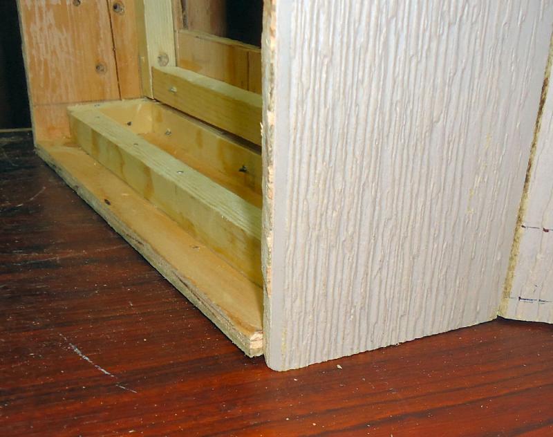
Here's the bottom finished as far as I want to go for now.
I still have to put in the piece for the bottom of the blower bulkhead, but I'm going to do that after the sides and bottom are assembled. Less chance of having it in the wrong spot, if the sides are not perfectly aligned. A good seal here is essential.
I stopped here to let the glue dry overnight.
- Bill Tuttle, Canute, WackoWolf and 1 other
-
4
-
2/17
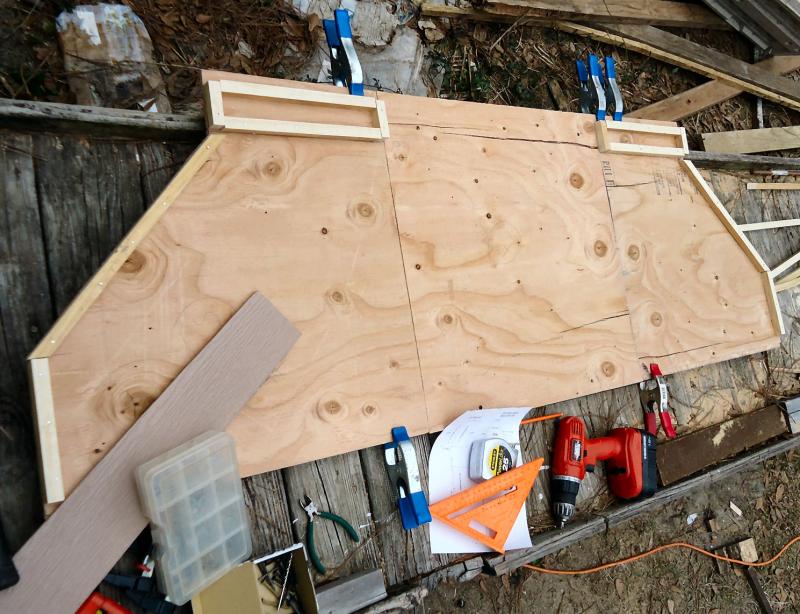
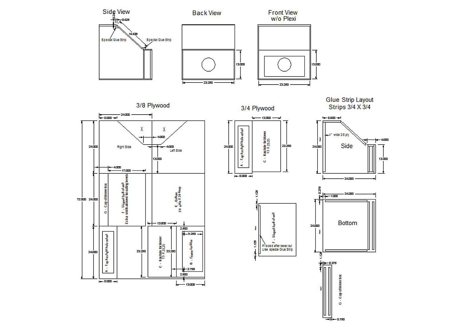
After going over my drawings one last time, and finding a few errors, I started construction on my Spray Booth.
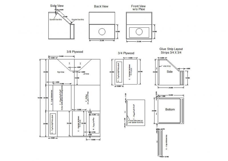
I've cut out all the plywood, and ripped a 1 X 6 into 3/4" strips. The strips are for the corners, to strengthen the joints.
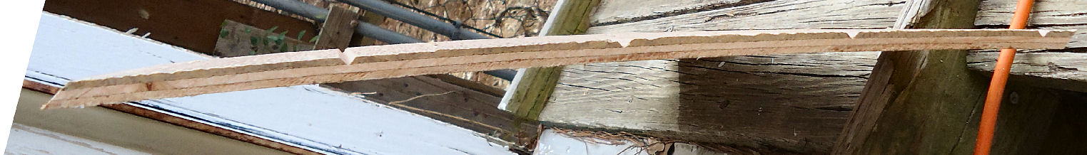
Here is a picture of the sides, with the strips glued and nailed on. The ply is warped a little, so all the clamps are to hold the glue strips on solid, until the glue dries. I'll let them sit overnight, and do the rest tomorrow, when I the clamps are free.
The glue strips are sitting over at the left of the ramp. The rectangular arrangement of strips are for the filter mount and blower bulkheads. Most of the case is 3/8" ply (I would have preferred 1/2", but I had the 3/8"). The blower bulkhead is 3/4", as I felt the 3/8" was too thin for this. The notch on the larger end of the one side is a lap joint in the plywood. The ply is 3/8" exterior siding.
-
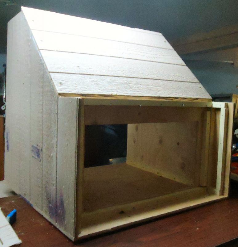
2/16
After looking at a few spray booths, and plans, here is what I'm planning on building. The top has a cutout for a light, I'll put plexiglass in the opening. The top hinges up so I can have more access to the top of the model, or to clear masts, if needed.
The front lip will also be a plexi piece. I think I'll use plastic wrap as an inside cover to both clear parts. I can strip it off and replace it, when it gets coated.
-
2/15
Today I had an epiphany. I've been shopping around for a fan to use in a spray paint booth. I'm going to be using acrylic, so "explosion proof" is not a neccessity, even if I could find one. The internet sites say 500 CFM. Seems a bit high, but start there So, I've been looking at the squirrel cage type with the motor outside the case. Non explosion ones on Ebay with ~150 CFM go for about $60 US. I next thought of using an old dryer blower and motor. Used driers are about $100. I stopped and asked about broken ones at the local places, $35 or more.
Then I remembered the old electric leaf blower that has been dragging around my shop for 6 years, that my wife bought at a yard sale. Squirrel cage, motor outside the blower housing, and lots of CFM. I think I have a volunteer!! I'll probably end up building an outside box to house it, to cut down on the noise, but for now construction can begin.
After some discussion, about 500 or 600 CFM being way too much flow, I found a 250 CFM blower on Ebay, and bought that. The leaf blower idea, though, did get me moving on construction.
2/15
The trouble with the regular hood and bath fans is that the motor is in the air stream, and the vapors (if solvent type) can deteriorate the insulation. The squirrel cage hood fans run about 30 to 50 CFM, too low.
You can get new SC fans with about 130 CFM for $60, but if that is not enough, I've wasted the money. The leaf blower is rated 600 CFM. If that is too much I can ramp it down, to find the right value. A 500 CFM new fan runs about $150.
A drier runs about 130 also, if I can find a free one, I can try that later.
-
Started a new thread about the construction of my spray booth. I started detailing it on the “What have you done today” thread, but figured that that was to much info to clutter it with.
I’m going to put the earlier postings in with the date I posted them, then continue in this thread. So the beginning may be somewhat choppy, stick with me.
-
-
-
-
To Walmart we will go. To Walmart we will go.
- Canute, Nirvana, Nunnehi (Don) and 1 other
-
4
-
-
Nice setup for the mast drilling, think I'll use that setup.
- Overworked724, Sea Hoss and Elijah
-
3
-
-
In the model railroad world, there is a standard, open source, program, universally used in programming the digital locomotive controllers, of all brands. Some SOB programmer copied the code, changed a couple areas, and copyrighted the whole thing under his name, then sued the open source group for infringment!!
it took a couple years and a lot of bucks, to get it overturned.
- mtaylor, Ryland Craze, WackoWolf and 2 others
-
5


Working Skipjacks of Deal Island
in Book, Monograph and Magazine reviews and Downloads. Questions and Discussions for Books and Pubs
Posted
Thanks for the heads up. I just ordered it!!