


thibaultron
-
Posts
2,728 -
Joined
-
Last visited
Content Type
Profiles
Forums
Gallery
Events
Posts posted by thibaultron
-
-
-
-
-
The only thing about the kit, is I would reca0end not applying the copper tape. A US/Colonial ship of that period, was unlikely to be coppered. The British were just starting to copper their warships about this time (1780). Coppering was very expensive, and experimental at this stage. A private builder was unlikely to be using it.
I will be following this build. I love the Baltimore Clipper type ships!
-
-
-
-
My thoughts on the paint/no paint options. If you were building a plastic model of, say a model "T", or a ship, would you leave it the raw plastic color, or would you paint it? I would leave the wood parts with a clear coat, and paint the other parts the correct historical colors.
- Torbogdan, vossiewulf, WackoWolf and 5 others
-
 8
8
-
-
For the problem that the surface in contact with the balloon/bag is smooth, perhaps cover the "mold" with similar cloth, apply the paint/epoxy, etc., let it set then spray it with some sort of mold release. After that put the real sail on. that way the mold surface would be textured, not smooth, and both sides of the sail would be textured.
-
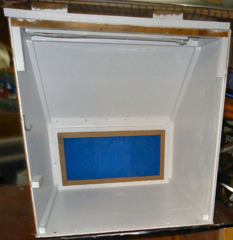
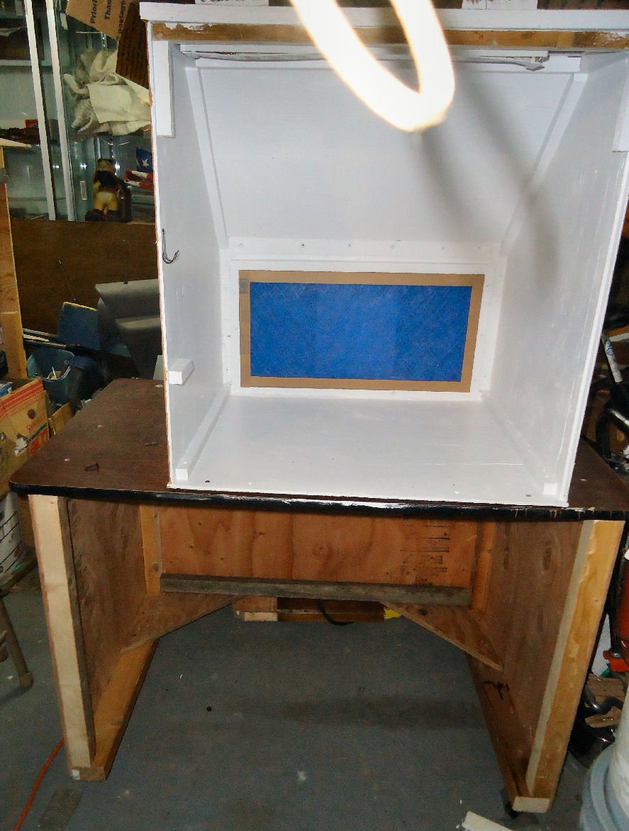
Here are some pictures of the finished spray booth:

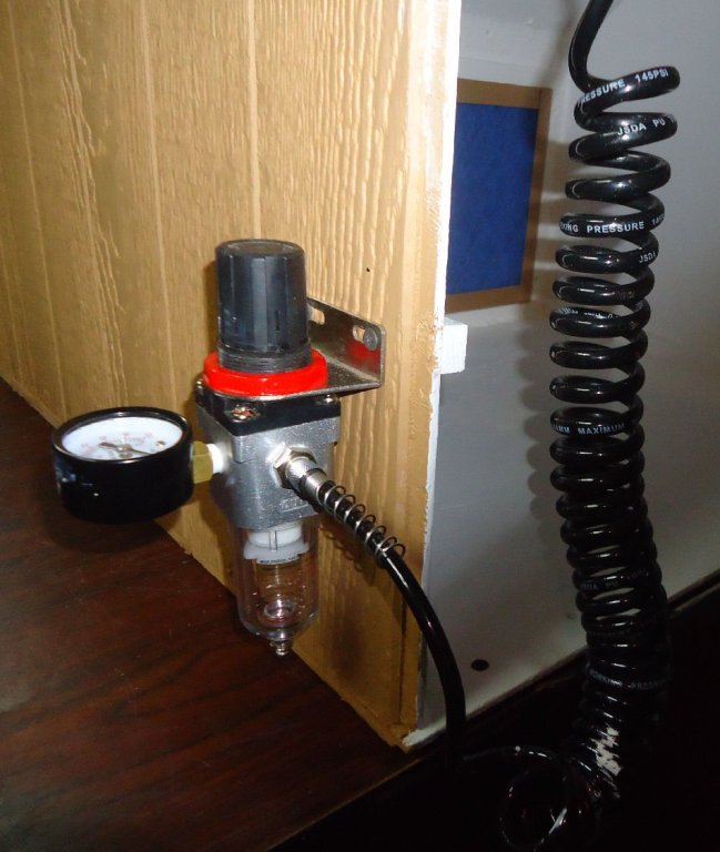
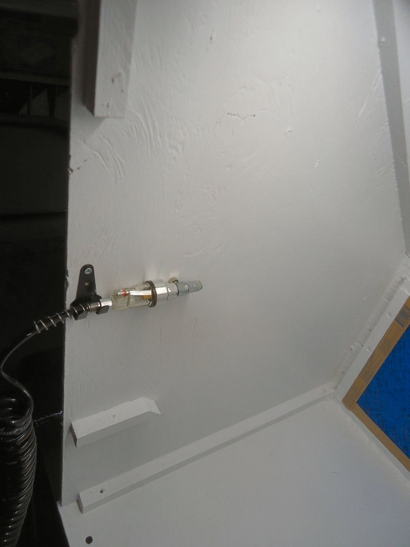
These are a couple of pictures of the airbrush mount, and the regulator mount. The short length of glue strip is there as the regulator mount screws were longer than the ply was thick.

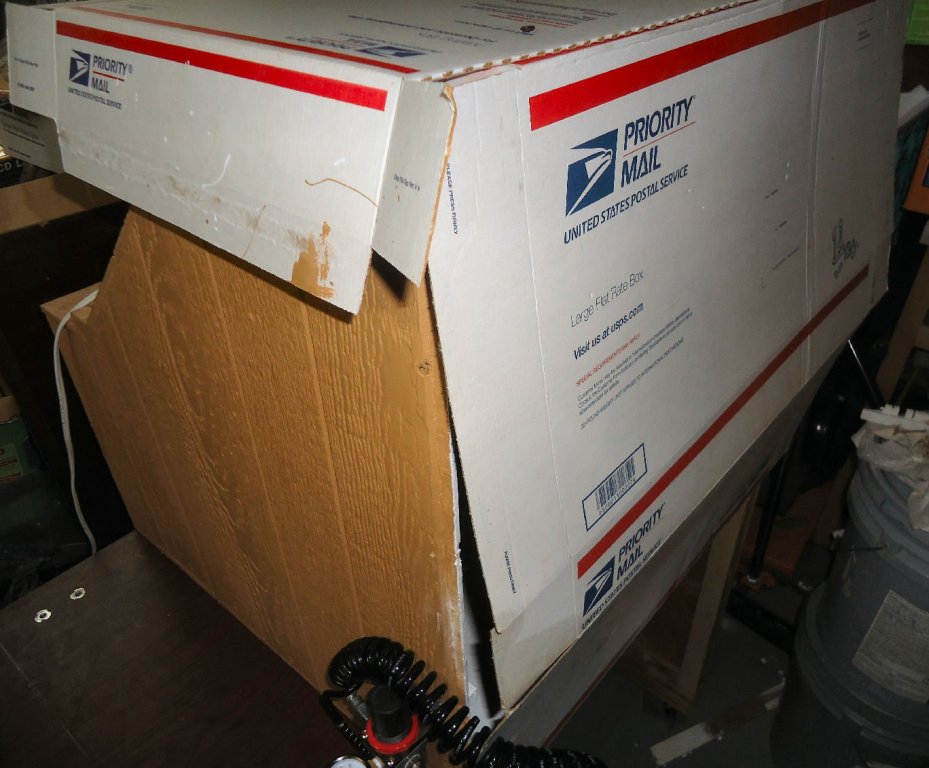
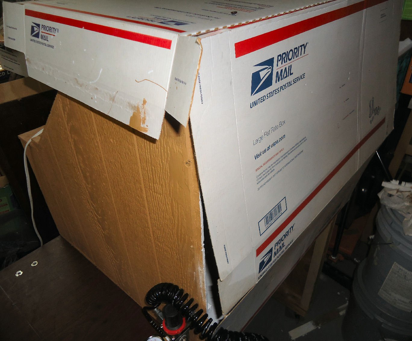
I made a temporary dust cover for the booth out of a couple boxes, that I used as drop “cloths” while painting the booth.
-
Thanks for this tutorial! I think I'll use this method for my 1/64th Skipjack, that I may even have time to get back to soon.
- FrankWouts, Altduck, BETAQDAVE and 4 others
-
7
-
Could the sound have been lessened by the blast being outside the hull?
- trippwj, Chuck Seiler, jud and 1 other
-
4
-
If you go directly to Google Translate https://translate.google.com/?sl=la
You can type or paste in the web address, and it will translate the entire page.
- mtaylor, Canute and flying_dutchman2
-
3
-
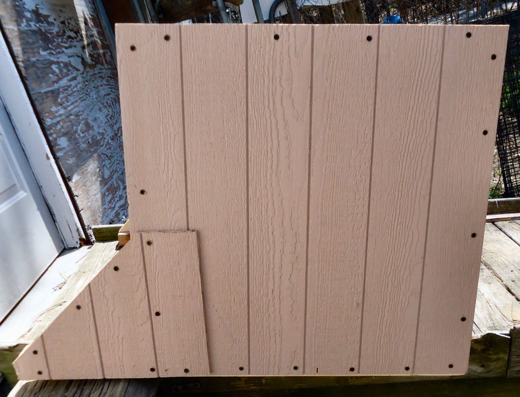
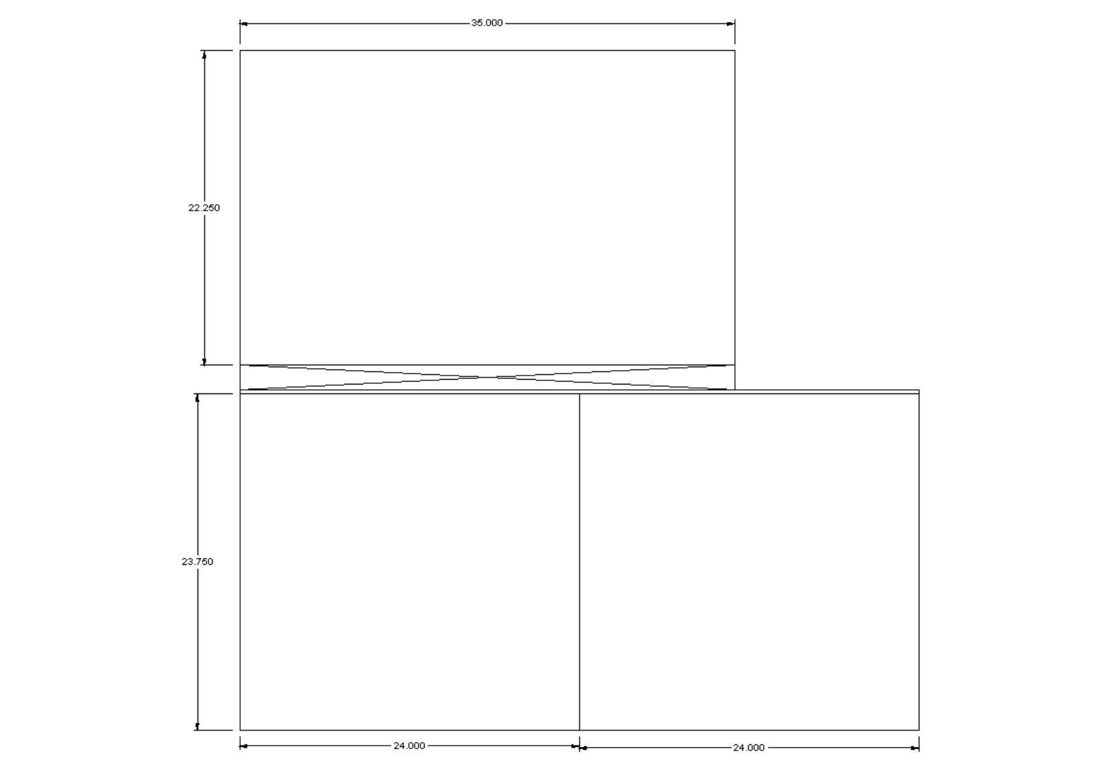
Booth Table
I built the base for the table today. I didn’t attach the table to it. I want to attach the casters first, and I haven’t bought them, yet.
I designed it for the larger 3’ wide booth, just in case. The wider booth is 28” deep plus 5” for the blower. So, I made the base 33” deep, so that the whole assembly would not be back heavy, with the blower hanging in mid air. The smaller booth comes to 29” deep. Maybe later, I’ll cut the base down, if I stick with the smaller booth.
Here are a couple pictures of the drawing.
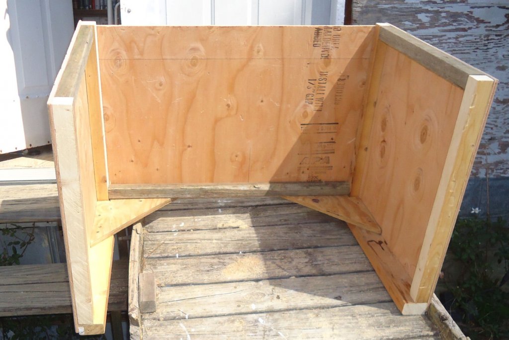
The first is the lumber frame, without the casters. The table top is only 24” deep, therefore I made the main section of the base this deep. Happily, there was just enough of the 3/8” plywood sheet left to skin the back and sides. The bottom of the base extends past the main section to give me the 33” deep footprint I wanted. The width of the base was determined by the 35” width of the top of the remaining plywood.
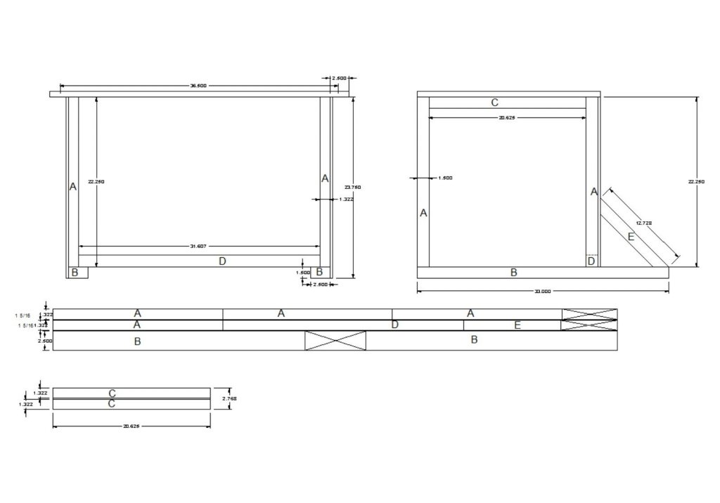
In my normal frugal mode, I found a 74” long piece of 2 X 6 and a length of 2 x 4, that I ripped down to make the frame pieces. Note that the 2 X 4 also supplied the second piece “E”.
Here are the cuts for the plywood.

This is the resulting assembly. I ran out of long screws, and reused the pieces cut from the booth sides to attach the “E” parts. The angle was not quite the same, but it doesn’t look too bad.
I used a couple of pieces of ¾” plywood to reinforce the back corners. These were recycled from an earlier project. Waste not, want not.
-
-
-
-
-
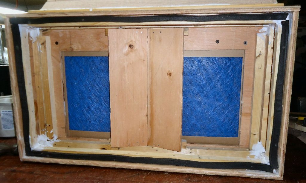
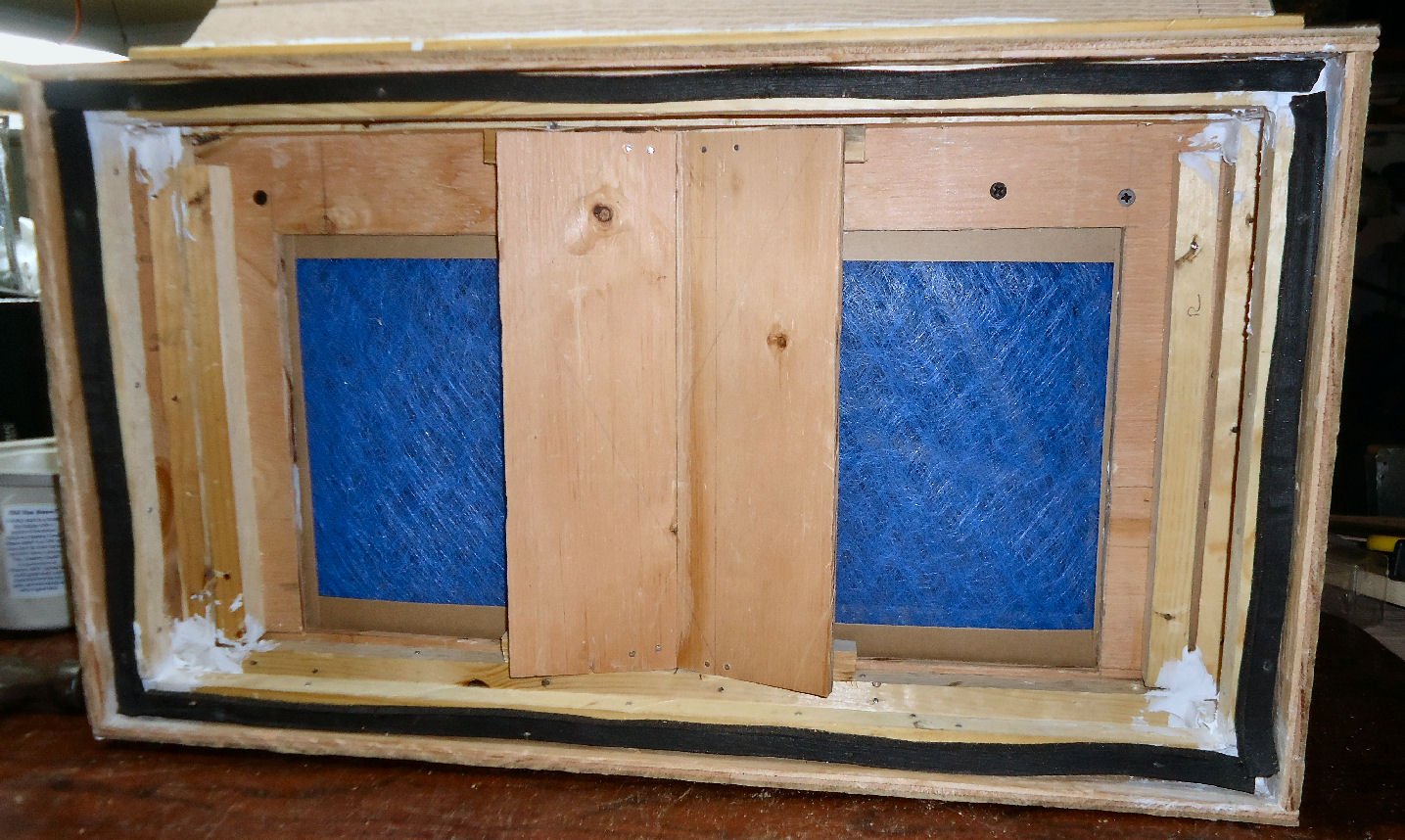
Was finally able to do some testing of the booth today. Unfortunately neither my camera, nor my phone give good enough video to show the testing.
However, here are the results:
1. The 250 CFM blower is too big for this size booth, 2' X 2' X 2', but it does not suck the paint stream when I paint, so, for now, I will use it as is. If I was to do it again, I'd get the 130 CFM blower.
2. The blower is also, I'm sure loader than a 130 CFM unit, but it is not objectionable. My cheap Harbor Freight compressor, on the other hand, is objectionably loud though! I need to get a long hose at put it in another room.
3. The baffle I added, helped in distributing the air flow evenly across the filter.
4. When I did a smoke test, with incense, there were no blowback areas anywhere in the booth. The smoke was drawn directly back in a straight stream.
5. During the summer I will have a nice breeze blowing past me! In the winter, maybe not so nice!
6. I think I will simply direct the output into a covered bucket, with relief holes drilled in it, for acrylic paints. There was nothing coming out the outlet, nor any smell. If I use solvent paints, then I will vent it outside. The blower would exchange the air in the shop, much faster than either my heating, or air conditioner could keep up with, if vented outside all the time. Another reason for a smaller blower.
7. This size booth is a better fit for my space than a 3’ wide one would be. I have another sheet of 3/8” plywood, though, so I may build the bigger one, just to see if I like it better.
I have to build the table/desk next, and paint the booth. I have some aluminum flashing, white on one side, I may line the bottom with it, just to make paint cleanup easier. I also have to find a light to install in the top.
-
-
-
One thing you did, but didn't mention, is that you used location bumps and indentations in your molds. The readers can see them in the corners of the RTV molds, in several pictures. For those who don't know what they are for, it is to align the molds. If you leave these out, getting them lined up so the casting will not have the two halves skewed, when you take them out of the mold, is extremely difficult.
-
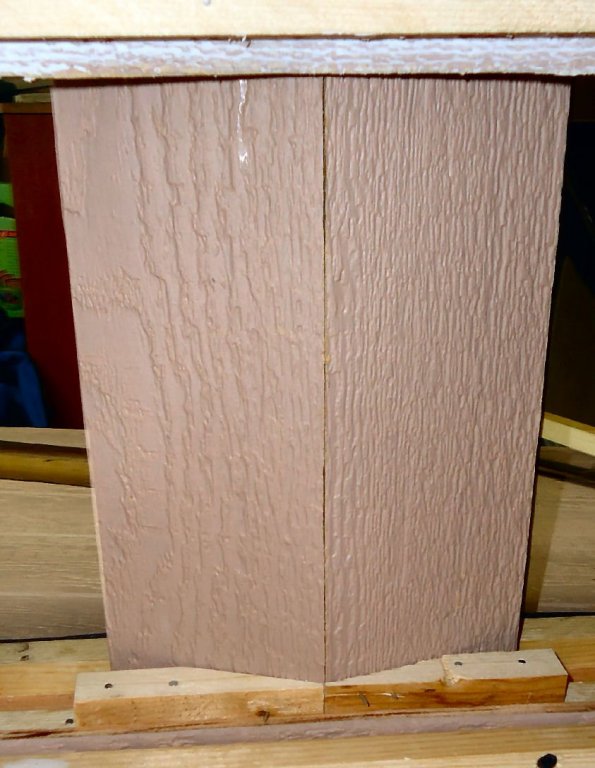
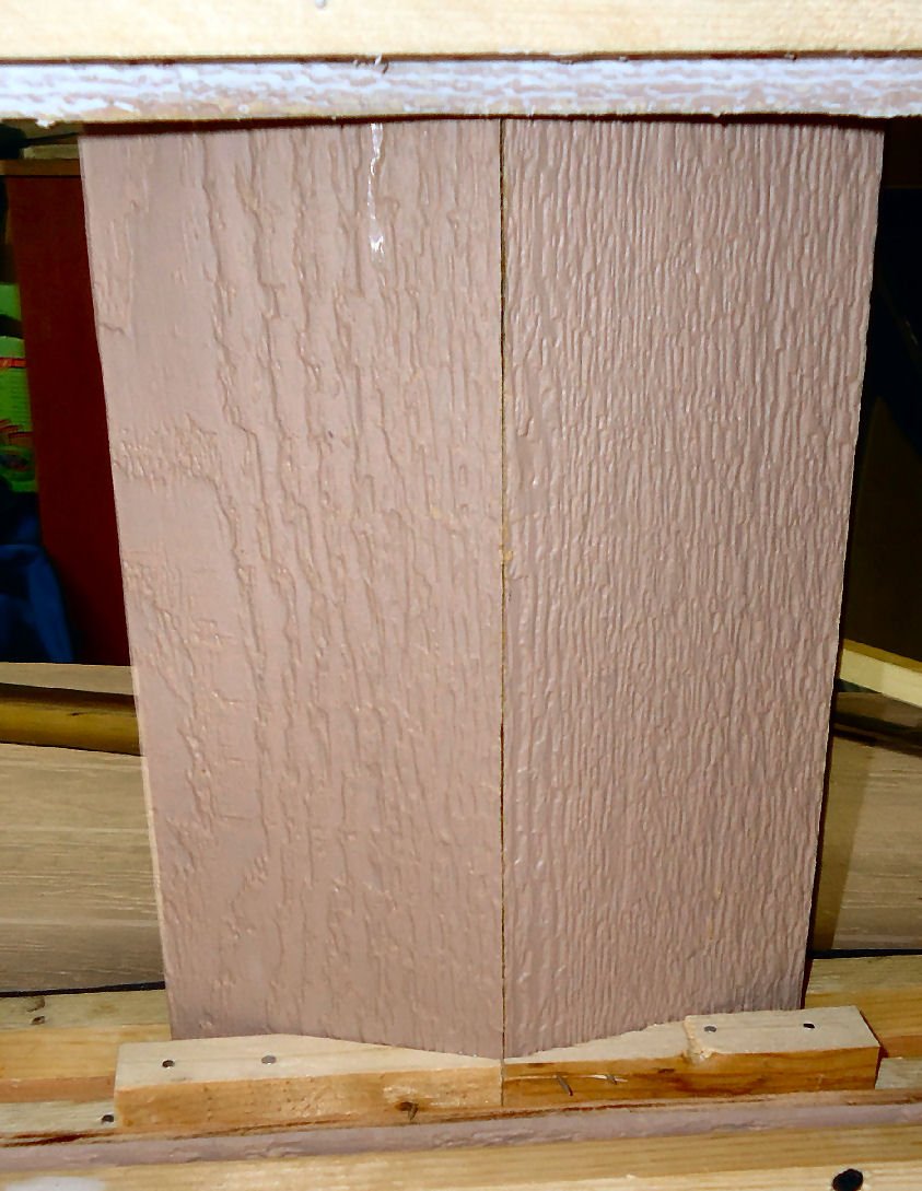
I cut the baffles from some of the left over ply siding the rest of the booth was built from. They are ~4” wide, set at a 17 deg. angle toward the back. I cut 4 short lengths of the ¾” square glue strips to add surface area for the glue. I figured that if I tried to glue just the baffles in, they would end up inside the fan. I used small brads to hold it together while the glue set.
Here are pictures of the baffle I added. It will probably be next week before I can test the booth again. Once again work and family needs.
Baffles from the back.
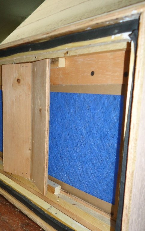
And another from the front.
There is about 1 3/8” gap between the rear of the baffles, and the front of the blower wall. This gives 35 ½ sq. inches of area in the gaps between both baffles and the wall. With about 18 sq. inches of area for the blower inlet, I think this is enough so that there will be little added restriction from the baffle addition.
I bought some incense today, to use as a smoke source for testing, when the time comes, then a paint test.
- mtaylor, michael mott and Canute
-
3


Need tips on deadeyes rigging
in Masting, rigging and sails
Posted
In model railroading we have a saying. "There is a prototype for everything!" We also have a saying, "Never put a window in a chimney!" A couple weeks ago I posted this picture, on my Railroad Forum:
When I was a teenager, I passed this house everyday going to school, and just looked it back up on GOOGLE Maps. Having said that, you also have to consider your viewer. Sometimes making a model realistic, can also make it look odd, or unfinished. In the end, however, it is up to you, what you want in your model.