


thibaultron
-
Posts
2,669 -
Joined
-
Last visited
Content Type
Profiles
Forums
Gallery
Events
Posts posted by thibaultron
-
-
-
-
-
I used Vallejo black on my cannon diorama. I brushed it on, but airbrushing would have been better. you may be able to chemicaly blacken them, depending on the type of metal. There was a thread on this earlier.
- bluenose2, CaptainSteve, Canute and 2 others
-
 5
5
-
If you are going to used tools with capacitor start (many "full" sized tools), I have a tip. In my shop all the wiring to the outlets go through GFI outlets as the first ones in the string, for safety. If you have cap start motors, they can trip regular GFI units. Look for "Motor Rated" GFI units. They only cost a little more, and are designed for such motors. My Atlas lathe with a 1/2HP cap start motor, regularly tripped the regular GFIs.
Dust collection units may also have cap start motors.
-
Construction of a modern Newport replica.
- JAM, Nirvana, skipper1947 and 3 others
-
6
-
Reklein;
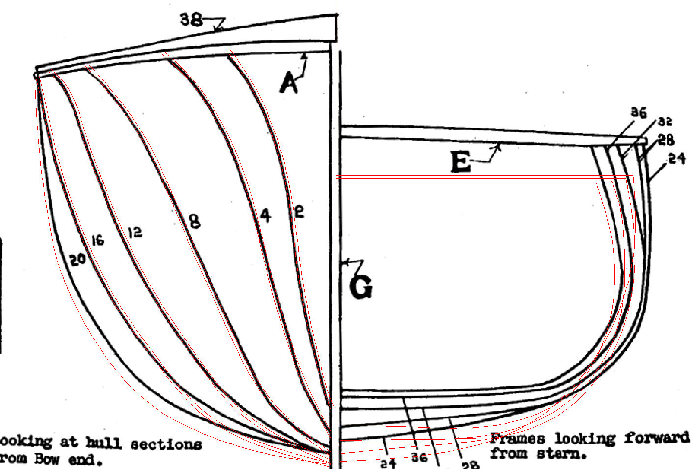
Thanks for the pictures. I looked at the MA pictures, and they left the insides of the ribs with the char, as did all the other buit pictures I could find.
- Nirvana, popeye the sailor, Canute and 2 others
-
5
-
Here are a couple links to other builds, one the DR1 and the others of other Model Airways kits.
http://www.lazuli.com/n_projects/n_dons_projects/n_fokker/index.html#
http://www.modelshipbuilder.com/e107_plugins/forum/forum_viewtopic.php?16206
http://www.ipmsgreatplains.org/camel.aspx
I liked the way the DR1 biuld added some color to the model, but not too much.
I have the Sopwith Camel, DR1, Newport, and Wright Flyer kits.
-
Reklein:
Did you remove the char inside the wing ribs? If so, how.
- popeye the sailor, mtaylor, Canute and 1 other
-
4
-
I too have this kit, and will be following the build. Model Expo is very good at helping modelers, email or call them for an answer to the spar construction.
-
-
-
You can change the color of the render, by either:
1. Actually change the color of the lines in an object, such as the cannon.
2. Change the material the object is "made" from, such as changing the cannon to Brass, and the carriage to Wood.
Both are simple and quick.
-
I just finished on of Model Expo's Naval Cannon kits. Nice large size, and uses several of the technquies you need for a regular ship kit. I added hooks to the gun tackle ends, and used rope stropped, rather than metal stropped, blocks. The later were what was shown on all the drawings I could find.
Model Expo promptly replaced some of the deck strips I messed up.
-
-
-
-
I remember a car restoration show I saw several years ago. They started with a late 60s muscle car, to be restored. As they stripped the body, they found more and more hidden rust. Finally they replaced all the sheet metal, except the piece between the rear window and the trunk!! The modern version of a "Great Rebuild"!
-
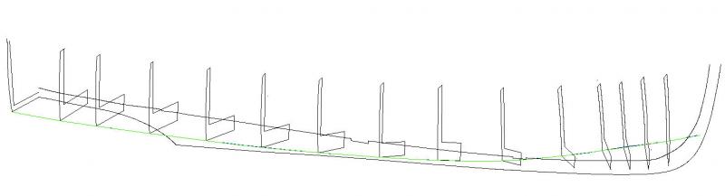
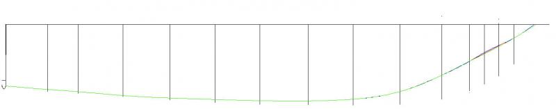
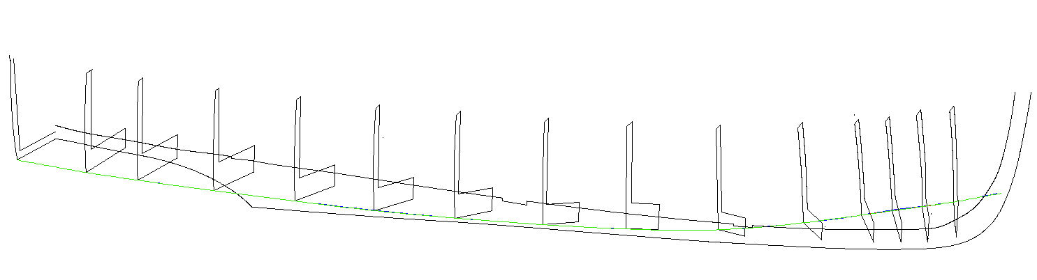
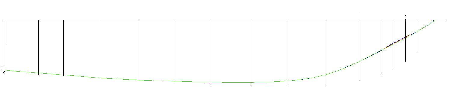
If you can used the 3D, lay out the frames in position, and draw (in DesignCAD) a curved line along them at a fixed height. If the frames are correct, the line should be smooth in all directions, if a frame is out of line, draw the curve skipping it, and see where the correct point should be.
Below is, hopefully, an example. Why do this rather than a physical model? I can scale this to any one desired, and after I do I can used the parallel function to put in the lines taking account of the hull sheeting thickness I will be using.
Picture 1: The 3D frames with a waterline drawn. Note that the lines run along each other, except at the bow area frames.
Picture 2: A top side view: Note where the lines diverge.
Picture 3: A close up of the areas. The blue and red lines where the first and second attempt at laying the lines. Note how they bulge at the second and third frames, from the right. The green line is after I redrew those frames, with the corrected distance from the keel at that waterline. Here doing a model would be close enough for you to get an idea, but look at the next shot.
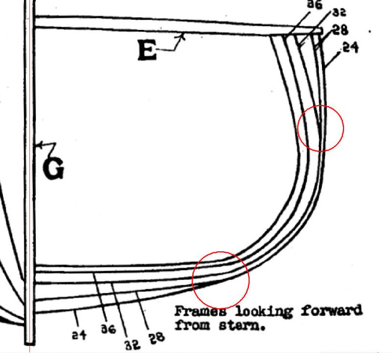
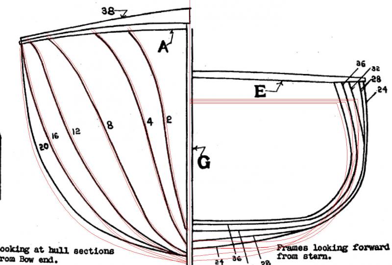
Picture 4; The before frame drawing of the hull lines. Note where frame 28 goes into the curve on one line and comes out on another line, and they don’t meet in the middle!
Picture 5: The before and after hull lines. The fore frames line up fairly well, but look at the aft frames! The original drawing was not even close!! The waterlines were run as in the previous pictures, from the transom to the stem, with a lot of iterations in between.

-
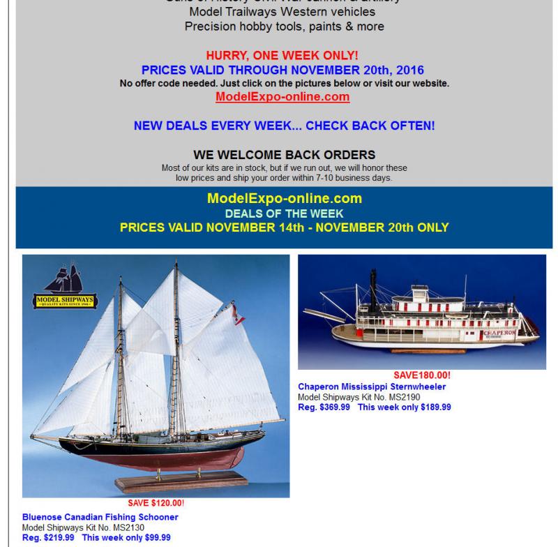
Until tommorow Model Expo has the Blue Nose for $99.99. It is on back order at the moment. The model is of the original Blue Nose, not the reproduction II.
I've attached a screen shot of the ad they sent me. They are presently listing it a $140, not the $220 they show in the add.
-
-
-
-


MS Fair American rigging plan leaves alot to be desired.
in Masting, rigging and sails
Posted
Ships In Scale also sells a CD "Progressive Building" that has a practicum on their former editors build of the her.