

Mark Pearse
-
Posts
706 -
Joined
-
Last visited
Content Type
Profiles
Forums
Gallery
Events
Posts posted by Mark Pearse
-
-
Hi Frank
thanks for the detailed posts. Are those cleats for the mainsail halyards?
Mark
- mtaylor, Canute, thibaultron and 1 other
-
 4
4
-
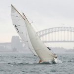
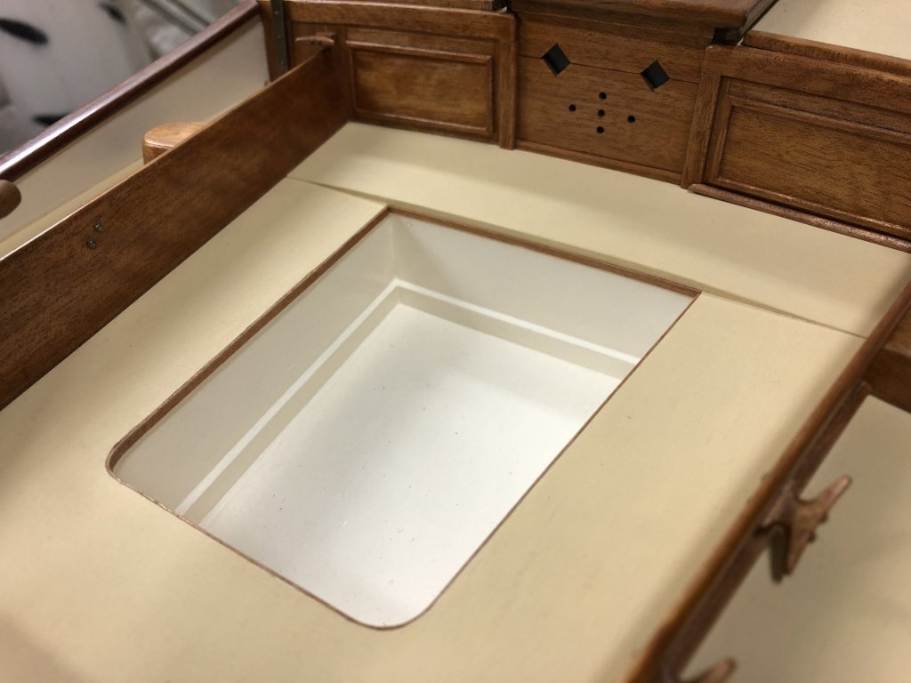
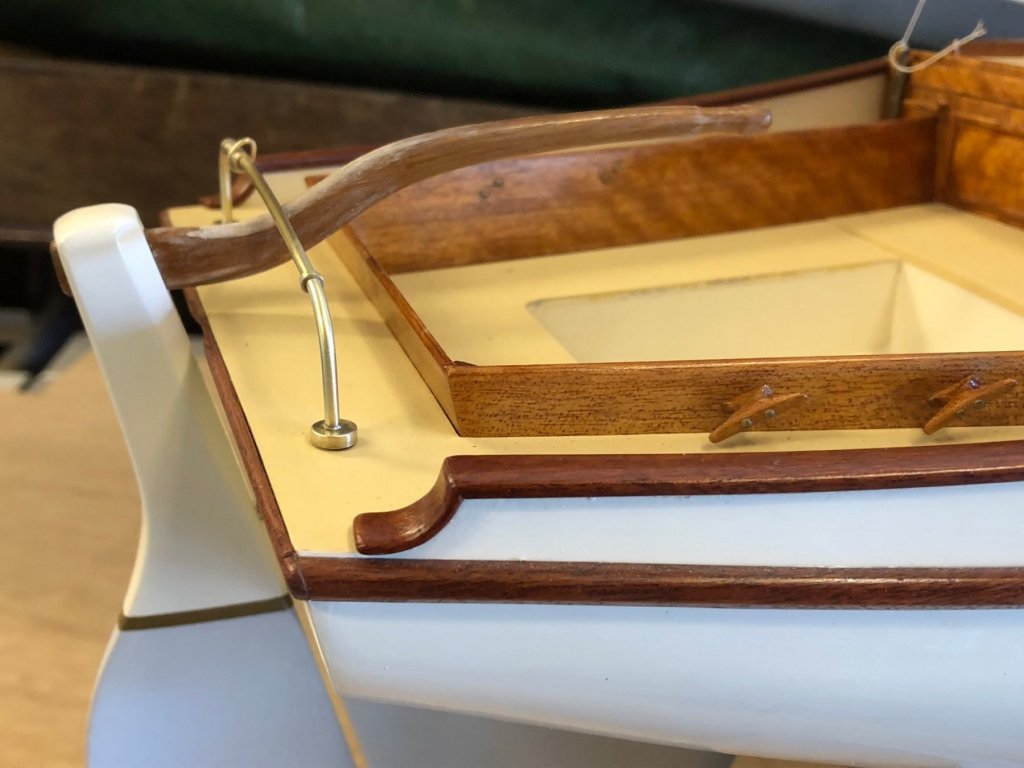
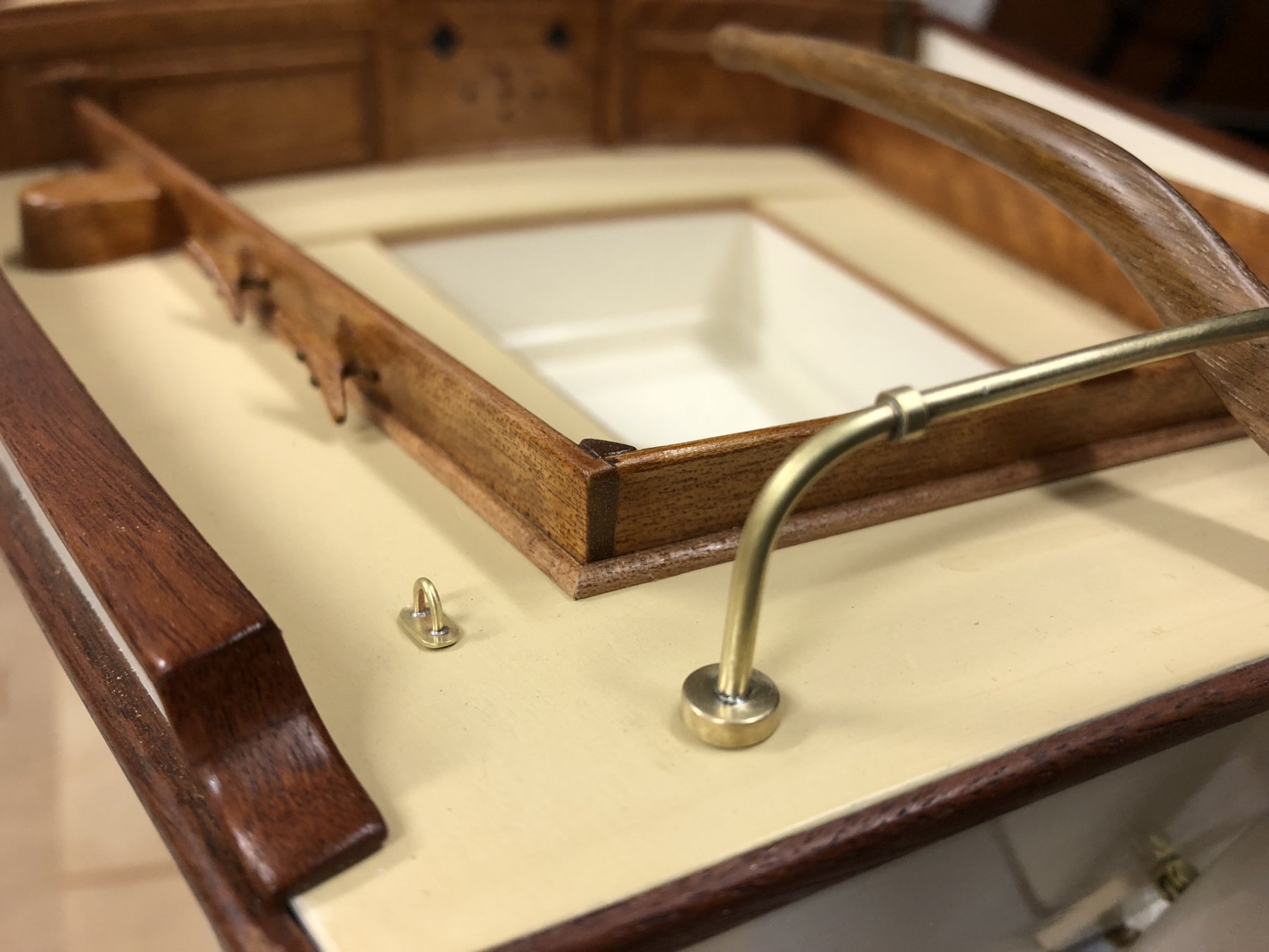
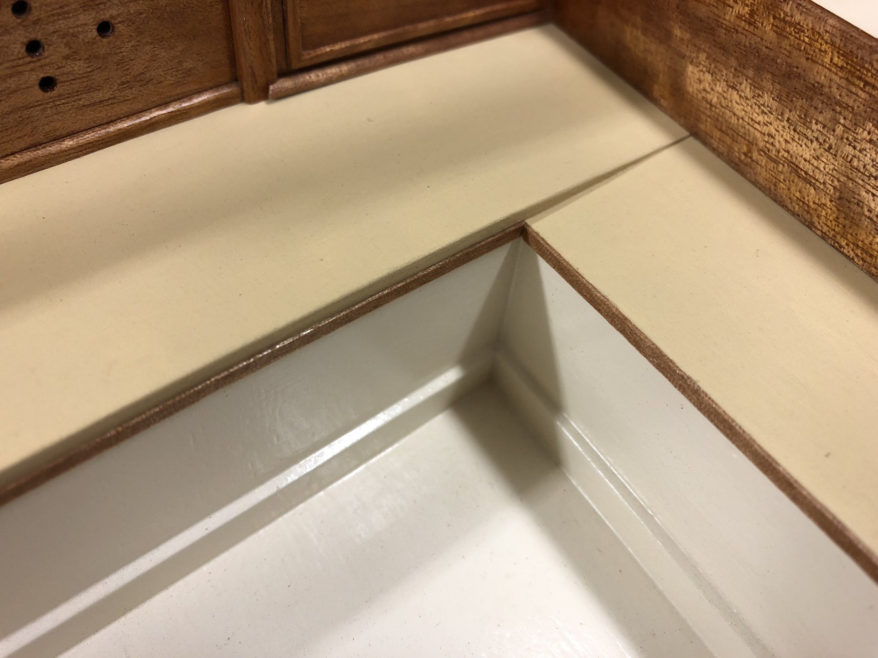
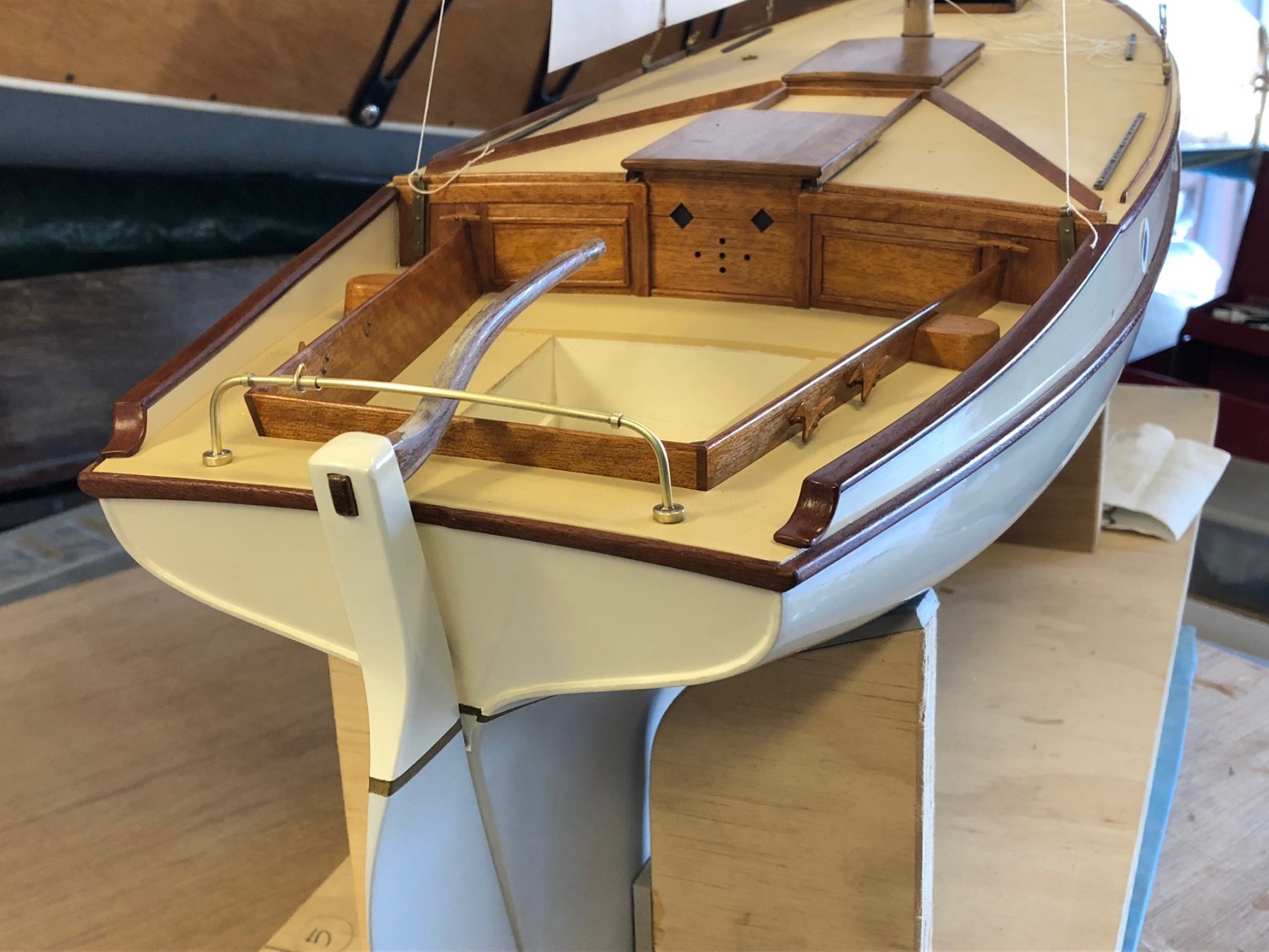
Back to timberwork, I'm trying to finish off the cockpit details. For some time I'd been wondering about the way the outside face of the cockpit seats met the side decks, in some way it looked incomplete so I made up some pieces of quad timber beading about 2x2mm, or maybe slightly under (between 20x20mm & 25x25mm scale). It does look right in some way now, & if the deck was canvas covered, which was probably still done in the 1960s, a bead would help tack down the edge of the canvas. I didn't bead everywhere, but I'll ask someone about it to check details.
The bright brasswork is still unglued.
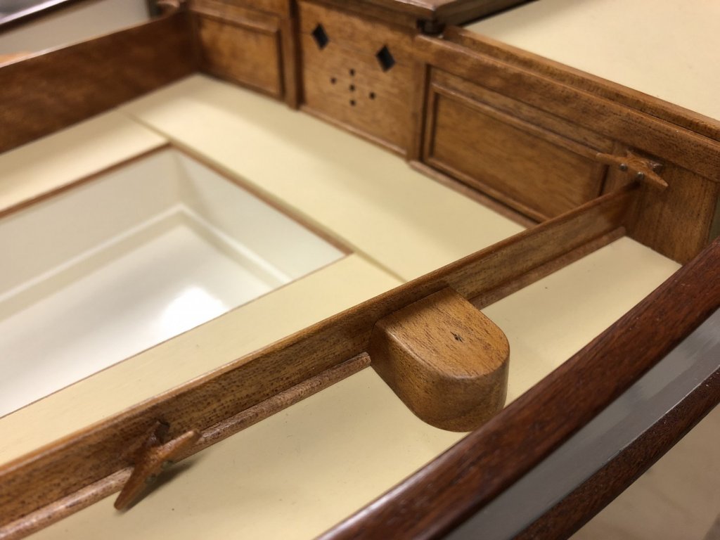
I'm considering putting a quad beading strip right across the forward side of the front cockpit thwart, or perhaps a strip each side leaving out the companionway...see below the piece just sitting there. I'm still unsure about that one.
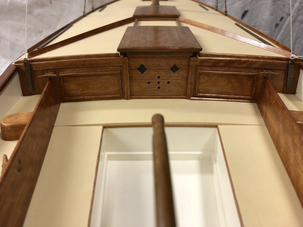
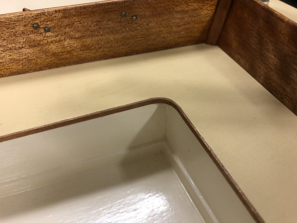
Also I put a timber bead edge on the cockpit seating, it's a finishing detail & also separates the paint colours, For that I tried a thin cut strip of Queensland Maple but it proved too brittle to take the curves (using the cylindrical shaft of the butane torch, heated up). I had a nice piece of Queensland Myrtle veneer - I believe 0.65mm thick, so about 8mm scale thickness - & that was able to do the curves, especially after some wetting.

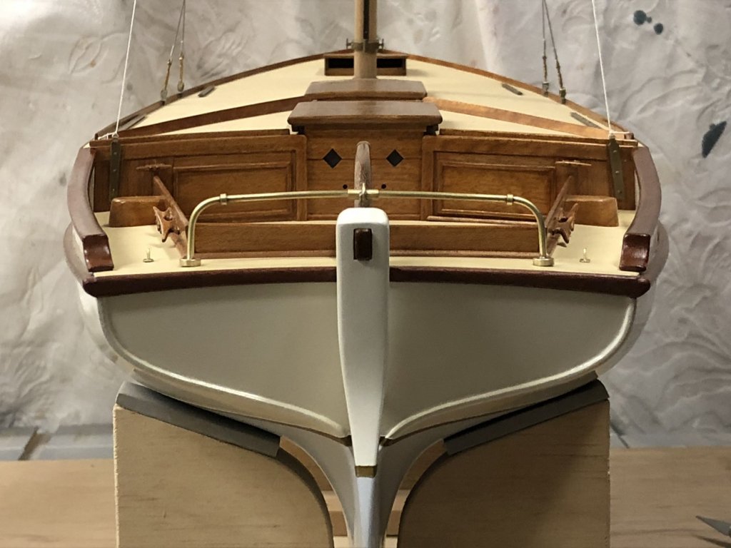
And a nice overall stern view, trying to remove distortion from the lens by standing further away & zooming in. The lines show more accurately.
-
sorry that wasn't clear; yes, photos of your lovely boat Maria sailing in her new home waters.
- popeye the sailor, mtaylor and Piet
-
3
-
sailing photos from your new home?
- Piet and popeye the sailor
-
2
-
Hi Vaddoc
good start with the mast, & another inventive technique that you've thought up yourself - I enjoy seeing how you tackle things. If I can give some gentle advice at this point - to keep taking it slowly on the mast, it's surprisingly easy to lose track of where you need to remove wood & do it in the wrong spot. It might be worth considering marking vertical axes in pencil to give you 4 reference lines.
- cog, mtaylor, michael mott and 1 other
-
4
-
that's good; most yachts that I'm familiar with aren't large, & they have a hatch with a clear width of about 700-750mm; for your vessel there's obviously a lot more people but if the hatch is 'one person at a time' then a yacht hatch width might be comparable. At least maybe that's a good minimum - unless there's some other limitation to width.
-
Hi Steven
on the hatch, it sounds like the lower sole to deck height is less than the rowers' height, so at the bottom of the ladder it might be a good idea to allow enough room for a person to be able to stand & have their head through. If the ladder angle is 30-40º from vertical for the 1.5m or so of height, & the horizontal length of the hatch opening would need maybe another 300mm beyond the foot of the ladder...without doing a drawing I'd guess at 1-1.2m long. Hope this helps.
edit:
Just saw the 'fittings the oars' comment...if that wasn't required to be done very often, perhaps a removable panel to extend the aperture beyond what would be required for people.
Mark
-
that's looking fantastic, a really striking looking vessel indeed
for the head height down below, what height of person are you assuming?
- cog, mtaylor and Louie da fly
-
3
-
Hi John
it's a lovely model, it's wonderful how each stage of a build has it's own pleasures.
Wishes for your good health.
Mark
- cog, Piet, popeye the sailor and 1 other
-
4
-
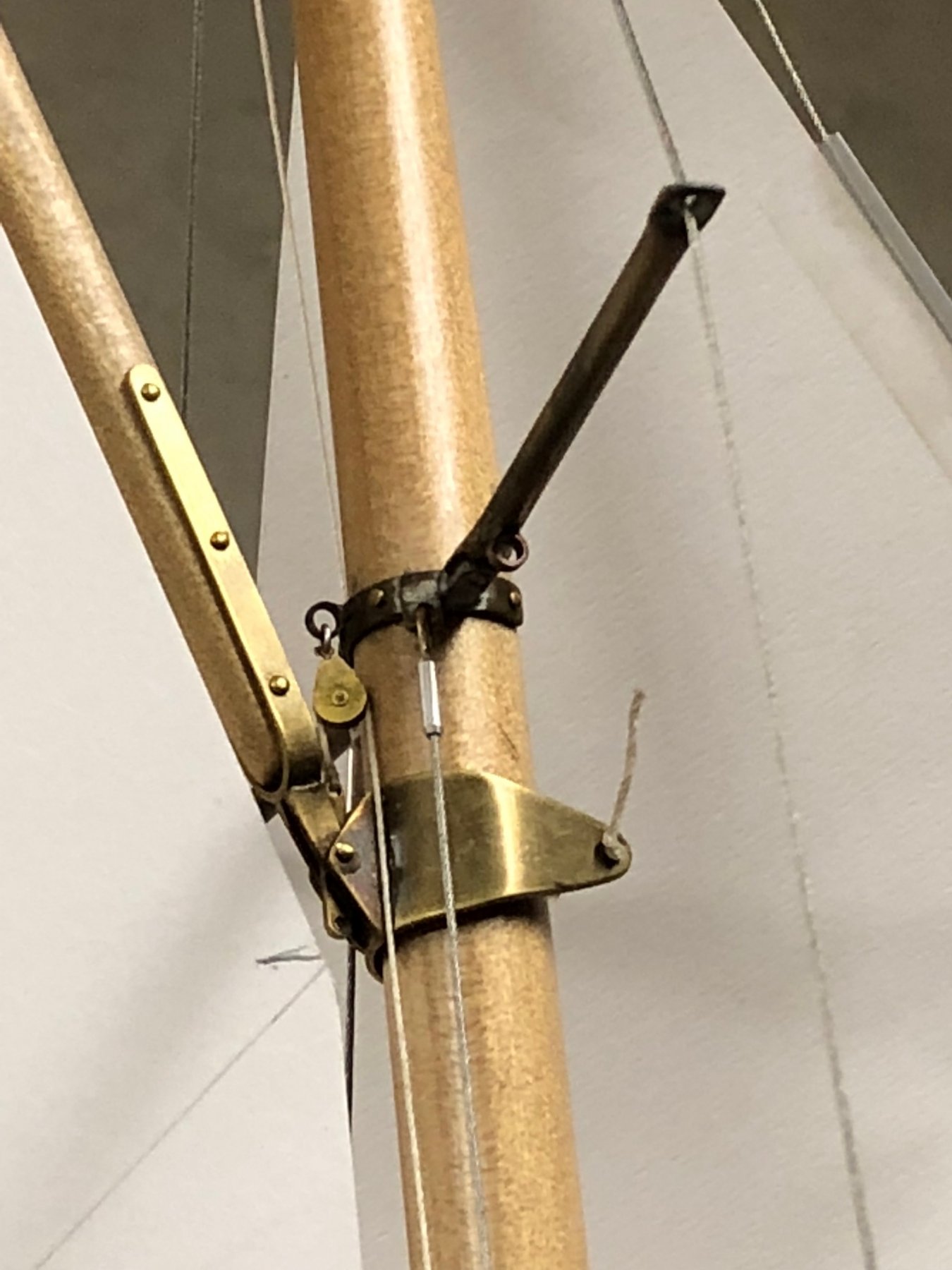
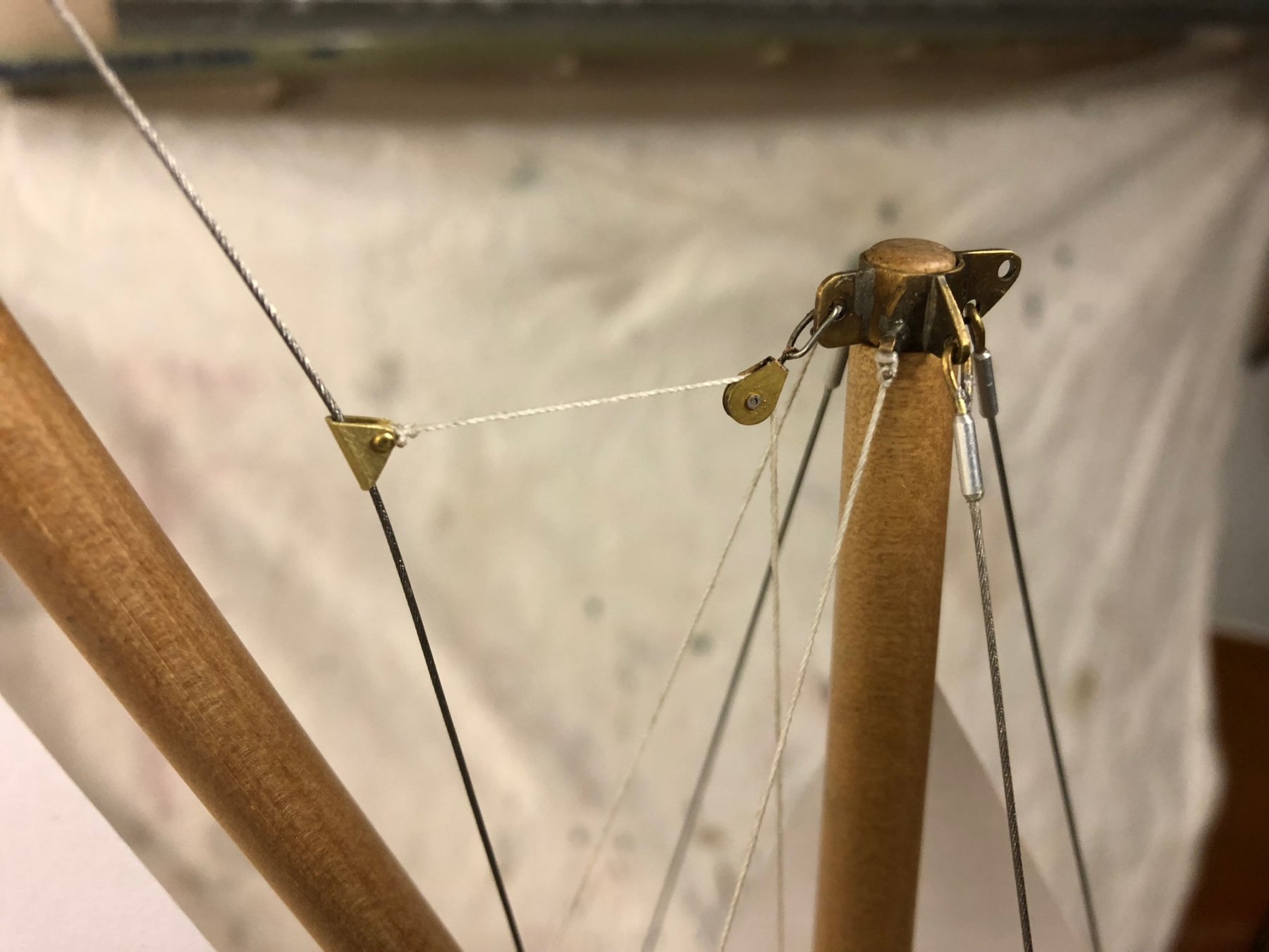
Some details on the rigging done recently. The throat halyard & gaff jaws:
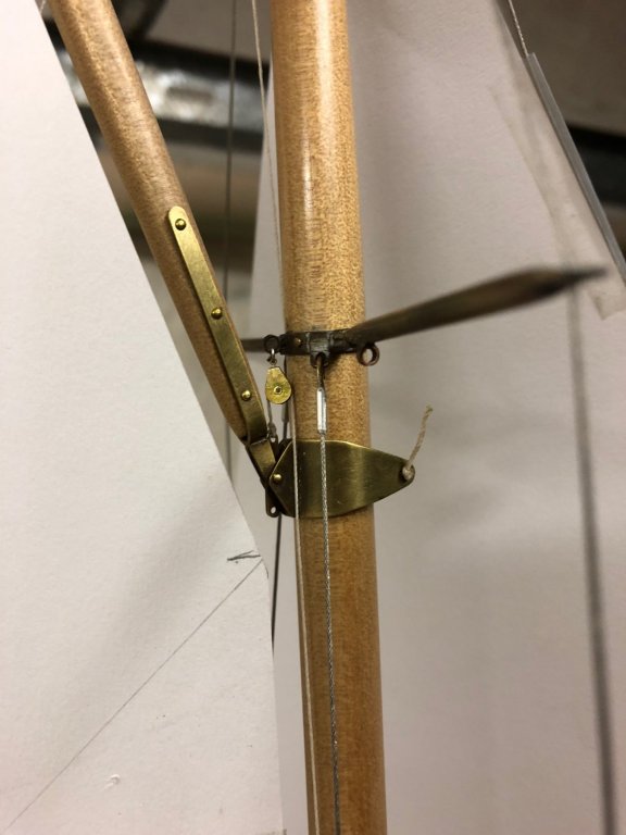

Peak halyard setup, gaff bridle & the sliding thing. For this size of boat a 1:1 peak halyard is fine. The running backstays here are temporarily done as thread (Guttermans top stitch), but I think I'll make the main part in wire with the tackles in rope.

gaff bridle is swaged:

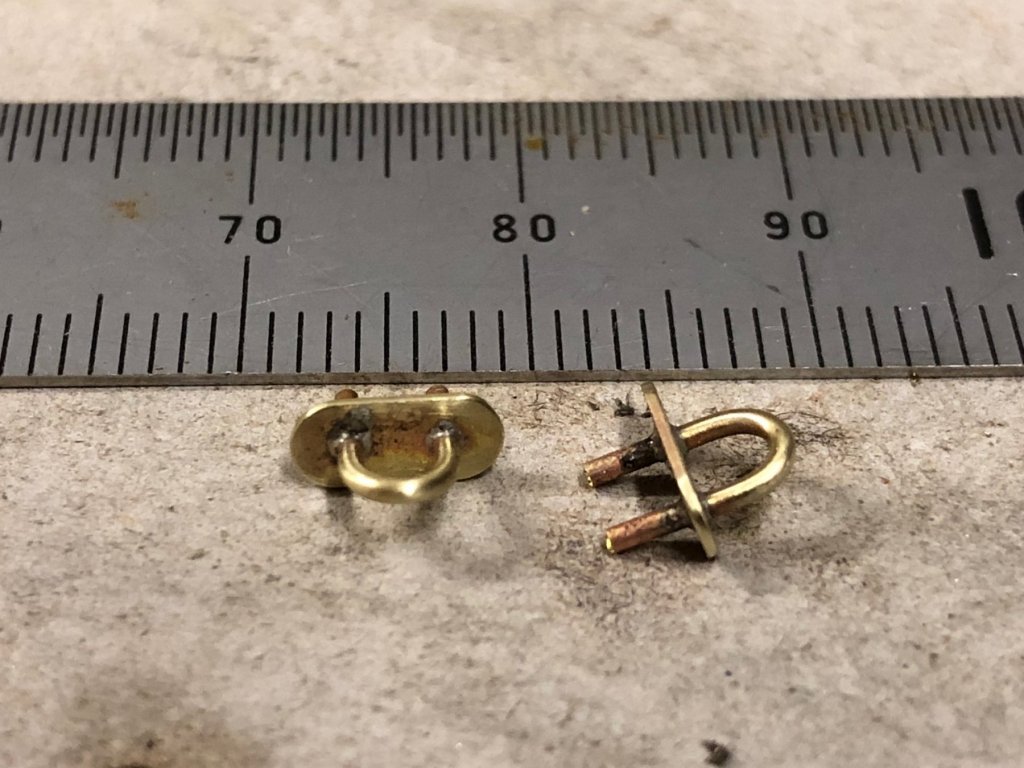
Plus some pad eyes that will be mounted on the quarters, they would take blocks for the spinnaker brace & sheets, still a bit of cleaning up to do. The tails below the pads are to increase the glued strength.
-
Hi Michael,
the result on the vents is very good, & I've learned something new from this.
On the companionway top colour: I feel that having a different colour to the top (from the sides colour) lowers the apparent height of the overall structure, which in most cases looks better on a boat as it elongates the overall lines. I also feel that a paler colour makes it look a bit wider than with a darker colour, so again I feel that it looks better.
Mark
- aviaamator, PeteB, Piet and 3 others
-
6
-
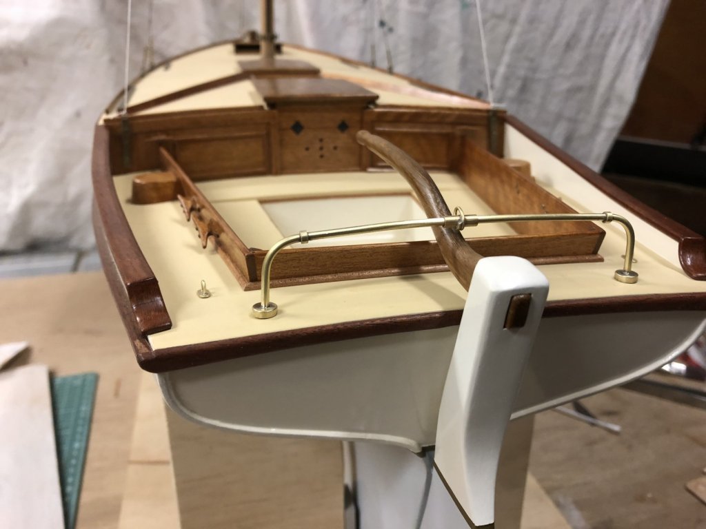
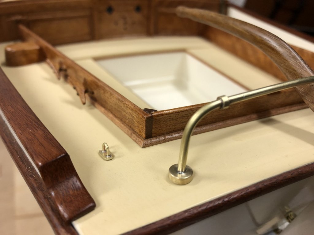
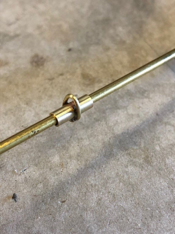
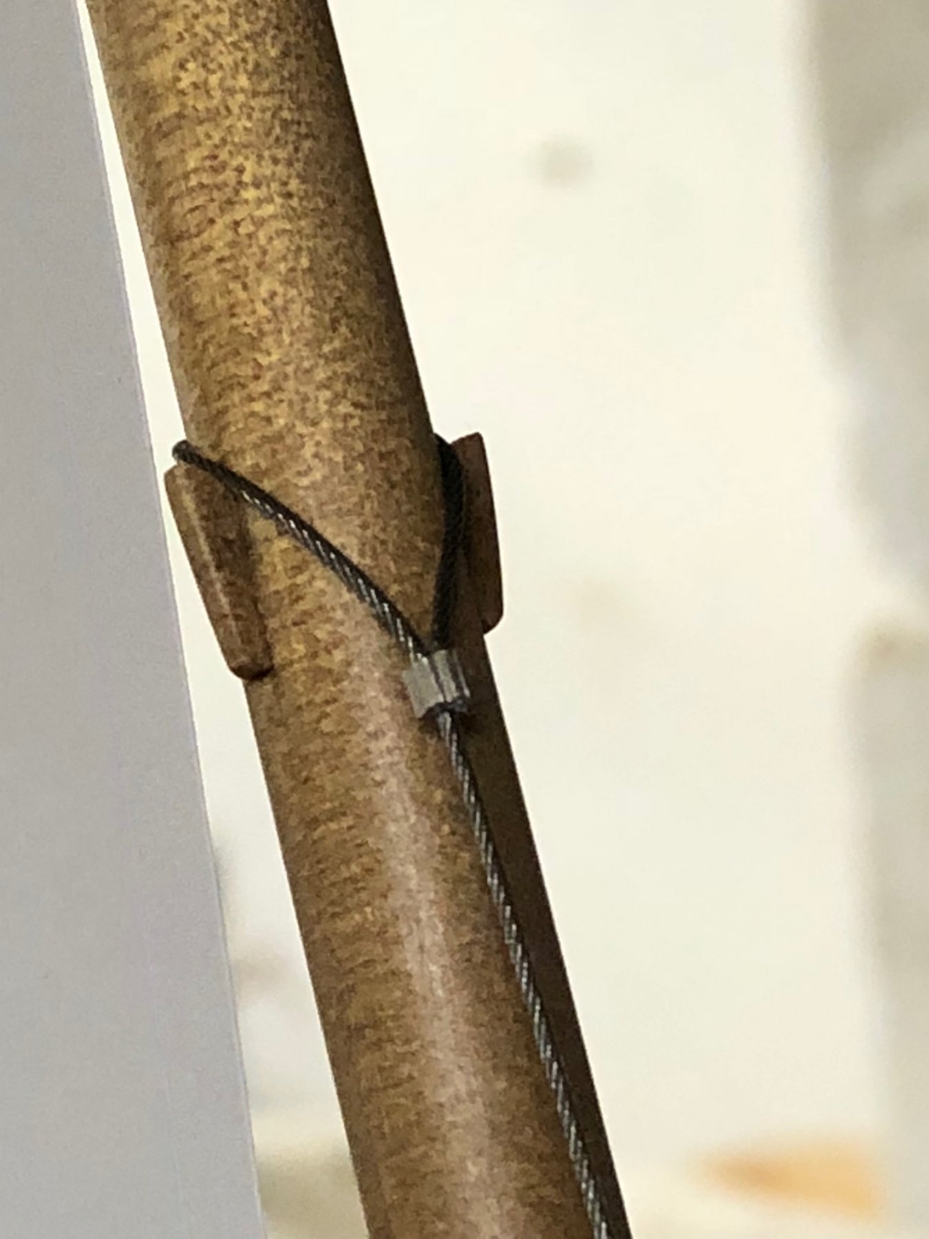
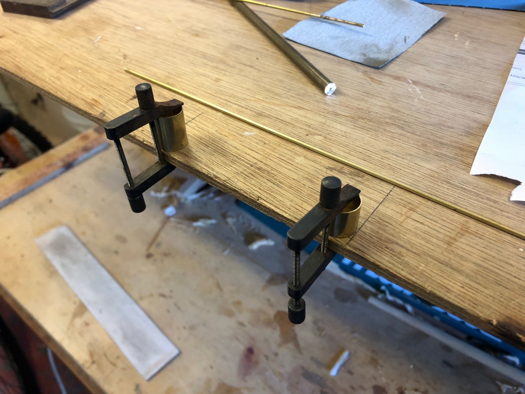
I made the traveller rail, starting with the small parts because they needed to be on the bar when it was fabricated due to the bends.
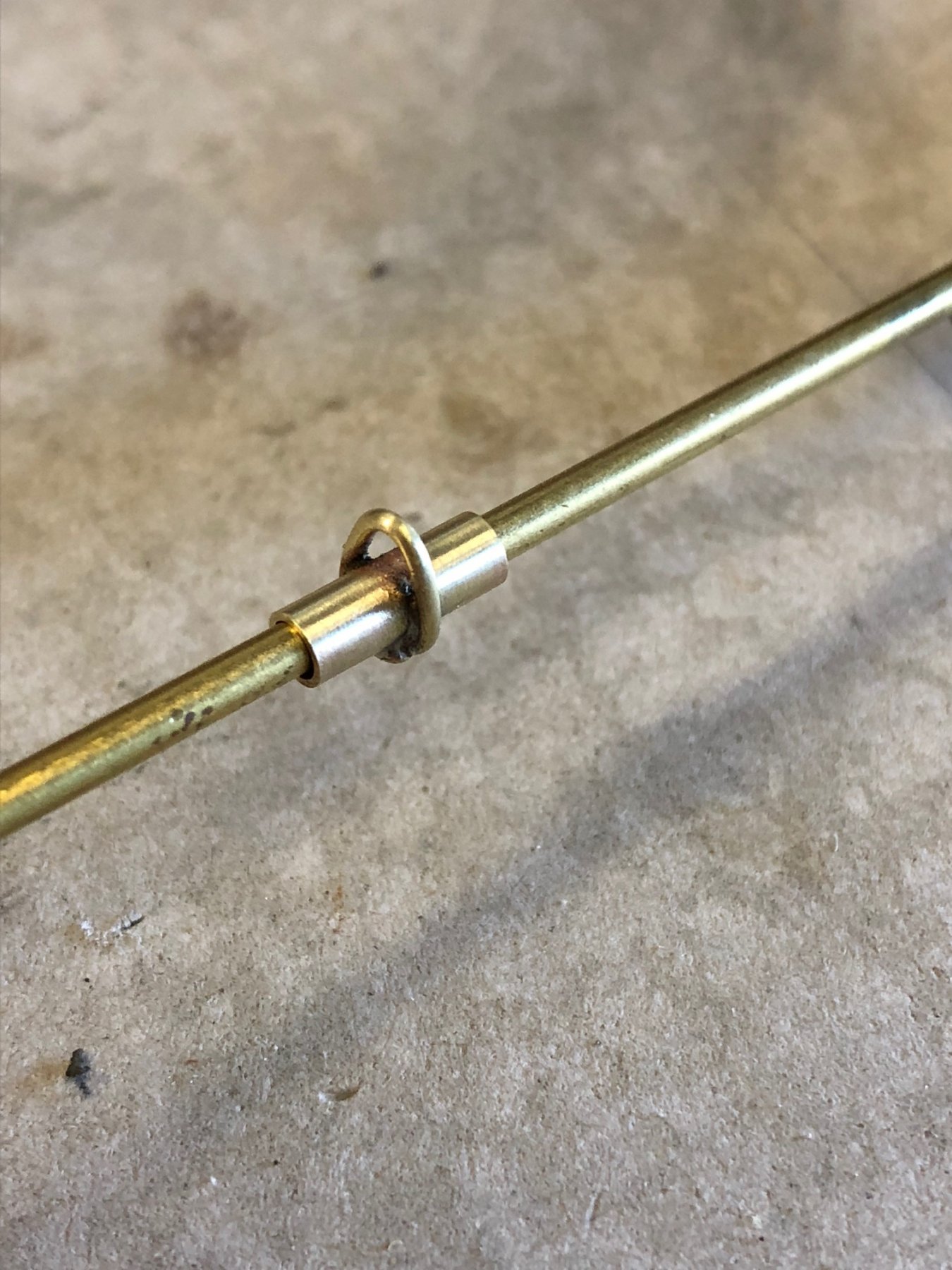
Below is the sliding piece that the main sheet connects to - tube with wire bent & soldered. As a form for bending I held a thinner piece of wire next to the tube to wrap the wire around both to get the shape.
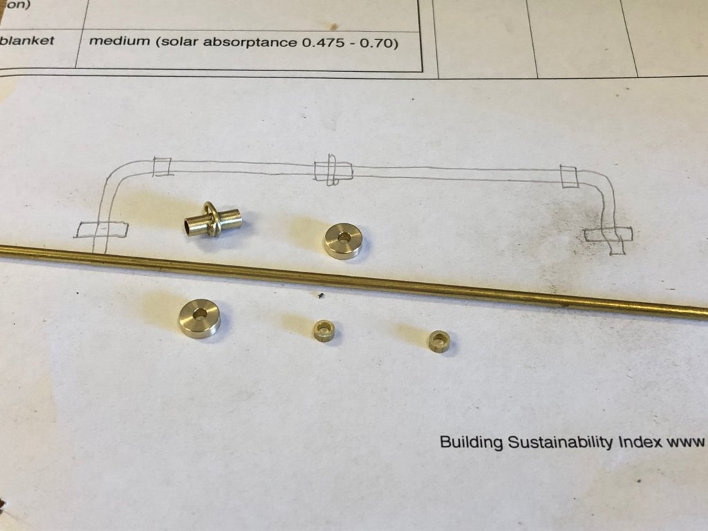
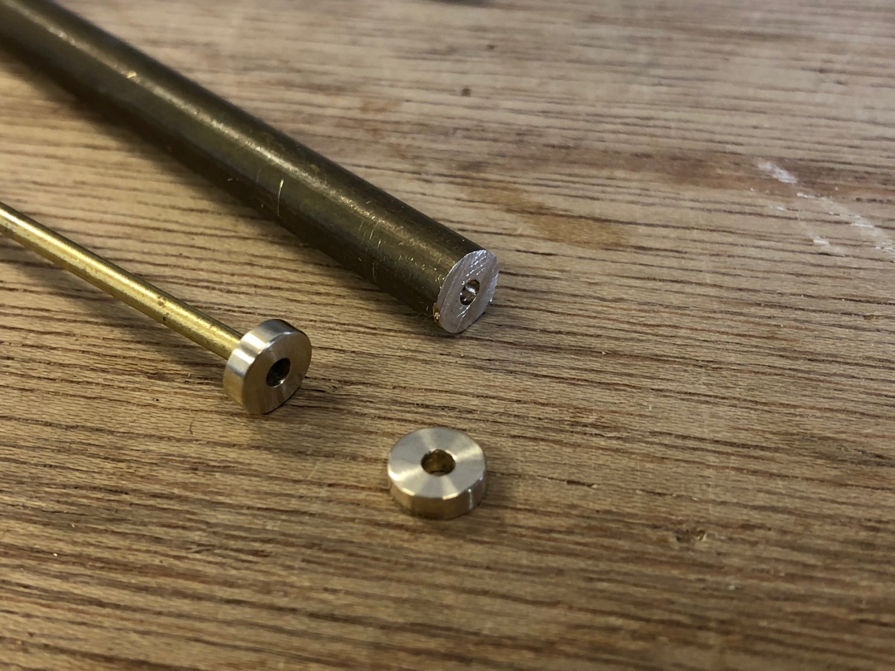
Below are the flanges that sit on the deck - 1/4" rod drilled down the centre & cut off. The thin rod was made to fit the hole tightly by some end tapping, to help in cleaning them up.

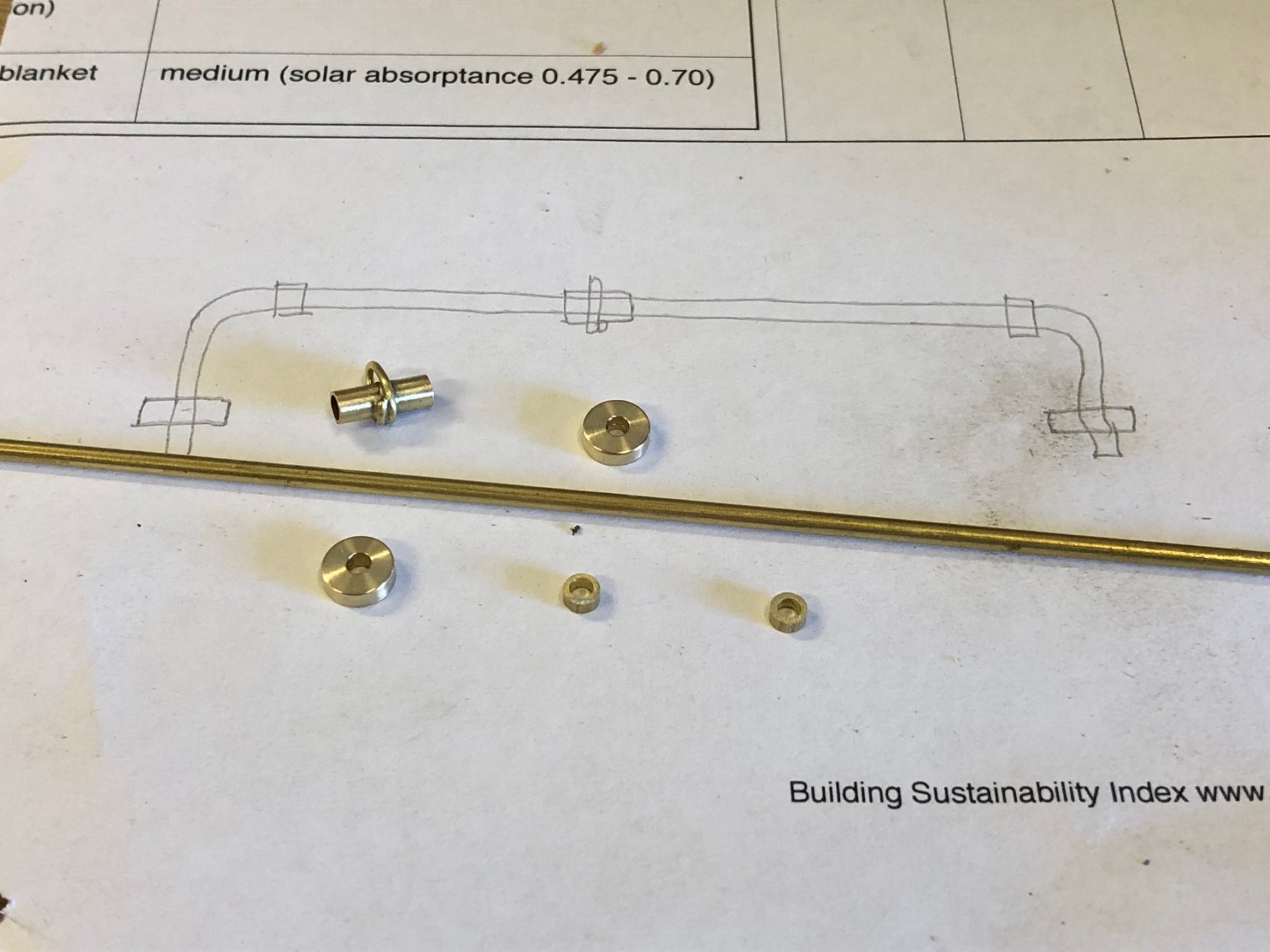
All the small pieces plus a sketch:
The bending jig for the bar:

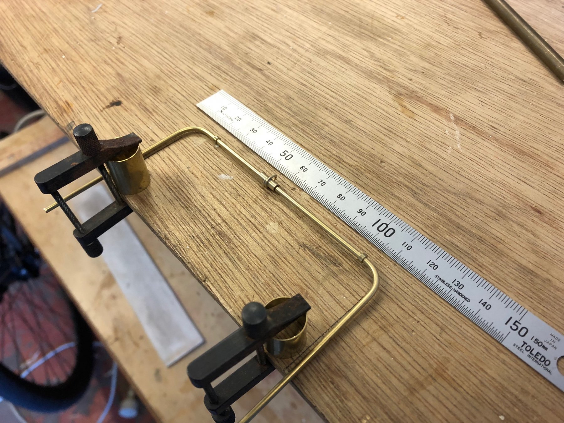
The small pieces were soldered on, & then the rod bent:

Then feet soldered on & the piece has been dry fitted. Not glued until I'm sure the deck doesn't need painting again. I put a gentle curve into the top bar, it looks nice & it seems that I didn't quite get enough clearance to the tiller - a bit of tiller reshaping helped also. I find that things tend to look better on boats if there are gently curves & slight angles, even if you think it should be square.

-
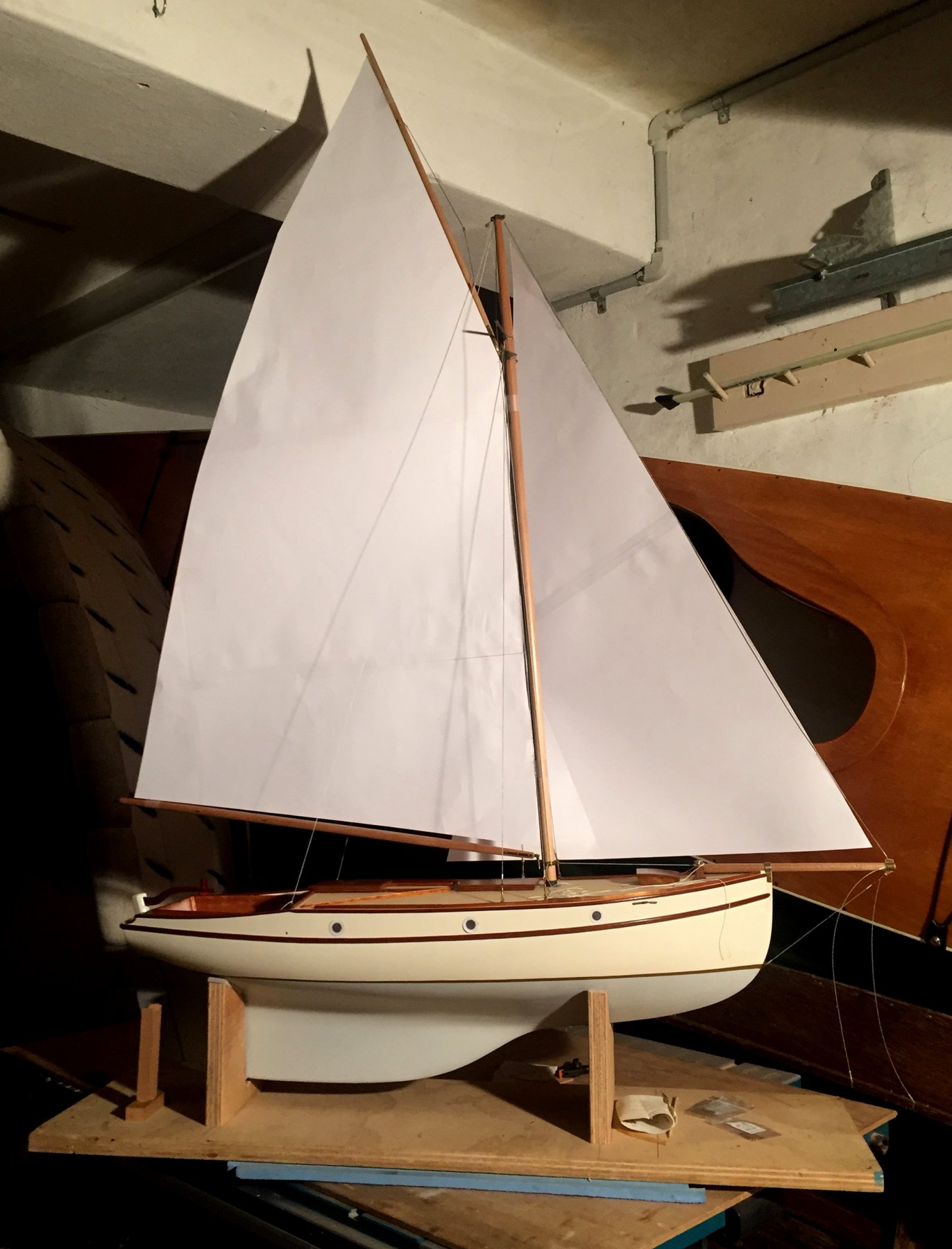
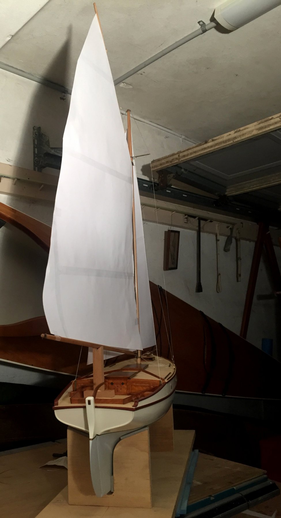
thanks all,
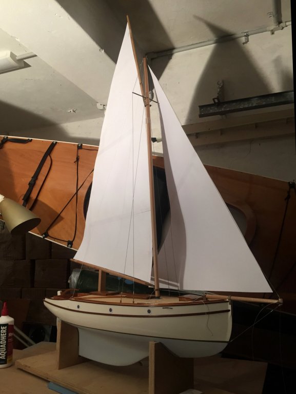
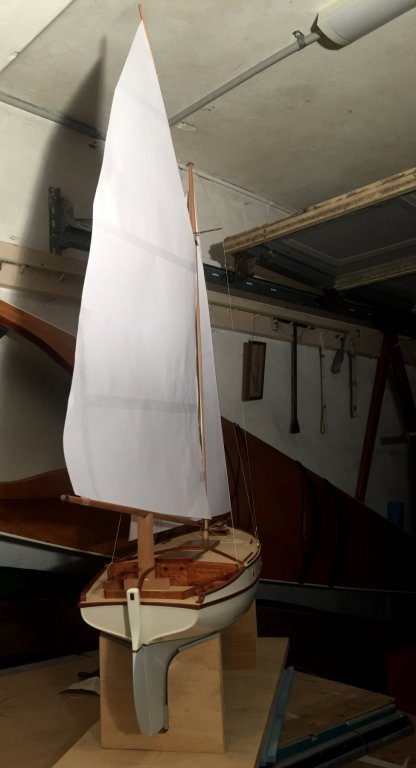
having the spars made I wasn't really confident that they looked right, I had difficulty seeing if the sizes looked about right or not, so I made some paper sails. It was a lot of fun & it also confirmed that the sail & spar sizes are quite good. To my eye the sails look just slightly conservative in area, but I would prefer that than if they looked a little oversized - this boats look chunky but I believe it would be lightly built & lightly ballasted. The headsail is intended to be a #2 & is still a little too large, probably move the clew forwards by 15 or 20mm & up about 10mm.
I'm starting to think whether it's better for the sails to be set to appear as if they have wind, or just hang.....
I'll post some photos of the rigging details shortly,
Mark

-
the split Dorade vents are very interesting, never seen that before
- popeye the sailor, mtaylor and Piet
-
3
-
Hi Michael, I hope this signifies your plans to restart this model.
I'm not so keen on the port side belaying because with water & load it might lock up. I don't mind the starboard one because, despite the mess, it will release easily.
Mark
- mtaylor, popeye the sailor and Piet
-
3
-
Hi Dick,
there might need to be some extra strengthening, but I think you are underestimating the strength of the planks & the way they would transfer loads from forwards to the whole hull.
Mark
- Louie da fly and mtaylor
-
2
-
-
thanks, & on consideration Michael I have to agree with you that visually the heads are too bulbous to get away with. For this model there's a number of things that are simplified technically but I'll have a look at this one & see what I can do. I bought some packs of brass miniature rivets & I like them so much they are appearing all over the place.
Mark
- michael mott, Jack12477, mtaylor and 2 others
-
5
-
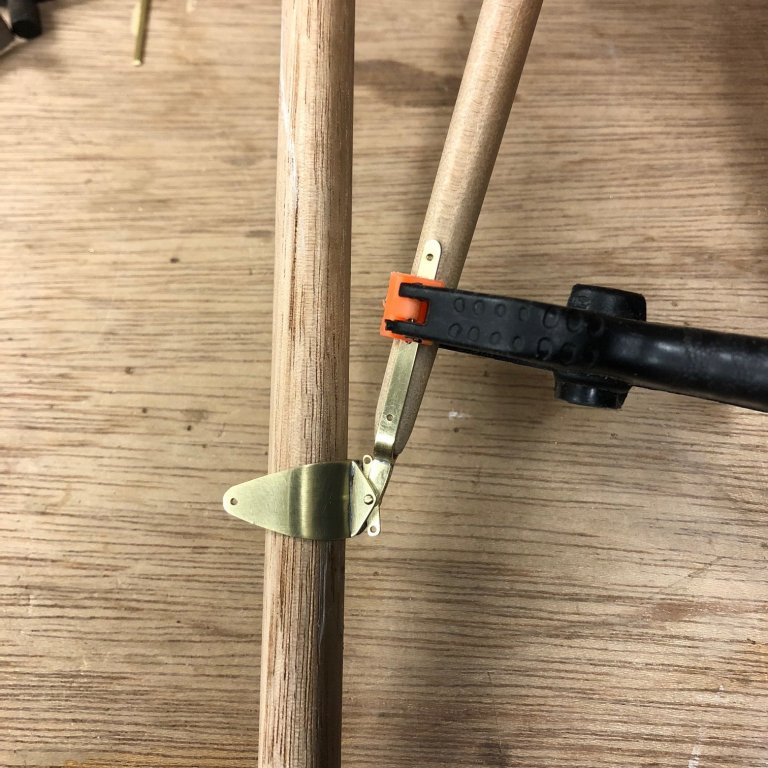
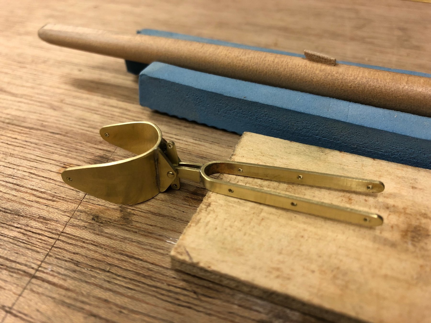
I've made the gaff jaws & gaff spar, but not done the final finishing & assembly yet. The jaws are what I am guessing would have been modern at the time of the yacht design, the mid 1960's. The part that would once have been a timber jaws piece is here a curved piece of metal, probably 6mm aluminium sheet or similar with cleats welded to the aft face, & the mast face clad in leather - which I probably won't try to replicate to scale.

This photo shows it approximately in its working angle - mocked up with a scrape dowel to replace the mast. The gaff angle in Australia seems to have been usually a high peak & the gaff spar length was usually almost as long as the boom. The angle means that the resolution of the parts is a bit tighter to fit in.
- John Allen, druxey, cog and 9 others
-
12
-
-
-
HI Steven
I have one comment & one question:
The spar wouldn't be particularly heavy but the sail would be very heavy, but considering the ready labour on board I reckon they'd be ok about a 1:1 halyard with half a dozen hefty Mediterranean types. There's also the mechanical advantage you get by 'sweating' the halyard, where you lock the tail of the halyard (usually around a cleat) & then above the locked point you pull the halyard horizontally away from the mast (it has a leverage action) - which pulls the halyard up a little bit - & then you quickly take up that slack on the downhaul part, & it inches upwards. Sorry if that's not clear.
How would a double sheave in the mast actually work to get greater than 1:1?
Mark
-
Bravo!
And thank you for patiently showing the methods used Michael,
Mark
- thibaultron, Jack12477, druxey and 4 others
-
7
-
I actually like the slight wobbles in the beam shelf, it looks ... old


Deben 5-tonner by vaddoc - FINISHED - Scale 1:10 - a Whisstock yard design
in - Build logs for subjects built 1901 - Present Day
Posted
well done Vaddoc, looks excellent