


Mark Pearse
-
Posts
706 -
Joined
-
Last visited
Content Type
Profiles
Forums
Gallery
Events
Posts posted by Mark Pearse
-
-
We changed the rig on our boat, partly to lower the CoE. Without calculating it I would guess it was lowered between 5 & 10%, & the difference was noticeable. 30% higher would be a large difference, & if my geometry/physics is good, the same force higher up would have more effect on a hull because of it's distance from the pivot point.
What are your thoughts on the role of the sails on these vessels - were they a pleasant respite from the oars or the preferred way of getting around?
-
-
Very interesting. Also noted is the quite large lateen sails on hulls that don't look to have much righting moment - or even freeboard - & the wind isn't light (black & white photos at the start).
On the rig balance question, I would have thought it's adjustable by changing the spar angle. More horizontal & there is more sail forward, more vertical & the sail is further aft. It would mean multiple sheeting positions so the sail could set well at a range of spar angles, perhaps a line of cleats or pegs along the rail.
-
thanks Steven. Have you seen this video of a replica longship at sea?
No doubt there are differences, but the hull righting moments might be similar to your craft. The incredible work done in Denmark & Norway on these craft have shown we previously greatly underestimated their abilities, & I might add the hulls seem much stiffer to heel than I would have guessed. A low square sail would be somewhat comparable to low triangular sails. Hope it helps.
all the best,
Mark
- davyboy, GrantGoodale, mtaylor and 2 others
-
 5
5
-
Hi Steven
the setup you've drawn would allow disassembly - the fixing block could be removed by a hefty thwack from the side. I am guessing that with the loads & movement of the boat, the difficulty is having a mast step that is both strong & also reliably easy to take down.
-
Frank, thanks for the enjoyable & informative posts - a great model to watch come together.
That's a really thin boom for the length, but obviously it works
Mark
- cog, Canute, popeye the sailor and 2 others
-
5
-
-
2 hours ago, Louie da fly said:
the downward force of the halyard would cause a powerful moment (turning force) to make the cap piece pivot around its attachment to the mast
Hi Steven, yes you'd probably be correct on that....but perhaps the mast rotating isn't a problem - if the force stays in the same direction as the hook it would reduce twist loading on the mast.
Could the shaped end be to help the lateen spar clear the mast as they go about?
-
Hi Steven
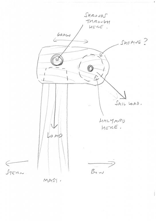
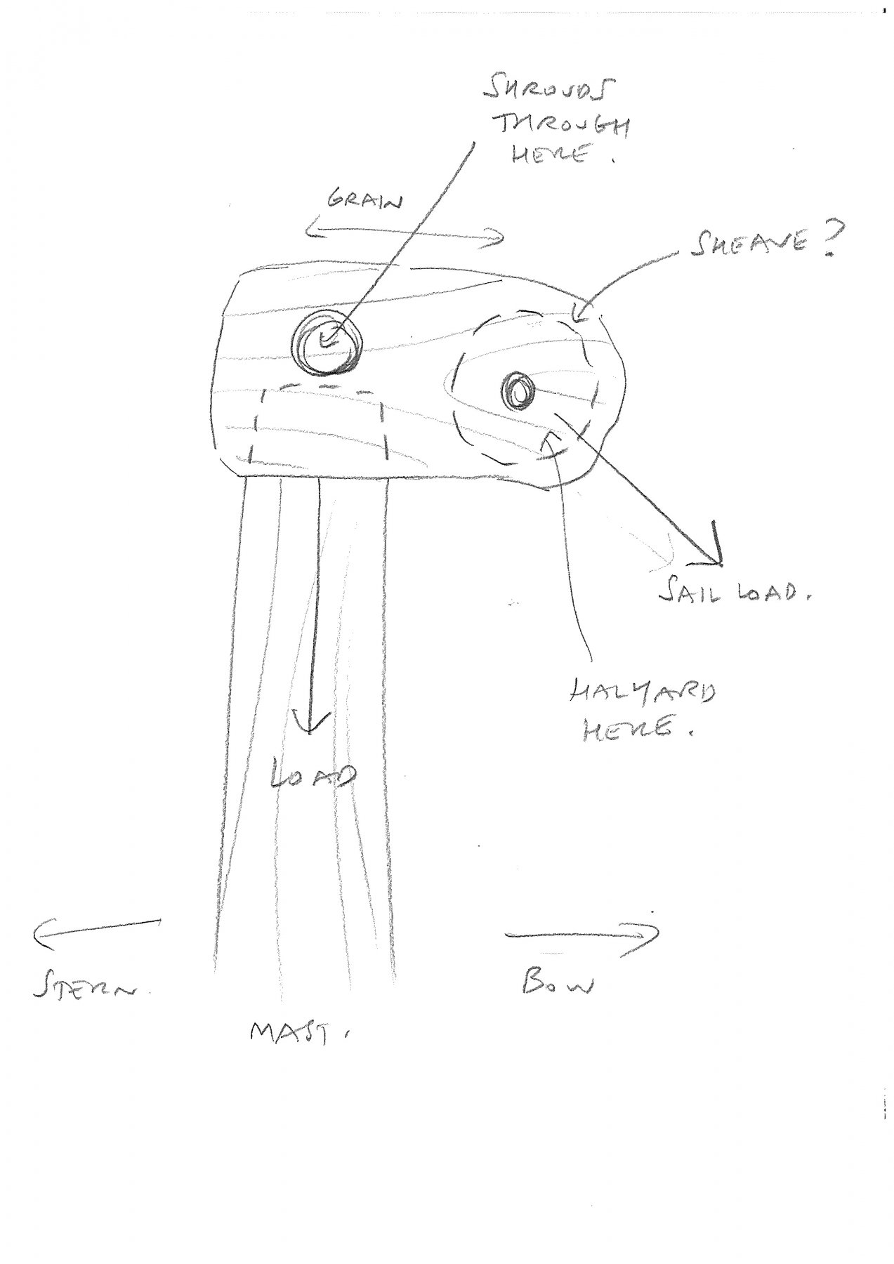
an interesting & difficult problem. Ideally you would put the shrouds & halyards converging at the same point, we can do that now because of our metalwork. If you take away that technology then bringing all these lines together to one point is much more difficult. Unpicking the reasoning behind that I think is the key.
I think that you are correct to assume the hockey stick end is the halyard: the shroud loads will be balanced by the mast & should connect directly to the mast, or in line with it. I feel the mast cap piece has to be a second piece of timber, & probably some sort of tough, strong timber. A good choice of timber for a mast wouldn't be a good choice for the cap timber. The sketch below might work, the grain is at 90º to the mast & it held in place by the shrouds load, & mast housed into the cap. The closer boat in the Homilies picture has a line that might indicate a separate piece of timber, & it looks to show the shrouds going into a hole above the top of the mast. The shrouds could be fixed to the mast by wrapping around the top or back of the cap a couple of times & then back down the other side, so the shrouds are continuous.
It's hard to say how the halyards are connected, but maybe it was just a loop of metal & the halyard ran through it. Alternatively, could it have had a single sheave? The sheave probably in some really tough timber & lubricated with fat.
-
Hello Maury
those lines do look quick, the run aft underwater is very clean. Was the need for speed something to do with the economics of the oyster trade?
Is there any similarity with Slocum's Spray? (albeit longer & larger....)
Mark
- mtaylor, BETAQDAVE, aviaamator and 1 other
-
4
-
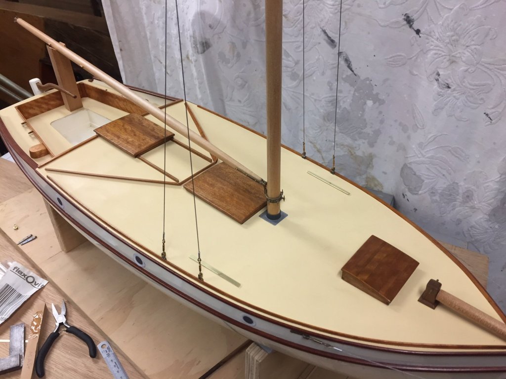
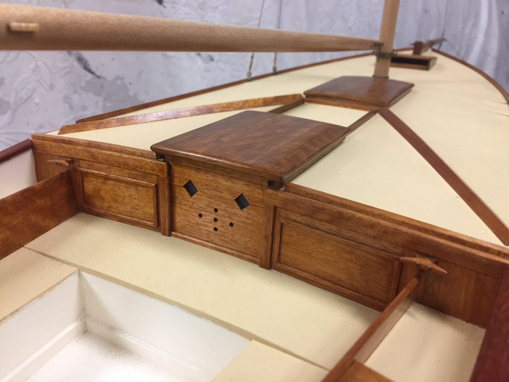
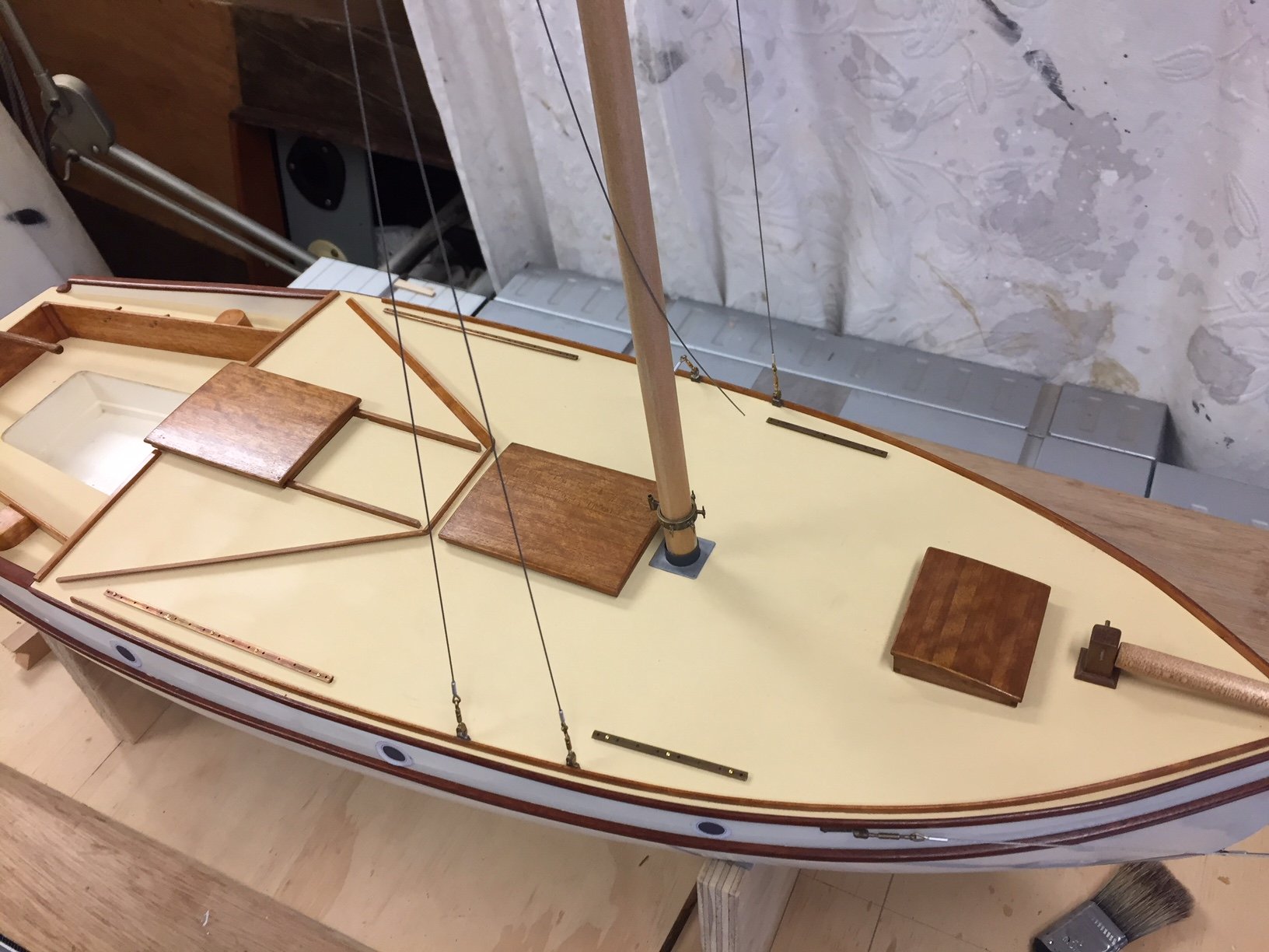
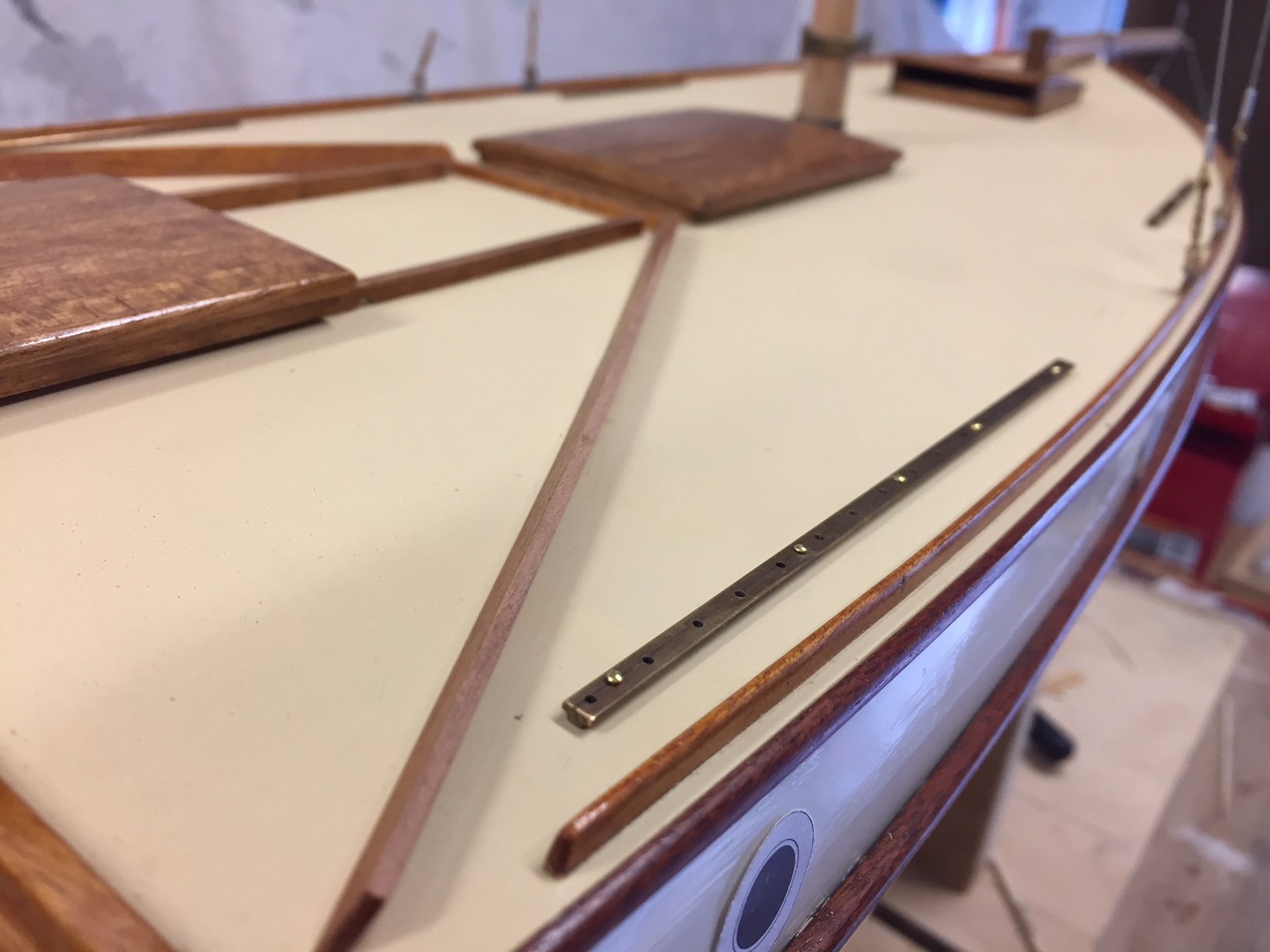
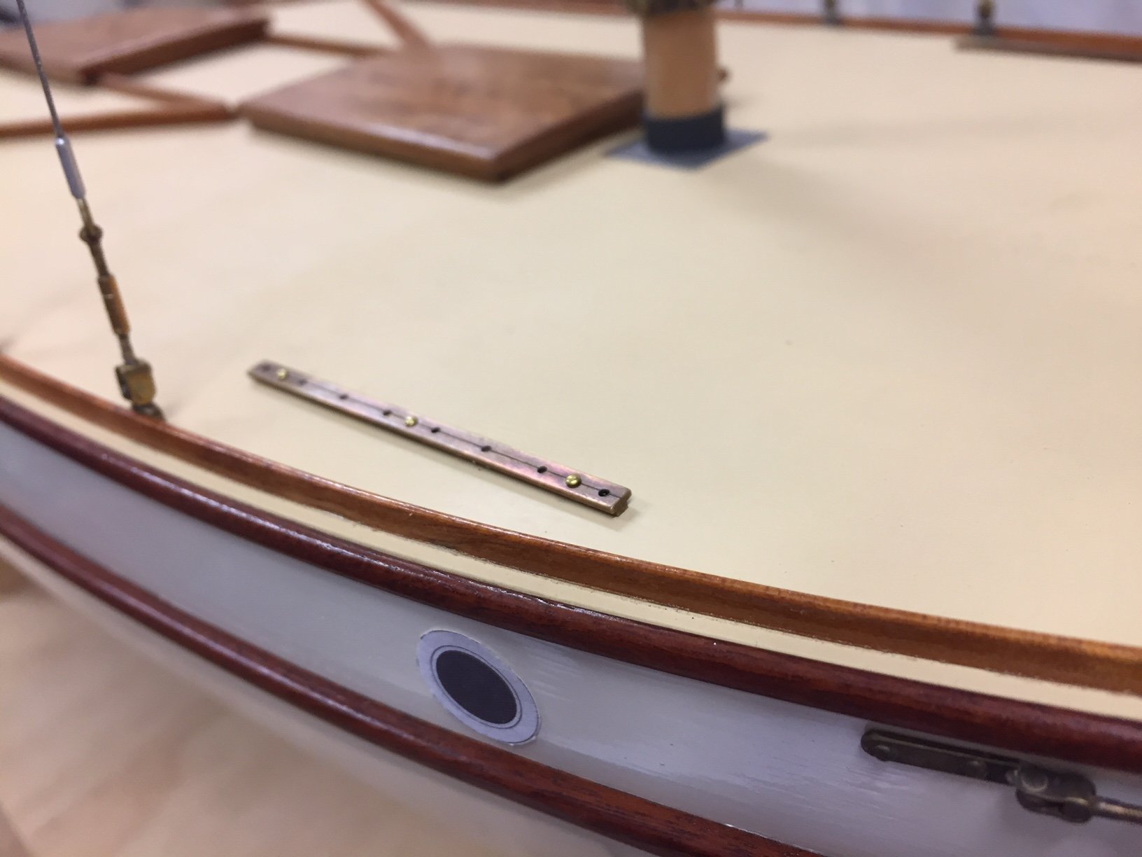
The sail tracks are now completed. As they were left from the last posting the plain surface looked a bit blank, so I got some decent quality 1mm bits & drilled some part-depth holes to replicate the car locating points down the tracks, & also scribed a centreline - to help locate the drill bit plus I thought it would look right for some reason that I can't explain. I drilled some through holes to peg the tracks down & they are shown below pegged in their position but not glued down, the deck might need some more paint & there's no guarantee the colour will still match, or indeed even be usable so another full coat of deck paint is a definite maybe. The track holes didn't look very good or convincing, so I put a dot of darkening solution in each plus in the scribed centreline. I'm happy with the result, & I must say it's much faster to drill brass using a good bit than some piece of cheap rubbish that I bought in sets....
A longer track for overlapping headsails, plus a short one forwards for #3 & #4 headsails.
thanks all,
Mark


-
thanks,
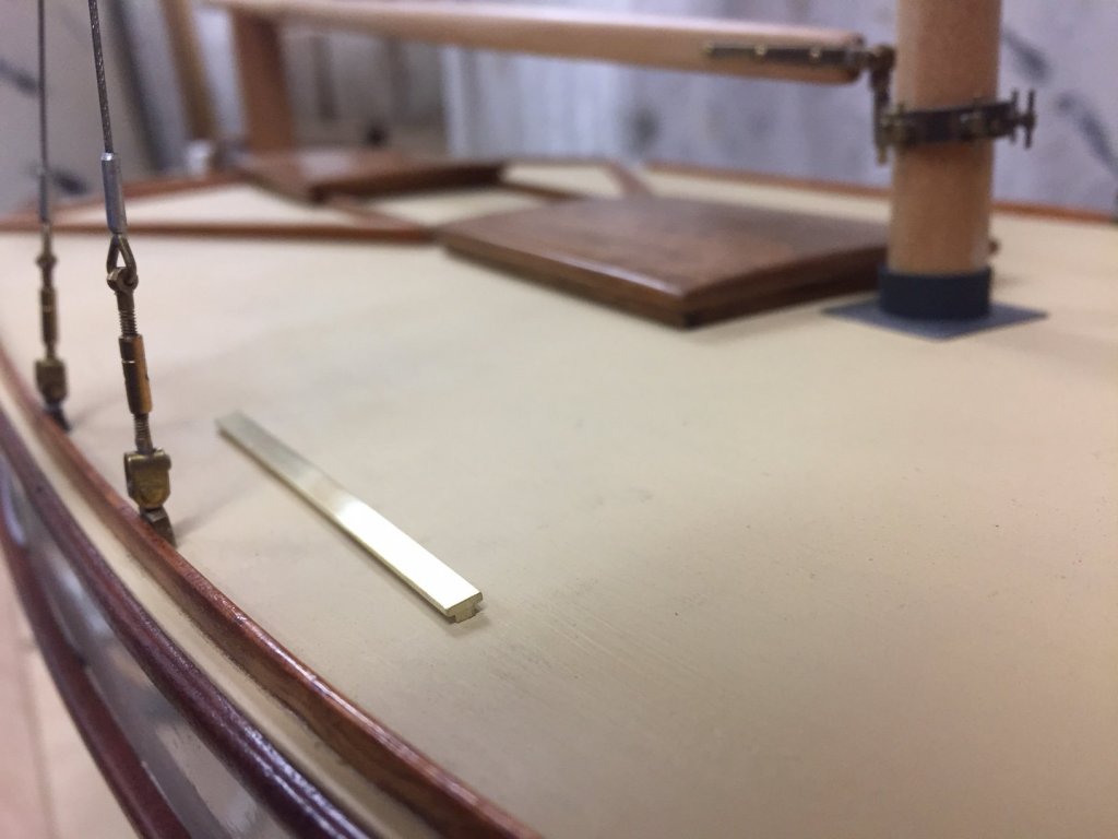
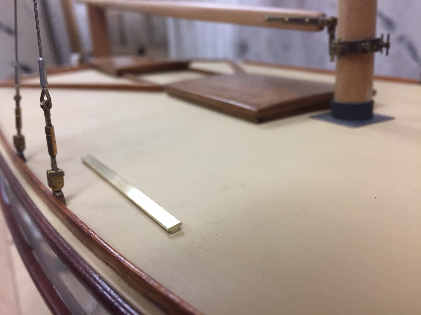
I made the forward sail tracks tonight & they were surprisingly easy - a classic T track from a wider piece of brass soldered on top of a narrower piece, in this case the narrower is from two very small squares - as that's what I had & the size is good. Full size for the track is about the standard size 32mm or I guess that's 1 1/4" imperial. There will be longer tracks further aft on the deck, a #1 headsail on this boat would probably have the clew about 2' or 600mm from the edge of the raised deck.
I'd like to drill some shallow holes along to give some texture & replicate the car stop holes, but it seems that the drill bits I have get blunt very quickly. I'll see if I can get a tungsten tip one from the local hardware store, anywhere from 0.5mm to 0.8mm or so would do, about 6-10mm diameter full size.
In the photos they tracks are in the approx position, just sitting there. I'll colour them also.
-
Hi Vaddoc
more nice work.
Could you explain a bit about the comment below? thanks
8 hours ago, vaddoc said:I ll wait for a few weeks for the oil to polymerise before I varnish
Also, you might already know - but esp on a yacht it's important that the waterline isn't painted dead horizontal, whether just a change in colour or a boot top line. A shipwright explained it: lowest point aft of the centre of the hull about 40%/60% of the hull length, raising towards the bow & stern, & finishing higher at the bow. If it's a boot top line it should also get a bit thicker in the same way. For a yacht that's 30 foot long it's around 2 to 3" difference between the lowest & highest point. You don't actually notice it, but I'm told that you notice it if you don't do it, it appears to curve downwards towards each end. Just when you thought it was complex enough....
maybe the advice is wrong though,
-
thanks,
I made the forward sail tracks tonight & they were surprisingly easy - a classic T track from a wider piece of brass soldered on top of a narrower piece, in this case the narrower is from two very small squares - as that's what I had & the size is good. Full size for the track is about the standard size 32mm or I guess that's 1 1/4" imperial. There will be longer tracks further aft on the deck, a #1 headsail on this boat would probably have the clew about 2' or 600mm from the edge of the raised deck.
I'd like to drill some shallow holes along to give some texture & replicate the car stop holes, but it seems that the drill bits I have get blunt very quickly. I'll see if I can get a tungsten tip one from the local hardware store, anywhere from 0.5mm to 0.8mm or so would do, about 6-10mm diameter full size.
In the photos they tracks are in the approx position, just sitting there. I'll colour them also.
- KORTES, kees de mol, G.L. and 6 others
-
9
-
I haven't been working enough on the model yacht, but some recent progress:
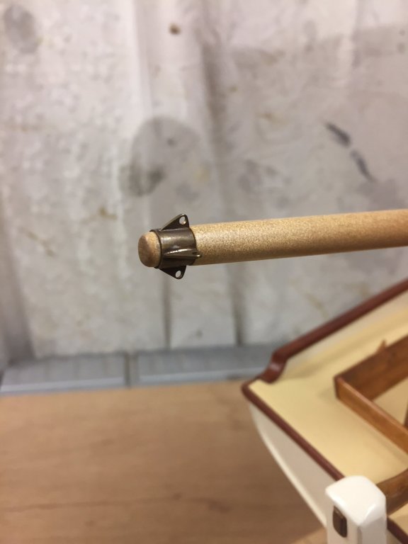
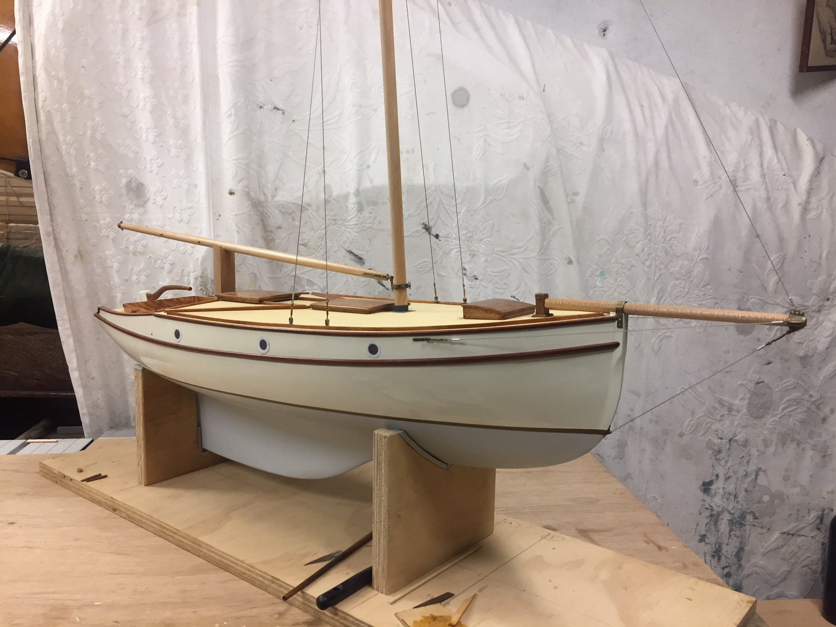
the boom is done with thumb cleats each side & the gooseneck fitted, plus the fitting on the cap iron on the end of the boom is done also. The boom really sets the hull lines off.

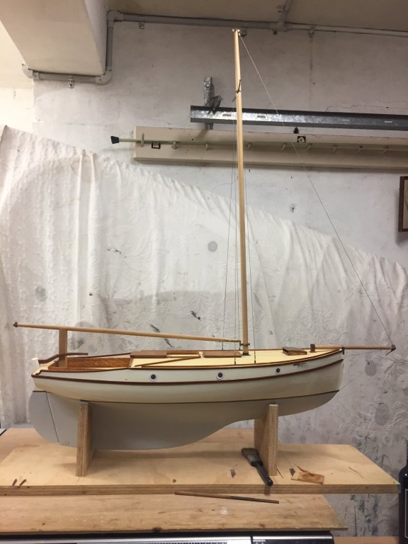
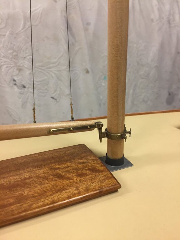
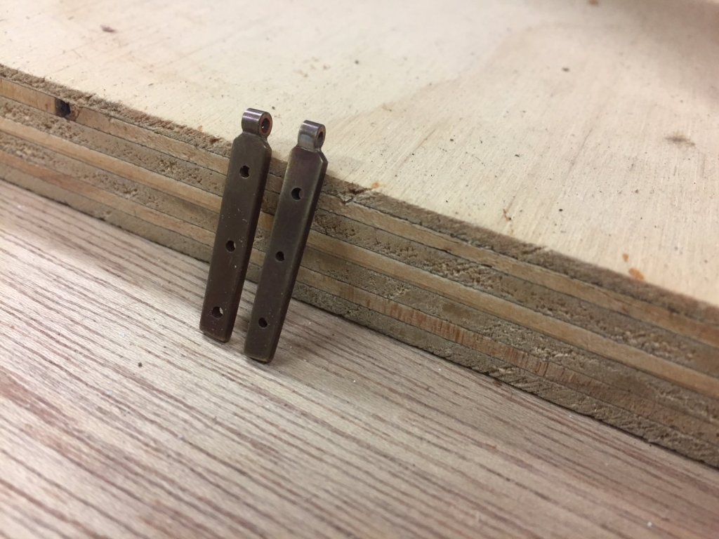
Some other minor bits: the running backstay chainplates are done. They will be mounted on the sides at the step in the deck.
I refined the shape of the cutwaters, they now taper down in height as they go further aft. (they are angled boards on the deck).
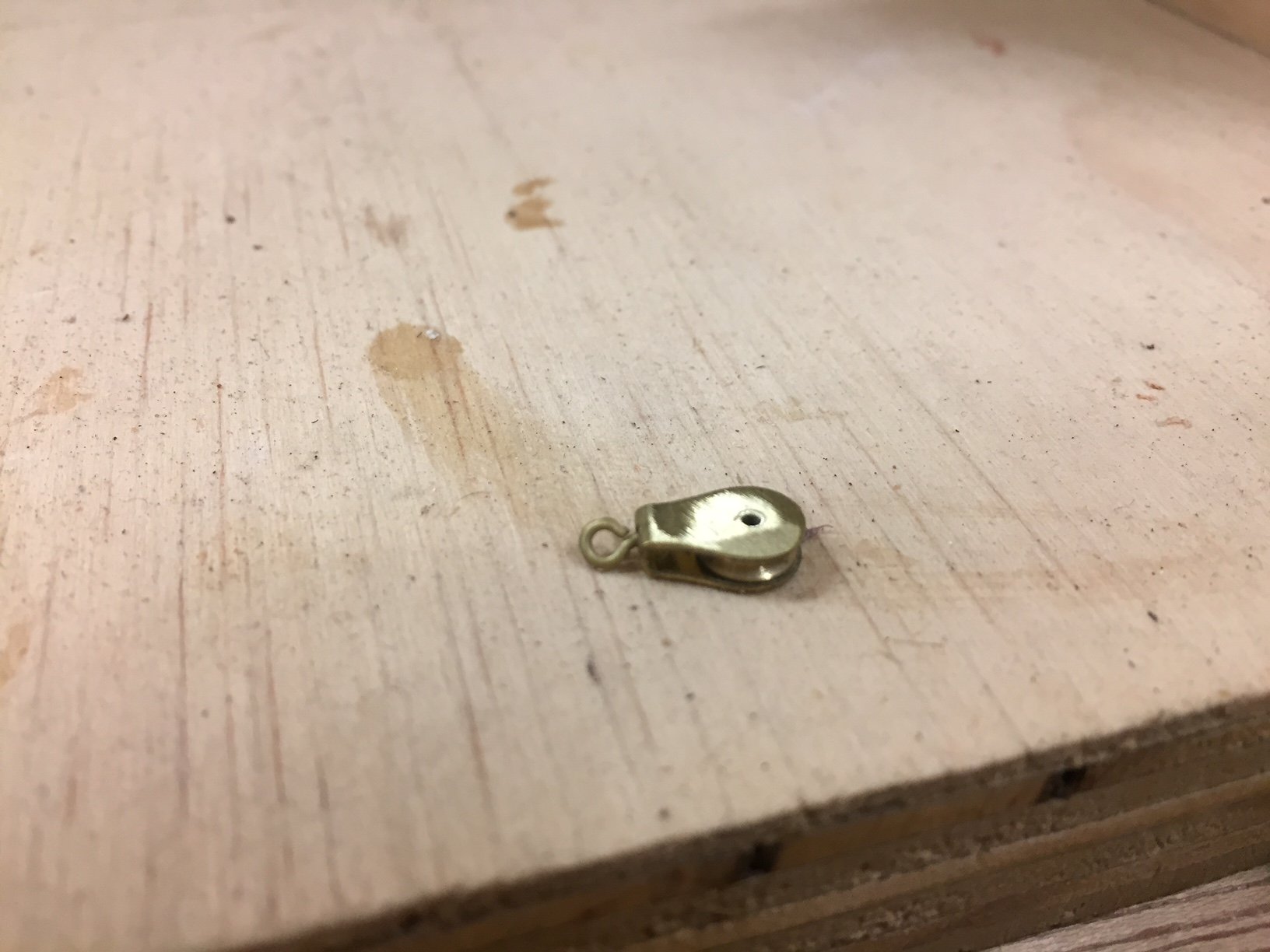
And I've been looking at some fairly cheap brass blocks, as below, & wondering how they can be improved.... I sanded off the knurled edges of the riveted axle (which wouldn't look great on a scale model), & good news is that the block didn't fall apart .... so ... the plan is to glue thin pieces of timber each side of the block to replicate tufnol, or timber. If I can sand the sides very flat I might be able to turn them into double blocks by gluing or soldering two side-by-side.

thanks all ,
-
Hi John
all the best, I look forward to seeing the model develop.
Mark
- popeye the sailor, Piet and mtaylor
-
3
-
-
-
thanks Jack, that's very interesting. It's hard to imagine, but does the tiller kick a lot? A metal tiller with the unforgiving nature of ice...
Also, it's fascinating to see that the sail shapes are so similar to the boats of the same period & yet the demands would be more different than it seemed at first glance - at the incredible speeds they go the apparent wind is almost always going to be well forward & strong to very strong, maybe even 50 or 60+ knots apparent. You'd not get that very often on the water & yet the sails & spars look like you could just drop them straight into a boat....They must be a blast to sail on.
- mtaylor, CaptainSteve, cog and 2 others
-
5
-
Hi Jack
I had to resolder some joints that had broken in a difficult position & managed to control the excess heat by using small pieces of wet rag wrapped around the bits I wanted to protect, & put the solid head on the flame torch.
On the unusual main sheet system, I have some thoughts on why it's set up that way. It's effectively a double ended main sheet, so that the boom adjustment has either speed of adjustment or power. If you want to pull the boom in quickly & there's not much load you use the aft sheet, then when the wind load comes on you would use the forward tackle at 6:1 or whatever it is. You'd have to keep an eye on where the sliding block sat & not let it get too far forward or back, maybe there's a way of locking off the boom & resetting the position of the sliding block during a long leg.
A question: on the actual ice yacht, what are the skids made from?
thanks, Mark
- popeye the sailor, Canute, Jack12477 and 1 other
-
4
-
-
Yes the deck would be a problem for pivoting - for lifting, if the mast was very heavy you could use a simple lever system below decks, & as it gets lifted - say each lever lifts the mast 20cm - you chock the mast to stop it falling back (or use ropes from above taking up the slack as it's lifted, the ropes going through the deck hole & tied off to some fixed strong point) & do it again. When the mast base clears the deck level you use the ropes to restrain it & do a controlled slide along the deck. It's starting to sound possible, but maybe that's too much optimistic imagination...
BTW, I have a small amount of mast lifting experience, one solid timber one on a 17' boat & it was manageable by myself but quite difficult - a mere toothpick compared to your vessel. We also lifted a a 9.5m timber mast with an electric crane, it was hollow - a wall thickness of 1" & a diameter of 140mm - so probably only 50% of volume solid timber, so quite light for the size & much much slimmer than your Dromon mast would likely have been. I reckon it would be possible to lift one of these by hand - but only with some sort of mechanical advantage.
-
-
I believe the mast step arrangement of a simple slot would easily be enough to hold the foot of a mast, provided the top of the mast is stayed. You mentioned that you doubted that the masts could be raised & lowered at sea - but I think it's possible in these craft (not because I know anything about the boats, I must add). To hold the base of a mast in place doesn't need to be complex, & I think that raising & lowering is possible because the boats are so long compared to the mast height.
I would guess that they would pivot the masts (not lift) because it would be easier, & rigging lines to do that job would be simpler than what would be required to lift the masts up. In terms of the mast step, if the rectangular slot was long enough so the end of the mast could rotate as the mast swings, then there would be no impediment to it rotating - but it might not be stable enough. Possibly they had timber blocks that sat in the slot either or both sides of the mast, wedged to hold it all tight. If you want to lower the mast you'd knock the wedges & blocks out & the mast step would then it can rotate in the slot. I would hazard a guess that when lowering there would be a point at which the base of the mast came out of the slot, at which point you'd need a heavy rope controlling the base of the mast because there would be a lot of load pushing it. You'd need to control it with that rope & maybe even allow it to move along to be shipped where you wanted it in the hull.


28' Ranger-type Yacht by Mark Pearse - FINISHED - 1:12
in - Build logs for subjects built 1901 - Present Day
Posted
I fitted the running backstays chainplates, after avoiding them for some time because two thin & shaped timber pieces were required, which were tricky to get accurate. But done now, as below. This will require a tackle system for the backstays so that the resultant loading on the chainplates is more or less vertical, rather than pulling them off - which would be the case if the backstays were 1:1. The angle between the backstay to the mast & the tail to the winch is such that if you bisect it (1:1 backstay), the angle would be pulling the chainplates aft by quite a lot. Likewise, they lean inboard to the same angle as the run of the backstays to the top of the mast.
before:
after:
I have also done a mast track for the mainsail. A yacht rigged in the mid-late 1960s would have had a track for the luff, which I replicated using an off the shelf brass C channel. It's oversized for tracks of the time, but doesn't look wrong & there seems to be only limited sizes available for the C section in brass.
The gap at the top to the spreaders is because the gaff throat would sit just above the top of the track when there was a reef in the main.
thanks,
Mark