
HOLIDAY DONATION DRIVE - SUPPORT MSW - DO YOUR PART TO KEEP THIS GREAT FORUM GOING! (89 donations so far out of 49,000 members - C'mon guys!)
×


usedtosail
-
Posts
2,414 -
Joined
-
Last visited
Content Type
Profiles
Forums
Gallery
Events
Everything posted by usedtosail
-
 Looks like an interesting little project. Of course you will put your spin on it, which is always fascinating. I'm glad you got the car past inspection.
- 171 replies
-
- 8
-

-
- krabbenkutter
- authentic models
- (and 1 more)
-
If you want to paint the metal eyebolts, put some primer on them first, which will keep the paint from flaking off. I use a metal primer called Bin that works well. I also soak the parts in white vinegar before priming or blackening them, which gets any oils off of them.
-
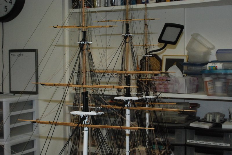
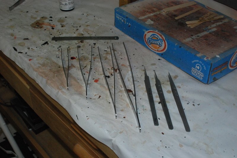
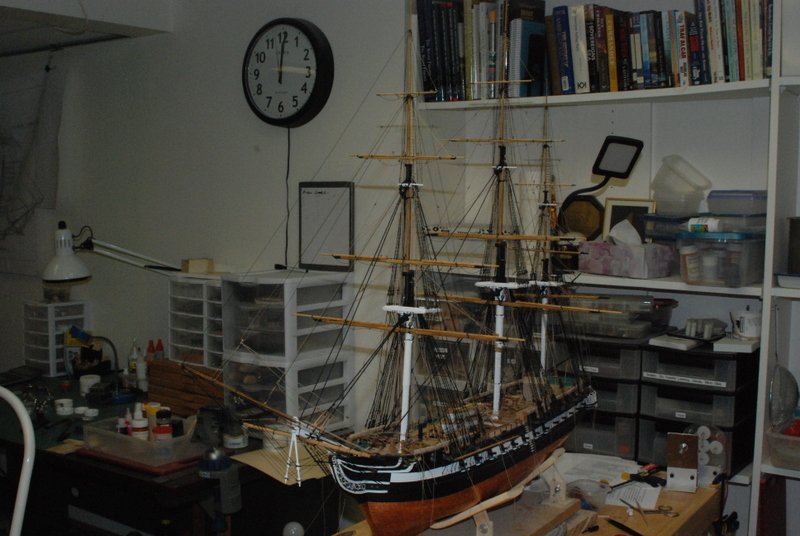
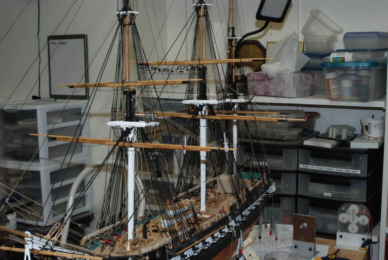
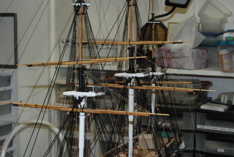
Thanks everyone. KMart - You are doing a great job and I know your Connie will come out great. I have found that taking my time and going back to fix things that I don't like has made a big difference in how it has turned out. Clay - thanks for your offer to share ideas on the case. I would love to see pictures of yours. I usually make a base with a full cover that I slip over the top, but this model is too big for that. I first thought about a hinged front, but even that I think will be too big, so now I am thinking of a removable front and top, with the other three sides screwed to the base. I have just started working up plans for that design, but I am open to other ideas too. I won't be starting the case until late September or so, after our planned move this summer. Dave - no worries. I know you are busy on yours and there is still a chance you will overtake me. I would be open to your suggestions on the case too. I now have all the yards attached and rigged, and I think lined up as best as they are going to get. I am very happy with how they came out. I have gone back and fixed a few of the rigged lines where they were not running true, and I think I have found all of those. Here the top gallant yards are fully rigged. And here are some close ups of the fore top gallant and topsail yards, with the buntlines and leech lines rigged. And here are the royal yards added, first during rigging then finished up. I have tied off all the lines to belaying pins and fixed the knots, but have not cut off the excess line yet, in case I need to do some final adjustments. I still have to make and add rope coils to most of the pins, which is going to take some time. As I mentioned before, getting to some of the pin rails is getting very difficult, but I ordered some larger tweezers from Amazon that help a lot. Here is what I bought. The four large ones to the left are not as useful as I thought they would be, as the tips are pretty blunt. I may try grinding the tips down to a point. The other three have been very useful, especially the one on the right. This is about 8 inches long and with it I can reach across the deck to any pin rail on the other side. It was very useful for tying the lines to the pins, and should be just as useful for setting the rope coils. I plan to next make and place rope coils on the pins rakes that are full, then add the brace lines to all the yards, the sheets and tacks for the lower fore and main yards, and the rest of the rope coils. After that, the davits and anchors will be added. I don't know if I will get to all that before we move, but that will be OK as I will pick this up again in the Fall.
- 1,350 replies
-
- 13
-
-
- constitution
- model shipways
- (and 1 more)
-
Jesse, those ratlines look so real. Seizing the ends to the shrouds to me is the real key here. I always have trouble with some of the ends coming undone if I just use a clove or a luggage hitch on them. Next time, I am going to use your technique for sure. Thank you. BTW, I used to think that tying the clove hitches was a lot of work, but I think if I counted the number of seizings I have had to do on the Constitution rigging, it would be a lot more than the number of clove hitches in the ratlines.
- 1,306 replies
-
- 7
-
-
- syren
- model shipways
- (and 1 more)
-
Mark, from experience, you will find those blocks that flew away when you are looking for something else on the floor. Dealing with those small blocks is challenging. I used 3/32" blocks for the Connie guns and am using them now in the upper running rigging. I was loosing a lot at first (which I think I have found most of since then), but was able to get a pretty good process down to stropping them. I just takes lots of practice.
-
Yep, that's how I adjusted the heights on my gun deck guns. I used a straight edge razor blade to make the cut in one push.
-
Thanks Jon. I do have a place in our new home to display her. Making a case for her is going to be quite a challenge, though. I have some ideas though. Just a quick note that the topGallant blocks for the lifts did stay in place when I installed the lifts through them and tightened them up, so all of the rigging for those yards is done, except for the buntlines, which I am working on now.
- 1,350 replies
-
- 2
-
-
- constitution
- model shipways
- (and 1 more)
-
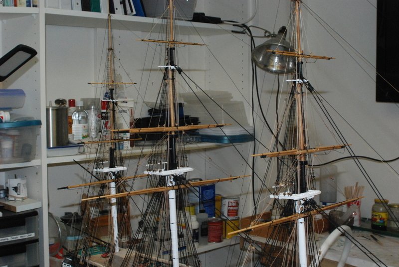
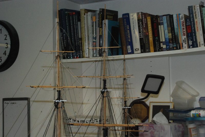
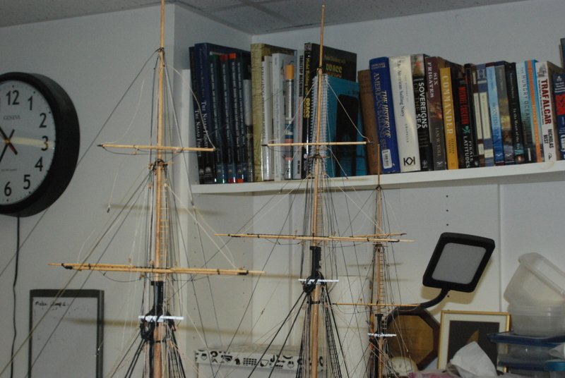
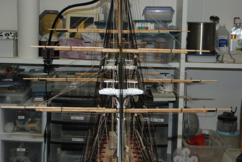
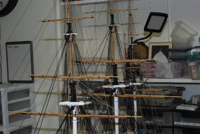
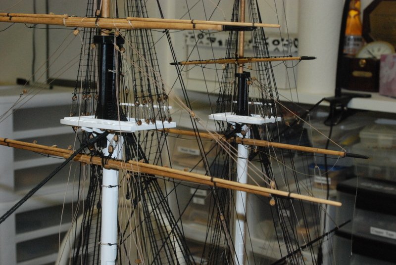
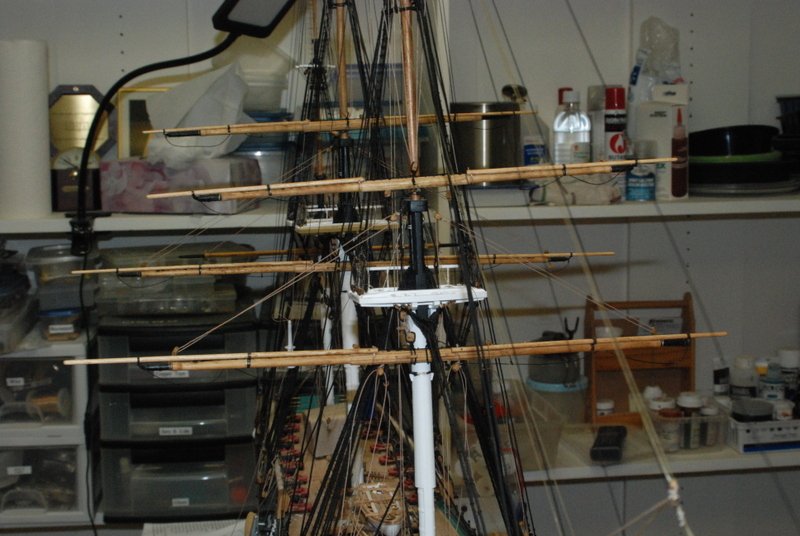
Thanks guys. Other pictures I found had some of the plastic models I built as a kid - mostly funny cars, but there was also the Visible Body, if you guys remember that, and a V8 engine model kit. It did bring back memories. Work has continued, mostly on rigging the topGallant yards. First a picture with just the lower and topsail yards, adjusted to my liking. Of course, with all the subsequent work they have come out of alignment somewhat, so I will wait until all the yards are installed before tweaking the lines to get them to all line up, if that will be possible. He the topGallant yards are all on but are hanging only by the halyards. The lifts have been seized to the yard arms, but are justing hanging for now. The sheets are also installed, but these are on the topsail yards. The reason the lifts are not rigged yet is because I have been having trouble tying the double blocks they go through to the thin topGallant shrouds. They keep wanting to slide down the shrouds. I think they are good now, as I used a thicker line to tie them with which I think gives the glue more surface area to adhere to. We will see when I start threading the lift lines through them if they stay in place. I am not sure what I will do if they keep slipping. It is also getting very crowded on deck, especially aft of the main mast. It is getting hard to get my hands in there to attach lines to the belaying pins along the deck in this area. I just ordered some longer tweezers today so we will see if that helps get in there. I have some other long rigging tools that I made with dowel and large needles that help. I have already had to make some repairs to installed lines, mostly due to blocks coming out of their stroppings because of pressure I have put on the lines. It is a challenge which I am ready to accept, though. This puppy will be completed this year, despite the upcoming move. I have designed a crate that I will build to hold the model in whatever state it is by June. Now I just have to build it. Of course, I'll include that in the build log.
- 1,350 replies
-
- 9
-
-
- constitution
- model shipways
- (and 1 more)
-
Mamoli HMS Beagle kit question...(edited by admin)
usedtosail replied to mlukas's topic in Wood ship model kits
No problem at all. I enjoyed this model a lot. I used the Anatomy of Ships book about the Beagle to do some kit bashing to it. Start a build log and I'll follow along. -
Mamoli HMS Beagle kit question...(edited by admin)
usedtosail replied to mlukas's topic in Wood ship model kits
So, there is a sheet 5 and 6, which are on one plan sheet of paper, with 5 on the front and 6 on the back, just like sheets 1&2, 3&4, and 7&8. Table A doesn't have anything on the back. I took pictures of sheets 5 and 6, so if you want to IM me your email address I can send them to you. They are all rigging information so I don't think you would need to take any measurements off these sheets. -
Mamoli HMS Beagle kit question...(edited by admin)
usedtosail replied to mlukas's topic in Wood ship model kits
Let me check tonight when I get home, as I saved the plans when I finished the kit. I'll let you know tomorrow. -
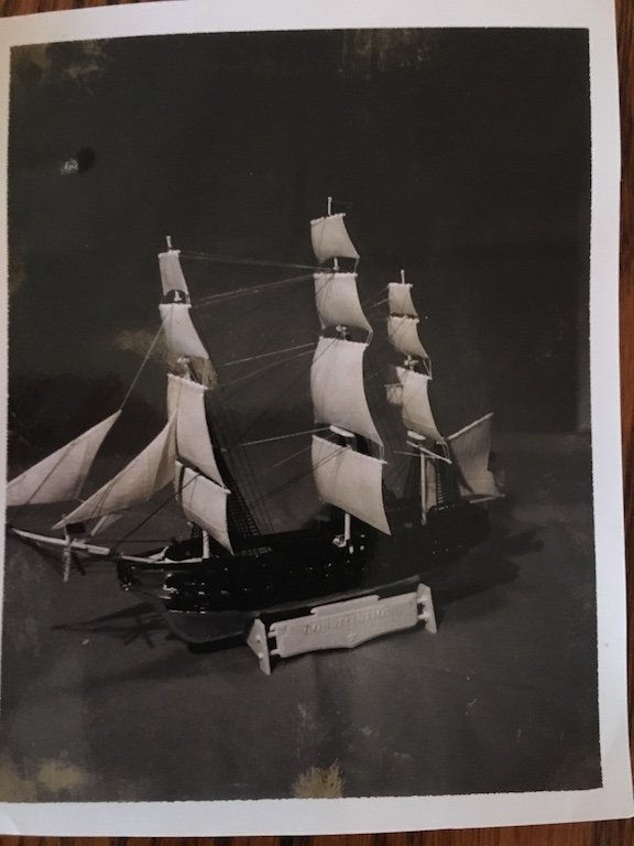
I have completed the topsail yard rigging and have started on the topgallant yards. Dan, I have to really thank you for the tip of putting the lines through the belaying pin holes first. I was not able to do this with the thicker lines on the lower yards, as the holes were too small and I didn't want to chance splitting the pin rails, but it works great on the thinner lines for the upper yards. Plus there is less room to get my hands and tools in to maneuver the lines around the belaying pin rails now, so having them secured by the pins first makes it much easier to wrap the line around the pins. I got a kick out this - we were cleaning out the attic on Saturday in preparation for our move this summer and I was looking through some old photos I took in 1968 (I was 13 years old). As far as I remember this is is the only ship model I ever built back then, and it just happens to the be same ship I am building now. Just a bit different scale and level of detail...
- 1,350 replies
-
- 4
-
-
- constitution
- model shipways
- (and 1 more)
-
Sherline mill and lathe questions
usedtosail replied to Landlubber Mike's topic in Modeling tools and Workshop Equipment
Mike, I have the long bed lathe with the milling column, and just added DRO to them. It is easy to change between the lathe and mill setup, and the only draw back is the limited movement of the XY axes in the mill setup. For example, to drill all the holes for the jackstays on the lower yards, I had to remove the yard from the vice and move it to another location. While it wasn't too hard to get it indexed to the previous location, it was still a pain. I am thinking of getting the mill base, where I can use the same Z column I already have. Maybe if that goes on sale like the DRO did... I find I like the longer bed lathe for the reasons already given. I have not had a use for it yet that the shorter bed couldn't have worked. I mounted it on a pice of pine shelving with rubber feet that I clamp to the work bench. It seems very solid. With the vertical milling column on it is top heavy, so being able to clamp it down is important. Good luck with whatever you decide on. -
Its great to see that a horizontal version is coming soon. I have been using your older model in a horizontal configuration for a while now and it works great that way.
-
Thank you J, Al, Popeye, Henry, and Art, and the likes. I have been moving slowly with the rigging but since it is so noticeable, I want to get it right.
- 1,350 replies
-
- 2
-
-
- constitution
- model shipways
- (and 1 more)
-
Very nice looking gun deck, K
-
Steve, I found that I was able to straighten the deadeyes out when I added the sheer poles just above them. I used a piece of wood between the lashings and then lashed the sheer poles to the shrouds.
- 108 replies
-
- 3
-
-
- mamoli
- constitution
- (and 2 more)
-
Great start. I built this model a few years ago and loved it. I am looking forward to following along.
-
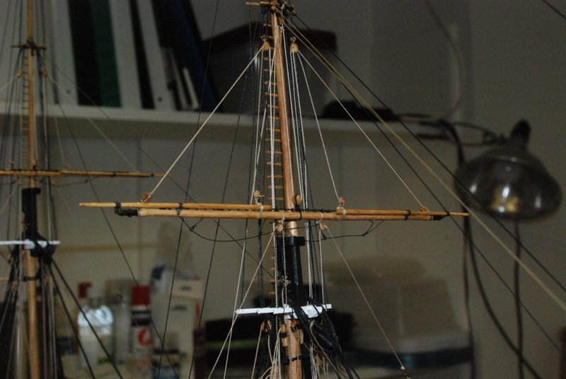
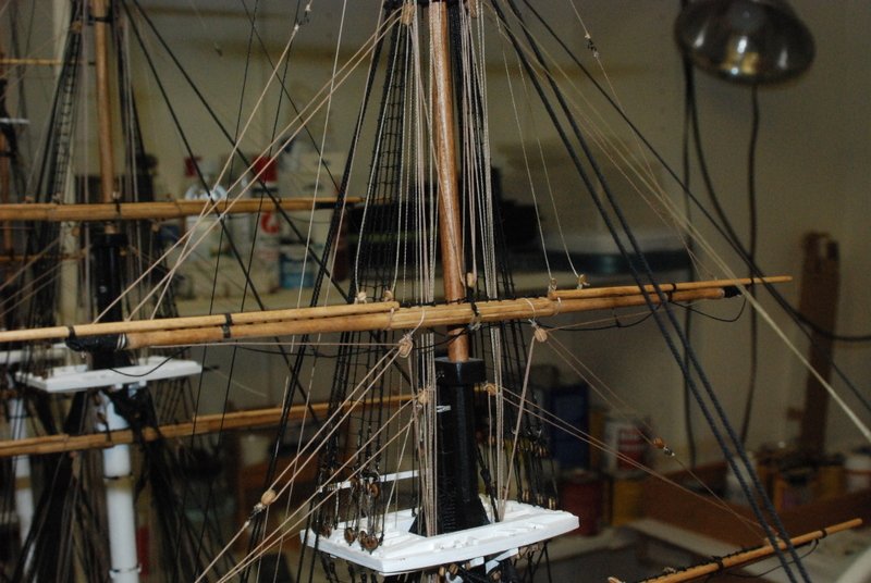
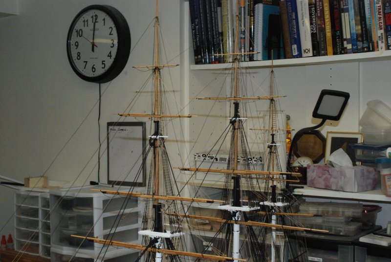
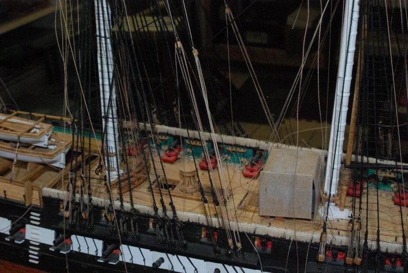
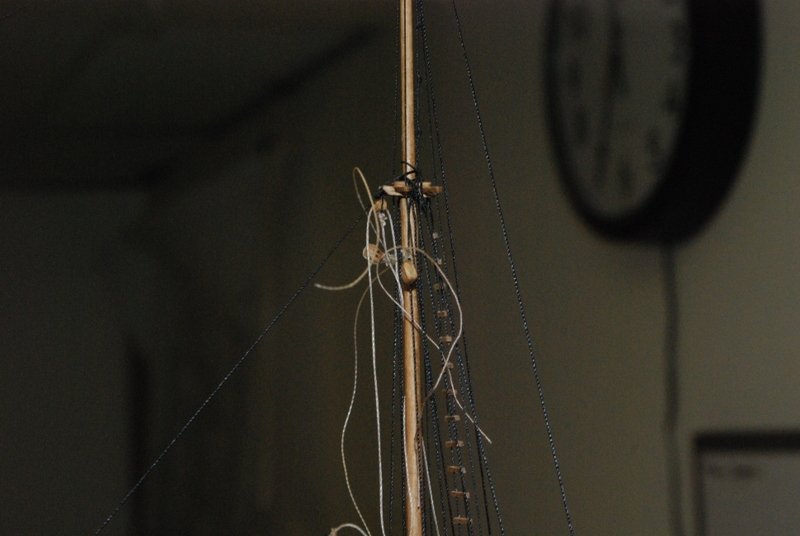
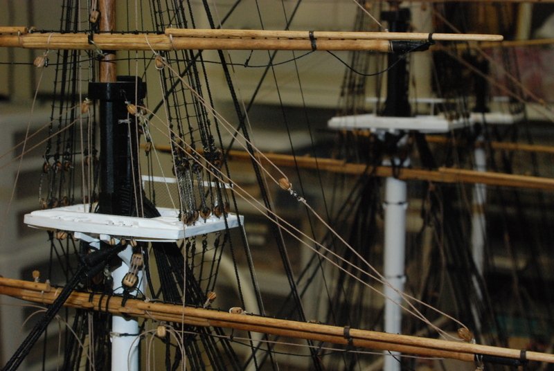
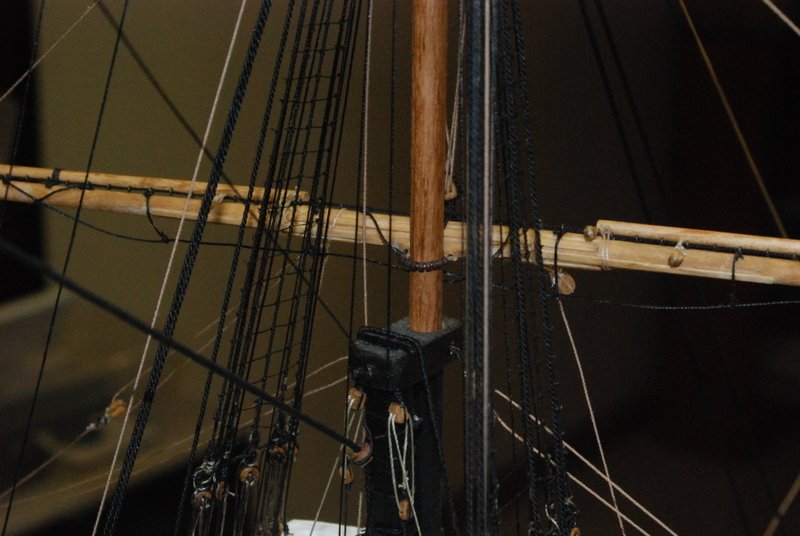
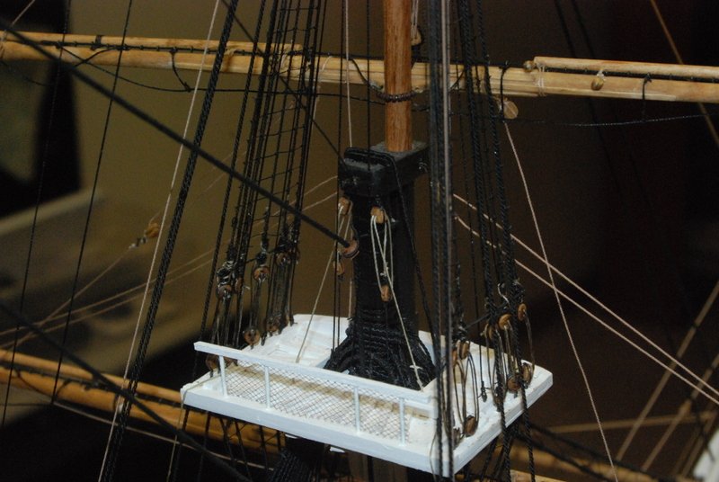
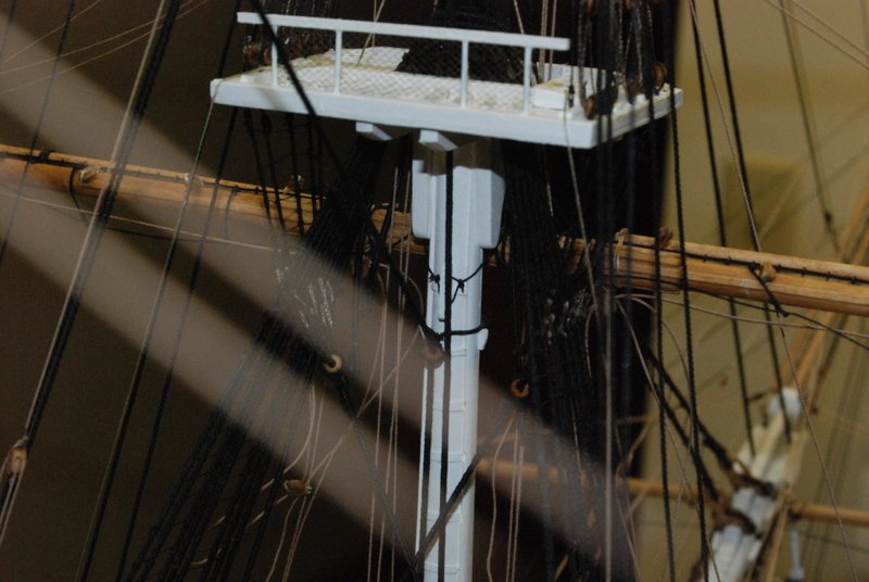
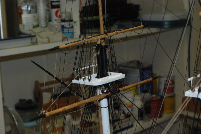
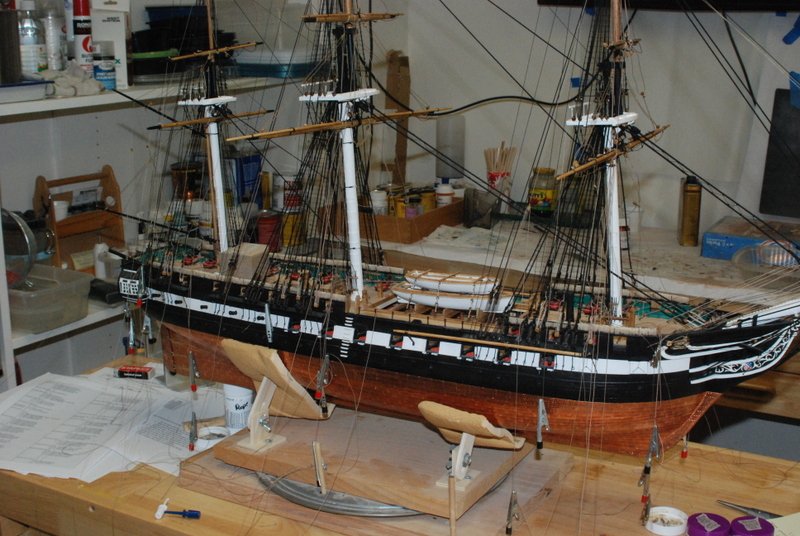
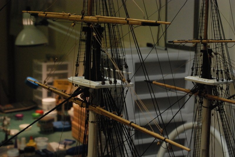
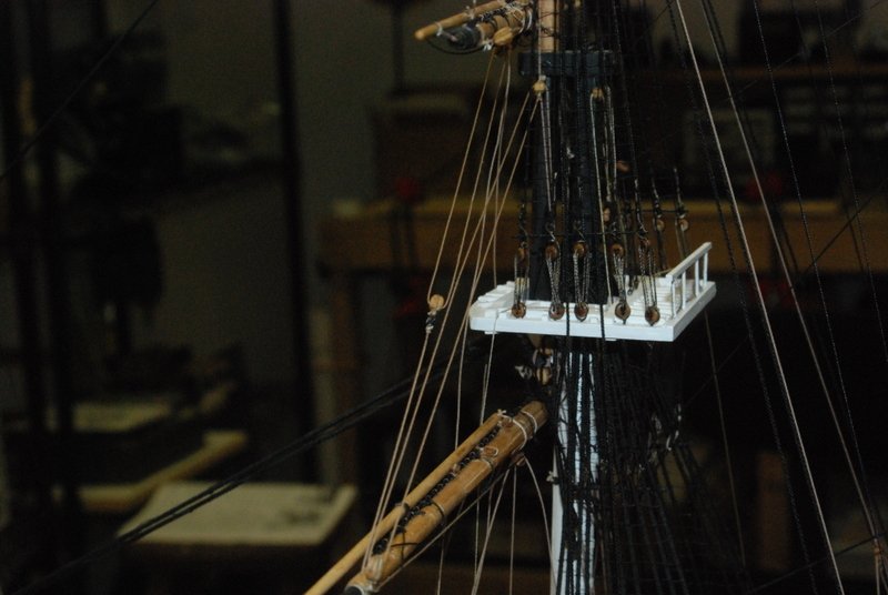
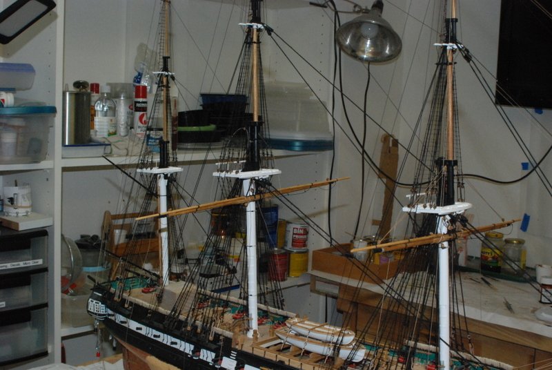
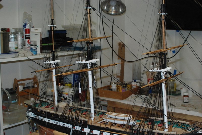
Work continues on the lower and topsail yard installation and rigging. I tried to take some more detailed shots this time to show some of the details as I have been adding them. The mizzen topsail yard was the latest to be added, with its simpler halyard arrangement than the fore and main topsail yards. I have these rigged with the tackles down to the fore and main channels. Most of the lines for these yards are now wrapped around a belaying pin or cleat, but nothing has been fixed yet so I can adjust them to all line up right. Here are some shots of the clew lines and sheets for the topsail yards. I used hooks on the sheets and hooked them into the hooks on the clew line blocks. I doubt they used hooks for the sheets on the real ship, but I wanted to have a secure connection, since I am using the sheets to put some downward pressure on the yards to counteract all of the up forces on these yards, like from the lifts. Here is a shot of one of the parrels, showing the beads that I used. These are brown seed beans, which are about 1.5mm. Here is a shot of the truss lines with their tackles on the fore top. The tackle lines are tied to cleats on the top. I found this very frustrating getting these lines secured to those cleats. I could wrap the lines around them fine, but getting the loops twisted to secure them was a bit challenging. I was able to get them all done correctly though, although I could have just wrapped and glued them in place. I like doing them the right way because I can easily undo them to adjust the tension on the lines, although getting them back around the cleats is no fun. Here is the other ends of the truss lines at the back of the fore mast. Getting these knots tied in the right place so the blocks on the other ends were in the right place was also fun, but it was doable after a few attempts. Here is the tackle line for one of the fore halyards. The blocks sit up pretty high in the air because I have these yards in the lower position, since they do not have sails. I am curious how they lowered these yards to the deck, as there does not seem to be enough line to get them all the way down without the lower block on the halyard hitting the block on the mast. I wonder if they lowered it part way with this line then tie on a different line to get to the deck? Here are the mizzen crossjack and topsail yards, still in the process of being rigged. And is an overall shot of the model so far.
- 1,350 replies
-
- 14
-
-
- constitution
- model shipways
- (and 1 more)
-
Thanks Dan. I have seen that method described before but never tried it. I'll have to give it a try. I would like to come to the joint meeting but have other plans that weekend that I can't get out of. Maybe next year.
- 1,350 replies
-
- 2
-
-
- constitution
- model shipways
- (and 1 more)
-
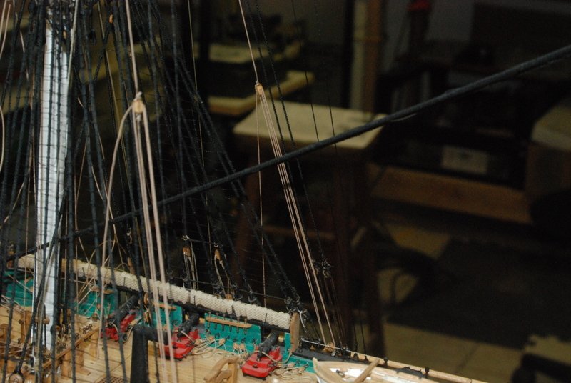
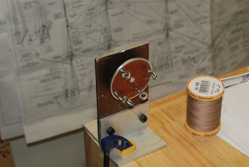
Thanks all. In between shoveling out of Nor'Easters, I have managed to get a fair amount of work on the Connie done. First though, fairly soon after my last post, I was using the wooden end of the rope walk to make 4 strand rope and it just came apart violently. So, I modified the aluminum end with more eyebolts so now I can use it for either 3 or 4 strand rope. Here it is in action making some 4 strand .020 inch diameter rope, using the thread shown above. I have the fore and main lower yards installed, with the lifts and clew lines threaded. I am holding off on the sheets and tacks until later. This picture shows them earlier without some of those lines. I have been having all kinds of problems with the mizzen lower yard, mostly with seizings coming undone as I thread various blocks. I have had to replace these in place which is a little difficult but so far not too bad. It just takes time waiting for the glue to dry on the new seizings. I currently have the triple blocks threaded and the port truss line done, and still have to redo the starboard side truss line when the block on the mast cap is dry. I have the lift lines on the yard too. I also have the fore and main topsail yards installed, with the halyard lines threaded through the block on the yard. These yards are tied onto the topmast using line between eyebolts on the parrel saddles. When I made the saddles I drilled the holes for the eyebolts but I didn't glue them in, so I now have added them to all the topsail, topGallant, and royal yards. The plans or instructions say nothing about parrels on these lines, but I used some small beads I had for them and will use them for all these yards. Last night I seized the double blocks to the ends of the halyard lines with tackle lines that will go down to another double block on the channels. I had not added the eyebolts for these blocks or the other halyard blocks to the channels so I had to drill the holes behind the backstays, which was a bit of a pain. All the eye bolts are there now. I have also added the lifts for these yards but have not threaded them through the sister blocks yet. I made the sister blocks some time ago and now I need to tie them to a shroud. This looks like it could be a little difficult too. Here are some shots from last night with the latest progress. Most lines are not permanently attached yet, so you can se that there is still some adjustment to the yards on so far to get them to line up. I really admire you guys that rigged the masts and yards together off the model. I would have no clue how to keep all those lines from becoming a big tangled mess. Even adding them one a time is getting a bit sporting. I have found that seizing lines onto the model hasn't been a big problem for me. Maybe I should say not yet anyway. Getting the lines onto belaying pins is the biggest problem so far. It takes a steady hand and lots of tries, with a fair amount of cursing in between, to get them on with a loop that holds the line in place. I haven't added any new rope coils yet either, and in fact the few coils I had on I took off because they were in the way. I will add them all later as I fill up each pin rack.
- 1,350 replies
-
- 7
-
-
- constitution
- model shipways
- (and 1 more)
-
From the Merrian Webster dictionary for point: one of the 32 equidistant spots of a compass card for indicating direction